US7780420B1 - Turbine blade with a foam metal leading or trailing edge - Google Patents
Turbine blade with a foam metal leading or trailing edge Download PDFInfo
- Publication number
- US7780420B1 US7780420B1 US11/600,455 US60045506A US7780420B1 US 7780420 B1 US7780420 B1 US 7780420B1 US 60045506 A US60045506 A US 60045506A US 7780420 B1 US7780420 B1 US 7780420B1
- Authority
- US
- United States
- Prior art keywords
- blade
- foam metal
- edge
- leading edge
- trailing edge
- Prior art date
- Legal status (The legal status is an assumption and is not a legal conclusion. Google has not performed a legal analysis and makes no representation as to the accuracy of the status listed.)
- Expired - Fee Related, expires
Links
Images


Classifications
-
- F—MECHANICAL ENGINEERING; LIGHTING; HEATING; WEAPONS; BLASTING
- F01—MACHINES OR ENGINES IN GENERAL; ENGINE PLANTS IN GENERAL; STEAM ENGINES
- F01D—NON-POSITIVE DISPLACEMENT MACHINES OR ENGINES, e.g. STEAM TURBINES
- F01D5/00—Blades; Blade-carrying members; Heating, heat-insulating, cooling or antivibration means on the blades or the members
- F01D5/12—Blades
- F01D5/14—Form or construction
-
- F—MECHANICAL ENGINEERING; LIGHTING; HEATING; WEAPONS; BLASTING
- F01—MACHINES OR ENGINES IN GENERAL; ENGINE PLANTS IN GENERAL; STEAM ENGINES
- F01D—NON-POSITIVE DISPLACEMENT MACHINES OR ENGINES, e.g. STEAM TURBINES
- F01D5/00—Blades; Blade-carrying members; Heating, heat-insulating, cooling or antivibration means on the blades or the members
- F01D5/12—Blades
- F01D5/28—Selecting particular materials; Particular measures relating thereto; Measures against erosion or corrosion
- F01D5/282—Selecting composite materials, e.g. blades with reinforcing filaments
-
- F—MECHANICAL ENGINEERING; LIGHTING; HEATING; WEAPONS; BLASTING
- F04—POSITIVE - DISPLACEMENT MACHINES FOR LIQUIDS; PUMPS FOR LIQUIDS OR ELASTIC FLUIDS
- F04D—NON-POSITIVE-DISPLACEMENT PUMPS
- F04D29/00—Details, component parts, or accessories
- F04D29/26—Rotors specially for elastic fluids
- F04D29/32—Rotors specially for elastic fluids for axial flow pumps
- F04D29/321—Rotors specially for elastic fluids for axial flow pumps for axial flow compressors
- F04D29/324—Blades
-
- F—MECHANICAL ENGINEERING; LIGHTING; HEATING; WEAPONS; BLASTING
- F05—INDEXING SCHEMES RELATING TO ENGINES OR PUMPS IN VARIOUS SUBCLASSES OF CLASSES F01-F04
- F05D—INDEXING SCHEME FOR ASPECTS RELATING TO NON-POSITIVE-DISPLACEMENT MACHINES OR ENGINES, GAS-TURBINES OR JET-PROPULSION PLANTS
- F05D2240/00—Components
- F05D2240/10—Stators
- F05D2240/12—Fluid guiding means, e.g. vanes
- F05D2240/121—Fluid guiding means, e.g. vanes related to the leading edge of a stator vane
-
- F—MECHANICAL ENGINEERING; LIGHTING; HEATING; WEAPONS; BLASTING
- F05—INDEXING SCHEMES RELATING TO ENGINES OR PUMPS IN VARIOUS SUBCLASSES OF CLASSES F01-F04
- F05D—INDEXING SCHEME FOR ASPECTS RELATING TO NON-POSITIVE-DISPLACEMENT MACHINES OR ENGINES, GAS-TURBINES OR JET-PROPULSION PLANTS
- F05D2240/00—Components
- F05D2240/10—Stators
- F05D2240/12—Fluid guiding means, e.g. vanes
- F05D2240/122—Fluid guiding means, e.g. vanes related to the trailing edge of a stator vane
-
- F—MECHANICAL ENGINEERING; LIGHTING; HEATING; WEAPONS; BLASTING
- F05—INDEXING SCHEMES RELATING TO ENGINES OR PUMPS IN VARIOUS SUBCLASSES OF CLASSES F01-F04
- F05D—INDEXING SCHEME FOR ASPECTS RELATING TO NON-POSITIVE-DISPLACEMENT MACHINES OR ENGINES, GAS-TURBINES OR JET-PROPULSION PLANTS
- F05D2240/00—Components
- F05D2240/20—Rotors
- F05D2240/30—Characteristics of rotor blades, i.e. of any element transforming dynamic fluid energy to or from rotational energy and being attached to a rotor
- F05D2240/303—Characteristics of rotor blades, i.e. of any element transforming dynamic fluid energy to or from rotational energy and being attached to a rotor related to the leading edge of a rotor blade
-
- F—MECHANICAL ENGINEERING; LIGHTING; HEATING; WEAPONS; BLASTING
- F05—INDEXING SCHEMES RELATING TO ENGINES OR PUMPS IN VARIOUS SUBCLASSES OF CLASSES F01-F04
- F05D—INDEXING SCHEME FOR ASPECTS RELATING TO NON-POSITIVE-DISPLACEMENT MACHINES OR ENGINES, GAS-TURBINES OR JET-PROPULSION PLANTS
- F05D2240/00—Components
- F05D2240/20—Rotors
- F05D2240/30—Characteristics of rotor blades, i.e. of any element transforming dynamic fluid energy to or from rotational energy and being attached to a rotor
- F05D2240/304—Characteristics of rotor blades, i.e. of any element transforming dynamic fluid energy to or from rotational energy and being attached to a rotor related to the trailing edge of a rotor blade
-
- F—MECHANICAL ENGINEERING; LIGHTING; HEATING; WEAPONS; BLASTING
- F05—INDEXING SCHEMES RELATING TO ENGINES OR PUMPS IN VARIOUS SUBCLASSES OF CLASSES F01-F04
- F05D—INDEXING SCHEME FOR ASPECTS RELATING TO NON-POSITIVE-DISPLACEMENT MACHINES OR ENGINES, GAS-TURBINES OR JET-PROPULSION PLANTS
- F05D2300/00—Materials; Properties thereof
- F05D2300/60—Properties or characteristics given to material by treatment or manufacturing
- F05D2300/603—Composites; e.g. fibre-reinforced
-
- F—MECHANICAL ENGINEERING; LIGHTING; HEATING; WEAPONS; BLASTING
- F05—INDEXING SCHEMES RELATING TO ENGINES OR PUMPS IN VARIOUS SUBCLASSES OF CLASSES F01-F04
- F05D—INDEXING SCHEME FOR ASPECTS RELATING TO NON-POSITIVE-DISPLACEMENT MACHINES OR ENGINES, GAS-TURBINES OR JET-PROPULSION PLANTS
- F05D2300/00—Materials; Properties thereof
- F05D2300/60—Properties or characteristics given to material by treatment or manufacturing
- F05D2300/612—Foam
-
- Y—GENERAL TAGGING OF NEW TECHNOLOGICAL DEVELOPMENTS; GENERAL TAGGING OF CROSS-SECTIONAL TECHNOLOGIES SPANNING OVER SEVERAL SECTIONS OF THE IPC; TECHNICAL SUBJECTS COVERED BY FORMER USPC CROSS-REFERENCE ART COLLECTIONS [XRACs] AND DIGESTS
- Y02—TECHNOLOGIES OR APPLICATIONS FOR MITIGATION OR ADAPTATION AGAINST CLIMATE CHANGE
- Y02T—CLIMATE CHANGE MITIGATION TECHNOLOGIES RELATED TO TRANSPORTATION
- Y02T50/00—Aeronautics or air transport
- Y02T50/60—Efficient propulsion technologies, e.g. for aircraft
Definitions
- the present invention relates generally to fluid reaction surfaces, and more specifically to a thin rotor blade.
- a turbomachine such as a compressor in an aircraft gas turbine engine, includes an airfoil portion with leading edge and trailing edge portions extending from the airfoil portion.
- Rotor blades have been made from a single material in the early prior art.
- the rotor blades In order to improve on the performance of the turbomachine, the rotor blades have been made from composite materials in order to lighten the blade as well as increase the blade's strength.
- the leading edge or trailing edge of the blade is made of a separate material in order to reduce damage from a foreign object striking the edge during rotor blade operation.
- a blade without a sharply defined leading or trailing edge leads to a significant loss in performance.
- U.S. Pat. No. 3,758,234 issued to Goodwin on Sep. 11, 1973 and entitled FIBER BLADE WITH LEADING EDGE REINFORCEMENT discloses a rotor blade in a gas turbine engine in which two strips of metal are joined together at the leading edge over laminations of carbon fiber reinforced resin that form the made body of the blade. The leading edge of the blade is rounded and therefore does not provide the sharp edge as in the present invention.
- a rotor blade made from a fiber reinforced composite material such as carbon fiber embedded within a polyester resin sand particles will severely damage the leading edge portion of the blade.
- This type of blade is made of strong and lightweight material, but cannot withstand the damage from the sand particles.
- a composite rotor blade having a main airfoil portion made from a strong and lightweight material such as carbon reinforced laminated material, and leading edge or trailing edge portions made from a porous foam metal material with a resin embedded within the foam metal.
- the foam metal leading or trailing edges are formed with a sharp edge in order to provide high performance for a small rotor blade.
- the fibrous material used in the main airfoil portion is positioned to extend into the leading or trailing edge portion and provide a means for the resin to secure the edge to the airfoil body when a resin is imbedded into the foam metal.
- the foam metal reinforced leading or trailing edge of the blade provides for a strong edge that will withstand foreign object strikes such that the performance of the blade will not be degraded.
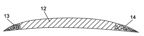
- FIG. 1 shows a top view of a cross section of a rotor blade of the present invention.
- FIG. 2 shows a front view of a cross section of the rotor blade of the present invention.
- FIG. 3 shows a cross section view of the leading edge portion of the blade.
- FIG. 4 shows a cross section of the leading edge portion of a second embodiment of the present invention.
- the present invention is a rotor blade used in a turbomachine such as a compressor in an aircraft gas turbine engine.
- a rotor blade as shown in FIG. 1 includes a main airfoil portion 12 made of a high strength and light weight materials such as carbon fiber reinforced resin.
- the leading edge 13 and trailing edge 14 portions are made of a foam metal reinforced resin composite material.
- the foam metal takes the shape of the leading or trailing edge of the blade such that a sharp edge is formed.
- the fibers used in the laminates are made to extend into the edge portion of the blade.
- FIG. 3 shows the fibers 16 from the laminated main body 12 of the blade to extend into the leading edge region 13 .
- the foam metal fibers 15 are randomly arranged to form the leading edge for the blade.
- a resinous material is injected into the foam metal fibers 15 to from a solid composite leading edge portion for the blade that includes a sharp edge and a strength capable of withstanding foreign object strikes such as by sand particles that would severely damage the composite laminated material for which the main body portion of the blade is formed from.
- both the leading edge and trailing edge portions of the blade are formed from the foam metal reinforced resin as described above.
- a blade can be formed with only a leading edge portion if desired with the trailing edge portion formed from the composite laminated material of which the main blade body portion is formed.
- FIG. 2 shows a second embodiment of the present invention in which the tip 25 of the blade 22 is also formed with the foam metal material that makes up the leading edge 23 and trailing ledge 24 portions of the blade in FIG. 1 .
- the compressor blade will be very thin.
- FIG. 4 shows a third embodiment of the present invention in which a layer of a composite laminated material such as carbon fiber reinforced with resin is applied over the pressure side and suction side of the blade.
- the suction side layer 31 and the pressure side layer 32 is applied up to a point from the leading or trailing edge that will not prevent a sharp edge formed from the foam metal from being formed.
- the layers 31 and 32 add strength to the composite blade.
Abstract
A thin compressor blade used in a small aircraft gas turbine engine, in which the blade includes a main blade portion formed from a fiber reinforced resinous composite material to provide a lightweight and strong blade, and in which the leading edge or the trailing edge of the blade is formed from a foam metal reinforced composite material that defines a sharp edge for improved performance of the thin blade. The fibers of the main body extend into the edge region in order that the resin used to bind the foam metal will also bind with the fibers of the laminates to secure the edge to the main blade body. The blade tip can also be formed from the porous foam metal and resin material to make a strong and lightweight rotor blade.
Description
1. Field of the Invention
The present invention relates generally to fluid reaction surfaces, and more specifically to a thin rotor blade.
2. Description of the Related Art Including Information Disclosed Under 37 CFR 1.97 and 1.98
A turbomachine, such as a compressor in an aircraft gas turbine engine, includes an airfoil portion with leading edge and trailing edge portions extending from the airfoil portion. Rotor blades have been made from a single material in the early prior art. In order to improve on the performance of the turbomachine, the rotor blades have been made from composite materials in order to lighten the blade as well as increase the blade's strength. In some situations, the leading edge or trailing edge of the blade is made of a separate material in order to reduce damage from a foreign object striking the edge during rotor blade operation. In a small compressor, a blade without a sharply defined leading or trailing edge leads to a significant loss in performance.
In a rotor blade used in a compressor, the leading edge and trailing edge need to be thin or sharp in order to produce a high performance in the compressor. A prior art rotor blade made from a composite material such as a composite laminated material requires a relatively large radius to wrap the laminated material around the edges of the blade. U.S. Pat. No. 3,762,835 issued to Carlson et al on Oct. 2, 1973 and entitled FOREIGN OBJECT DAMAGE PROTECTION FOR COMPRESSOR BLADES AND OTHER STRUCTURES AND RELATED METHODS discloses a composite compressor blade having a leading edge portion formed from a fine wire mesh clad in nickel. Because of the laminates, the leading edge of the blade is rounded and not sharp.
U.S. Pat. No. 3,758,234 issued to Goodwin on Sep. 11, 1973 and entitled FIBER BLADE WITH LEADING EDGE REINFORCEMENT discloses a rotor blade in a gas turbine engine in which two strips of metal are joined together at the leading edge over laminations of carbon fiber reinforced resin that form the made body of the blade. The leading edge of the blade is rounded and therefore does not provide the sharp edge as in the present invention.
In a rotor blade made from a fiber reinforced composite material such as carbon fiber embedded within a polyester resin, sand particles will severely damage the leading edge portion of the blade. This type of blade is made of strong and lightweight material, but cannot withstand the damage from the sand particles.
It is therefore an object of the present invention to provide for a small rotor blade that will have a sharp leading or trailing edge in order to provide higher performance over the cited prior art references, and to have the lightweight and strength required to withstand damage from sand particles or other foreign objects that would damage the leading or trailing edge.
A composite rotor blade having a main airfoil portion made from a strong and lightweight material such as carbon reinforced laminated material, and leading edge or trailing edge portions made from a porous foam metal material with a resin embedded within the foam metal. The foam metal leading or trailing edges are formed with a sharp edge in order to provide high performance for a small rotor blade. The fibrous material used in the main airfoil portion is positioned to extend into the leading or trailing edge portion and provide a means for the resin to secure the edge to the airfoil body when a resin is imbedded into the foam metal. The foam metal reinforced leading or trailing edge of the blade provides for a strong edge that will withstand foreign object strikes such that the performance of the blade will not be degraded.
The present invention is a rotor blade used in a turbomachine such as a compressor in an aircraft gas turbine engine. A rotor blade as shown in FIG. 1 includes a main airfoil portion 12 made of a high strength and light weight materials such as carbon fiber reinforced resin. The leading edge 13 and trailing edge 14 portions are made of a foam metal reinforced resin composite material. The foam metal takes the shape of the leading or trailing edge of the blade such that a sharp edge is formed. In order to secure the foam metal edge to the airfoil main body 12, the fibers used in the laminates are made to extend into the edge portion of the blade. FIG. 3 shows the fibers 16 from the laminated main body 12 of the blade to extend into the leading edge region 13. the foam metal fibers 15 are randomly arranged to form the leading edge for the blade. A resinous material is injected into the foam metal fibers 15 to from a solid composite leading edge portion for the blade that includes a sharp edge and a strength capable of withstanding foreign object strikes such as by sand particles that would severely damage the composite laminated material for which the main body portion of the blade is formed from.
In the present invention of FIG. 1 , both the leading edge and trailing edge portions of the blade are formed from the foam metal reinforced resin as described above. However, a blade can be formed with only a leading edge portion if desired with the trailing edge portion formed from the composite laminated material of which the main blade body portion is formed.
Claims (4)
1. A thin rotor blade for use in a turbomachine, the blade comprising:
a main body portion formed from a composite laminated material;
a leading edge region formed from a foam metal embedded with a resinous material, the leading edge having a sharp edge; and,
the fibers of the composite laminated material extending into the leading edge region such that the resin of the foam metal also engages with the fibers to secure the leading edge to the blade main body portion.
2. The thin rotor blade of claim 1 , and further comprising:
the blade tip is formed from a foam metal reinforced resin composite material.
3. The thin rotor blade of claim 1 , and further comprising:
a trailing edge formed from a foam metal embedded with a resinous material with a sharp edge.
4. A thin rotor blade for use in a turbomachine, the blade comprising:
a main body portion formed from a composite laminated material; and,
a leading edge region formed from a foam metal embedded with a resinous material, the leading edge having a sharp edge;
the blade tip is formed from a foam metal reinforced resin composite material; and,
the leading edge and the blade tip are a single piece foam metal.
Priority Applications (1)
| Application Number | Priority Date | Filing Date | Title |
|---|---|---|---|
| US11/600,455 US7780420B1 (en) | 2006-11-16 | 2006-11-16 | Turbine blade with a foam metal leading or trailing edge |
Applications Claiming Priority (1)
| Application Number | Priority Date | Filing Date | Title |
|---|---|---|---|
| US11/600,455 US7780420B1 (en) | 2006-11-16 | 2006-11-16 | Turbine blade with a foam metal leading or trailing edge |
Publications (1)
| Publication Number | Publication Date |
|---|---|
| US7780420B1 true US7780420B1 (en) | 2010-08-24 |
Family
ID=42583274
Family Applications (1)
| Application Number | Title | Priority Date | Filing Date |
|---|---|---|---|
| US11/600,455 Expired - Fee Related US7780420B1 (en) | 2006-11-16 | 2006-11-16 | Turbine blade with a foam metal leading or trailing edge |
Country Status (1)
| Country | Link |
|---|---|
| US (1) | US7780420B1 (en) |
Cited By (28)
| Publication number | Priority date | Publication date | Assignee | Title |
|---|---|---|---|---|
| US20120163982A1 (en) * | 2010-12-27 | 2012-06-28 | Edward Claude Rice | Airfoil, turbomachine and gas turbine engine |
| US20150218964A1 (en) * | 2014-02-05 | 2015-08-06 | Rolls-Royce Plc | Fan casing for a gas turbine engine |
| WO2015175168A1 (en) | 2014-05-12 | 2015-11-19 | Siemens Energy, Inc. | Laser deposition of metal foam |
| US9222362B2 (en) | 2010-11-05 | 2015-12-29 | Barnes Group Inc. | Hybrid metal leading edge part and method for making the same |
| US20160084093A1 (en) * | 2011-06-21 | 2016-03-24 | General Electric Technology Gmbh | Turbine Airfoil of Composite Material and Method of Manufacturing Thereof |
| FR3027959A1 (en) * | 2014-10-31 | 2016-05-06 | Safran | FIRE PROTECTION OF A COMPOSITE MATERIAL PART OF A GAS TURBINE |
| US20160230569A1 (en) * | 2013-09-23 | 2016-08-11 | United Technologies Corporation | Cmc airfoil with sharp trailing edge and method of making same |
| EP2703605A3 (en) * | 2012-08-29 | 2017-06-14 | Rolls-Royce plc | A gas turbine blade tip omprising a metallic foam material |
| FR3049001A1 (en) * | 2016-03-21 | 2017-09-22 | Snecma | A CARRIED PROPELLER AERONAUTICAL TURBOMACHINE HAVING BLADES HAVING AN ELEMENT REPORTED IN COMPOSITE MATERIAL GLUE ON THEIR EDGE EDGE |
| FR3049002A1 (en) * | 2016-03-21 | 2017-09-22 | Snecma | AERONAUTICAL TURBOMACHINE BLADE COMPRISING AN ELEMENT REPORTED IN COMPOSITE MATERIAL FORMING A LEAK EDGE AND METHOD OF MANUFACTURING SUCH A BLADE |
| US9777593B2 (en) | 2015-02-23 | 2017-10-03 | General Electric Company | Hybrid metal and composite spool for rotating machinery |
| US20170298740A1 (en) * | 2014-06-16 | 2017-10-19 | Brunel University | Noise Reduction to the Trailing Edge of Fluid Dynamic Bodies |
| WO2017186640A1 (en) * | 2016-04-25 | 2017-11-02 | Siemens Aktiengesellschaft | Hybrid rotor blade or guide blade and method for the production thereof |
| US9850764B2 (en) | 2014-02-28 | 2017-12-26 | Rolls-Royce Plc | Blade tip |
| US10047763B2 (en) | 2015-12-14 | 2018-08-14 | General Electric Company | Rotor assembly for use in a turbofan engine and method of assembling |
| CN109877318A (en) * | 2017-12-06 | 2019-06-14 | 安萨尔多能源英国知识产权有限公司 | Composite component and method for manufacturing it |
| US10337405B2 (en) | 2016-05-17 | 2019-07-02 | General Electric Company | Method and system for bowed rotor start mitigation using rotor cooling |
| US10583933B2 (en) | 2016-10-03 | 2020-03-10 | General Electric Company | Method and apparatus for undercowl flow diversion cooling |
| US10920607B2 (en) | 2018-09-28 | 2021-02-16 | General Electric Company | Metallic compliant tip fan blade |
| US10947993B2 (en) | 2017-11-27 | 2021-03-16 | General Electric Company | Thermal gradient attenuation structure to mitigate rotor bow in turbine engine |
| CN112607003A (en) * | 2020-11-25 | 2021-04-06 | 常州市长昊机械有限公司 | Easily accomodate formula aviation blade |
| US11053861B2 (en) | 2016-03-03 | 2021-07-06 | General Electric Company | Overspeed protection system and method |
| US11149642B2 (en) | 2015-12-30 | 2021-10-19 | General Electric Company | System and method of reducing post-shutdown engine temperatures |
| US11286807B2 (en) | 2018-09-28 | 2022-03-29 | General Electric Company | Metallic compliant tip fan blade |
| US20220136394A1 (en) * | 2020-10-30 | 2022-05-05 | Raytheon Technologies Corporation | Composite fan blade leading edge sheath with encapsulating extension |
| US11713686B2 (en) * | 2017-05-16 | 2023-08-01 | Oscar Propulsion Ltd. | Outlet guide vanes |
| US11753942B1 (en) * | 2022-04-11 | 2023-09-12 | General Electric Company | Frangible airfoils |
| US11879411B2 (en) | 2022-04-07 | 2024-01-23 | General Electric Company | System and method for mitigating bowed rotor in a gas turbine engine |
Citations (20)
| Publication number | Priority date | Publication date | Assignee | Title |
|---|---|---|---|---|
| US2917384A (en) * | 1956-01-19 | 1959-12-15 | Gen Electric | Method of making foam material from nickel powder |
| US3294366A (en) | 1965-04-20 | 1966-12-27 | Rolls Royce | Blades for gas turbine engines |
| US3758234A (en) | 1968-10-22 | 1973-09-11 | Secr Defence | Fiber blade with leading edge reinforcement |
| US3762835A (en) | 1971-07-02 | 1973-10-02 | Gen Electric | Foreign object damage protection for compressor blades and other structures and related methods |
| US3778188A (en) | 1972-09-11 | 1973-12-11 | Gen Motors Corp | Cooled turbine rotor and its manufacture |
| US3844728A (en) | 1968-03-20 | 1974-10-29 | United Aircraft Corp | Gas contacting element leading edge and trailing edge insert |
| US3892612A (en) | 1971-07-02 | 1975-07-01 | Gen Electric | Method for fabricating foreign object damage protection for rotar blades |
| US4006999A (en) | 1975-07-17 | 1977-02-08 | The United States Of America As Represented By The Administrator Of The National Aeronautics And Space Administration | Leading edge protection for composite blades |
| US4111606A (en) | 1976-12-27 | 1978-09-05 | United Technologies Corporation | Composite rotor blade |
| US4247259A (en) | 1979-04-18 | 1981-01-27 | Avco Corporation | Composite ceramic/metallic turbine blade and method of making same |
| US5174024A (en) | 1990-09-17 | 1992-12-29 | Sterrett Terry L | Tail rotor abrasive strip |
| US5348446A (en) | 1993-04-28 | 1994-09-20 | General Electric Company | Bimetallic turbine airfoil |
| US5449273A (en) | 1994-03-21 | 1995-09-12 | United Technologies Corporation | Composite airfoil leading edge protection |
| US5876651A (en) | 1996-05-29 | 1999-03-02 | United Technologies Corporation | Method for forming a composite structure |
| US5887332A (en) | 1996-02-29 | 1999-03-30 | Societe Nationale D'etude Et De Construction De Moteurs D'aviation "Snecma" | Hybrid component with high strength/mass ratio and method of manufacturing said component |
| US6682022B2 (en) | 1999-11-24 | 2004-01-27 | Lorenzo Battisti | Boundary layer control of aerodynamic airfoils |
| WO2005056220A1 (en) * | 2003-12-10 | 2005-06-23 | Mtu Aero Engines Gmbh | Method for producing gas turbine components and component for a gas turbine |
| US6960065B2 (en) | 2001-03-14 | 2005-11-01 | Leach Aero Services Pty. Ltd. | Aerodynamic article with protective coating and method of bonding metal to polyurethane |
| US20060216154A1 (en) * | 2004-12-22 | 2006-09-28 | Rolls-Royce Plc | Composite blade |
| US7156622B2 (en) * | 2003-02-22 | 2007-01-02 | Rolls-Royce Deutschland Ltd & Co Kg | Compressor blade for an aircraft engine |
-
2006
- 2006-11-16 US US11/600,455 patent/US7780420B1/en not_active Expired - Fee Related
Patent Citations (23)
| Publication number | Priority date | Publication date | Assignee | Title |
|---|---|---|---|---|
| US2917384A (en) * | 1956-01-19 | 1959-12-15 | Gen Electric | Method of making foam material from nickel powder |
| US3294366A (en) | 1965-04-20 | 1966-12-27 | Rolls Royce | Blades for gas turbine engines |
| US3844728A (en) | 1968-03-20 | 1974-10-29 | United Aircraft Corp | Gas contacting element leading edge and trailing edge insert |
| US3758234A (en) | 1968-10-22 | 1973-09-11 | Secr Defence | Fiber blade with leading edge reinforcement |
| US3762835A (en) | 1971-07-02 | 1973-10-02 | Gen Electric | Foreign object damage protection for compressor blades and other structures and related methods |
| US3892612A (en) | 1971-07-02 | 1975-07-01 | Gen Electric | Method for fabricating foreign object damage protection for rotar blades |
| US3778188A (en) | 1972-09-11 | 1973-12-11 | Gen Motors Corp | Cooled turbine rotor and its manufacture |
| US4006999A (en) | 1975-07-17 | 1977-02-08 | The United States Of America As Represented By The Administrator Of The National Aeronautics And Space Administration | Leading edge protection for composite blades |
| US4111606A (en) | 1976-12-27 | 1978-09-05 | United Technologies Corporation | Composite rotor blade |
| US4247259A (en) | 1979-04-18 | 1981-01-27 | Avco Corporation | Composite ceramic/metallic turbine blade and method of making same |
| US5174024A (en) | 1990-09-17 | 1992-12-29 | Sterrett Terry L | Tail rotor abrasive strip |
| US5348446A (en) | 1993-04-28 | 1994-09-20 | General Electric Company | Bimetallic turbine airfoil |
| US5449273A (en) | 1994-03-21 | 1995-09-12 | United Technologies Corporation | Composite airfoil leading edge protection |
| US5887332A (en) | 1996-02-29 | 1999-03-30 | Societe Nationale D'etude Et De Construction De Moteurs D'aviation "Snecma" | Hybrid component with high strength/mass ratio and method of manufacturing said component |
| US6132857A (en) | 1996-02-29 | 2000-10-17 | Societe Nationale D'etude Et De Construction De Moterus D'aviation "Snecma" | Hybrid component with high strength/mass ratio and method of manufacturing said component |
| US5876651A (en) | 1996-05-29 | 1999-03-02 | United Technologies Corporation | Method for forming a composite structure |
| US5965240A (en) | 1996-05-29 | 1999-10-12 | United Technologies Corporation | Metal/composite |
| US6682022B2 (en) | 1999-11-24 | 2004-01-27 | Lorenzo Battisti | Boundary layer control of aerodynamic airfoils |
| US6960065B2 (en) | 2001-03-14 | 2005-11-01 | Leach Aero Services Pty. Ltd. | Aerodynamic article with protective coating and method of bonding metal to polyurethane |
| US7156622B2 (en) * | 2003-02-22 | 2007-01-02 | Rolls-Royce Deutschland Ltd & Co Kg | Compressor blade for an aircraft engine |
| WO2005056220A1 (en) * | 2003-12-10 | 2005-06-23 | Mtu Aero Engines Gmbh | Method for producing gas turbine components and component for a gas turbine |
| US20070122606A1 (en) * | 2003-12-10 | 2007-05-31 | Mtu Aero Engines Gmbh | Method for producing gas turbine components and component for a gas turbine |
| US20060216154A1 (en) * | 2004-12-22 | 2006-09-28 | Rolls-Royce Plc | Composite blade |
Cited By (37)
| Publication number | Priority date | Publication date | Assignee | Title |
|---|---|---|---|---|
| US9222362B2 (en) | 2010-11-05 | 2015-12-29 | Barnes Group Inc. | Hybrid metal leading edge part and method for making the same |
| US20120163982A1 (en) * | 2010-12-27 | 2012-06-28 | Edward Claude Rice | Airfoil, turbomachine and gas turbine engine |
| US9004873B2 (en) * | 2010-12-27 | 2015-04-14 | Rolls-Royce Corporation | Airfoil, turbomachine and gas turbine engine |
| US20160084093A1 (en) * | 2011-06-21 | 2016-03-24 | General Electric Technology Gmbh | Turbine Airfoil of Composite Material and Method of Manufacturing Thereof |
| US9587497B2 (en) * | 2011-06-21 | 2017-03-07 | General Electric Technology Gmbh | Turbine airfoil of composite material and method of manufacturing thereof |
| EP2703605A3 (en) * | 2012-08-29 | 2017-06-14 | Rolls-Royce plc | A gas turbine blade tip omprising a metallic foam material |
| US20160230569A1 (en) * | 2013-09-23 | 2016-08-11 | United Technologies Corporation | Cmc airfoil with sharp trailing edge and method of making same |
| US20150218964A1 (en) * | 2014-02-05 | 2015-08-06 | Rolls-Royce Plc | Fan casing for a gas turbine engine |
| US9822663B2 (en) * | 2014-02-05 | 2017-11-21 | Rolls-Royce Plc | Fan casing for a gas turbine engine |
| US9850764B2 (en) | 2014-02-28 | 2017-12-26 | Rolls-Royce Plc | Blade tip |
| WO2015175168A1 (en) | 2014-05-12 | 2015-11-19 | Siemens Energy, Inc. | Laser deposition of metal foam |
| US10900465B2 (en) * | 2014-06-16 | 2021-01-26 | Brunel University London | Noise reduction to the trailing edge of fluid dynamic bodies |
| US20170298740A1 (en) * | 2014-06-16 | 2017-10-19 | Brunel University | Noise Reduction to the Trailing Edge of Fluid Dynamic Bodies |
| FR3027959A1 (en) * | 2014-10-31 | 2016-05-06 | Safran | FIRE PROTECTION OF A COMPOSITE MATERIAL PART OF A GAS TURBINE |
| US9777593B2 (en) | 2015-02-23 | 2017-10-03 | General Electric Company | Hybrid metal and composite spool for rotating machinery |
| US10047763B2 (en) | 2015-12-14 | 2018-08-14 | General Electric Company | Rotor assembly for use in a turbofan engine and method of assembling |
| US11384690B2 (en) | 2015-12-30 | 2022-07-12 | General Electric Company | System and method of reducing post-shutdown engine temperatures |
| US11149642B2 (en) | 2015-12-30 | 2021-10-19 | General Electric Company | System and method of reducing post-shutdown engine temperatures |
| US11053861B2 (en) | 2016-03-03 | 2021-07-06 | General Electric Company | Overspeed protection system and method |
| US11401823B2 (en) | 2016-03-21 | 2022-08-02 | Safran Aircraft Engines | Aircraft turbomachine provided with an unducted propeller with blades having a composite-material insert bonded to their leading edges |
| WO2017162964A1 (en) * | 2016-03-21 | 2017-09-28 | Safran Aircraft Engines | Aircraft turbomachine provided with an unducted propeller with blades having a composite-material insert bonded to their leading edges |
| FR3049001A1 (en) * | 2016-03-21 | 2017-09-22 | Snecma | A CARRIED PROPELLER AERONAUTICAL TURBOMACHINE HAVING BLADES HAVING AN ELEMENT REPORTED IN COMPOSITE MATERIAL GLUE ON THEIR EDGE EDGE |
| FR3049002A1 (en) * | 2016-03-21 | 2017-09-22 | Snecma | AERONAUTICAL TURBOMACHINE BLADE COMPRISING AN ELEMENT REPORTED IN COMPOSITE MATERIAL FORMING A LEAK EDGE AND METHOD OF MANUFACTURING SUCH A BLADE |
| WO2017186640A1 (en) * | 2016-04-25 | 2017-11-02 | Siemens Aktiengesellschaft | Hybrid rotor blade or guide blade and method for the production thereof |
| US10337405B2 (en) | 2016-05-17 | 2019-07-02 | General Electric Company | Method and system for bowed rotor start mitigation using rotor cooling |
| US10583933B2 (en) | 2016-10-03 | 2020-03-10 | General Electric Company | Method and apparatus for undercowl flow diversion cooling |
| US11713686B2 (en) * | 2017-05-16 | 2023-08-01 | Oscar Propulsion Ltd. | Outlet guide vanes |
| US10947993B2 (en) | 2017-11-27 | 2021-03-16 | General Electric Company | Thermal gradient attenuation structure to mitigate rotor bow in turbine engine |
| CN109877318B (en) * | 2017-12-06 | 2023-08-04 | 安萨尔多能源英国知识产权有限公司 | Composite component and method for producing same |
| CN109877318A (en) * | 2017-12-06 | 2019-06-14 | 安萨尔多能源英国知识产权有限公司 | Composite component and method for manufacturing it |
| US11286807B2 (en) | 2018-09-28 | 2022-03-29 | General Electric Company | Metallic compliant tip fan blade |
| US10920607B2 (en) | 2018-09-28 | 2021-02-16 | General Electric Company | Metallic compliant tip fan blade |
| US20220136394A1 (en) * | 2020-10-30 | 2022-05-05 | Raytheon Technologies Corporation | Composite fan blade leading edge sheath with encapsulating extension |
| CN112607003B (en) * | 2020-11-25 | 2023-06-20 | 常州市长昊机械有限公司 | Easily accomodate formula aviation blade |
| CN112607003A (en) * | 2020-11-25 | 2021-04-06 | 常州市长昊机械有限公司 | Easily accomodate formula aviation blade |
| US11879411B2 (en) | 2022-04-07 | 2024-01-23 | General Electric Company | System and method for mitigating bowed rotor in a gas turbine engine |
| US11753942B1 (en) * | 2022-04-11 | 2023-09-12 | General Electric Company | Frangible airfoils |
Similar Documents
| Publication | Publication Date | Title |
|---|---|---|
| US7780420B1 (en) | Turbine blade with a foam metal leading or trailing edge | |
| US9556742B2 (en) | Composite airfoil and turbine engine | |
| EP1887187B1 (en) | Rotor blade | |
| US20110229334A1 (en) | Composite leading edge sheath and dovetail root undercut | |
| US20110070092A1 (en) | Hybrid component | |
| US10138738B2 (en) | Composite vane | |
| JP3924333B2 (en) | Composite blade | |
| US8851855B2 (en) | Composite turbomachine blade | |
| EP2295723B1 (en) | A composite airfoil made of a three dimensional woven core and a composite skin and method of manufacturing this airfoil | |
| EP3561232B1 (en) | Composite component | |
| EP2096269B1 (en) | Fan track liner assembly for a gas turbine engine | |
| US20110194941A1 (en) | Co-cured sheath for composite blade | |
| EP2543823A2 (en) | Ceramic matrix composite components | |
| JP2013036466A (en) | Reinforced fan blade and method of making the same | |
| EP3130758B1 (en) | Composite vane | |
| JP2007270843A (en) | Aerofoil section having dovetail-shaped cavity of hybrid bucket for mechanical retention | |
| EP3517732B1 (en) | Reinforced composite blade and method of making a blade | |
| US11105210B2 (en) | Blade comprising a leading edge shield and method for producing the blade | |
| RU2718381C1 (en) | Fan blade | |
| CN111828386A (en) | Combined fan blade | |
| RU2282726C1 (en) | Turbomachine composition blade |
Legal Events
| Date | Code | Title | Description |
|---|---|---|---|
| REMI | Maintenance fee reminder mailed | ||
| FPAY | Fee payment |
Year of fee payment: 4 |
|
| SULP | Surcharge for late payment | ||
| FEPP | Fee payment procedure |
Free format text: MAINTENANCE FEE REMINDER MAILED (ORIGINAL EVENT CODE: REM.) |
|
| LAPS | Lapse for failure to pay maintenance fees |
Free format text: PATENT EXPIRED FOR FAILURE TO PAY MAINTENANCE FEES (ORIGINAL EVENT CODE: EXP.); ENTITY STATUS OF PATENT OWNER: SMALL ENTITY |
|
| STCH | Information on status: patent discontinuation |
Free format text: PATENT EXPIRED DUE TO NONPAYMENT OF MAINTENANCE FEES UNDER 37 CFR 1.362 |
|
| FP | Lapsed due to failure to pay maintenance fee |
Effective date: 20180824 |