US7780597B2 - Method and apparatus for improving the performance of capacitive acoustic transducers using bias polarity control and multiple firings - Google Patents
Method and apparatus for improving the performance of capacitive acoustic transducers using bias polarity control and multiple firings Download PDFInfo
- Publication number
- US7780597B2 US7780597B2 US10/819,094 US81909404A US7780597B2 US 7780597 B2 US7780597 B2 US 7780597B2 US 81909404 A US81909404 A US 81909404A US 7780597 B2 US7780597 B2 US 7780597B2
- Authority
- US
- United States
- Prior art keywords
- transmit
- bias voltage
- voltage polarity
- receive
- data
- Prior art date
- Legal status (The legal status is an assumption and is not a legal conclusion. Google has not performed a legal analysis and makes no representation as to the accuracy of the status listed.)
- Expired - Fee Related, expires
Links
Images


Classifications
-
- G—PHYSICS
- G01—MEASURING; TESTING
- G01S—RADIO DIRECTION-FINDING; RADIO NAVIGATION; DETERMINING DISTANCE OR VELOCITY BY USE OF RADIO WAVES; LOCATING OR PRESENCE-DETECTING BY USE OF THE REFLECTION OR RERADIATION OF RADIO WAVES; ANALOGOUS ARRANGEMENTS USING OTHER WAVES
- G01S15/00—Systems using the reflection or reradiation of acoustic waves, e.g. sonar systems
- G01S15/88—Sonar systems specially adapted for specific applications
- G01S15/89—Sonar systems specially adapted for specific applications for mapping or imaging
- G01S15/8906—Short-range imaging systems; Acoustic microscope systems using pulse-echo techniques
- G01S15/8959—Short-range imaging systems; Acoustic microscope systems using pulse-echo techniques using coded signals for correlation purposes
-
- B—PERFORMING OPERATIONS; TRANSPORTING
- B06—GENERATING OR TRANSMITTING MECHANICAL VIBRATIONS IN GENERAL
- B06B—METHODS OR APPARATUS FOR GENERATING OR TRANSMITTING MECHANICAL VIBRATIONS OF INFRASONIC, SONIC, OR ULTRASONIC FREQUENCY, e.g. FOR PERFORMING MECHANICAL WORK IN GENERAL
- B06B1/00—Methods or apparatus for generating mechanical vibrations of infrasonic, sonic, or ultrasonic frequency
- B06B1/02—Methods or apparatus for generating mechanical vibrations of infrasonic, sonic, or ultrasonic frequency making use of electrical energy
- B06B1/0292—Electrostatic transducers, e.g. electret-type
-
- G—PHYSICS
- G01—MEASURING; TESTING
- G01S—RADIO DIRECTION-FINDING; RADIO NAVIGATION; DETERMINING DISTANCE OR VELOCITY BY USE OF RADIO WAVES; LOCATING OR PRESENCE-DETECTING BY USE OF THE REFLECTION OR RERADIATION OF RADIO WAVES; ANALOGOUS ARRANGEMENTS USING OTHER WAVES
- G01S15/00—Systems using the reflection or reradiation of acoustic waves, e.g. sonar systems
- G01S15/88—Sonar systems specially adapted for specific applications
- G01S15/89—Sonar systems specially adapted for specific applications for mapping or imaging
- G01S15/8906—Short-range imaging systems; Acoustic microscope systems using pulse-echo techniques
- G01S15/8909—Short-range imaging systems; Acoustic microscope systems using pulse-echo techniques using a static transducer configuration
-
- G—PHYSICS
- G01—MEASURING; TESTING
- G01S—RADIO DIRECTION-FINDING; RADIO NAVIGATION; DETERMINING DISTANCE OR VELOCITY BY USE OF RADIO WAVES; LOCATING OR PRESENCE-DETECTING BY USE OF THE REFLECTION OR RERADIATION OF RADIO WAVES; ANALOGOUS ARRANGEMENTS USING OTHER WAVES
- G01S7/00—Details of systems according to groups G01S13/00, G01S15/00, G01S17/00
- G01S7/52—Details of systems according to groups G01S13/00, G01S15/00, G01S17/00 of systems according to group G01S15/00
- G01S7/52017—Details of systems according to groups G01S13/00, G01S15/00, G01S17/00 of systems according to group G01S15/00 particularly adapted to short-range imaging
- G01S7/52023—Details of receivers
- G01S7/52036—Details of receivers using analysis of echo signal for target characterisation
- G01S7/52038—Details of receivers using analysis of echo signal for target characterisation involving non-linear properties of the propagation medium or of the reflective target
-
- G—PHYSICS
- G01—MEASURING; TESTING
- G01S—RADIO DIRECTION-FINDING; RADIO NAVIGATION; DETERMINING DISTANCE OR VELOCITY BY USE OF RADIO WAVES; LOCATING OR PRESENCE-DETECTING BY USE OF THE REFLECTION OR RERADIATION OF RADIO WAVES; ANALOGOUS ARRANGEMENTS USING OTHER WAVES
- G01S15/00—Systems using the reflection or reradiation of acoustic waves, e.g. sonar systems
- G01S15/88—Sonar systems specially adapted for specific applications
- G01S15/89—Sonar systems specially adapted for specific applications for mapping or imaging
- G01S15/8906—Short-range imaging systems; Acoustic microscope systems using pulse-echo techniques
- G01S15/8995—Combining images from different aspect angles, e.g. spatial compounding
-
- G—PHYSICS
- G01—MEASURING; TESTING
- G01S—RADIO DIRECTION-FINDING; RADIO NAVIGATION; DETERMINING DISTANCE OR VELOCITY BY USE OF RADIO WAVES; LOCATING OR PRESENCE-DETECTING BY USE OF THE REFLECTION OR RERADIATION OF RADIO WAVES; ANALOGOUS ARRANGEMENTS USING OTHER WAVES
- G01S7/00—Details of systems according to groups G01S13/00, G01S15/00, G01S17/00
- G01S7/52—Details of systems according to groups G01S13/00, G01S15/00, G01S17/00 of systems according to group G01S15/00
- G01S7/52017—Details of systems according to groups G01S13/00, G01S15/00, G01S17/00 of systems according to group G01S15/00 particularly adapted to short-range imaging
- G01S7/52046—Techniques for image enhancement involving transmitter or receiver
- G01S7/52047—Techniques for image enhancement involving transmitter or receiver for elimination of side lobes or of grating lobes; for increasing resolving power
-
- G—PHYSICS
- G01—MEASURING; TESTING
- G01S—RADIO DIRECTION-FINDING; RADIO NAVIGATION; DETERMINING DISTANCE OR VELOCITY BY USE OF RADIO WAVES; LOCATING OR PRESENCE-DETECTING BY USE OF THE REFLECTION OR RERADIATION OF RADIO WAVES; ANALOGOUS ARRANGEMENTS USING OTHER WAVES
- G01S7/00—Details of systems according to groups G01S13/00, G01S15/00, G01S17/00
- G01S7/52—Details of systems according to groups G01S13/00, G01S15/00, G01S17/00 of systems according to group G01S15/00
- G01S7/52017—Details of systems according to groups G01S13/00, G01S15/00, G01S17/00 of systems according to group G01S15/00 particularly adapted to short-range imaging
- G01S7/52077—Details of systems according to groups G01S13/00, G01S15/00, G01S17/00 of systems according to group G01S15/00 particularly adapted to short-range imaging with means for elimination of unwanted signals, e.g. noise or interference
Definitions
- the present invention relates to the field of acoustic transducers. More specifically, the present invention relates to the focus optimization of capacitive microfabricated ultrasonic transducers.
- An acoustic transducer is an electronic device used to emit and receive sound waves.
- Ultrasonic transducers are acoustic transducers that operate at frequencies above 20 KHz, and more typically, in the 1-20 MHz range. Ultrasonic transducers are used in medical imaging, non-destructive evaluation and other applications. The most common forms of ultrasonic transducers are piezoelectric transducers.
- U.S. Pat. No. 6,271,620 entitled, “Acoustic Transducer and Method of Making the Same,” issued Aug. 7, 2001 Ladabaum describes microfabricated acoustic transducers capable of competitive performance compared to piezoelectric transducers.
- the basic transduction element of the microfabricated ultrasonic transducer (MUT) described by this prior art is a vibrating capacitor.
- a substrate contains a lower electrode, a thin diaphragm is suspended over the substrate and a metalization layer serves as an upper electrode. If a DC bias is applied across the lower and upper electrodes, an acoustic wave impinging on the diaphragm will set it in motion, and the variation of electrode separation caused by such motion results in an electrical signal. Conversely, if an AC signal is applied across the biased electrodes, an AC forcing function will set the diaphragm in motion, and this motion emits an acoustic wave in the medium of interest.
- Capacitive transducers can transmit harmonics because the force on the diaphragm is proportional to the square of the applied voltage excitation waveform. Further non-linearity stems from the fact that the force on the diaphragm is also dependent, in a quadratic manner, on the position of the diaphragm relative to its resting state. Because broadband transducer designs have diaphragms that respond to such non-linear forcing functions in a meaningful manner, they transmit harmonics. Harmonic transmission from the transducer is undesirable in tissue harmonic imaging and contrast agent imaging because these imaging modalities are based on forming images with harmonics generated by the tissue or the contrast agent, not by the harmonics transmitted by a sub-optimal transmitter.
- a further significant disadvantage of the pre-distorted transmit signal approach is that it will not work in combination with the multi-polarity biased cMUT elements disclosed in the commonly owned U.S. patent application Ser. No. 10/367,106 filed Feb. 14, 2003, which has previously been incorporated by reference.
- the appropriate pre-distortion for a positively biased cMUT is different from the appropriate pre-distortion for a negatively biased cMUT.
- no single pre-distorted waveform can effectively cancel harmonic transmission from both the positive and negative bias regions. It is thus desirable to operate cMUTs for harmonic imaging in a manner that does not require pre-distorted transmit signals.
- the focusing of the bias polarity is dispersive.
- This dispersion can be used to reduce transmitted second harmonic in the focal region of interest, then on receive, switch the spatial distribution of bias polarities to preferentially enhance the tissue generated harmonics received from the focal area of interest.
- Such dispersion is useful in general, not just for harmonic imaging, because it provides for a way of trading tightness of focus and depth of field via the frequency content of the transmit pulse.
- the polarity of bias on the cMUT and the spatial distribution of such bias polarity patterns can modulate the phase and harmonic content of a cMUT's acoustic transmission.
- This bias-polarity-based modulation can be used to enhance the performance of cMUTs in harmonic imaging.
- the combination of spatially distributed bias amplitude and polarity distributions with multiple transmit firings can be used to optimize the images rendered by cMUTs, whether harmonic or not.
- the present invention provides methods of optimizing the. performance of cMUT arrays, with emphasis placed on improvements in harmonic imaging.
- Daft et al. teach that the phase profile of an ultrasonic beam can be controlled with bias polarity.
- the Daft et al. application claims that the bias polarity pattern and bias voltages can change as functions of time.
- specific methods of multiple firings and combinations of such firings, as disclosed herein, are not taught.
- the present invention provides a method of operating a bias polarity controlled microfabricated ultrasonic transducer to improve its performance in imaging non-linear media, such as in contrast agent imaging or tissue harmonic imaging.
- the present invention further provides a method of imaging non-linear media in a manner that does not require pre-distortion or phase inversion of the transmit signal.
- the present invention provides a method of using multiple firings of a bias polarity controlled cMUT to achieve an improvement in the elevation focus of the cMUT, as compared to the elevation focus that a single firing can achieve.
- the present invention provides a method of operating a cMUT so as to minimize the deleterious effects that result from insulators being subjected to high electric fields.
- the present invention achieves these and other improvements in the art by providing a method of operating a transducer with various firing sequences of bias polarity patterns.
- FIG. 1 contains a schematic of the most general concept of the present invention
- FIG. 2 shows the output of computer simulations for positive polarity bias, negative polarity bias, and the combination of the positive and negative polarity biases
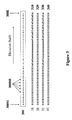
- FIG. 3 illustrates half of an elevation bias pattern and the corresponding phases of harmonic waveforms for an embodiment of the present invention
- FIG. 4 depicts half of a bias pattern according to an embodiment of the present invention applied to suppress the fundamental and odd harmonics
- FIG. 5 illustrates a firing sequence for an embodiment of the present invention
- FIGS. 6A-6C illustrate the harmonic components transmitted and received by the first through third, respectively, firings as shown in FIG. 5 ;
- FIG. 7 illustrates a firing sequence for an embodiment of the present invention to improve sidelobe elevation focus
- FIG. 8 illustrates a firing sequence for an embodiment of the present invention to improve focus in elevation
- FIG. 9 illustrates compounding with two different elevation vectors according to an embodiment of the present invention.
- FIG. 1 illustrates the concepts of the present invention.
- the invention in its most general form comprises combining data received from multiple transmit-receive events to form a single output waveform.
- each transmit and receive event can have, among other characteristics, a unique transmit bias pattern, a unique receive bias pattern, a unique transmit signal, and a unique receive signal processing algorithm.
- the voltage magnitude of the bias patterns will depend on the requirements of the precise design employed.
- the voltage magnitude of a bias is desired to be as large as possible without leading to the phenomenon known in the art as diaphragm pinning (i.e., also know as touch-down, pull-in, or collapse), which is application dependent. While it will become apparent to those skilled in the art that the invented scheme described in the present application can be used for many applications, only the embodiments relevant to the leading applications are described herein.
- the present invention uses a cMUT array having individually addressable DC bias lines running orthogonally to the transducer elements.
- transducer elements are made up of individual transducer cells and groups of elements form the cMUT array.
- the transducer elements can form columns in the elevation direction and the side-by-side elements can form the cMUT array along the azimuth direction.
- This specific transducer design is fully disclosed in commonly owned U.S. patent application Ser. No. 10/367,106 filed Feb. 14, 2003.
- the present invention provides, among other aspects, a new way to control and process the bias profile of such a cMUT array over the course of multiple firings so as to make the cMUT suitable for use in harmonic imaging.
- a first embodiment of the present invention provides a technique to subtract out harmonic distortion arising from the non-linear behavior of a cMUT. This is accomplished through manipulation of the transducer element's elevation bias patterns over a series of sequential firings in such a way that the-combination (e.g., the weighted sum) of these firings causes the non-linear components in the cMUT's pressure output to cancel.
- the series of sequential firings occurs on the transducer element for the same image area, in this example, the same elevation image slice.
- Such elimination of generated harmonics greatly improves the quality of tissue-generated or contrast-agent-generated harmonic images made with a cMUT.
- the present invention achieves this improvement in harmonic performance without the necessity of having arbitrary radio frequency (RF) waveform generator capability in the ultrasound imaging system.
- RF radio frequency
- FIG. 2 illustrates the nonlinear nature of a simulated cMUT when large pressure outputs from the transducer are required.
- the cMUT is excited by a 10 MHz, linear, 6-cycle sinusoidal voltage added to a DC bias of about 70 Volts in magnitude.
- the top chart 210 of FIG. 2 shows the pressure output. from the cMUT when the DC bias voltage polarity is positive (+70 Volts).
- the middle chart 220 of FIG. 2 shows the cMUT's pressure output from the same forcing function, but where the DC bias voltage polarity is negative ( ⁇ 70 Volts).
- 2 is the result of combining the output values of the top chart 210 to the output values of the middle chart 220 .
- the 2 f harmonic (20 MHz) is clearly visible in the bottom chart 230 , while the 1 f fundamental frequency (10 MHz) is absent. This happens because inverting the DC bias voltage polarity from 210 to 220 inverts the 1 f fundamental component, but leaves the 2 f harmonic component unchanged.
- FIG. 3 illustrates the transmit pressure behavior of a cMUT array with a bias profile designed to produce an elevation focus at 20 mm depth. Focusing in elevation is defined as the “standard mode of operation” for such a cMUT array. Only half of the transducer element elevation bias profile 300 is shown, 300 M being the midpoint in the elevation direction, and 300 E being one of the edges (the other half of the profile is identical to the half shown, without repeating the midpoint 300 M).
- phase of the pressure output (relative to the pressure output of a positively biased fundamental) corresponding to each bias-block 300 BB along the half-elevation, repeated for 4 harmonic components 1 f 310 , 2 f 320 , 3 f 330 , and 4 f 340 .
- 1 f 310 is the fundamental linear component of the cMUT pressure output
- 2 f 320 , 3 f 330 , and 4 f 340 are the harmonic components arising from the non-linear nature of the cMUT.
- Significance to the present invention is the fact that all odd transmitted harmonic components (e.g., 1 f 310 and 3 f 330 ) have bias-block phases that track the polarity of the applied DC bias voltage, while all even transmitted harmonic components (e.g., 2 f 320 and 4 f 340 ) have a constant phase that is independent of the applied DC bias voltage.
- FIG. 4 illustrates the behavior of a cMUT array with an “alternating” bias profile 400 designed to suppress radiation of the fundamental mode (and more generally, radiation of all odd harmonic frequencies).
- a bias profile 400 is characterized by adjacent regions of opposite bias polarity that are spaced as finely as allowed by the bias-blocks 400 BB. Only half of the transducer element elevation bias profile 400 is shown, 400 M being the midpoint in the elevation direction, and 400 E being one of the edges (the other half of the profile is identical to the half shown, without repeating the midpoint 400 M).
- phase profiles highlight an important aspect of this embodiment of the present invention. Specifically, those phase profiles that alternate between 0 and ⁇ from bias-block to bias-block prevent the corresponding frequency component from radiating into the field, provided that the pitch between adjacent bias blocks is smaller than one wavelength at that fundamental frequency. As is apparent from FIG. 4 , even harmonic components (e.g., 2 f 420 and 4 f 440 ) radiate, while odd harmonic components (e.g., 1 f 410 and 3 f 430 ) do not.
- FIG. 5 depicts the bias profiles used for both transmit (T) and receive (R) in the sequence of three consecutive firings 510 , 520 , 530 that make up another embodiment of the present invention.
- the cMUT array is operated in standard transmit mode 510 T with a conventional elevation focus (in this case, at 20 mm depth, as discussed in relation to FIG. 3 ) optimized for 1 f frequencies.
- the bias pattern is switched to the first firing receive bias pattern 510 R before any echoes are received.
- the first firing receive bias pattern 510 R is a conventional elevation focus optimized for 2 f frequencies.
- transmit bias pattern 520 T which is the polarity inverse of the transmit pattern used in the first firing 510 , and uses the same receive bias pattern 520 R as the first firing 510 receive bias pattern 510 R. Inverting the second firing 520 transmit bias pattern 520 T causes the fundamental frequency and all odd generated harmonics in the second firing 520 to invert relative to their counterparts in the first firing 510 . In all other respects, the first firing 510 and the second firing 520 are identical.
- the cMUT array is operated in an alternating bias polarity profile mode on transmit 530 T, which results in the suppression of the fundamental frequency and all odd generated harmonics. More specifically, in the third firing 530 , only the even generated harmonics are transmitted into the transmission medium.
- the receive bias pattern 530 R of the third firing 530 is identical to the bias polarity patterns used on receive in the previous two firings 510 , 520 .
- FIG. 6A shows a detailed view of the harmonic components transmitted and received during the first firing 510 of FIG. 5 .
- Transmitted components for the first firing 510 are shown in the upper half of FIG. 6A .
- the largest component of the cMUT's pressure output is the transmitted fundamental frequency 610 , which is focused in elevation.
- the transmitted harmonic components 612 are generated internally to the cMUT due to its non-linear nature. Both the frequency and relative phase are shown for all the transmitted components 610 , 612 .
- Received components for the first firing 510 are shown in the lower half of FIG. 6A .
- the received components created by echoes off tissue structure 615 and the received components arising from non-linear generation in the tissue 617 are shown. Again, as before, both the frequency and relative phase for each of these received components 615 , 617 are shown.
- FIG. 6B shows the same information for the second firing 520 of FIG. 5 that FIG. 6A shows for the first firing 510 of FIG. 5 .
- the transmitted fundamental frequency 620 in the second firing 520 and the transmitted harmonic components 622 that are generated internally in the cMUT are shown. Note that all of the transmitted odd harmonic components have a phase of ⁇ (relative to those same components of the first firing 510 ), while all the transmitted even harmonic components have the same phase as their first firing 510 equivalents.
- Received components 625 , 627 for the second firing 520 are shown in the lower half of FIG. 6B .
- Received components 625 represent those received components created by echoes off tissue structure. The relative phases of these received components 625 are preserved from the phases present at the time of firing.
- Received components 627 represent those received components arising from non-linear generation in the tissue. Note that the 2 f and 4 f components in received components 627 have the same phase as their counterparts in the first firing 520 (e.g., FIG. 6A , 617 ). This is because generation of the 2 f harmonic in tissue is insensitive to phase shifts of ⁇ N ⁇ in the fundamental frequency source waveform.
- FIG. 6C illustrates a detailed view of the harmonic components transmitted and received during third firing 530 of FIG. 5 .
- the absence of a transmitted fundamental frequency component 630 is consistent with the expected behavior of the alternating bias profile used in the third firing 530 .
- the transmitted harmonic components 632 are generated internally in the cMUT. Note that only even harmonic components are present and those components have the same phase as their counterparts in the first two firings 510 , 520 .
- Received components for the third firing 530 are shown in the lower half of FIG. 6C . In the received components 635 , only even harmonic frequency components from tissue echoes are received. Of significance is the fact that no 2 f harmonics are generated in the tissue due to the absence of the transmitted fundamental frequency component 630 , and none therefore are received 637 during the third firing 530 .
- F 1 +F 2 ⁇ (2 *F 3) [tissue-generated harmonics only], where F 1 is the received voltage vs. time data from the first firing 510 of FIG. 5 , F 2 is the received voltage vs. time data from the second firing 520 , and F 3 is the received voltage vs. time data from the third firing 530 .
- F 1 is the received voltage vs. time data from the first firing 510 of FIG. 5
- F 2 is the received voltage vs. time data from the second firing 520
- F 3 is the received voltage vs. time data from the third firing 530 .
- the present invention is not limited to the specific sequence, composition, and combination of firings outlined in FIGS. 5-6 .
- those skilled in the art will understand that there are many different variations of transmit and receive bias patterns, firing sequences, and summing coefficients that will allow for the isolation of tissue or contrast generated harmonics and exclusion of cMUT-generated harmonics.
- inverting, phase shifting, or otherwise altering the RF signal supplied to the cMUT element may be used in conjunction with bias pattern inversions to achieve the same result.
- bias pattern inversions to achieve the same result.
- the firing commonly referred to as the third firing 530 may not be necessary to the extent that the cMUT-generated harmonics are sufficiently small or dispersed compared to the harmonics generated in the tissue.
- a simple two-firing scheme could be used in conjunction with a cMUT array having a single controllable set of bias lines in elevation as a way to do harmonic imaging without requiring the RF waveform be inverted, phase shifted, or otherwise altered between the two firings.
- FIG. 7 which demonstrates a method to reduce the high sidelobe present in the near field of a single firing 700 .
- Multiple firings 710 , 720 can be combined 730 with separate transmit and receive biases to improve main lobe or side lobe characteristics.
- FIG. 8 illustrates how the elevation focus of a single firing 800 can be improved by two firings 810 , 820 that are summed with a + ⁇ /2 phase shift.
- the single firing 800 is broken up into regions of ‘+’ 830 A, regions of ‘ ⁇ ’ 830 C, regions of ‘transition’ 830 B, 830 D and regions of ‘off’ 830 E.
- first firing 810 of the multiple firing scheme original regions of ‘+’ 830 A and ‘ ⁇ ’ 830 C are preserved, and the regions of ‘transition’ 830 B, 830 D are effectively turned off by finely alternating the bias polarity in those same locations.
- the received waveforms from the first firing 810 and the second 820 are summed, but only after a phase shift of + ⁇ /2 is applied to the second firing 820 .
- This summing of the waveforms one quarter wavelength out of phase yields a quantized phase set ⁇ 0, ⁇ /2, ⁇ , and 3 ⁇ /2 ⁇ , as compared to the binary phase set ⁇ 0, ⁇ characteristic of the single firing 900 case.
- This enlarged quantized phase set allows for more precise phase contouring across the elevation of the cMUT element, and consequently, an improved elevation focus in the field.
- phase delay described above can also be applied to transmit signal instead of the received signal.
- time delay could be used.
- bias patterns may be used in two or more firings, and the received signals from these firings may be combined in many different ways. Also, use of dissimilar RF signals in each firing may be used in conjunction with alterations in bias pattern. This same technique can also be used to steer the beam by a small angle in the elevation direction.
- FIG. 9 An implementation of this aspect of the present invention is illustrated in FIG. 9 .
- a first vector 910 is fired, and the received data are acquired, magnitude detected and stored.
- a second vector 920 that is slightly shifted in elevation plane is fired. This elevation plane shift can be achieved just shifting the bias pattern as previously described.
- the received data from the second vector 920 is magnitude detected and combined with the first vector 910 stored data. This results in a compounded image that has reduced speckle.
- the shift between the two vectors 910 , 920 should be large enough to provide speckle de-correlation and small enough not to degrade the elevation slice thickness.
- the gap between the two vectors 910 , 920 depends upon the speckle correlation length and the desired amount of speckle compounding.
- the gap between two compounding vectors would also depend upon how much elevation slice thickness degradation can be tolerated in the image. As an example, the gap could be the same as the ⁇ 6 dB elevation beam width of the imaging setup, or approximately 1 mm for a 9 MHz probe.
- Compounding can also be applied to combine two or more firings that are focused at different ranges.
- the bias pattern applied to a transducer array is periodically inverted in order to remove or delay the deleterious effects that high electric fields can have on insulators.
- the bias pattern switching may have no effect on the focusing of the transducer.
- that polarity, and any other polarities spatially distributed across the transducer can be inverted at a frequency of at least 1 Hz.
- a 1 Hz oscillation of bias voltage is adequate.
- faster or slower inversion rates may be necessary for different insulator and material systems. As long as the inversion frequency is relatively slow compared to imaging functions, the inversion can occur at a brief interval of time in such a manner that it does not materially impact imaging frame rate.
Abstract
Description
F1+F2−(2*F3)=[tissue-generated harmonics only],
where F1 is the received voltage vs. time data from the
Claims (57)
Priority Applications (3)
| Application Number | Priority Date | Filing Date | Title |
|---|---|---|---|
| US10/819,094 US7780597B2 (en) | 2003-02-14 | 2004-04-05 | Method and apparatus for improving the performance of capacitive acoustic transducers using bias polarity control and multiple firings |
| US10/959,665 US7618373B2 (en) | 2003-02-14 | 2004-10-04 | Microfabricated ultrasonic transducer array for 3-D imaging and method of operating the same |
| US10/958,626 US7635332B2 (en) | 2003-02-14 | 2004-10-04 | System and method of operating microfabricated ultrasonic transducers for harmonic imaging |
Applications Claiming Priority (3)
| Application Number | Priority Date | Filing Date | Title |
|---|---|---|---|
| US10/367,106 US7087023B2 (en) | 2003-02-14 | 2003-02-14 | Microfabricated ultrasonic transducers with bias polarity beam profile control and method of operating the same |
| US46063803P | 2003-04-04 | 2003-04-04 | |
| US10/819,094 US7780597B2 (en) | 2003-02-14 | 2004-04-05 | Method and apparatus for improving the performance of capacitive acoustic transducers using bias polarity control and multiple firings |
Related Parent Applications (1)
| Application Number | Title | Priority Date | Filing Date |
|---|---|---|---|
| US10/367,106 Continuation-In-Part US7087023B2 (en) | 2003-02-14 | 2003-02-14 | Microfabricated ultrasonic transducers with bias polarity beam profile control and method of operating the same |
Related Child Applications (2)
| Application Number | Title | Priority Date | Filing Date |
|---|---|---|---|
| US10/958,626 Continuation-In-Part US7635332B2 (en) | 2003-02-14 | 2004-10-04 | System and method of operating microfabricated ultrasonic transducers for harmonic imaging |
| US10/959,665 Continuation-In-Part US7618373B2 (en) | 2003-02-14 | 2004-10-04 | Microfabricated ultrasonic transducer array for 3-D imaging and method of operating the same |
Publications (2)
| Publication Number | Publication Date |
|---|---|
| US20060173342A1 US20060173342A1 (en) | 2006-08-03 |
| US7780597B2 true US7780597B2 (en) | 2010-08-24 |
Family
ID=36757565
Family Applications (1)
| Application Number | Title | Priority Date | Filing Date |
|---|---|---|---|
| US10/819,094 Expired - Fee Related US7780597B2 (en) | 2003-02-14 | 2004-04-05 | Method and apparatus for improving the performance of capacitive acoustic transducers using bias polarity control and multiple firings |
Country Status (1)
| Country | Link |
|---|---|
| US (1) | US7780597B2 (en) |
Cited By (6)
| Publication number | Priority date | Publication date | Assignee | Title |
|---|---|---|---|---|
| US20090079299A1 (en) * | 2007-09-26 | 2009-03-26 | Bradley Charles E | Aperture synthesis using cMUTs |
| US20110016977A1 (en) * | 2009-07-22 | 2011-01-27 | Siemens Medical Solutions Usa, Inc. | Scan Patterns for Electronically Positioned Apertures on an Array |
| US20140219059A1 (en) * | 2013-02-06 | 2014-08-07 | Babcock & Wilcox Technical Services Group, Inc. | Synthetic data collection method for full matrix capture using an ultrasound array |
| US10754016B1 (en) | 2017-03-03 | 2020-08-25 | White Eagle Sonic Technologies, Inc. | Systems and methods for ultrasound phase adjustment |
| US11061124B2 (en) | 2016-10-21 | 2021-07-13 | The Governors Of The University Of Alberta | System and method for ultrasound imaging |
| US11150344B2 (en) | 2018-01-26 | 2021-10-19 | Roger Zemp | 3D imaging using a bias-sensitive crossed-electrode array |
Families Citing this family (20)
| Publication number | Priority date | Publication date | Assignee | Title |
|---|---|---|---|---|
| US7635332B2 (en) * | 2003-02-14 | 2009-12-22 | Siemens Medical Solutions Usa, Inc. | System and method of operating microfabricated ultrasonic transducers for harmonic imaging |
| US7618373B2 (en) * | 2003-02-14 | 2009-11-17 | Siemens Medical Solutions Usa, Inc. | Microfabricated ultrasonic transducer array for 3-D imaging and method of operating the same |
| EP1515158B1 (en) * | 2003-09-09 | 2013-07-17 | Esaote S.p.A. | Ultrasound imaging method combined with the presence of contrast media in the body under examination |
| US20050215909A1 (en) * | 2004-03-19 | 2005-09-29 | Siemens Medical Solutions Usa, Inc. | Electric field control for capacitive micromachined ultrasound transducers |
| US8465431B2 (en) * | 2005-12-07 | 2013-06-18 | Siemens Medical Solutions Usa, Inc. | Multi-dimensional CMUT array with integrated beamformation |
| US7963919B2 (en) | 2005-12-07 | 2011-06-21 | Siemens Medical Solutions Usa, Inc. | Ultrasound imaging transducer array for synthetic aperture |
| US7956510B2 (en) * | 2006-04-04 | 2011-06-07 | Kolo Technologies, Inc. | Modulation in micromachined ultrasonic transducers |
| EP1944070A1 (en) * | 2007-01-12 | 2008-07-16 | Esaote S.p.A. | Bidimensional ultrasonic array for volumetric imaging |
| CN101874312B (en) * | 2007-12-03 | 2014-06-11 | 科隆科技公司 | Variable operating voltage in micromachined ultrasonic transducer |
| EP2223654A4 (en) * | 2007-12-13 | 2017-09-06 | Hitachi, Ltd. | Ultrasonic diagnostic equipment and ultrasonic probe |
| EP2120064A1 (en) * | 2008-05-02 | 2009-11-18 | INSERM (Institut National de la Santé et de la Recherche Médicale) | A method for compensating a harmonic component of an emitted ultrasound wave |
| US8133182B2 (en) | 2008-09-09 | 2012-03-13 | Siemens Medical Solutions Usa, Inc. | Multi-dimensional transducer array and beamforming for ultrasound imaging |
| EP2866668B1 (en) * | 2012-06-28 | 2021-09-08 | B-K Medical ApS | Ultrasound imaging |
| CA2795441A1 (en) * | 2012-10-19 | 2014-04-19 | The Governors Of The University Of Alberta | Top-orthogonal-to-bottom electrode (tobe) 2d cmut arrays for low-channel-count 3d imaging |
| FR3019906A1 (en) * | 2014-04-11 | 2015-10-16 | Univ Tours Francois Rabelais | METHOD FOR CONTROLLING CMUT TRANSDUCERS IN HARMONIC ECHOGRAPHY, AND IN PARTICULAR CONTRAST |
| US11712221B2 (en) | 2016-06-20 | 2023-08-01 | Bfly Operations, Inc. | Universal ultrasound device and related apparatus and methods |
| US10856840B2 (en) | 2016-06-20 | 2020-12-08 | Butterfly Network, Inc. | Universal ultrasound device and related apparatus and methods |
| EP4289521A3 (en) * | 2016-12-22 | 2024-03-27 | Koninklijke Philips N.V. | Systems and methods of operation of capacitive radio frequency micro-electromechanical switches |
| EP3435116A1 (en) * | 2017-07-24 | 2019-01-30 | Koninklijke Philips N.V. | An ultrasound probe and processing method |
| JP7302163B2 (en) * | 2018-11-22 | 2023-07-04 | コニカミノルタ株式会社 | ULTRASOUND DIAGNOSTIC APPARATUS AND ULTRASOUND IMAGE GENERATING METHOD |
Citations (56)
| Publication number | Priority date | Publication date | Assignee | Title |
|---|---|---|---|---|
| US2999986A (en) | 1957-12-13 | 1961-09-12 | Holbrook George William | Method of correcting non-linear distortion |
| US4145931A (en) | 1978-01-03 | 1979-03-27 | Raytheon Company | Fresnel focussed imaging system |
| US4341120A (en) | 1979-11-09 | 1982-07-27 | Diasonics Cardio/Imaging, Inc. | Ultrasonic volume measuring system |
| DE3219223A1 (en) | 1982-05-21 | 1983-11-24 | Siemens AG, 1000 Berlin und 8000 München | Device for ultrasonic scanning |
| US4670683A (en) | 1985-08-20 | 1987-06-02 | North American Philips Corporation | Electronically adjustable mechanical lens for ultrasonic linear array and phased array imaging |
| US4694434A (en) | 1984-06-12 | 1987-09-15 | Von Ramm Olaf T | Three-dimensional imaging system |
| US4736630A (en) | 1985-08-05 | 1988-04-12 | Hitachi, Ltd. | Apparatus and method for sending out and receiving ultrasonic wave signals |
| US4888746A (en) | 1987-09-24 | 1989-12-19 | Richard Wolf Gmbh | Focussing ultrasound transducer |
| US5229933A (en) | 1989-11-28 | 1993-07-20 | Hewlett-Packard Company | 2-d phased array ultrasound imaging system with distributed phasing |
| US5233993A (en) | 1990-11-19 | 1993-08-10 | Hitachi Medical Corporation | Ultrasonic diagnostic apparatus and image forming method therefor |
| US5301168A (en) | 1993-01-19 | 1994-04-05 | Hewlett-Packard Company | Ultrasonic transducer system |
| US5415175A (en) | 1993-09-07 | 1995-05-16 | Acuson Corporation | Broadband phased array transducer design with frequency controlled two dimension capability and methods for manufacture thereof |
| US5490512A (en) | 1994-06-16 | 1996-02-13 | Siemens Medical Systems, Inc. | Elevation direction focusing in ultrasound transducer arrays |
| US5619476A (en) * | 1994-10-21 | 1997-04-08 | The Board Of Trustees Of The Leland Stanford Jr. Univ. | Electrostatic ultrasonic transducer |
| US5627580A (en) | 1993-07-26 | 1997-05-06 | Texas Instruments Incorporated | System and method for enhanced printing |
| US5632277A (en) | 1996-06-28 | 1997-05-27 | Siemens Medical Systems, Inc. | Ultrasound imaging system employing phase inversion subtraction to enhance the image |
| US5651365A (en) | 1995-06-07 | 1997-07-29 | Acuson Corporation | Phased array transducer design and method for manufacture thereof |
| US5671746A (en) | 1996-07-29 | 1997-09-30 | Acuson Corporation | Elevation steerable ultrasound transducer array |
| US5706819A (en) | 1995-10-10 | 1998-01-13 | Advanced Technology Laboratories, Inc. | Ultrasonic diagnostic imaging with harmonic contrast agents |
| US5768007A (en) | 1995-09-11 | 1998-06-16 | Texas Instruments Incorporated | Phase matched reset for digital micro-mirror device |
| US5894452A (en) * | 1994-10-21 | 1999-04-13 | The Board Of Trustees Of The Leland Stanford Junior University | Microfabricated ultrasonic immersion transducer |
| US5902243A (en) | 1998-04-15 | 1999-05-11 | Acuson Corporation | Ultrasonic imaging method with multiple pulse cancellation |
| US5944666A (en) * | 1997-08-21 | 1999-08-31 | Acuson Corporation | Ultrasonic method for imaging blood flow including disruption or activation of contrast agent |
| US5961463A (en) | 1998-08-24 | 1999-10-05 | General Electric Company | Nonlinear imaging using orthogonal transmit and receive codes |
| US5982709A (en) * | 1998-03-31 | 1999-11-09 | The Board Of Trustees Of The Leland Stanford Junior University | Acoustic transducers and method of microfabrication |
| EP0978822A2 (en) | 1998-08-03 | 2000-02-09 | Vingmed Sound A/S | A multi-dimensional transducer array apparatus |
| WO2000030543A1 (en) | 1998-11-19 | 2000-06-02 | Acuson Corporation | Diagnostic medical ultrasound systems and transducers utilizing micro-mechanical components |
| US6104670A (en) * | 1995-03-02 | 2000-08-15 | Acuson Corporation | Ultrasonic harmonic imaging system and method |
| US6102860A (en) | 1998-12-24 | 2000-08-15 | Agilent Technologies, Inc. | Ultrasound transducer for three-dimensional imaging |
| US6108572A (en) * | 1998-03-31 | 2000-08-22 | General Electric Company | Method and apparatus for harmonic imaging using multiple focal zones |
| US6122223A (en) * | 1995-03-02 | 2000-09-19 | Acuson Corporation | Ultrasonic transmit waveform generator |
| US6126602A (en) | 1998-05-28 | 2000-10-03 | Agilent Technologies, Inc. | Phased array acoustic systems with intra-group processors |
| US6159153A (en) | 1998-12-31 | 2000-12-12 | Duke University | Methods and systems for ultrasound scanning using spatially and spectrally separated transmit ultrasound beams |
| US6172797B1 (en) * | 1995-06-19 | 2001-01-09 | Reflectivity, Inc. | Double substrate reflective spatial light modulator with self-limiting micro-mechanical elements |
| US6186950B1 (en) | 1999-11-04 | 2001-02-13 | Atl Ultrasound | Ultrasonic pulse inversion harmonic separation with reduced motional effects |
| US6246158B1 (en) * | 1999-06-24 | 2001-06-12 | Sensant Corporation | Microfabricated transducers formed over other circuit components on an integrated circuit chip and methods for making the same |
| US6271620B1 (en) * | 1999-05-20 | 2001-08-07 | Sen Corporation | Acoustic transducer and method of making the same |
| US6292435B1 (en) * | 1999-05-11 | 2001-09-18 | Agilent Technologies, Inc. | Circuit and method for exciting a micro-machined transducer to have low second order harmonic transmit energy |
| US6328697B1 (en) * | 2000-06-15 | 2001-12-11 | Atl Ultrasound, Inc. | Capacitive micromachined ultrasonic transducers with improved capacitive response |
| US6381197B1 (en) * | 1999-05-11 | 2002-04-30 | Bernard J Savord | Aperture control and apodization in a micro-machined ultrasonic transducer |
| US6425869B1 (en) | 2000-07-18 | 2002-07-30 | Koninklijke Philips Electronics, N.V. | Wideband phased-array transducer for uniform harmonic imaging, contrast agent detection, and destruction |
| US6436046B1 (en) * | 1997-12-18 | 2002-08-20 | Acuson Corporation | Diagnostic ultrasound imaging method and system with improved frame rate |
| US6461299B1 (en) * | 1999-12-22 | 2002-10-08 | Acuson Corporation | Medical diagnostic ultrasound system and method for harmonic imaging with an electrostatic transducer |
| US6491631B2 (en) * | 2001-01-11 | 2002-12-10 | General Electric Company | Harmonic golay-coded excitation with differential pulsing for diagnostic ultrasound imaging |
| US6527723B2 (en) | 2001-06-26 | 2003-03-04 | Koninklijke Philips Electronics N.V. | Variable multi-dimensional apodization control for ultrasonic transducers |
| US20030048698A1 (en) * | 2001-09-07 | 2003-03-13 | Siemens Medical Systems, Inc. | Bias control of electrostatic transducers |
| US6551248B2 (en) * | 2001-07-31 | 2003-04-22 | Koninklijke Philips Electronics N.V. | System for attaching an acoustic element to an integrated circuit |
| US6645145B1 (en) | 1998-11-19 | 2003-11-11 | Siemens Medical Solutions Usa, Inc. | Diagnostic medical ultrasound systems and transducers utilizing micro-mechanical components |
| US6656123B2 (en) * | 2001-12-19 | 2003-12-02 | Koninklijke Philips Electronics N.V. | Combined fundamental and harmonic ultrasonic imaging at low MI or deeper depths |
| US6676602B1 (en) | 2002-07-25 | 2004-01-13 | Siemens Medical Solutions Usa, Inc. | Two dimensional array switching for beamforming in a volume |
| US6709395B2 (en) | 2002-06-25 | 2004-03-23 | Koninklijke Philips Electronics N.V. | System and method for electronically altering ultrasound scan line origin for a three-dimensional ultrasound system |
| US6749570B2 (en) | 2002-08-23 | 2004-06-15 | Acuson Corporation | Ultrasound method and apparatus for imaging breast |
| WO2004075165A1 (en) | 2003-02-14 | 2004-09-02 | Sensant Corporation | Microfabricated ultrasonic transducers with bias polarity beam profile control |
| US20050119575A1 (en) | 2003-02-14 | 2005-06-02 | Igal Ladabaum | Microfabricated ultrasonic transducer array for 3-D imaging and method of operating the same |
| US7311667B2 (en) | 2002-09-09 | 2007-12-25 | Siemens Medical Solutions Usa, Inc. | Multiple pattern transducer array and method of use |
| US7508113B2 (en) | 2004-05-18 | 2009-03-24 | Siemens Medical Solutions Usa, Inc. | Apparatus for two-dimensional transducers used in three-dimensional ultrasonic imaging |
-
2004
- 2004-04-05 US US10/819,094 patent/US7780597B2/en not_active Expired - Fee Related
Patent Citations (65)
| Publication number | Priority date | Publication date | Assignee | Title |
|---|---|---|---|---|
| US2999986A (en) | 1957-12-13 | 1961-09-12 | Holbrook George William | Method of correcting non-linear distortion |
| US4145931A (en) | 1978-01-03 | 1979-03-27 | Raytheon Company | Fresnel focussed imaging system |
| US4341120A (en) | 1979-11-09 | 1982-07-27 | Diasonics Cardio/Imaging, Inc. | Ultrasonic volume measuring system |
| DE3219223A1 (en) | 1982-05-21 | 1983-11-24 | Siemens AG, 1000 Berlin und 8000 München | Device for ultrasonic scanning |
| US4694434A (en) | 1984-06-12 | 1987-09-15 | Von Ramm Olaf T | Three-dimensional imaging system |
| US4736630A (en) | 1985-08-05 | 1988-04-12 | Hitachi, Ltd. | Apparatus and method for sending out and receiving ultrasonic wave signals |
| US4670683A (en) | 1985-08-20 | 1987-06-02 | North American Philips Corporation | Electronically adjustable mechanical lens for ultrasonic linear array and phased array imaging |
| US4888746A (en) | 1987-09-24 | 1989-12-19 | Richard Wolf Gmbh | Focussing ultrasound transducer |
| US5229933A (en) | 1989-11-28 | 1993-07-20 | Hewlett-Packard Company | 2-d phased array ultrasound imaging system with distributed phasing |
| US5233993A (en) | 1990-11-19 | 1993-08-10 | Hitachi Medical Corporation | Ultrasonic diagnostic apparatus and image forming method therefor |
| US5301168A (en) | 1993-01-19 | 1994-04-05 | Hewlett-Packard Company | Ultrasonic transducer system |
| US5627580A (en) | 1993-07-26 | 1997-05-06 | Texas Instruments Incorporated | System and method for enhanced printing |
| US5415175A (en) | 1993-09-07 | 1995-05-16 | Acuson Corporation | Broadband phased array transducer design with frequency controlled two dimension capability and methods for manufacture thereof |
| US5490512A (en) | 1994-06-16 | 1996-02-13 | Siemens Medical Systems, Inc. | Elevation direction focusing in ultrasound transducer arrays |
| US5870351A (en) * | 1994-10-21 | 1999-02-09 | The Board Of Trustees Of The Leland Stanford Junior University | Broadband microfabriated ultrasonic transducer and method of fabrication |
| US5619476A (en) * | 1994-10-21 | 1997-04-08 | The Board Of Trustees Of The Leland Stanford Jr. Univ. | Electrostatic ultrasonic transducer |
| US6004832A (en) * | 1994-10-21 | 1999-12-21 | The Board Of Trustees Of The Leland Stanford Junior University | Method of fabricating an electrostatic ultrasonic transducer |
| US5894452A (en) * | 1994-10-21 | 1999-04-13 | The Board Of Trustees Of The Leland Stanford Junior University | Microfabricated ultrasonic immersion transducer |
| US6104670A (en) * | 1995-03-02 | 2000-08-15 | Acuson Corporation | Ultrasonic harmonic imaging system and method |
| US6122223A (en) * | 1995-03-02 | 2000-09-19 | Acuson Corporation | Ultrasonic transmit waveform generator |
| US5651365A (en) | 1995-06-07 | 1997-07-29 | Acuson Corporation | Phased array transducer design and method for manufacture thereof |
| US6172797B1 (en) * | 1995-06-19 | 2001-01-09 | Reflectivity, Inc. | Double substrate reflective spatial light modulator with self-limiting micro-mechanical elements |
| US5768007A (en) | 1995-09-11 | 1998-06-16 | Texas Instruments Incorporated | Phase matched reset for digital micro-mirror device |
| US5951478A (en) | 1995-10-10 | 1999-09-14 | Advanced Technology Laboratories, Inc. | Two pulse technique for ultrasonic harmonic imaging |
| US5706819A (en) | 1995-10-10 | 1998-01-13 | Advanced Technology Laboratories, Inc. | Ultrasonic diagnostic imaging with harmonic contrast agents |
| US5632277A (en) | 1996-06-28 | 1997-05-27 | Siemens Medical Systems, Inc. | Ultrasound imaging system employing phase inversion subtraction to enhance the image |
| US5671746A (en) | 1996-07-29 | 1997-09-30 | Acuson Corporation | Elevation steerable ultrasound transducer array |
| US5944666A (en) * | 1997-08-21 | 1999-08-31 | Acuson Corporation | Ultrasonic method for imaging blood flow including disruption or activation of contrast agent |
| US5947904A (en) * | 1997-08-21 | 1999-09-07 | Acuson Corporation | Ultrasonic method and system for imaging blood flow including disruption or activation of a contrast agent |
| US6436046B1 (en) * | 1997-12-18 | 2002-08-20 | Acuson Corporation | Diagnostic ultrasound imaging method and system with improved frame rate |
| US6108572A (en) * | 1998-03-31 | 2000-08-22 | General Electric Company | Method and apparatus for harmonic imaging using multiple focal zones |
| US5982709A (en) * | 1998-03-31 | 1999-11-09 | The Board Of Trustees Of The Leland Stanford Junior University | Acoustic transducers and method of microfabrication |
| US5902243A (en) | 1998-04-15 | 1999-05-11 | Acuson Corporation | Ultrasonic imaging method with multiple pulse cancellation |
| US6126602A (en) | 1998-05-28 | 2000-10-03 | Agilent Technologies, Inc. | Phased array acoustic systems with intra-group processors |
| EP0978822A2 (en) | 1998-08-03 | 2000-02-09 | Vingmed Sound A/S | A multi-dimensional transducer array apparatus |
| US5961463A (en) | 1998-08-24 | 1999-10-05 | General Electric Company | Nonlinear imaging using orthogonal transmit and receive codes |
| US6645145B1 (en) | 1998-11-19 | 2003-11-11 | Siemens Medical Solutions Usa, Inc. | Diagnostic medical ultrasound systems and transducers utilizing micro-mechanical components |
| WO2000030543A1 (en) | 1998-11-19 | 2000-06-02 | Acuson Corporation | Diagnostic medical ultrasound systems and transducers utilizing micro-mechanical components |
| US6102860A (en) | 1998-12-24 | 2000-08-15 | Agilent Technologies, Inc. | Ultrasound transducer for three-dimensional imaging |
| US6159153A (en) | 1998-12-31 | 2000-12-12 | Duke University | Methods and systems for ultrasound scanning using spatially and spectrally separated transmit ultrasound beams |
| US6381197B1 (en) * | 1999-05-11 | 2002-04-30 | Bernard J Savord | Aperture control and apodization in a micro-machined ultrasonic transducer |
| US6292435B1 (en) * | 1999-05-11 | 2001-09-18 | Agilent Technologies, Inc. | Circuit and method for exciting a micro-machined transducer to have low second order harmonic transmit energy |
| US6271620B1 (en) * | 1999-05-20 | 2001-08-07 | Sen Corporation | Acoustic transducer and method of making the same |
| US6571445B2 (en) | 1999-05-20 | 2003-06-03 | Igal Ladabaum | Method for making acoustic transducer |
| US6246158B1 (en) * | 1999-06-24 | 2001-06-12 | Sensant Corporation | Microfabricated transducers formed over other circuit components on an integrated circuit chip and methods for making the same |
| US6562650B2 (en) | 1999-06-24 | 2003-05-13 | Sensant Corporation | Microfabricated transducers formed over other circuit components on an integrated circuit chip and methods for making the same |
| US6186950B1 (en) | 1999-11-04 | 2001-02-13 | Atl Ultrasound | Ultrasonic pulse inversion harmonic separation with reduced motional effects |
| US6461299B1 (en) * | 1999-12-22 | 2002-10-08 | Acuson Corporation | Medical diagnostic ultrasound system and method for harmonic imaging with an electrostatic transducer |
| US6328697B1 (en) * | 2000-06-15 | 2001-12-11 | Atl Ultrasound, Inc. | Capacitive micromachined ultrasonic transducers with improved capacitive response |
| US6443901B1 (en) | 2000-06-15 | 2002-09-03 | Koninklijke Philips Electronics N.V. | Capacitive micromachined ultrasonic transducers |
| US6425869B1 (en) | 2000-07-18 | 2002-07-30 | Koninklijke Philips Electronics, N.V. | Wideband phased-array transducer for uniform harmonic imaging, contrast agent detection, and destruction |
| US6491631B2 (en) * | 2001-01-11 | 2002-12-10 | General Electric Company | Harmonic golay-coded excitation with differential pulsing for diagnostic ultrasound imaging |
| US6527723B2 (en) | 2001-06-26 | 2003-03-04 | Koninklijke Philips Electronics N.V. | Variable multi-dimensional apodization control for ultrasonic transducers |
| US6551248B2 (en) * | 2001-07-31 | 2003-04-22 | Koninklijke Philips Electronics N.V. | System for attaching an acoustic element to an integrated circuit |
| US6795374B2 (en) * | 2001-09-07 | 2004-09-21 | Siemens Medical Solutions Usa, Inc. | Bias control of electrostatic transducers |
| US20030048698A1 (en) * | 2001-09-07 | 2003-03-13 | Siemens Medical Systems, Inc. | Bias control of electrostatic transducers |
| US6656123B2 (en) * | 2001-12-19 | 2003-12-02 | Koninklijke Philips Electronics N.V. | Combined fundamental and harmonic ultrasonic imaging at low MI or deeper depths |
| US6709395B2 (en) | 2002-06-25 | 2004-03-23 | Koninklijke Philips Electronics N.V. | System and method for electronically altering ultrasound scan line origin for a three-dimensional ultrasound system |
| US6676602B1 (en) | 2002-07-25 | 2004-01-13 | Siemens Medical Solutions Usa, Inc. | Two dimensional array switching for beamforming in a volume |
| US6749570B2 (en) | 2002-08-23 | 2004-06-15 | Acuson Corporation | Ultrasound method and apparatus for imaging breast |
| US7311667B2 (en) | 2002-09-09 | 2007-12-25 | Siemens Medical Solutions Usa, Inc. | Multiple pattern transducer array and method of use |
| WO2004075165A1 (en) | 2003-02-14 | 2004-09-02 | Sensant Corporation | Microfabricated ultrasonic transducers with bias polarity beam profile control |
| US20050119575A1 (en) | 2003-02-14 | 2005-06-02 | Igal Ladabaum | Microfabricated ultrasonic transducer array for 3-D imaging and method of operating the same |
| US7087023B2 (en) | 2003-02-14 | 2006-08-08 | Sensant Corporation | Microfabricated ultrasonic transducers with bias polarity beam profile control and method of operating the same |
| US7508113B2 (en) | 2004-05-18 | 2009-03-24 | Siemens Medical Solutions Usa, Inc. | Apparatus for two-dimensional transducers used in three-dimensional ultrasonic imaging |
Cited By (11)
| Publication number | Priority date | Publication date | Assignee | Title |
|---|---|---|---|---|
| US20090079299A1 (en) * | 2007-09-26 | 2009-03-26 | Bradley Charles E | Aperture synthesis using cMUTs |
| US8641628B2 (en) * | 2007-09-26 | 2014-02-04 | Siemens Medical Solutions Usa, Inc. | Aperture synthesis using cMUTs |
| US20110016977A1 (en) * | 2009-07-22 | 2011-01-27 | Siemens Medical Solutions Usa, Inc. | Scan Patterns for Electronically Positioned Apertures on an Array |
| US8316714B2 (en) * | 2009-07-22 | 2012-11-27 | Siemens Medical Solutions Usa, Inc. | Scan patterns for electronically positioned apertures on an array |
| US20140219059A1 (en) * | 2013-02-06 | 2014-08-07 | Babcock & Wilcox Technical Services Group, Inc. | Synthetic data collection method for full matrix capture using an ultrasound array |
| US9958420B2 (en) * | 2013-02-06 | 2018-05-01 | Bwxt Technical Services Group, Inc. | Synthetic data collection method for full matrix capture using an ultrasound array |
| US20180246069A1 (en) * | 2013-02-06 | 2018-08-30 | Bwxt Technical Services Group, Inc. | Synthetic data collection method for full matrix capture using an ultrasound array |
| US10401328B2 (en) * | 2013-02-06 | 2019-09-03 | Bwxt Technical Services, Group, Inc. | Synthetic data collection method for full matrix capture using an ultrasound array |
| US11061124B2 (en) | 2016-10-21 | 2021-07-13 | The Governors Of The University Of Alberta | System and method for ultrasound imaging |
| US10754016B1 (en) | 2017-03-03 | 2020-08-25 | White Eagle Sonic Technologies, Inc. | Systems and methods for ultrasound phase adjustment |
| US11150344B2 (en) | 2018-01-26 | 2021-10-19 | Roger Zemp | 3D imaging using a bias-sensitive crossed-electrode array |
Also Published As
| Publication number | Publication date |
|---|---|
| US20060173342A1 (en) | 2006-08-03 |
Similar Documents
| Publication | Publication Date | Title |
|---|---|---|
| US7780597B2 (en) | Method and apparatus for improving the performance of capacitive acoustic transducers using bias polarity control and multiple firings | |
| US7635332B2 (en) | System and method of operating microfabricated ultrasonic transducers for harmonic imaging | |
| US7087023B2 (en) | Microfabricated ultrasonic transducers with bias polarity beam profile control and method of operating the same | |
| US9642596B2 (en) | Ultrasound imaging apparatus | |
| JP5399632B2 (en) | Ultrasonic diagnostic equipment | |
| US7833163B2 (en) | Steering angle varied pattern for ultrasound imaging with a two-dimensional array | |
| JP2010514322A (en) | Multi-beam transmission separation | |
| US6461299B1 (en) | Medical diagnostic ultrasound system and method for harmonic imaging with an electrostatic transducer | |
| Karrer et al. | A phased array acoustic imaging system for medical use | |
| JP2006025905A (en) | Ultrasonic transmitting and receiving apparatus | |
| EP3347736B1 (en) | Systems and methods of combined phased-array and fresnel zone plate beamforming employing delay-corrected fresnel sub-apertures | |
| US7658110B2 (en) | Ultrasonic diagnostic system | |
| JP2013208295A (en) | Ultrasonic probe and ultrasonic diagnostic equipment comprising the same | |
| US5081995A (en) | Ultrasonic nondiffracting transducer | |
| EP0005071A2 (en) | Probe for electronic scanning type ultrasonic diagnostic apparatus | |
| US10613058B2 (en) | CMUT signal separation with multi-level bias control | |
| US20040193050A1 (en) | Ultrasonic transmitting and receiving apparatus | |
| Chillara et al. | Collimated acoustic beams from radial modes of piezoelectric disc transducers | |
| Latham et al. | A new 3D imaging technique integrating ultrafast compounding, Hadamard encoding, and reconfigurable fresnel lensing, demonstrated on a 128-element, crossed electrode endoscope | |
| JP7080309B2 (en) | Ultrasonic probe, ultrasonic probe control method and ultrasonic system | |
| Holm | Medical ultrasound transducers and beamforming | |
| Kumru et al. | Signal-to-noise ratio of diverging waves in multiscattering media: Effects of signal duration and divergence angle | |
| JP4083872B2 (en) | Ultrasonic imaging device | |
| Smith | Ultrasonic phased array techniques using switched-mode excitation | |
| Trucco et al. | Harmonic beamforming: a new approach to removing the linear contribution from harmonic imaging |
Legal Events
| Date | Code | Title | Description |
|---|---|---|---|
| AS | Assignment |
Owner name: SENSANT CORPORATION, CALIFORNIA Free format text: ASSIGNMENT OF ASSIGNORS INTEREST;ASSIGNORS:PANDA, SATCHI;WAGNER, PAUL A.;DAFT, CHRISTOPHER M.;AND OTHERS;REEL/FRAME:015079/0280 Effective date: 20040804 |
|
| AS | Assignment |
Owner name: SIEMENS MEDICAL SOLUTIONS USA, INC., PENNSYLVANIA Free format text: MERGER;ASSIGNOR:SENSANT CORPORATION;REEL/FRAME:020529/0218 Effective date: 20060831 Owner name: SIEMENS MEDICAL SOLUTIONS USA, INC.,PENNSYLVANIA Free format text: MERGER;ASSIGNOR:SENSANT CORPORATION;REEL/FRAME:020529/0218 Effective date: 20060831 |
|
| FEPP | Fee payment procedure |
Free format text: PAT HOLDER NO LONGER CLAIMS SMALL ENTITY STATUS, ENTITY STATUS SET TO UNDISCOUNTED (ORIGINAL EVENT CODE: STOL); ENTITY STATUS OF PATENT OWNER: LARGE ENTITY |
|
| REFU | Refund |
Free format text: REFUND - SURCHARGE, PETITION TO ACCEPT PYMT AFTER EXP, UNINTENTIONAL (ORIGINAL EVENT CODE: R2551); ENTITY STATUS OF PATENT OWNER: LARGE ENTITY |
|
| FPAY | Fee payment |
Year of fee payment: 4 |
|
| FEPP | Fee payment procedure |
Free format text: MAINTENANCE FEE REMINDER MAILED (ORIGINAL EVENT CODE: REM.) |
|
| LAPS | Lapse for failure to pay maintenance fees |
Free format text: PATENT EXPIRED FOR FAILURE TO PAY MAINTENANCE FEES (ORIGINAL EVENT CODE: EXP.); ENTITY STATUS OF PATENT OWNER: LARGE ENTITY |
|
| STCH | Information on status: patent discontinuation |
Free format text: PATENT EXPIRED DUE TO NONPAYMENT OF MAINTENANCE FEES UNDER 37 CFR 1.362 |
|
| FP | Lapsed due to failure to pay maintenance fee |
Effective date: 20180824 |