US7784192B2 - SWIR vision and illumination devices - Google Patents
SWIR vision and illumination devices Download PDFInfo
- Publication number
- US7784192B2 US7784192B2 US12/015,736 US1573608A US7784192B2 US 7784192 B2 US7784192 B2 US 7784192B2 US 1573608 A US1573608 A US 1573608A US 7784192 B2 US7784192 B2 US 7784192B2
- Authority
- US
- United States
- Prior art keywords
- length
- width
- laser
- emitter
- housing
- Prior art date
- Legal status (The legal status is an assumption and is not a legal conclusion. Google has not performed a legal analysis and makes no representation as to the accuracy of the status listed.)
- Active, expires
Links
- 230000004438 eyesight Effects 0.000 title description 5
- 238000005286 illumination Methods 0.000 title description 2
- 230000003287 optical effect Effects 0.000 claims description 26
- 230000004297 night vision Effects 0.000 abstract description 18
- 239000004593 Epoxy Substances 0.000 description 6
- 238000010586 diagram Methods 0.000 description 6
- 230000007246 mechanism Effects 0.000 description 4
- 238000000034 method Methods 0.000 description 4
- 238000002329 infrared spectrum Methods 0.000 description 3
- 230000008901 benefit Effects 0.000 description 2
- 238000003384 imaging method Methods 0.000 description 2
- 238000001429 visible spectrum Methods 0.000 description 2
- 229910000530 Gallium indium arsenide Inorganic materials 0.000 description 1
- 230000003247 decreasing effect Effects 0.000 description 1
- 230000009977 dual effect Effects 0.000 description 1
- 230000004927 fusion Effects 0.000 description 1
- 239000004973 liquid crystal related substance Substances 0.000 description 1
- 239000000463 material Substances 0.000 description 1
- 239000002184 metal Substances 0.000 description 1
- 238000012986 modification Methods 0.000 description 1
- 230000004048 modification Effects 0.000 description 1
- 230000005855 radiation Effects 0.000 description 1
- 238000001931 thermography Methods 0.000 description 1
Images


Classifications
-
- G—PHYSICS
- G02—OPTICS
- G02B—OPTICAL ELEMENTS, SYSTEMS OR APPARATUS
- G02B27/00—Optical systems or apparatus not provided for by any of the groups G02B1/00 - G02B26/00, G02B30/00
- G02B27/18—Optical systems or apparatus not provided for by any of the groups G02B1/00 - G02B26/00, G02B30/00 for optical projection, e.g. combination of mirror and condenser and objective
- G02B27/20—Optical systems or apparatus not provided for by any of the groups G02B1/00 - G02B26/00, G02B30/00 for optical projection, e.g. combination of mirror and condenser and objective for imaging minute objects, e.g. light-pointer
-
- F—MECHANICAL ENGINEERING; LIGHTING; HEATING; WEAPONS; BLASTING
- F41—WEAPONS
- F41G—WEAPON SIGHTS; AIMING
- F41G1/00—Sighting devices
- F41G1/32—Night sights, e.g. luminescent
- F41G1/34—Night sights, e.g. luminescent combined with light source, e.g. spot light
- F41G1/35—Night sights, e.g. luminescent combined with light source, e.g. spot light for illuminating the target, e.g. flash lights
-
- G—PHYSICS
- G02—OPTICS
- G02B—OPTICAL ELEMENTS, SYSTEMS OR APPARATUS
- G02B23/00—Telescopes, e.g. binoculars; Periscopes; Instruments for viewing the inside of hollow bodies; Viewfinders; Optical aiming or sighting devices
- G02B23/12—Telescopes, e.g. binoculars; Periscopes; Instruments for viewing the inside of hollow bodies; Viewfinders; Optical aiming or sighting devices with means for image conversion or intensification
-
- G—PHYSICS
- G01—MEASURING; TESTING
- G01J—MEASUREMENT OF INTENSITY, VELOCITY, SPECTRAL CONTENT, POLARISATION, PHASE OR PULSE CHARACTERISTICS OF INFRARED, VISIBLE OR ULTRAVIOLET LIGHT; COLORIMETRY; RADIATION PYROMETRY
- G01J5/00—Radiation pyrometry, e.g. infrared or optical thermometry
- G01J5/02—Constructional details
- G01J5/07—Arrangements for adjusting the solid angle of collected radiation, e.g. adjusting or orienting field of view, tracking position or encoding angular position
Definitions
- Night vision systems have been used by the military and law enforcement agencies and include image intensification, thermal imaging, and fusion devices. These devices may be monoculars, binoculars, or goggles and may be hand-held, weapon mounted, or helmet mounted. Night vision systems are typically equipped with one or more image intensifier tubes to allow an operator to see visible wavelength and a small portion of infrared wavelength radiation (approximately 400 nm to approximately 900 nm). They work by collecting the tiny amounts of light that are present but may be imperceptible to our eyes and amplifying it to the point that an operator can easily observe the image.
- An optical bench assembly located within a weapon-mounted housing may be used to hold the electrical and optical components.
- the housing may provide protection from unintended contact or debris.
- the device may be coupled to the weapon with a suitable attachment mechanism, for example a rail grabber, SLIDE-LOCK® mechanism, or other clamp and generate one or more visible and/or infrared collimated point light beams.
- Mechanical adjustors extending through the housing and in contact with the optical bench assembly may be used to steer the optical axis of the light beams relative to the housing. This may enable a user to boresight the light beams to some reference, such as a point of impact of a projectile at a known distance or a barrel mounted boresight laser.
- Shortwave infrared illuminators operating around 830 nm have been used in conjunction with night vision systems to flood the scene or area of interest to improve viewability and an infrared aiming/pointing laser also operating around 830 nm have been used to point out an area or person of interest. Since these illuminators and pointers are operating above the visible spectrum (450-750 nm) they cannot be seen with the naked eye. A drawback to these illuminators and pointers is that they can be detected by the enemy if the enemy is equipped with image intensification night vision devices, which operate from approximately 400 nm to approximately 900 nm.
- FIG. 1 is an isometric view of a weapon mountable sight consistent with an exemplary embodiment.
- FIG. 2 is a side view of the weapon mountable sight of FIG. 1 attached to a weapon consistent an exemplary embodiment.
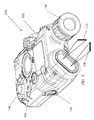
- FIG. 3 is an isometric view of an optical bench assembly consistent with an exemplary embodiment.
- FIG. 4 is an exploded isometric view of the optical bench assembly of FIG. 3 .
- FIG. 5 is a cross-sectional view of the optical bench assembly of FIG. 3 .
- FIG. 6 is an exploded isometric view of a lens/housing assembly consistent with an exemplary embodiment.
- FIG. 7 is an exploded isometric view of a diode mounting assembly consistent with an exemplary embodiment.
- FIG. 8 is a front view of a laser diode consistent with an exemplary embodiment.
- FIG. 9 is a graph of quantum efficiency vs. wavelength for a variety of imaging systems.
- FIG. 10 is a block diagram of a SWIR vision system consistent with an embodiment of the invention.
- FIG. 11A is a block diagram of a SWIR beacon consistent with a first embodiment of the invention.
- FIG. 11B is a block diagram of a SWIR beacon consistent with a second embodiment of the invention.
- FIG. 1 is an isometric view of a weapon mountable sight 100 consistent an exemplary embodiment
- FIG. 2 is a side view of the weapon mountable sight 100 attached to a weapon 200 consistent an exemplary embodiment.
- the sight 100 may generate a first generally rectangular light beam 108 and a second generally rectangular light beam 110 for projection of a cross 120 having a first bar 122 having a length L 1 and a width W 1 , the length L 1 being substantially greater (5 ⁇ or more) than the width W 1 and a second bar 124 having a length L 2 and a width W 2 , the length L 2 being substantially greater than the width W 2 on a target 130 .
- Some defocusing of the projected cross 120 may occur, but the resulting shape on a target generally conforms to a rectangle.
- the sight 100 may also have an infrared illuminator 194 that can be manipulated to go from a narrow beam of light to a wide, generally circular, beam of light.
- the sight 100 may have a housing 102 for providing protection to internal components from unintended contact or debris.
- the sight 100 may be removably coupleable to the weapon 200 such as the M4A1 carbine or other weapon with a suitable attachment method, for example a rail grabber, slide-lock® mechanism, or other clamp.
- a sight may be incorporated in and/or formed as part of a weapon.
- the housing 102 may have a first adjustor 104 and a second adjustor 106 to allow an operator to boresight the cross 120 with a projectile point of impact on a target 130 at a known distance or with a boresight alignment tool, for example a barrel mounted boresight laser.
- FIG. 3 is an isometric view of an optical bench assembly 150 consistent with an exemplary embodiment
- FIG. 4 is an exploded isometric view of the optical bench assembly 150
- FIG. 5 is a cross-sectional view of the optical bench assembly 150
- FIG. 6 is an exploded isometric view of a lens/housing assembly consistent with an exemplary embodiment
- FIG. 7 is an exploded isometric view of a diode mounting assembly consistent with an exemplary embodiment
- FIG. 8 is a front view of a laser diode consistent with an exemplary embodiment.
- An optical bench assembly 150 may have an optical bench 152 having a pivot adjuster section 152 A, a dual barrel section 152 B, and a flexure section 152 C.
- the sections may be coupled together using one or more mechanical fasteners 190 or an epoxy.
- the optical bench sections 152 A, 152 B, and 152 C may be a unitary piece or made of two or more pieces.
- An optical bench 152 may provide a structure to support electrical and optical components that may be secured to the optical bench 152 during the assembly process.
- the optical bench 152 can be made of metal, plastic, or other suitable material.
- the flexure section 152 C may have a groove 112 or other feature that allows the optical bench 152 to be coupled to the housing 102 .
- the adjustors 104 , 106 may contact the pivot adjuster section 152 A to steer the first light beam 108 and the second light beam 110 relative to the housing 102 to allow the first beam 108 and second beam 110 to be boresighted to a weapon.
- the adjustors 104 , 106 may be orthogonally offset 90 degrees from each other to provide elevation and windage adjustment of the light beams 108 , 110 relative to the housing 102 .
- Springs or other biasing mechanisms may be used to provide a counter force to the adjustors 104 , 106 .
- electrically controllable actuators for example MEMS or piezoelectric actuators, may be used to steer the light beams 108 , 110 .
- the optical bench 152 may be configured to support a first pivot flange 180 A, a second pivot flange 180 B, a first laser aim assembly 158 A, and a second laser aim assembly 158 B.
- the optical bench assembly 150 can incorporate two or more laser diodes 154 A, 154 B.
- the laser diodes have a principal wavelength in the near infrared spectrum (between 750 nm and 3000 nm).
- the laser diodes 154 A, 154 B operate around 1550 nm.
- the first light beam 108 may be generated by the first laser diode 154 A having a first emitter 126 (see FIG. 8 ) having a length L E and a width W E , the emitter length L E being substantially greater than (5 ⁇ or more) the width W E and a second laser diode 154 B having a second emitter having a length L E and a width W E , the emitter length L E being substantially greater than the width W E .
- the laser emitter 126 may have a width W E of 1-5 ⁇ m and a length of 50-300 ⁇ m. Other sized lasers may be used without departing from the invention.
- the laser diodes 154 A, 154 B may be powered by an internal battery or external power supply and operated at different user selectable power levels through an actuator 196 .
- the first laser aim assembly 158 A may have a first diode mount assembly 162 A secured to a first lens/housing assembly 160 A.
- the first diode mount assembly 162 A may have a first laser diode 154 A secured by a first laser pivot mount 168 A and a first laser mount 164 A, with or without an epoxy.
- the epoxy may be time, wavelength, or thermally sensitive to allow proper positioning prior to forming a permanent bond.
- the first laser pivot mount 168 A may have an arcuate surface 166 .
- the first lens/housing assembly 160 A may have a first collimating lens 172 A secured between a first lens retainer 174 A and a first lens mount 170 A, with or with an epoxy.
- the first lens/housing assembly 160 A may have a threaded portion that cooperates with a threaded portion on the first diode mount assembly 162 A to allow an assembler to collimate the light beam from the emitter by increasing or decreasing the distance between the emitter 126 and the collimating lens 172 A.
- the first lens/housing laser assembly 160 A may then be secured to the first diode mount assembly 162 A.
- the first lens/housing laser assembly 160 A and the first diode mount assembly 162 A may slide relative to each other to allow for precise positioning of the first collimating lens 172 A relative to the emitter 126 .
- the pivot flange 180 A may be coupled to the optical bench section 152 B.
- the pivot flange 180 A may have an arcuate rear surface 190 that cooperates with arcuate surface 166 of the first laser pivot mount 168 A to allow an assembler to steer the first laser assembly 158 A relative to the pivot flange 180 A to allow the light beams 108 , 110 to be steered.
- a second laser aim assembly 158 B may have a second diode mounting assembly 162 B secured to a lens/housing assembly 160 B.
- the second diode mount assembly 162 B may have a second laser diode 154 B secured by a second laser pivot mount 168 B and a second laser mount 164 B, with or without epoxy.
- the second lens/housing assembly 160 B may have a second collimating lens 172 B secured between a second lens retainer 174 B and a second lens mount 170 B, with or with an epoxy.
- the first laser aim assembly 158 A may be positioned in the optical bench 152 such that a longitudinal axis of the emitter 126 of the first laser diode 154 A is generally perpendicular to a longitudinal axis of the emitter 126 of the second laser diode 154 B.
- the generally rectangular first light beam 108 generated by the emitter 126 in the first laser diode 154 A may be oriented generally perpendicular to the generally rectangular second light beam 110 generated by the emitter 126 in the second laser diode 154 B.
- the first light beam 108 and the second light beam 110 may be aligned such that a midpoint of the first bar 122 of the cross 120 on the target 130 is aligned approximately with a midpoint of the second bar 124 on the target 130 when the target 130 is at a known distance from the aiming device 100 .
- FIG. 9 is a graph of quantum efficiency vs. wavelength for a variety of imaging systems.
- the graph shows the visible spectrum extending from approximately 450 nm to approximately 750 nm and the short wave infrared spectrum extending from approximately 750 nm to approximately 3000 nm.
- the graph shows generation III image intensification night vision devices (NVG Gen III) operating from approximately 600 nm to just below 1 ⁇ m.
- NVG Gen III generation III image intensification night vision devices
- Infrared laser illuminators and pointers operating around 830 nm can therefore be seen by these devices.
- these illuminators and pointers can also be seen by the enemy.
- Si CCD sensors also work in these wavelengths and can be used by the enemy to detect near IR (NIR) pointers and illuminators.
- NIR near IR
- FIG. 9 also shows several InGaAs sensors (1.7 ⁇ m, 2.2 ⁇ m, and 2.5 ⁇ m). The graph also shows that lasers operating at 1.06 ⁇ m and 1.55 ⁇ m are visible by these sensors, but not by the NVG or Si CCD sensors.
- FIG. 10 a block diagram of a SWIR vision system 100 consistent with an embodiment of the invention.
- the system electronics and optics are housed in a housing 1002 , which can be mounted to a rifle or a military helmet and are powered by batteries 1004 .
- Information from a short wave infrared (SWIR) detector channel 1006 is directed towards one or mores eyepieces 1010 for viewing by an operator.
- a channel may be an optical path through which scene information may travel and include a sensor.
- the eyepieces 1010 may have one or more ocular lenses for magnifying and/or focusing the image.
- the SWIR channel 1006 may be configured to process information in a range of wavelengths from 750 nm to 3000 nm.
- the SWIR channel 106 may have an objective focus 112 and an SWIR detector 1014 .
- the low end and the high end of the first range of wavelengths may vary without departing from the invention.
- the housing 1002 may have actuators to control system on/off and display brightness and auto/manual gain of the SWIR channel.
- An on/off brightness potentiometer 1020 allows the operator to turn the system on and off and control the brightness of the image in the displays 1046 and the auto/manual gain potentiometer 1024 allows the operator to select between manual and automatic control of the gain of the SWIR channel 1006 .
- the SWIR vision system 1000 light entering the SWIR detector is sensed by a two-dimensional array of SWIR detector elements. The detector elements sense the reflected light and create a very detailed pattern, which is then translated into electric impulses that are communicated to the signal-processing electronics 1040 . The signal-processing electronics then outputs the information to one or more displays 1046 for viewing by an operator.
- the display(s) 1046 may be a miniature flat panel display, for example a monochrome organic light emitting diode (OLED) microdisplay or a liquid crystal display (LCD).
- OLED organic light emitting diode
- the SWIR vision system 1000 may include infrared illuminator electronics 1050 .
- the illuminator 1050 may be adjustable from a narrow pointer to a wide flood. Alternatively, the illuminator 1050 may have a fixed divergence.
- the illuminator 1050 may operate in the shortwave infrared spectrum, for example 1 ⁇ m to 3 ⁇ m, for example at 1060 nm or 1550 nm.
- a user of this system 1000 can view an area of interest or point at an area of interest without being detected by traditional image intensification night vision devices that operate at lower wavelengths.
- FIG. 11A is a block diagram of a SWIR beacon 300 and FIG. 11B is a block diagram of a SWIR beacon 300 ′.
- the beacons may be covertly used to mark landing zones for helicopters, designate a friendly soldier, or to mark a target of interest. An operator using a night vision device with a SWIR detector would be able to see the beacon, but an operator using his naked eye or with an image intensification night vision device would not be able to see the beacon.
- the beacons 300 , 300 ′ may be coupled to a power supply 302 , for example a conventional 9v battery having terminals 304 and 306 . Other power sources may be used without departing from the invention.
- the beacons 300 , 300 ′ may be configured to output light in the SWIR range, for example at a wavelength above that which can be seen with image intensification night vision equipment, for example greater than 900 nm.
- Beacon 300 may have a first housing 320 having terminals 322 and 324 that cooperate with battery terminals 304 , 306 and an opening 328 ′ through which a laser diode 328 extends.
- the laser diode 328 may be coupled to terminal 324 through a pulse generator.
- the laser diode 328 may operate at a frequency above that which can be seen with image intensification night vision equipment, for example greater than 900 nm, for example 1060 nm or 1150 nm.
- the frequency of the pulse generator may be adjustable.
- the operator placing the beacon may set the beacon to a particular frequency to distinguish one beacon from another.
- the operator can set the beacon to a particular frequency so that if the operator sees a beacon at an improper frequency, for example a beacon found by the enemy, the operator can ignore that beacon.
- the frequency may be set using an encoder 340 extending from the housing 320 .
- the frequency may be set through a process in which the operator connects the beacon 300 to the power supply 302 and then disconnects it.
- a processor 342 in the beacon could be used to set the frequency based on time between connects and disconnects, the number of disconnects in a preset amount of time, or the frequency of the disconnects.
- the beacon may have a port 344 through which the frequency is set.
- the beacon could receive a wireless signal to set the frequency.
- Beacon 300 ′ may have a first housing 330 having terminals 322 and 324 that cooperate with battery terminals 304 , 306 and an opening 338 ′ in which a long pass filter window or lens 350 is located.
- a light source 338 for example an incandescent bulb or LED, may be located in proximity to the window or lens 350 to allow light having a frequency above that which can be seen with image intensification night vision equipment, for example greater than 900 nm, to shine therethrough.
- the light source 338 may be coupled to terminal 324 through a pulse generator 360 .
- the frequency of the pulse generator may be adjustable. The frequency of the pulses may be set as noted above with relation to beacon 300 .
- a housing for at least partially enclosing a first laser diode and a second laser diode with each diode having an emitter having a length and a width with the length being substantially greater than the width and an optical bench configured to hold the first and the second laser diodes to project a cross on a target.
- the resulting cross made up of a first generally rectangular shape having a length and a width, the length being substantially greater than the width and a second generally rectangular shape having a length and a width, the length being substantially greater than the width.
- a night vision system including a housing, a first channel at least partially disposed within the housing for processing information in a first range of wavelengths and a laser having a principal wavelength that is above 900 nm and visible through the night vision system.
- a night vision system including a housing, a first channel for processing information in a first range of wavelengths, a display coupled to the first channel, and an infrared laser operating at a wavelength above 900 nm.
Landscapes
- Physics & Mathematics (AREA)
- Optics & Photonics (AREA)
- General Physics & Mathematics (AREA)
- Astronomy & Astrophysics (AREA)
- Engineering & Computer Science (AREA)
- General Engineering & Computer Science (AREA)
- Studio Devices (AREA)
Abstract
Description
Claims (7)
Priority Applications (1)
| Application Number | Priority Date | Filing Date | Title |
|---|---|---|---|
| US12/015,736 US7784192B2 (en) | 2007-01-18 | 2008-01-17 | SWIR vision and illumination devices |
Applications Claiming Priority (4)
| Application Number | Priority Date | Filing Date | Title |
|---|---|---|---|
| US88545407P | 2007-01-18 | 2007-01-18 | |
| US90978607P | 2007-04-03 | 2007-04-03 | |
| US93937707P | 2007-05-22 | 2007-05-22 | |
| US12/015,736 US7784192B2 (en) | 2007-01-18 | 2008-01-17 | SWIR vision and illumination devices |
Publications (2)
| Publication Number | Publication Date |
|---|---|
| US20090224154A1 US20090224154A1 (en) | 2009-09-10 |
| US7784192B2 true US7784192B2 (en) | 2010-08-31 |
Family
ID=41052641
Family Applications (1)
| Application Number | Title | Priority Date | Filing Date |
|---|---|---|---|
| US12/015,736 Active 2028-06-26 US7784192B2 (en) | 2007-01-18 | 2008-01-17 | SWIR vision and illumination devices |
Country Status (1)
| Country | Link |
|---|---|
| US (1) | US7784192B2 (en) |
Cited By (14)
| Publication number | Priority date | Publication date | Assignee | Title |
|---|---|---|---|---|
| US20120110887A1 (en) * | 2010-11-10 | 2012-05-10 | Raytheon Company | Method and System for Attenuating A Wavelength Shifting Source |
| WO2013003748A1 (en) * | 2011-06-29 | 2013-01-03 | Vision Systems International, Llc | System for locating a position of an object |
| US20130182739A1 (en) * | 2012-01-17 | 2013-07-18 | Quarton, Inc. | Twin-Beam Laser Module For Use With A Laser Sight |
| US8826583B2 (en) * | 2012-06-27 | 2014-09-09 | Trackingpoint, Inc. | System for automatically aligning a rifle scope to a rifle |
| US20150247703A1 (en) * | 2012-10-22 | 2015-09-03 | Wilcox Industries Corp. | Combined Laser Range Finder and Sighting Apparatus Having Dual Function Laser and Method |
| US9574759B2 (en) * | 2015-01-16 | 2017-02-21 | Steiner Eoptics, Inc. | Adjustable laser illumination pattern |
| US10175030B2 (en) * | 2017-03-13 | 2019-01-08 | Sensors Unlimited, Inc. | Threat detection |
| US10386160B2 (en) | 2015-05-01 | 2019-08-20 | B.E. Meyers & Co., Inc. | Modular illumination and aiming apparatus |
| US20210199769A1 (en) * | 2018-05-23 | 2021-07-01 | Iris Industries Sa | Short wavelength infrared lidar |
| US11391904B2 (en) | 2019-11-21 | 2022-07-19 | Eotech, Llc | Temperature stabilized holographic sight |
| US20220228839A1 (en) * | 2021-01-18 | 2022-07-21 | Trajectory, LLC | Aiming apparatus for a firearm |
| US11435162B2 (en) | 2019-11-21 | 2022-09-06 | Eotech, Llc | Modular weapon sight assembly |
| US11449003B2 (en) | 2019-11-21 | 2022-09-20 | Eotech, Llc | Position adjustment in holographic sight |
| US11467391B2 (en) | 2019-11-21 | 2022-10-11 | Eotech, Llc | Unitary carrier for holographic components |
Families Citing this family (12)
| Publication number | Priority date | Publication date | Assignee | Title |
|---|---|---|---|---|
| US7744595B2 (en) * | 2000-08-01 | 2010-06-29 | Arqos Surgical, Inc. | Voltage threshold ablation apparatus |
| US20120140201A1 (en) * | 2007-03-27 | 2012-06-07 | Grauslys Richard P | Rangefinder with integrated red-dot sight |
| CA2706979C (en) * | 2007-11-27 | 2016-02-09 | The Flewelling Ford Family Trust | Identification system and method using highly collimated source of electromagnetic radiation |
| US8119987B2 (en) * | 2008-06-27 | 2012-02-21 | Yoon Howard W | Process and apparatus for the measurement of thermal radiation using regular glass optics and short-wave infrared detectors |
| US9305963B2 (en) * | 2011-04-08 | 2016-04-05 | Lasermax, Inc. | Marking system and method |
| US8735817B2 (en) * | 2011-06-09 | 2014-05-27 | Exelis, Inc. | Clip-on target designation sensor to night vision goggles |
| WO2013088386A1 (en) * | 2011-12-14 | 2013-06-20 | Aselsan Elektronik Sanayi Ve Ticaret Anonim Sirketi | A night vision sighting device |
| US10060702B2 (en) | 2013-03-15 | 2018-08-28 | Leupold & Stevens, Inc. | Dual field optical aiming system for projectile weapons |
| US9115958B2 (en) | 2013-03-15 | 2015-08-25 | Leupold & Stevens, Inc. | Dual field optical aiming system for projectile weapons |
| GB2547344B (en) | 2014-10-13 | 2021-06-09 | Wilcox Ind Corp | Combined reflex and laser sight with elevation macro-adjustment mechanism |
| USD810854S1 (en) * | 2015-05-23 | 2018-02-20 | Leupold & Stevens, Inc. | Sighting device |
| US10432840B2 (en) * | 2015-10-08 | 2019-10-01 | L-3 Communication-Insight Technology Division | Fusion night vision system |
Citations (17)
| Publication number | Priority date | Publication date | Assignee | Title |
|---|---|---|---|---|
| US3867764A (en) * | 1973-04-24 | 1975-02-25 | Us Army | Aiming light and aiming light adapter for use on a weapon |
| US5272514A (en) * | 1991-12-06 | 1993-12-21 | Litton Systems, Inc. | Modular day/night weapon aiming system |
| US5502455A (en) * | 1994-07-21 | 1996-03-26 | Honeywell Inc. | Method and appartus for producing a symbology display into a night vision system |
| US5539990A (en) * | 1995-05-30 | 1996-07-30 | Le; Mike | Three-dimensional optical levelling, plumbing and angle-calibrating instrument |
| US6460447B1 (en) * | 1999-02-09 | 2002-10-08 | Brad E. Meyers | Weapon aiming |
| US20040060222A1 (en) * | 2002-09-26 | 2004-04-01 | David Oz | Accessory mount for a firearm |
| US20040093749A1 (en) * | 2002-11-19 | 2004-05-20 | Shuming Wu | Auxiliary handle with a laser alignment device for drills |
| US6819495B2 (en) * | 2002-06-17 | 2004-11-16 | International Technologies (Lasers) Ltd. | Auxiliary optical unit attachable to optical devices, particularly telescopic gun sights |
| US6892488B1 (en) * | 2003-11-04 | 2005-05-17 | Robert P Serravalle | Illuminating recoil guide rod |
| US6941665B1 (en) * | 2004-03-17 | 2005-09-13 | Awi Acquisition Company, Inc. | Pivotable laser level |
| US6964106B2 (en) * | 2004-02-11 | 2005-11-15 | Black & Decker Inc. | Laser level |
| US20070056174A1 (en) * | 2004-03-18 | 2007-03-15 | Black & Decker Inc. | Laser level |
| US7204027B2 (en) * | 2005-02-15 | 2007-04-17 | Robotoolz, Ltd. | Method and apparatus for determining reference levels and flatness of a surface |
| US20070271800A1 (en) * | 2006-05-26 | 2007-11-29 | William Hersey | Laser-based alignment tool |
| US20080060248A1 (en) * | 2006-09-08 | 2008-03-13 | Jerrold Scott Pine | Stealth Laser Sighting System For Firearms |
| US20080276473A1 (en) * | 2007-05-07 | 2008-11-13 | Michael Raschella | Method of projecting zero-convergence aiming beam on a target and zero-convergence laser aiming system |
| US7493722B2 (en) * | 2005-11-17 | 2009-02-24 | Insight Technology Incorporated | Tactical illuminator |
-
2008
- 2008-01-17 US US12/015,736 patent/US7784192B2/en active Active
Patent Citations (17)
| Publication number | Priority date | Publication date | Assignee | Title |
|---|---|---|---|---|
| US3867764A (en) * | 1973-04-24 | 1975-02-25 | Us Army | Aiming light and aiming light adapter for use on a weapon |
| US5272514A (en) * | 1991-12-06 | 1993-12-21 | Litton Systems, Inc. | Modular day/night weapon aiming system |
| US5502455A (en) * | 1994-07-21 | 1996-03-26 | Honeywell Inc. | Method and appartus for producing a symbology display into a night vision system |
| US5539990A (en) * | 1995-05-30 | 1996-07-30 | Le; Mike | Three-dimensional optical levelling, plumbing and angle-calibrating instrument |
| US6460447B1 (en) * | 1999-02-09 | 2002-10-08 | Brad E. Meyers | Weapon aiming |
| US6819495B2 (en) * | 2002-06-17 | 2004-11-16 | International Technologies (Lasers) Ltd. | Auxiliary optical unit attachable to optical devices, particularly telescopic gun sights |
| US20040060222A1 (en) * | 2002-09-26 | 2004-04-01 | David Oz | Accessory mount for a firearm |
| US20040093749A1 (en) * | 2002-11-19 | 2004-05-20 | Shuming Wu | Auxiliary handle with a laser alignment device for drills |
| US6892488B1 (en) * | 2003-11-04 | 2005-05-17 | Robert P Serravalle | Illuminating recoil guide rod |
| US6964106B2 (en) * | 2004-02-11 | 2005-11-15 | Black & Decker Inc. | Laser level |
| US6941665B1 (en) * | 2004-03-17 | 2005-09-13 | Awi Acquisition Company, Inc. | Pivotable laser level |
| US20070056174A1 (en) * | 2004-03-18 | 2007-03-15 | Black & Decker Inc. | Laser level |
| US7204027B2 (en) * | 2005-02-15 | 2007-04-17 | Robotoolz, Ltd. | Method and apparatus for determining reference levels and flatness of a surface |
| US7493722B2 (en) * | 2005-11-17 | 2009-02-24 | Insight Technology Incorporated | Tactical illuminator |
| US20070271800A1 (en) * | 2006-05-26 | 2007-11-29 | William Hersey | Laser-based alignment tool |
| US20080060248A1 (en) * | 2006-09-08 | 2008-03-13 | Jerrold Scott Pine | Stealth Laser Sighting System For Firearms |
| US20080276473A1 (en) * | 2007-05-07 | 2008-11-13 | Michael Raschella | Method of projecting zero-convergence aiming beam on a target and zero-convergence laser aiming system |
Cited By (22)
| Publication number | Priority date | Publication date | Assignee | Title |
|---|---|---|---|---|
| US8621759B2 (en) * | 2010-11-10 | 2014-01-07 | Raytheon Canada Limited | Method and system for attenuating a wavelength shifting source |
| US20120110887A1 (en) * | 2010-11-10 | 2012-05-10 | Raytheon Company | Method and System for Attenuating A Wavelength Shifting Source |
| WO2013003748A1 (en) * | 2011-06-29 | 2013-01-03 | Vision Systems International, Llc | System for locating a position of an object |
| US20130182739A1 (en) * | 2012-01-17 | 2013-07-18 | Quarton, Inc. | Twin-Beam Laser Module For Use With A Laser Sight |
| US8898915B2 (en) * | 2012-01-17 | 2014-12-02 | Quarton, Inc | Twin-beam laser module for use with a laser sight |
| US9372051B2 (en) | 2012-06-27 | 2016-06-21 | Trackingpoint, Inc. | System for automatically aligning a rifle scope to a rifle |
| US8826583B2 (en) * | 2012-06-27 | 2014-09-09 | Trackingpoint, Inc. | System for automatically aligning a rifle scope to a rifle |
| US20150247703A1 (en) * | 2012-10-22 | 2015-09-03 | Wilcox Industries Corp. | Combined Laser Range Finder and Sighting Apparatus Having Dual Function Laser and Method |
| US10012474B2 (en) * | 2012-10-22 | 2018-07-03 | Wilcox Industries Corp. | Combined laser range finder and sighting apparatus having dual function laser and method |
| US9574759B2 (en) * | 2015-01-16 | 2017-02-21 | Steiner Eoptics, Inc. | Adjustable laser illumination pattern |
| US11105590B2 (en) | 2015-05-01 | 2021-08-31 | B.E. Meyers & Co., Inc. | Modular illumination and aiming apparatus |
| US10386160B2 (en) | 2015-05-01 | 2019-08-20 | B.E. Meyers & Co., Inc. | Modular illumination and aiming apparatus |
| US10782100B2 (en) | 2015-05-01 | 2020-09-22 | B.E. Meyers & Co., Inc. | Modular illumination and aiming apparatus |
| US11629935B2 (en) | 2015-05-01 | 2023-04-18 | B.E. Meyers & Co., Inc. | Modular illumination and aiming apparatus |
| US10175030B2 (en) * | 2017-03-13 | 2019-01-08 | Sensors Unlimited, Inc. | Threat detection |
| US20210199769A1 (en) * | 2018-05-23 | 2021-07-01 | Iris Industries Sa | Short wavelength infrared lidar |
| US11391904B2 (en) | 2019-11-21 | 2022-07-19 | Eotech, Llc | Temperature stabilized holographic sight |
| US11435162B2 (en) | 2019-11-21 | 2022-09-06 | Eotech, Llc | Modular weapon sight assembly |
| US11449003B2 (en) | 2019-11-21 | 2022-09-20 | Eotech, Llc | Position adjustment in holographic sight |
| US11467391B2 (en) | 2019-11-21 | 2022-10-11 | Eotech, Llc | Unitary carrier for holographic components |
| US20220228839A1 (en) * | 2021-01-18 | 2022-07-21 | Trajectory, LLC | Aiming apparatus for a firearm |
| US11808546B2 (en) * | 2021-01-18 | 2023-11-07 | Trajectory, LLC | Aiming apparatus for a firearm |
Also Published As
| Publication number | Publication date |
|---|---|
| US20090224154A1 (en) | 2009-09-10 |
Similar Documents
| Publication | Publication Date | Title |
|---|---|---|
| US7784192B2 (en) | SWIR vision and illumination devices | |
| US7325318B2 (en) | Compact multifunction sight | |
| KR102652020B1 (en) | Observation optical device with integrated display system | |
| US10942005B2 (en) | Combined reflex and laser sight with co-aligned iron sights | |
| EP0545527B1 (en) | Weapon aiming system | |
| US4266873A (en) | Collinear aiming light image viewer | |
| KR101972099B1 (en) | Viewer with display overlay | |
| US9316460B2 (en) | One hand operational combo sight device | |
| AU2013248208B2 (en) | Combined laser range finder and sighting apparatus having dual function laser and method | |
| US8256152B2 (en) | Method and apparatus for collimating and coaligning optical components | |
| US9069172B1 (en) | Multi-mode sight | |
| KR20210013046A (en) | Field of view optics with direct active reticle targeting | |
| US20230228531A1 (en) | Modular illumination and aiming apparatus | |
| US20070009860A1 (en) | Boresight device and method | |
| US20120140201A1 (en) | Rangefinder with integrated red-dot sight | |
| US9389046B2 (en) | Sight module for firearm | |
| JP7393951B2 (en) | Sighting scope with illuminated sight and thermal imaging camera | |
| US20070236790A1 (en) | Night vision attachment mountable on a firearm and intended for a sighting telescope | |
| JPS60182406A (en) | Sight device | |
| US9426389B1 (en) | Second imaging device adaptable for use with first imaging device and method for using same | |
| WO2005045349A1 (en) | Target designator | |
| US20200404194A1 (en) | Reflex sight incorporating an infrared camera |
Legal Events
| Date | Code | Title | Description |
|---|---|---|---|
| AS | Assignment |
Owner name: INSIGHT TECHNOLOGY INCORPORATED, NEW HAMPSHIRE Free format text: ASSIGNMENT OF ASSIGNORS INTEREST;ASSIGNORS:JANCIC, DALE A.;GRAUSLYS, RICHARD P.;HOHENBERGER, ROGER T.;REEL/FRAME:020603/0375;SIGNING DATES FROM 20080303 TO 20080304 Owner name: INSIGHT TECHNOLOGY INCORPORATED, NEW HAMPSHIRE Free format text: ASSIGNMENT OF ASSIGNORS INTEREST;ASSIGNORS:JANCIC, DALE A.;GRAUSLYS, RICHARD P.;HOHENBERGER, ROGER T.;SIGNING DATES FROM 20080303 TO 20080304;REEL/FRAME:020603/0375 |
|
| AS | Assignment |
Owner name: L-3 INSIGHT TECHNOLOGY INCORPORATED, NEW HAMPSHIRE Free format text: CHANGE OF NAME;ASSIGNOR:INSIGHT TECHNOLOGY INCORPORATED;REEL/FRAME:024787/0251 Effective date: 20100415 |
|
| STCF | Information on status: patent grant |
Free format text: PATENTED CASE |
|
| AS | Assignment |
Owner name: L-3 COMMUNICATIONS INSIGHT TECHNOLOGY INCORPORATED Free format text: ASSIGNMENT OF ASSIGNORS INTEREST;ASSIGNOR:L-3 INSIGHT TECHNOLOGY INCORPORATED;REEL/FRAME:027052/0397 Effective date: 20110929 |
|
| FPAY | Fee payment |
Year of fee payment: 4 |
|
| MAFP | Maintenance fee payment |
Free format text: PAYMENT OF MAINTENANCE FEE, 8TH YEAR, LARGE ENTITY (ORIGINAL EVENT CODE: M1552) Year of fee payment: 8 |
|
| MAFP | Maintenance fee payment |
Free format text: PAYMENT OF MAINTENANCE FEE, 12TH YEAR, LARGE ENTITY (ORIGINAL EVENT CODE: M1553); ENTITY STATUS OF PATENT OWNER: LARGE ENTITY Year of fee payment: 12 |