US7787477B2 - Address-transparent device and method - Google Patents
Address-transparent device and method Download PDFInfo
- Publication number
- US7787477B2 US7787477B2 US11/178,626 US17862605A US7787477B2 US 7787477 B2 US7787477 B2 US 7787477B2 US 17862605 A US17862605 A US 17862605A US 7787477 B2 US7787477 B2 US 7787477B2
- Authority
- US
- United States
- Prior art keywords
- address
- packet
- transparent device
- destination
- port
- Prior art date
- Legal status (The legal status is an assumption and is not a legal conclusion. Google has not performed a legal analysis and makes no representation as to the accuracy of the status listed.)
- Active, expires
Links
Images


Classifications
-
- H—ELECTRICITY
- H01—ELECTRIC ELEMENTS
- H01L—SEMICONDUCTOR DEVICES NOT COVERED BY CLASS H10
- H01L21/00—Processes or apparatus adapted for the manufacture or treatment of semiconductor or solid state devices or of parts thereof
-
- H—ELECTRICITY
- H04—ELECTRIC COMMUNICATION TECHNIQUE
- H04L—TRANSMISSION OF DIGITAL INFORMATION, e.g. TELEGRAPHIC COMMUNICATION
- H04L45/00—Routing or path finding of packets in data switching networks
-
- H—ELECTRICITY
- H04—ELECTRIC COMMUNICATION TECHNIQUE
- H04L—TRANSMISSION OF DIGITAL INFORMATION, e.g. TELEGRAPHIC COMMUNICATION
- H04L45/00—Routing or path finding of packets in data switching networks
- H04L45/54—Organization of routing tables
-
- H—ELECTRICITY
- H04—ELECTRIC COMMUNICATION TECHNIQUE
- H04L—TRANSMISSION OF DIGITAL INFORMATION, e.g. TELEGRAPHIC COMMUNICATION
- H04L61/00—Network arrangements, protocols or services for addressing or naming
- H04L61/09—Mapping addresses
- H04L61/25—Mapping addresses of the same type
- H04L61/2503—Translation of Internet protocol [IP] addresses
-
- H—ELECTRICITY
- H04—ELECTRIC COMMUNICATION TECHNIQUE
- H04L—TRANSMISSION OF DIGITAL INFORMATION, e.g. TELEGRAPHIC COMMUNICATION
- H04L61/00—Network arrangements, protocols or services for addressing or naming
- H04L61/09—Mapping addresses
- H04L61/10—Mapping addresses of different types
- H04L61/103—Mapping addresses of different types across network layers, e.g. resolution of network layer into physical layer addresses or address resolution protocol [ARP]
-
- H—ELECTRICITY
- H04—ELECTRIC COMMUNICATION TECHNIQUE
- H04L—TRANSMISSION OF DIGITAL INFORMATION, e.g. TELEGRAPHIC COMMUNICATION
- H04L67/00—Network arrangements or protocols for supporting network services or applications
- H04L67/01—Protocols
- H04L67/12—Protocols specially adapted for proprietary or special-purpose networking environments, e.g. medical networks, sensor networks, networks in vehicles or remote metering networks
Definitions
- the present invention relates generally to managing operations in semiconductor manufacturing, and more particularly to providing a cost-effective solution in adding services in a semiconductor fab.
- Key components used by a fab in semiconductor manufacturing include tools (e.g., deposition chambers, reactors), sensors that monitor the tools (e.g., FTIR sensors, mass spectrographs, thermocouples) and hosts or distributed processors that store and analyze data from the sensors regarding tool operation.
- tools e.g., deposition chambers, reactors
- sensors e.g., FTIR sensors, mass spectrographs, thermocouples
- hosts or distributed processors that store and analyze data from the sensors regarding tool operation.
- FIG. 1 A conventional semiconductor fab 100 with sample IP addresses is shown in FIG. 1 for communicating messages between hosts and a tool.
- a first host 110 with an IP address of 10.10.10.5 is connected to a tool 130 with an IP address of 10.10.10.7 through a switch 150 and a switch 170 on a network 140 .
- a second host 120 with an IP address of 10.10.10.6 is connected to the tool 130 through a switch 160 and the switch 170 on the network 140 .
- the first host 110 attempts to access the tool 130
- the first host 110 is configured to access the tool 130 at a specific port, e.g. port 5000.
- a prior application described a transparent method of listening to data from the sensors and providing it to the hosts or distributed processors using high speed and error-resistant technologies such as TCP/IP over Ethernet.
- the prior application was by inventors Uzi Lev-Ami and Yossef Ilan Reich, “Method and Apparatus for Monitoring Host to Tool Communications,” application Ser. No. 09/935,213, filed on 22 Aug. 2001, which is incorporated by reference.
- the prior application describes a listening post that could eavesdrop on serial communications from a tool or sensor using an optically isolated connector. Using the eavesdropping approach, one could prove that the fab communications and data collection infrastructure could be upgraded without requiring modification of tools or sensors, at a low risk. The upgrade feasibility could be demonstrated without dismantling the incumbent communications infrastructure.
- the present invention describes an address-transparent device that couples between two network interfaces in a semiconductor fab for communicating packets between a host coupled to a first network interface and a tool coupled to a second network interface.
- the address-transparent device couples between two networks in a semiconductor fab for communicating packets between a host on a first network and a tool on a second network.
- the address-transparent device routes packets between the first network and the second network that is independent of any protocol.
- the address-transparent device couples to the host through the first network and couples to the tool through the second network where the address-transparent device having a first port with no IP address, and a second port with either no IP address or a predefined IP address.
- the address-transparent device intercepts packets for local use by a data consumer that resides within or outside of the address-transparent device.
- the address-transparent device can intercept all or a portion of data streams, while forwards other portions of data streams to a destination.
- the header of the original packet is stored for subsequent use for sending a reply to an intercepted packet.
- the address-transparent device reroutes packet to another destination by changing the header of the received packet.
- the header of the original packet is modified, replacing the original header information with the header information of the destination device.
- the header of the original packet is stored for subsequent use for sending a reply to a rerouted packet.
- the present invention also provides a failsafe switch that is activated when the address-transparent device becomes defective or the software inside the address-transparent device fails to function properly.
- a system comprises a first network interface; a second network interface; and an address-transparent device coupled between the first and second network interfaces and adapted to receive at least one packet, the address-transparent device having a first port coupled to the first network and a second port coupled to the second network, the first port in the address-transparent device having no IP address.
- the present invention provides a cost-effective solution to add services in a manufacturing environment without significant delays and fees associated in obtain a new IP address for the newly inserted device.
- the address-transparent device functions like a plug-and-play box that couples readily between a host, a tool and a sensor while providing a means to forward, intercept and route packets between devices couples to the first and second networks.
- FIG. 1 is a simplified block diagram illustrating a conventional semiconductor fab for communication between hosts and a tool.
- FIG. 2 is a block diagram illustrating an environment in which aspects of the present invention are particularly useful.
- FIG. 3 is a simplified block diagram illustrating an address-transparent device deployed in a semiconductor fab in accordance with the present invention.
- FIG. 4 is a simplified block diagram illustrating one embodiment of a failsafe switch coupled to the address-transparent device in accordance with the present invention.
- FIG. 5 is a simplified block diagram illustrating the filtering of packets by the address-transparent device in accordance with the present invention.
- FIG. 6 is a simplified block diagram illustrating an exemplary format of a packet header for appending to a data packet in accordance with the present invention.
- FIGS. 7A-7D are simplified block diagrams illustrating packet header examples in rerouting a packet in accordance with the present invention.
- FIG. 8 is a simplified flow chart illustrating the filtering process in which the address-transparent device performs in analyzing packets in accordance with the present invention.
- FIG. 9 is a simplified block diagram illustrating one embodiment in the implementation of the address-transparent device and the failsafe switch in accordance with the present invention.
- SECS message protocols communication infrastructure and hosting modes used by tools and other automated or semi-automated equipment in semiconductor fabs and foundries developed years ago, when communication and processor speeds were relatively limited.
- SECS message protocols for fab applications were designed to utilize low-speed, serial communications. These message protocols included structured messages, which could be transmitted quickly even with low-speed communications. Structured messages were and remain difficult to translate and understand. The difficulty is exacerbated when a first message sets a context for a response and a second, responsive message does not repeat the context; that is, the context-sensitive response is only meaningful when paired with the corresponding context-setting message. Communications typically were through RS 232 or equivalent serial communications, along dedicated channels, similar to modems and phone lines for terminals and time-sharing computers.
- Host systems ran on mainframes, mini computers or work stations. Host systems typically were monolithic, controlling and monitoring all or a substantial set of tools in a fab. Host systems relied on adapters to interface with tools and sensors. Host systems typically received data from the tools and sensors and issued control instructions to the tools. Host systems often received and generated a significant volume of serial communication messages.
- Tool host or host is used in a broad sense to include both tool control hosts and more limited or flexible distributed processors.
- Tool hosts include both hosts with comprehensive, integrated tool control functions and hosts that run on distributed processors with more limited, task-specific functions.
- Tool hosts include products such as Consilium's FAB300TM software, which is described as providing a single comprehensive factory management system driven by a centralized definition of customer-specific business processes. This category of tool hosts is designed to replace traditional manufacturing execution systems, which are designed to control tools provided by different vendors. At the opposite end of the tool host spectrum from traditional manufacturing execution systems, component processes may be run on distributed processors to handle a variety of specific functions, without claiming to be comprehensive management systems.
- a product such as Consilium's FAB300TM software may be considered a tool control host for some purposes and a process running on a distributed processor, for other purposes.
- a removable listening device was described that could monitor a wired communications channel between one or more tool hosts and one or more tools.
- the listening device was passive. It optionally could include a standard isolation device to protect the communications channel from noise generated by the listening device. This isolation device could include an optical isolator, a high impedance amplifier or any other components that effectively isolate the wired communications channel from the listening device.
- the wired communications channel may be an RS 232, RS 422 or CAN-compliant channel, or it may be any of the communications channels previously mentioned.
- the approach disclosed in another prior application uses intelligent controllers and smart, context-aware sensors.
- An intelligent controller is aware of the status of the tool and/or the workpieces (e.g., wafers or reticles) that the tool is processing.
- These types of controllers communicate with smart sensors that react to tool and workpiece status information. Instead of depending on reconfiguration instructions as tool and workpiece status changes, the sensors listen for and respond to status changes. They react to the status changes in preprogrammed ways, instead of requiring reconfiguration instructions.
- Controllers change the operational model for tools, sensors, controllers and data users. Controllers are aware of tool and workpiece status, one way or another. A controller may eavesdrop on or relay instructions that control a tool. Alternatively, the tool may publish its status to the controller. Or, the controller may inquire about the tool's status, either periodically or in response to events that it recognizes as requiring further inquiries. Controllers communicate status information to sensors. The status information may relate to the tool or the workpiece. The sensors are preconfigured to respond to the status information. In response to the status information, the sensors may adopt a data collection plan, calibrate themselves, set an output range, or associate data with the current status information. The controllers communicate data collected from the sensors to data users.
- the data user may be a traditional tool host running on a mainframe or may be newer software running on distributed processors.
- the data user may be a monolithic system or confederated packages operating independently or cooperatively.
- the controllers also may monitor data from the sensors, identify events of interest, and request further data already collected or change the collection plan for the sensors, responsive to the monitored data.
- FIG. 2 illustrates an environment in which aspects of the present invention are particularly useful.
- This illustrates a process chamber 225 , a variety of inputs to and outputs from the process chamber, plus sensors, control channels and controllers.
- the chamber 225 may be used for a variety of reactions, such as deposition, cleaning, etching, implantation, ashing, etc.
- Other types of tools not illustrated by this figure, also may benefit from aspects of the present invention.
- a fab network 211 potentially accessible via the internet, a virtual private network or a wide area network 212 has controlled access through a controller, firewall or other connector 262 to a tool network 212 .
- the tool network in this figure is shown to connect the controls and sensors that impact the process chamber 225 a ring.
- this architecture is merely illustrative; serial communications, Ethernet or tiered communications are more likely to be used in a fab than a ring.
- Gaseous inputs to the reaction chamber 225 include gases that pass through gas box pressure transducers 213 and mass flow controllers (MFCs) 214 . Some gas may pass through an ozone generator 233 . Other gases and gas mixtures may pas through a reactive gas generator 215 and a gas composition monitor 217 .
- the reactive gas generator 215 may generate plasma, either inside the process chamber 225 or outside it.
- the gas composition monitor 217 may be in series with or parallel to the reactive gas generator.
- the mass flow controllers 214 are in gaseous communication with the reactive gas generator 215 and gas composition monitor 217 , and ultimately or directly in gaseous communication with the process chamber 225 .
- the gaseous input devices 213 , 214 , 233 , 215 and 217 are in communication with one or more digital controllers 242 , chamber controllers 252 and connectivity points 262 .
- This communication typical includes both control and telemetry.
- These devices may include both controls and sensors that respond to either the operation of the devices or gaseous input and/or output.
- Other inputs may include materials delivery 234 , a cooling subsystem 245 and various power injectors 253 , 254 and 255 .
- the reaction chamber 225 may be a deposition chamber, etcher, thermal processor or other type of reactor.
- the materials delivery system 234 may supply, for instance, materials for deposition on a workpiece 236 .
- the cooling subsystem 245 may help regulate the temperature within the chamber 225 , as most chemical reactions will proceed at rates that are temperature sensitive.
- Power supplied to the chamber may include micro-Watt power 253 , RF power 254 used to generate plasma, and DC power 255 used to generate plasma and to heat the chamber or gases or other materials supplied to the chamber.
- the other inputs are in communication with one or more digital controllers 242 , chamber controllers 252 and connectivity points 262 .
- This communication typical includes both control and telemetry.
- These devices may include both controls and sensors that respond to either controlling the operation of the devices or sensing their input and/or output.
- Sensors may either respond to the chamber conditions or act on exhaust from the chamber.
- Sensors that respond to chamber conditions may include a wafer monitor 216 that looks through a window 226 into the chamber 225 to look at film thickness, patterns and other properties (e.g., EPI-OnlineTM), a process monitor 227 such an optical emission monitor with an interference filter or interferometer, for etch process control, and a pressure transducer 237 .
- Sensors that act on exhaust from the chamber 225 include a leak detector 246 , a vacuum gauge 257 and an exhaust monitor 258 . These sensors may interact with a pressure controller 248 and control valve 247 , and with vacuum components and/or subsystems 256 .
- sensors may interact with a pump and/or an exhaust gas scrubber, which do not appear in the figure.
- These sensors are in communication with one or more digital controllers 242 , chamber controllers 252 and connectivity points 262 . This communication typical includes both control and telemetry.
- the devices in communication with the sensors, e.g., 247 , 248 and 256 may include both controls and sensors.
- a failsafe switch may applied whenever an intermediate device is interposed between a first device or network, such as the fab side network, and second device or network, such as the tool network, that could communicate with each other without the intermediate device.
- a controller that collects readings from a tool or sensor, stores them and makes them available on request is one example.
- a controller that supplements data available from a sensor is another example.
- FIG. 3 there is shown a simplified diagram an address-transparent device (ATD) 310 deployed in a semiconductor fab 300 .
- the address-transparent device 310 is coupled between the first network 140 through a first port 320 to a switch 335 and a second network 340 through a second port 330 to a switch 370 for facilitating communications between the first and second hosts 120 , 130 and the tool 130 , a first sensor 330 and a second sensor 340 .
- the tool 130 is no longer connected to the first network 140 by disengaging a cable 322 connected between the switch 170 and the tool 130 , but instead the tool 130 is coupled to the second network 320 through a switch 390 .
- the address-transparent device 310 accesses the tool 130 at the same port that the first host 110 used to access the tool 130 , i.e. port 5000.
- port 5000 denotes a HTTP port in a HSMS communication in this embodiment, one of skill in the art should recognize that port 5000 is not limited to HSMS communication.
- the address-transparent device 310 couples to the first host 110 through the first network 140 and couples to the tool 130 through the second network 340 where the address-transparent device 310 having the first port 320 with no IP address, and the second port 330 with either no IP address or a predefined IP address.
- the first host 110 When the first host 110 is attempting to access the tool 130 , the first host 110 sends out an ARP (address resolution protocol) request, the IP address from the ARP request is mapped to the tool's 130 physical MAC (media access control) address by an ARP look-up table.
- the address-transparent device 310 intercepts packets sent from the first host 110 since the address-transparent device 310 now has the destination address of 10.10.10.7:5000 at the second port 330 that was previously pointed to the tool 130 .
- the original connection between the first host 110 and the tool 130 on the first network 140 no longer is present, but a new connection between the first host 110 and the address-transparent device 310 is established.
- the two ports 320 , 330 at the address-transparent device 310 effectively operate as one cable with a line connection 325 between the first port 320 and the second port 330 .
- the address-transparent device 310 conducts bidirectional communication between the first host 110 and the tool 130 .
- the address-transparent device 310 forwards packets received from the first host 110 sent the tool 130 .
- the address-transparent device 310 forwards packets received from the tool 130 directed to the first host 110 .
- the address-transparent device 310 intercepts packets sent from the first host 110 directed to the destination address 10.10.10.7:5000, the address-transparent device 310 forwards the packets to the tool 130 .
- the tool replies the packets are sent from the tool 130 to the host 110 .
- the address-transparent device 310 operates in the semiconductor fab 300 between the first and second networks 140 and 320 that is independent of any protocol, including but not limited to TCP/IP (the Transmission Control Protocol and the Internet Protocol), IPX (Internetwork Packet Exchange) and AppleTalk.
- TCP/IP Transmission Control Protocol and the Internet Protocol
- IPX Internetwork Packet Exchange
- a broadcast storm feature is also provided in the present invention.
- the address-transparent device 310 detects for the presence of a broadcast storm packet. When a broadcast storm has been detected, the address-transparent device 310 drops packets that are considered to have caused the broadcast storm.
- An optional data processor 395 is coupled to the address-transparent device 310 in providing additional functionalities to the processing of data in a variety of ways. After receiving an intercepted packet from the address-transparent device 310 , the data processor 395 processes the data in the intercepted packet for enhancing the functionalities to the entire fab environment 300 including the host 110 and the tool 130 . The data processor 395 , through the use of the address-transparent device 310 , adds functionalities to the host 110 and the tool 130 , or other devices coupled to the first network 140 or the second network 340 . In one feature, the data processor 395 performs a data compression in one or more intercepted packets before sending the compressed data onto a destination.
- the data processor 395 receives an intercepted packet, extracts desirable data from the intercepted packet, and sends the intercepted packet onto the destination. In a further feature, the data processor 395 selectively takes the data from an intercepted packet, and creates a new variable as replacement or augmentation of data in the intercepted packet. In one example, the data processor 395 receives an intercepted packet containing a report of instantaneous value in time, and changing the instantaneous value in time to an exponential weighted moving average. The data processor 395 can also add a variety of functionalities to various devices, such as adding a first functionality to the tool 130 and a second functionality to the host 110 .
- the host 110 sends 10 SVIDs, intended for the tool 130 , to the address-transparent device 310 .
- the address-transparent device 310 sends 4 SVIDs to the first sensor 350 and 6 SVIDs to the tool 130 .
- the 4 SVIDs sent to the first sensor 350 were intercepted by the address-transparent device 310 and the data processor 395 adds additional functions (e.g., sensor measures pressure) to the intercepted packet. Therefore, the data processor 310 provides additional functionalities to a host and the tool without changing installation or the need for an external data source.
- the address-transparent device 310 is not only transparent to a network, but the data processor 395 is also transparent.
- the data processor 395 is transparent due to the transparency in the address-transparent device 310 .
- FIG. 4 there is a simplified diagram illustrating one embodiment of operation of the failsafe switch in a semiconductor fab 400 .
- a link 410 to the first port 320 and a link 420 to the second port 330 of the address-transparent device 310 are disconnected.
- a link is established between the first network 140 and the second network 340 through the failsafe switch 430 for continuing communication between the first host 310 and the tool 130 .
- a switch with a simple embedded microcontroller is used.
- the switch includes a relay that makes a reassuring “click” when it switches.
- the microcontroller in the switch listens for a heart beat signal from the controller, via a connection such as serial, parallel, USB, Firewire, Ethernet or other. Other protocols than a heart beat could be used, depending on the logic and resources provided at the failsafe switch. For instance, the failsafe switch could make periodic inquiries to the controller and respond to either error condition indications or response time-outs.
- the microcontroller-controlled switch is analogous to a double pole double throw switch that cuts the controller into or out of the circuit with the host 110 .
- the controller In normal mode, the controller is physically connected in the circuit.
- failsafe mode the host and tool/sensors are directly connected.
- electronic switching could be employed, giving up the reassuring click of a relay.
- Software to implement a heart beat and failsafe connection may include a device driver that sets packet addresses, a kernel hook for capturing packets when a network interface runs in promiscuous mode, a watch dog daemon, and a user space program.
- the description that follows is Linux oriented.
- Other operating systems could be used, such as BSD variants, Unix variants, or Windows.
- a system could be written to run on a virtual machine, such as a real time version of Java, so that only small changes to the software, to control low level networking functions, would be necessary to port the software from one operating system to another.
- FIG. 5 illustrates the filtering of packets by the address-transparent device 500 for forwarding, intercepting or rerouting.
- the address-transparent device 500 comprises a filter 510 and a data consumer 520 with the first port 320 coupled to the host 110 and the second port 330 coupled to the tool 130 .
- the filter 510 filters the received packet by (1) intercepting the packet to the data consumer 520 for local use, (2) re-routing the packet to the tool 540 , or (3) transmitting the packet to another network.
- the communication between the host 110 and the filter 510 is bidirectional as indicated by an arrow 530
- the communication between the filter 510 and the tool 130 is bidirectional as indicated by an arrow 550
- the communication between the filter 510 and the data consumer 520 is also bidirectional as indicated by an arrow 520 .
- FIG. 6 there is shown an exemplary format of a packet header 600 for appending to a data packet.
- the header 600 is divided into six fields: a destination MAC address 612 , a source MAC address 614 , a destination IP 622 , a source IP 624 , a destination port 632 and a source port 634 .
- the first two fields, the destination MAC address 612 and the source MAC address 614 combine to represent an Ethernet header 610 .
- the next four fields, the destination IP 622 , the source IP 624 , the destination port 632 and the source port 634 combine to represent an IP header 620 .
- the last two fields, the destination port 632 and the source port 634 are also referred to as a TCP/IP header 630 , which is defined as a part of the IP header 620 .
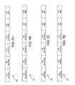
- FIGS. 7A-7D An example of how a header is changed in a packet sent from the second host 120 to the second sensor 360 in a rerouting scheme by the address-transparent device 310 is shown in FIGS. 7A-7D .
- the first host 110 or the second host 120 is able to access the tool 130 , but the first host 110 and the second host 120 will not be able to access the first sensor 350 or the second sensor 360 .
- the first and second sensors 350 , 360 are able to piggyback on the IP address of the tool 130 for communicating packets with the first and second hosts 110 , 120 .
- the second host 120 with the IP address of 10.10.10.6 sends a packet to the second sensor 360 having a port number 3236.
- a header 700 at this point in time is shown in FIG. 7A : a first field 702 containing a tool MAC address, a second field 704 containing a host MAC address, a third field 710 containing the IP address of the tool MAC 10.10.10.10.7, a fourth field 712 containing the IP address of the second host 10.10.20.6, a fifth field 714 containing the port number of the tool 5000, and a sixth field 716 containing a port number 3236 of the second host 120 .
- the address-transparent device 120 receives the packet from the second host 120 and reroutes the packet to the second sensor 360 .
- the original header 700 is now changed to a header 720 , as shown in FIG. 7B : a first field 722 containing a second sensor MAC address, a second field 724 containing an ATD MAC address, a third field 730 containing the subnet IP address 192.168.2.3 of the second sensor 360 , the fourth field 732 containing the subnet IP address 192.168.2.1 of the ATD 310 , the fifth field 734 containing the port number 5001 of the second sensor 360 , and the sixth field 736 containing the port number 6526 of the ATD 310 .
- the second sensor 360 receives the packet from the address-transparent device 120 and sends a reply to the address-transparent device 310 .
- the header 720 is now changed again to a header 740 , as shown in FIG. 7C : a first field 742 containing the ATD MAC address, a second field 744 containing the sensor MAC address, a third field 750 containing the subnet IP address 192.168.2.1 of the ATD 310 , the fourth field 752 containing the subnet IP address 192.168.2.3 of the second sensor 360 , the fifth field 754 containing the port number 6526 of the ATD 310 , and the sixth field 756 containing the port number 5001 of the second sensor 360 .
- the address-transparent device 310 receives the reply packet from the second sensor 360 and sends the reply packet to the second host 360 .
- the header 740 is changed once more to a header 760 , as shown in FIG. 7D : a first field 762 containing the host MAC address, a second field 764 containing the tool MAC address, a third field 770 containing the IP address 10.10.10.6 of the second host 120 , the fourth field 772 containing the IP address 10.10.10.7 of the tool 130 , the fifth field 774 containing the port number 3236 of the second host 120 , and the sixth field 776 containing the port number 5000 of the tool 130 .
- the rerouting feature of the address-transparent device 310 in the present invention allows additional services, such as sensors, to be added to a semiconductor fab without the expense of requiring additional IP addresses assigned to newly added devices.
- FIG. 8 is a flow chart illustrating the filtering process 800 in which the address-transparent device 310 performs in analyzing packets.
- the address-transparent device checks for its internal configuration. If the configuration is turned to an automatic mode, the process 800 operates in learning mode and detects for configuration data including the host 110 , the tool 130 and the port 5000 at step 814 . For instance, the address-transparent device 310 sniffs the network traffic and interpret packets for extracting pertinent information from a packet, such as retrieving the IP address and the port number of a HSMS packet for auto-configuring itself.
- the address-transparent device 310 reads a configuration file supplied by a source, such as the host 110 , for configuration the network in the semiconductor fab 300 . After the configuration settings have been set up, the address-transparent device 310 at step 820 wait for arrival of a packet either through the first port 320 or the second port 330 . At step 822 , the address-transparent device 310 receives the packet either from the first network 140 or the second network 340 . The address-transparent device 310 detects for the presence of a broadcast storm at step 830 . If the broadcast storm is found to be present, the address-transparent device 310 drops the packets at step 836 .
- a source such as the host 110
- the address-transparent device 310 checks whether a sniffer mode has been set up at step 832 .
- the address-transparent device 310 provides a copy of the packet for local use if the sniffer mode has been set. Otherwise, the process 800 proceeds to the next step if the address-transparent device 310 detects that the sniffer mode has not been set.
- the address-transparent device 310 determines whether the received packet is a reply to an intercepted or re-routed packet. If the received packet is a reply, at step 842 , the address-transparent device 310 changes the header of the received packet based on the header for the original packet. At step 844 , the address-transparent device 844 sends the packet back to the source where the original packet came from. The process 800 returns to the step 820 to wait for the next packet.
- the address-transparent device 310 analyzes the received packet at step 850 if the packet is not a reply to the intercepted or re-routed packet. The result of the analysis by the address-transparent device 310 determines whether the packet should be intercepted, re-routed or for other usage. If the determination is to intercept the packet, at step 860 , the address-transparent device 310 accepts the packet for use locally, i.e. the packet will be used by the data consumer 520 . The header of the packet will be saved at step 862 . If the determination is to reroute the packet, the address-transparent device 310 modifies the header of the packet at step 870 , saves the header at step 872 , and sends the packet to destination at step 874 .
- the address-transparent device 310 forwards the packet to another network if the determination of the packet is for other usage at step 876 .
- the process 800 returns to step 820 , either from step 862 after saving the header or from step 874 after the packet has been transmitted to another network.
- FIG. 9 is a block diagram of a semiconductor fab 900 illustrating an alternative embodiment in the implementation of an address-transparent device 910 and a failsafe switch 920 .
- the address-transparent device 920 comprises a LAN1 port, a LAN2 port, a third port and a fourth port.
- the failsafe switch 920 has a first port 921 connected to the third port of the address-transparent device 920 , a second port 922 connected to the fourth port of the address-transparent device 920 , a third port 923 connected to the first network interface 140 , and a fourth port 924 connected to the second network interface 340 .
- the third port 923 and the fourth port 924 of the address-transparent device 920 are activated for establishing connections between the first network 140 and the second network 340 when there is a failure detected by the address-transparent device 910 , which could be caused by a hardware malfunction or software stalled.
- Examples of the rerouting from the analyzing step 950 are shown below in the replacement of a header in a packet.
- the six fields 612 , 614 , 622 , 624 , 632 and 634 are replaced when rerouting a packet, i.e. replacing the destination MAC address with a new destination MAC address, replacing the source MAC address with a new source MAC address, replacing the destination IP address with a new IP address, replacing the source IP address with a new source IP address, replacing the destination port with a new destination port, and replacing a source port with a new port.
- the address-transparent device 310 has a configuration setting with a table that shows which header information is replaced with which header information.
- a source is communicating with a destination, which has the following six configuration entries: a packet is sent to: ⁇ network> ⁇ ip> ⁇ port> and re-routed: ⁇ network> ⁇ ip> ⁇ port>, where ⁇ Network> refers to LAN1 or LAN2, ⁇ ip> refers to an IP address, and ⁇ port> refers to a port number.
- the address space of LAN2 is represented as 192.168.2.x, while the address space of local is 127.0.0.1, where local means accepting a packet for local use by the data consumer 520 .
- a packet is directed to a destination (destination IP and destination port) 10.10.10.7:5000 from LAN1, the packet is rerouted to LAN2: 192.168.2.3:80.
- the packet reroutes the packet to local: 127.0.0.1:5000.
- the host 110 that is coupled to the first network 140 is also able to send a packet to multiple devices coupled to the second network 340 using the same IP address but a different port number.
- the address-transparent device 310 of the present invention can be implemented to operate in Layer 4 switching at the transport layer of the TCP/IP stack in the OSI (Open System Interconnection) model. It is apparent to one of skill in the art that the present invention can also be implemented to operate in Layer 2 switching that operates at the MAC (Media Access Control) layer, or Layer 3 switching that operates at the network layer, switching packets based on an IP address.
- OSI Open System Interconnection
Abstract
Description
Claims (23)
Priority Applications (7)
| Application Number | Priority Date | Filing Date | Title |
|---|---|---|---|
| US11/178,626 US7787477B2 (en) | 2005-07-11 | 2005-07-11 | Address-transparent device and method |
| TW095125103A TW200719637A (en) | 2005-07-11 | 2006-07-10 | Address-transparent device and method |
| PCT/US2006/026551 WO2007008683A2 (en) | 2005-07-11 | 2006-07-10 | Address-transparent device and method |
| CNA2006800254463A CN101223740A (en) | 2005-07-11 | 2006-07-10 | Address-transparent device and method |
| EP06774572A EP1902554A2 (en) | 2005-07-11 | 2006-07-10 | Address-transparent device and method |
| JP2008521471A JP2009502051A (en) | 2005-07-11 | 2006-07-10 | Address transparent apparatus and method |
| KR1020087003347A KR20080036080A (en) | 2005-07-11 | 2006-07-10 | Address-transparent device and method |
Applications Claiming Priority (1)
| Application Number | Priority Date | Filing Date | Title |
|---|---|---|---|
| US11/178,626 US7787477B2 (en) | 2005-07-11 | 2005-07-11 | Address-transparent device and method |
Publications (2)
| Publication Number | Publication Date |
|---|---|
| US20070008972A1 US20070008972A1 (en) | 2007-01-11 |
| US7787477B2 true US7787477B2 (en) | 2010-08-31 |
Family
ID=37618264
Family Applications (1)
| Application Number | Title | Priority Date | Filing Date |
|---|---|---|---|
| US11/178,626 Active 2028-03-13 US7787477B2 (en) | 2005-07-11 | 2005-07-11 | Address-transparent device and method |
Country Status (7)
| Country | Link |
|---|---|
| US (1) | US7787477B2 (en) |
| EP (1) | EP1902554A2 (en) |
| JP (1) | JP2009502051A (en) |
| KR (1) | KR20080036080A (en) |
| CN (1) | CN101223740A (en) |
| TW (1) | TW200719637A (en) |
| WO (1) | WO2007008683A2 (en) |
Cited By (3)
| Publication number | Priority date | Publication date | Assignee | Title |
|---|---|---|---|---|
| US20100022856A1 (en) * | 2008-07-28 | 2010-01-28 | Medtronic, Inc. | Implantable optical hemodynamic sensor including light transmission member |
| US9716688B1 (en) * | 2015-05-13 | 2017-07-25 | Parallels International Gmbh | VPN for containers and virtual machines in local area networks |
| US10185563B2 (en) * | 2014-03-24 | 2019-01-22 | Inesc Tec—Instituto De Engenharia De Sistemas E | Control module for multiple mixed-signal resources management |
Families Citing this family (25)
| Publication number | Priority date | Publication date | Assignee | Title |
|---|---|---|---|---|
| US7620516B2 (en) * | 2005-05-02 | 2009-11-17 | Mks Instruments, Inc. | Versatile semiconductor manufacturing controller with statistically repeatable response times |
| US8406239B2 (en) | 2005-10-03 | 2013-03-26 | Broadcom Corporation | Multi-wideband communications over multiple mediums |
| US7808985B2 (en) * | 2006-11-21 | 2010-10-05 | Gigle Networks Sl | Network repeater |
| EP1770870B1 (en) * | 2005-10-03 | 2019-04-03 | Avago Technologies International Sales Pte. Limited | Powerline communication device and method |
| US8213895B2 (en) * | 2005-10-03 | 2012-07-03 | Broadcom Europe Limited | Multi-wideband communications over multiple mediums within a network |
| US20070076666A1 (en) * | 2005-10-03 | 2007-04-05 | Riveiro Juan C | Multi-Wideband Communications over Power Lines |
| US7860146B2 (en) * | 2006-07-06 | 2010-12-28 | Gigle Networks, Inc. | Adaptative multi-carrier code division multiple access |
| US8885814B2 (en) | 2006-07-25 | 2014-11-11 | Broadcom Europe Limited | Feedback impedance control for driving a signal |
| US8102844B1 (en) * | 2006-09-21 | 2012-01-24 | Pivotal Systems Corporation | High-speed SECS message services (HSMS) pass-through including bypass |
| US8416790B1 (en) | 2007-02-05 | 2013-04-09 | World Wide Packets, Inc. | Processing Ethernet packets associated with packet tunnels |
| US8416789B1 (en) * | 2007-02-05 | 2013-04-09 | World Wide Packets, Inc. | Multipoint packet forwarding using packet tunnels |
| US7693164B1 (en) | 2007-02-05 | 2010-04-06 | World Wide Packets, Inc. | Configuring a packet tunnel network |
| US7795973B2 (en) | 2008-10-13 | 2010-09-14 | Gigle Networks Ltd. | Programmable gain amplifier |
| US7956689B2 (en) * | 2008-10-13 | 2011-06-07 | Broadcom Corporation | Programmable gain amplifier and transconductance compensation system |
| US8477794B2 (en) * | 2009-04-30 | 2013-07-02 | Elster Electricity, Llc | Multiple communications protocol routing in advanced metering infrastructure context |
| US8350718B2 (en) | 2010-05-04 | 2013-01-08 | Itron, Inc. | Secure collector diagnostic portal activation |
| WO2012031075A1 (en) * | 2010-09-01 | 2012-03-08 | Magnus Sorlander | Fail-safe switch for media insertion server in a broadcast stream |
| US9094309B2 (en) * | 2012-03-13 | 2015-07-28 | International Business Machines Corporation | Detecting transparent network communication interception appliances |
| US9288215B2 (en) | 2013-03-08 | 2016-03-15 | Itron, Inc. | Utilizing routing for secure transactions |
| US20150036548A1 (en) * | 2013-08-05 | 2015-02-05 | Alan Weir | System and method for recording calls in an ip-based communications system |
| TWI531908B (en) * | 2014-04-24 | 2016-05-01 | A method of supporting virtual machine migration with Software Defined Network (SDN) | |
| KR20150145687A (en) * | 2014-06-20 | 2015-12-30 | 삼성전자주식회사 | Scheme for packet compression in ip based broadcast network |
| CN107615444B (en) * | 2015-06-12 | 2021-06-15 | 株式会社富士 | Relay device and manufacturing system |
| US10389659B2 (en) * | 2017-09-27 | 2019-08-20 | Lam Research Corporation | Universal multiprotocol industrial data logger |
| US20220086730A1 (en) * | 2020-09-16 | 2022-03-17 | Qualcomm Incorporated | Unicast packet addressing and communication |
Citations (52)
| Publication number | Priority date | Publication date | Assignee | Title |
|---|---|---|---|---|
| US4736367A (en) | 1986-12-22 | 1988-04-05 | Chrysler Motors Corporation | Smart control and sensor devices single wire bus multiplex system |
| US5307463A (en) | 1990-03-08 | 1994-04-26 | Allen-Bradley Company, Inc. | Programmable controller communication module |
| US5469150A (en) | 1992-12-18 | 1995-11-21 | Honeywell Inc. | Sensor actuator bus system |
| US5657252A (en) | 1995-09-29 | 1997-08-12 | Motorola, Inc. | Dynamically configurable equipment integration architecture |
| US5751967A (en) | 1994-07-25 | 1998-05-12 | Bay Networks Group, Inc. | Method and apparatus for automatically configuring a network device to support a virtual network |
| US5805442A (en) | 1996-05-30 | 1998-09-08 | Control Technology Corporation | Distributed interface architecture for programmable industrial control systems |
| US5978753A (en) | 1997-03-18 | 1999-11-02 | Hewlett-Packard Company | Context parameters for establishing data communication patterns in a distributed control and measurement system |
| US5999530A (en) | 1995-10-12 | 1999-12-07 | 3Com Corporation | Method and apparatus for transparent intermediate system based filtering on a LAN of multicast packets |
| US5999536A (en) * | 1996-11-29 | 1999-12-07 | Anritsu Corporation | Router for high-speed packet communication between terminal apparatuses in different LANs |
| US6002996A (en) | 1997-11-26 | 1999-12-14 | The Johns Hopkins University | Networked sensor system |
| US6233613B1 (en) | 1997-08-18 | 2001-05-15 | 3Com Corporation | High impedance probe for monitoring fast ethernet LAN links |
| US6237112B1 (en) | 1997-07-10 | 2001-05-22 | Samsung Electronics Co., Ltd. | SCSI device available for breakdown prediction and self-examination and a method thereof |
| US6282576B1 (en) | 1998-09-21 | 2001-08-28 | Unisys Corporation | Method of transferring heterogeneous data with meaningful interrelationships between incompatible computers |
| US6300787B1 (en) | 2000-05-01 | 2001-10-09 | Hewlett-Packard Company | System and method for observing information transmitted between two integrated circuits |
| US20020002560A1 (en) | 2000-06-30 | 2002-01-03 | Snehanshu Shah | Method and system for collecting diverse data types within a manufacturing environment and accessing the diverse data types through a network portal |
| US20020154233A1 (en) | 2000-05-08 | 2002-10-24 | Shinichi Yoshimura | Imaging device ,and its drive control method |
| US20020174340A1 (en) | 2001-05-18 | 2002-11-21 | Dick Kevin Stewart | System, method and computer program product for auditing XML messages in a network-based message stream |
| US20020196802A1 (en) | 1998-02-26 | 2002-12-26 | Joshua Sakov | Data forwarding method and apparatus |
| US6505256B1 (en) | 1999-01-15 | 2003-01-07 | Compaq Information Technologies Group, L.P. | Automatic synchronization of state colors across a web-based system |
| US20030033032A1 (en) | 2001-07-02 | 2003-02-13 | Lind Michael A. | Application specific intelligent microsensors |
| US6538990B1 (en) * | 1999-04-15 | 2003-03-25 | International Business Machines Corporation | Method and system for congestion flow control in a high speed network |
| US20030063611A1 (en) * | 2001-09-28 | 2003-04-03 | Marc Schaub | Flexible application of mapping algorithms within a packet distributor |
| US6591310B1 (en) | 2000-05-11 | 2003-07-08 | Lsi Logic Corporation | Method of responding to I/O request and associated reply descriptor |
| US20030140248A1 (en) * | 2002-01-24 | 2003-07-24 | David Izatt | Undetectable firewall |
| US6604010B2 (en) | 1998-04-11 | 2003-08-05 | Samsung Electronics Co., Ltd. | System for selectively managing workpieces and a method for controlling the same |
| US6609076B2 (en) | 2001-09-28 | 2003-08-19 | Claud S. Gordon Company | Interface device and method of use with a smart sensor |
| US6649416B1 (en) | 2000-02-18 | 2003-11-18 | Trustees Of Tufts College | Intelligent electro-optical sensor array and method for analyte detection |
| US6650955B1 (en) | 2001-12-18 | 2003-11-18 | Advanced Micro Devices, Inc. | Method and apparatus for determining a sampling plan based on process and equipment fingerprinting |
| US6711731B2 (en) | 2000-08-23 | 2004-03-23 | Pri Automation, Inc. | Web based tool control in a semiconductor fabrication facility |
| US6747979B1 (en) | 1998-10-27 | 2004-06-08 | Hewlett-Packard Development Company, L.C. | Method and apparatus for bridging between networks |
| US6757681B1 (en) | 1998-06-02 | 2004-06-29 | International Business Machines Corporation | Method and system for providing performance data |
| US6757714B1 (en) | 2000-07-28 | 2004-06-29 | Axeda Systems Operating Company, Inc. | Reporting the state of an apparatus to a remote computer |
| US20040144927A1 (en) | 2003-01-28 | 2004-07-29 | Auner Gregory W. | Microsystems arrays for digital radiation imaging and signal processing and method for making microsystem arrays |
| US6801878B1 (en) | 1999-04-08 | 2004-10-05 | George Mason University | System and method for managing sensors of a system |
| US6826439B1 (en) | 2000-05-23 | 2004-11-30 | Advanced Micro Devices, Inc. | Broadband distribution of SECS-II data |
| US6834211B1 (en) | 2002-10-31 | 2004-12-21 | Advanced Micro Devices, Inc. | Adjusting a trace data rate based upon a tool state |
| US20050018693A1 (en) * | 2003-06-27 | 2005-01-27 | Broadcom Corporation | Fast filtering processor for a highly integrated network device |
| US6871112B1 (en) | 2000-01-07 | 2005-03-22 | Advanced Micro Devices, Inc. | Method for requesting trace data reports from FDC semiconductor fabrication processes |
| US6895572B2 (en) | 1999-03-12 | 2005-05-17 | Omron Corporation | Sensors |
| US20050111434A1 (en) | 2003-11-06 | 2005-05-26 | Joacim Halen | Adaptable network bridge |
| US20050125692A1 (en) * | 2003-12-04 | 2005-06-09 | Cox Brian F. | 802.1X authentication technique for shared media |
| US6907008B1 (en) | 1999-12-21 | 2005-06-14 | Nortel Networks Limited | Method for a network device inserted between point to point connected stations to automatically negotiate communication parameters between the stations |
| US20050182968A1 (en) * | 2002-01-24 | 2005-08-18 | David Izatt | Intelligent firewall |
| US20050259654A1 (en) * | 2004-04-08 | 2005-11-24 | Faulk Robert L Jr | Dynamic access control lists |
| US6970758B1 (en) | 2001-07-12 | 2005-11-29 | Advanced Micro Devices, Inc. | System and software for data collection and process control in semiconductor manufacturing and method thereof |
| US6980547B1 (en) * | 2000-10-31 | 2005-12-27 | Intel Corporation | Distributed switch/router silicon engine |
| US20060002306A1 (en) * | 2004-06-30 | 2006-01-05 | Ronald Brown | Failure detection of path information corresponding to a transmission path |
| US7003367B2 (en) | 2001-12-26 | 2006-02-21 | National Science Council | Equipment management method |
| US7072985B1 (en) | 2001-05-02 | 2006-07-04 | Mks Instruments, Inc. | Method and apparatus for two phase structured message to tagged message translation |
| US20060259259A1 (en) | 2005-05-02 | 2006-11-16 | Mks Instruments, Inc. | Versatile semiconductor manufacturing controller with statistically repeatable response times |
| US7286528B1 (en) * | 2001-12-12 | 2007-10-23 | Marvell International Ltd. | Multiple address databases in a switch without the need for extra memory |
| US7382778B2 (en) * | 2004-01-05 | 2008-06-03 | Tropos Networks, Inc. | Link layer emulation |
Family Cites Families (1)
| Publication number | Priority date | Publication date | Assignee | Title |
|---|---|---|---|---|
| JP4118489B2 (en) * | 2000-04-20 | 2008-07-16 | 東海旅客鉄道株式会社 | LAN repeater |
-
2005
- 2005-07-11 US US11/178,626 patent/US7787477B2/en active Active
-
2006
- 2006-07-10 WO PCT/US2006/026551 patent/WO2007008683A2/en active Application Filing
- 2006-07-10 CN CNA2006800254463A patent/CN101223740A/en active Pending
- 2006-07-10 EP EP06774572A patent/EP1902554A2/en not_active Withdrawn
- 2006-07-10 KR KR1020087003347A patent/KR20080036080A/en active IP Right Grant
- 2006-07-10 TW TW095125103A patent/TW200719637A/en unknown
- 2006-07-10 JP JP2008521471A patent/JP2009502051A/en active Pending
Patent Citations (54)
| Publication number | Priority date | Publication date | Assignee | Title |
|---|---|---|---|---|
| US4736367A (en) | 1986-12-22 | 1988-04-05 | Chrysler Motors Corporation | Smart control and sensor devices single wire bus multiplex system |
| US5307463A (en) | 1990-03-08 | 1994-04-26 | Allen-Bradley Company, Inc. | Programmable controller communication module |
| US5469150A (en) | 1992-12-18 | 1995-11-21 | Honeywell Inc. | Sensor actuator bus system |
| US5751967A (en) | 1994-07-25 | 1998-05-12 | Bay Networks Group, Inc. | Method and apparatus for automatically configuring a network device to support a virtual network |
| US5657252A (en) | 1995-09-29 | 1997-08-12 | Motorola, Inc. | Dynamically configurable equipment integration architecture |
| US5999530A (en) | 1995-10-12 | 1999-12-07 | 3Com Corporation | Method and apparatus for transparent intermediate system based filtering on a LAN of multicast packets |
| US5805442A (en) | 1996-05-30 | 1998-09-08 | Control Technology Corporation | Distributed interface architecture for programmable industrial control systems |
| US5999536A (en) * | 1996-11-29 | 1999-12-07 | Anritsu Corporation | Router for high-speed packet communication between terminal apparatuses in different LANs |
| US5978753A (en) | 1997-03-18 | 1999-11-02 | Hewlett-Packard Company | Context parameters for establishing data communication patterns in a distributed control and measurement system |
| US6237112B1 (en) | 1997-07-10 | 2001-05-22 | Samsung Electronics Co., Ltd. | SCSI device available for breakdown prediction and self-examination and a method thereof |
| US6233613B1 (en) | 1997-08-18 | 2001-05-15 | 3Com Corporation | High impedance probe for monitoring fast ethernet LAN links |
| US6002996A (en) | 1997-11-26 | 1999-12-14 | The Johns Hopkins University | Networked sensor system |
| US20020196802A1 (en) | 1998-02-26 | 2002-12-26 | Joshua Sakov | Data forwarding method and apparatus |
| US6604010B2 (en) | 1998-04-11 | 2003-08-05 | Samsung Electronics Co., Ltd. | System for selectively managing workpieces and a method for controlling the same |
| US6757681B1 (en) | 1998-06-02 | 2004-06-29 | International Business Machines Corporation | Method and system for providing performance data |
| US6282576B1 (en) | 1998-09-21 | 2001-08-28 | Unisys Corporation | Method of transferring heterogeneous data with meaningful interrelationships between incompatible computers |
| US6747979B1 (en) | 1998-10-27 | 2004-06-08 | Hewlett-Packard Development Company, L.C. | Method and apparatus for bridging between networks |
| US6505256B1 (en) | 1999-01-15 | 2003-01-07 | Compaq Information Technologies Group, L.P. | Automatic synchronization of state colors across a web-based system |
| US6895572B2 (en) | 1999-03-12 | 2005-05-17 | Omron Corporation | Sensors |
| US6801878B1 (en) | 1999-04-08 | 2004-10-05 | George Mason University | System and method for managing sensors of a system |
| US6538990B1 (en) * | 1999-04-15 | 2003-03-25 | International Business Machines Corporation | Method and system for congestion flow control in a high speed network |
| US6907008B1 (en) | 1999-12-21 | 2005-06-14 | Nortel Networks Limited | Method for a network device inserted between point to point connected stations to automatically negotiate communication parameters between the stations |
| US6871112B1 (en) | 2000-01-07 | 2005-03-22 | Advanced Micro Devices, Inc. | Method for requesting trace data reports from FDC semiconductor fabrication processes |
| US6649416B1 (en) | 2000-02-18 | 2003-11-18 | Trustees Of Tufts College | Intelligent electro-optical sensor array and method for analyte detection |
| US6300787B1 (en) | 2000-05-01 | 2001-10-09 | Hewlett-Packard Company | System and method for observing information transmitted between two integrated circuits |
| US20020154233A1 (en) | 2000-05-08 | 2002-10-24 | Shinichi Yoshimura | Imaging device ,and its drive control method |
| US6591310B1 (en) | 2000-05-11 | 2003-07-08 | Lsi Logic Corporation | Method of responding to I/O request and associated reply descriptor |
| US6826439B1 (en) | 2000-05-23 | 2004-11-30 | Advanced Micro Devices, Inc. | Broadband distribution of SECS-II data |
| US20020002560A1 (en) | 2000-06-30 | 2002-01-03 | Snehanshu Shah | Method and system for collecting diverse data types within a manufacturing environment and accessing the diverse data types through a network portal |
| US6757714B1 (en) | 2000-07-28 | 2004-06-29 | Axeda Systems Operating Company, Inc. | Reporting the state of an apparatus to a remote computer |
| US6711731B2 (en) | 2000-08-23 | 2004-03-23 | Pri Automation, Inc. | Web based tool control in a semiconductor fabrication facility |
| US6980547B1 (en) * | 2000-10-31 | 2005-12-27 | Intel Corporation | Distributed switch/router silicon engine |
| US7072985B1 (en) | 2001-05-02 | 2006-07-04 | Mks Instruments, Inc. | Method and apparatus for two phase structured message to tagged message translation |
| US20020174340A1 (en) | 2001-05-18 | 2002-11-21 | Dick Kevin Stewart | System, method and computer program product for auditing XML messages in a network-based message stream |
| US6889165B2 (en) | 2001-07-02 | 2005-05-03 | Battelle Memorial Institute | Application specific intelligent microsensors |
| US20030033032A1 (en) | 2001-07-02 | 2003-02-13 | Lind Michael A. | Application specific intelligent microsensors |
| US6970758B1 (en) | 2001-07-12 | 2005-11-29 | Advanced Micro Devices, Inc. | System and software for data collection and process control in semiconductor manufacturing and method thereof |
| US7190695B2 (en) * | 2001-09-28 | 2007-03-13 | Lucent Technologies Inc. | Flexible application of mapping algorithms within a packet distributor |
| US6609076B2 (en) | 2001-09-28 | 2003-08-19 | Claud S. Gordon Company | Interface device and method of use with a smart sensor |
| US20030063611A1 (en) * | 2001-09-28 | 2003-04-03 | Marc Schaub | Flexible application of mapping algorithms within a packet distributor |
| US7286528B1 (en) * | 2001-12-12 | 2007-10-23 | Marvell International Ltd. | Multiple address databases in a switch without the need for extra memory |
| US6650955B1 (en) | 2001-12-18 | 2003-11-18 | Advanced Micro Devices, Inc. | Method and apparatus for determining a sampling plan based on process and equipment fingerprinting |
| US7003367B2 (en) | 2001-12-26 | 2006-02-21 | National Science Council | Equipment management method |
| US20050182968A1 (en) * | 2002-01-24 | 2005-08-18 | David Izatt | Intelligent firewall |
| US20030140248A1 (en) * | 2002-01-24 | 2003-07-24 | David Izatt | Undetectable firewall |
| US6834211B1 (en) | 2002-10-31 | 2004-12-21 | Advanced Micro Devices, Inc. | Adjusting a trace data rate based upon a tool state |
| US20040144927A1 (en) | 2003-01-28 | 2004-07-29 | Auner Gregory W. | Microsystems arrays for digital radiation imaging and signal processing and method for making microsystem arrays |
| US20050018693A1 (en) * | 2003-06-27 | 2005-01-27 | Broadcom Corporation | Fast filtering processor for a highly integrated network device |
| US20050111434A1 (en) | 2003-11-06 | 2005-05-26 | Joacim Halen | Adaptable network bridge |
| US20050125692A1 (en) * | 2003-12-04 | 2005-06-09 | Cox Brian F. | 802.1X authentication technique for shared media |
| US7382778B2 (en) * | 2004-01-05 | 2008-06-03 | Tropos Networks, Inc. | Link layer emulation |
| US20050259654A1 (en) * | 2004-04-08 | 2005-11-24 | Faulk Robert L Jr | Dynamic access control lists |
| US20060002306A1 (en) * | 2004-06-30 | 2006-01-05 | Ronald Brown | Failure detection of path information corresponding to a transmission path |
| US20060259259A1 (en) | 2005-05-02 | 2006-11-16 | Mks Instruments, Inc. | Versatile semiconductor manufacturing controller with statistically repeatable response times |
Non-Patent Citations (23)
| Title |
|---|
| "MyFab2k-tour," http:/www.ipc-kallmuenz.de/tour1.htm, 6 pages. |
| Consilium, White Paper: Overall Equipment Effectiveness, http://www.consilium.com/white-oee.html, 1998-2000, 12 pages, Consilium, Inc. |
| GW Associates, Inc., "GWconX300 Communications Software for 300mm Equipment Data Sheet," 2001, 3 pages, USA. |
| GW Associates, Inc., "SDR SECS Driver Software," http://www.gwainc.com/products/sdr.htm, 6 pages. |
| International Search Report for International Application No. PCT/US05/11527 mailed on Nov. 23, 2006. |
| International Search Report for International Application No. PCT/US05/11527 mailed on Oct. 12, 2006. |
| IPC, "MyFab2k.com," http://www.ipc-kallenz.de/, 3 pages. |
| J. Moyne, N. Najafi, D. Judd, and A. Stock, "Analysis of Sensor/Actuator Bus Interoperability Standard Alternatives for Semiconductor Manufacturing," Published in Sensors Expo Conference Proceedings, Sep. 1994, 13 pages. |
| Office Action mailed Apr. 21, 2005, U.S. Appl. No. 09/935,213. |
| Office Action mailed Apr. 5, 2006, U.S. Appl. No. 09/935,213. |
| Office Action mailed May 4, 2005, U.S. Appl. 09/847,937. |
| Office Action mailed Nov. 15, 2005, U.S. Appl. No. 09/935,213. |
| Office Action mailed Oct. 20, 2004, U.S. Appl. No. 09/935,213. |
| Office Action mailed Oct. 5, 2004, U.S. Appl. 09/847,937. |
| Office Action mailed Sep. 22, 2005, U.S. Appl. No. 10/819,903. |
| P. Singer, "E-Diagnostics: Monitoring Tool Performance," Cahners Semiconductor International, http://www.semiconductor.net/semiconductors/issus/issues/2001/200103/six010301supp.asp, 2001, 9 pages. |
| Prof. Dr.-Ing. K. Etschberger, "Controller Area Network -Introduction," http://www.ixxat.de/english/knowhow/literatur/can.shtml, 2000, 10 pages, IXXAT Automation GmbH. |
| SEMI E37-0298, "High-Speed SECS Message Services (HSMS) Generic Services," 1995/1998, 24 pages, Semiconductor Equipment and Materials International (SEMI). |
| SEMI E4-0699, "SEMI Equipment Communications Standard 1 Message Transfer (SECS-I)," 1980/1999, 20 pages, Semiconductor Equipment and Materials International (SEMI). |
| SEMI E54-0997, "Sensor/Actuator Network Standard," 1997, 10 pages, Semiconductor Equipment and Materials International (SEMI). |
| SEMI ES-0600, "Semi Equipment Communications Standard 2 Message Content (SECS-II)," 1982/2000, pp. 1-15, 92-93, Semiconductor Equipment and Materials International (SEMI). |
| SI Automation, "The SECS Pack-Product Summar/The Silverbox-Product Summary," http://www.siautomation.com/index1.html, 2000, 4 pages. |
| Symphony Systems, "Symphony Systems Effective Ptoductivity Solutions (EPS)," http://www.symphony-systems.com/products/, 10 pages. |
Cited By (3)
| Publication number | Priority date | Publication date | Assignee | Title |
|---|---|---|---|---|
| US20100022856A1 (en) * | 2008-07-28 | 2010-01-28 | Medtronic, Inc. | Implantable optical hemodynamic sensor including light transmission member |
| US10185563B2 (en) * | 2014-03-24 | 2019-01-22 | Inesc Tec—Instituto De Engenharia De Sistemas E | Control module for multiple mixed-signal resources management |
| US9716688B1 (en) * | 2015-05-13 | 2017-07-25 | Parallels International Gmbh | VPN for containers and virtual machines in local area networks |
Also Published As
| Publication number | Publication date |
|---|---|
| EP1902554A2 (en) | 2008-03-26 |
| JP2009502051A (en) | 2009-01-22 |
| TW200719637A (en) | 2007-05-16 |
| WO2007008683A2 (en) | 2007-01-18 |
| US20070008972A1 (en) | 2007-01-11 |
| WO2007008683A3 (en) | 2007-04-05 |
| KR20080036080A (en) | 2008-04-24 |
| CN101223740A (en) | 2008-07-16 |
Similar Documents
| Publication | Publication Date | Title |
|---|---|---|
| US7787477B2 (en) | Address-transparent device and method | |
| JP4598072B2 (en) | Fail-safe switching method and device for intelligent controller | |
| US9405285B2 (en) | Interface for local configuration and monitoring of an industrial field device with support for provisioning onto an industrial wireless network and related system and method | |
| US7693687B2 (en) | Controller and method to mediate data collection from smart sensors for fab applications | |
| US20150289309A1 (en) | Adapter device for coupling an industrial field instrument to an industrial wireless network and related system and method | |
| US9185053B2 (en) | Virtual fault tolerant ethernet appliance and method of operation | |
| JP2022046438A (en) | Network resource management in communication system for control and automation systems | |
| CN105404207A (en) | Industrial environment vulnerability discovering device and method | |
| Paul et al. | Towards the protection of industrial control systems–conclusions of a vulnerability analysis of profinet IO | |
| CN116458132A (en) | Method and system for providing time critical services by means of a process control environment | |
| US8102844B1 (en) | High-speed SECS message services (HSMS) pass-through including bypass | |
| CN105553973A (en) | System and method for detecting industrial control equipment abnormality | |
| US20180324150A1 (en) | Integrated pcs functional competency assessment | |
| EP3905595B1 (en) | Industrial control system monitoring method, device and system, and computer-readable medium | |
| JP4811884B2 (en) | Method and apparatus for routing data packets between different Internet communication stack instances | |
| WO2020005475A1 (en) | Controlling communications between a plant network and a business network | |
| CN100487662C (en) | Failsafe switching of intelligent controller method and device | |
| WO2023019566A1 (en) | Control circuit and distributed control system | |
| KR20030026740A (en) | Method for network address transaction processing using the media access control | |
| Bykasov et al. | Trust Conditions for Active Scanning Methods for Finding Vulnerabilities in ICS Networks | |
| US20130054785A1 (en) | Communications path discovery | |
| JP2001237909A (en) | Data transmission device |
Legal Events
| Date | Code | Title | Description |
|---|---|---|---|
| AS | Assignment |
Owner name: MKS INSTRUMENTS, INC., MASSACHUSETTS Free format text: ASSIGNMENT OF ASSIGNORS INTEREST;ASSIGNORS:SIFNATSCH, GUENTER;RICHTER, MATTHEW;MAKHOTA, MAXYM;REEL/FRAME:016773/0808 Effective date: 20050711 |
|
| AS | Assignment |
Owner name: MKS INSTRUMENTS, INC., MASSACHUSETTS Free format text: ASSIGNMENT OF ASSIGNORS INTEREST;ASSIGNORS:SIFNATSCH, GUENTER;RICHTER, MATTHEW;MAKHOTA, MAXYM;REEL/FRAME:018079/0113 Effective date: 20050711 |
|
| STCF | Information on status: patent grant |
Free format text: PATENTED CASE |
|
| FPAY | Fee payment |
Year of fee payment: 4 |
|
| AS | Assignment |
Owner name: BARCLAYS BANK PLC, NEW YORK Free format text: SECURITY AGREEMENT;ASSIGNORS:MKS INSTRUMENTS, INC.;NEWPORT CORPORATION;REEL/FRAME:038663/0139 Effective date: 20160429 Owner name: DEUTSCHE BANK AG NEW YORK BRANCH, NEW YORK Free format text: SECURITY AGREEMENT;ASSIGNORS:MKS INSTRUMENTS, INC.;NEWPORT CORPORATION;REEL/FRAME:038663/0265 Effective date: 20160429 |
|
| MAFP | Maintenance fee payment |
Free format text: PAYMENT OF MAINTENANCE FEE, 8TH YEAR, LARGE ENTITY (ORIGINAL EVENT CODE: M1552) Year of fee payment: 8 |
|
| AS | Assignment |
Owner name: BARCLAYS BANK PLC, AS COLLATERAL AGENT, NEW YORK Free format text: PATENT SECURITY AGREEMENT (ABL);ASSIGNORS:ELECTRO SCIENTIFIC INDUSTRIES, INC.;MKS INSTRUMENTS, INC.;NEWPORT CORPORATION;REEL/FRAME:048211/0312 Effective date: 20190201 Owner name: MKS INSTRUMENTS, INC., MASSACHUSETTS Free format text: RELEASE BY SECURED PARTY;ASSIGNOR:DEUTSCHE BANK AG NEW YORK BRANCH;REEL/FRAME:048226/0095 Effective date: 20190201 Owner name: NEWPORT CORPORATION, CALIFORNIA Free format text: RELEASE BY SECURED PARTY;ASSIGNOR:DEUTSCHE BANK AG NEW YORK BRANCH;REEL/FRAME:048226/0095 Effective date: 20190201 |
|
| AS | Assignment |
Owner name: BARCLAYS BANK PLC, AS COLLATERAL AGENT, NEW YORK Free format text: CORRECTIVE ASSIGNMENT TO CORRECT THE REMOVE U.S. PATENT NO.7,919,646 PREVIOUSLY RECORDED ON REEL 048211 FRAME 0312. ASSIGNOR(S) HEREBY CONFIRMS THE PATENT SECURITY AGREEMENT (ABL);ASSIGNORS:ELECTRO SCIENTIFIC INDUSTRIES, INC.;MKS INSTRUMENTS, INC.;NEWPORT CORPORATION;REEL/FRAME:055668/0687 Effective date: 20190201 |
|
| MAFP | Maintenance fee payment |
Free format text: PAYMENT OF MAINTENANCE FEE, 12TH YEAR, LARGE ENTITY (ORIGINAL EVENT CODE: M1553); ENTITY STATUS OF PATENT OWNER: LARGE ENTITY Year of fee payment: 12 |
|
| AS | Assignment |
Owner name: JPMORGAN CHASE BANK, N.A., AS COLLATERAL AGENT, ILLINOIS Free format text: SECURITY INTEREST;ASSIGNORS:MKS INSTRUMENTS, INC.;NEWPORT CORPORATION;ELECTRO SCIENTIFIC INDUSTRIES, INC.;REEL/FRAME:061572/0069 Effective date: 20220817 |
|
| AS | Assignment |
Owner name: ELECTRO SCIENTIFIC INDUSTRIES, INC., OREGON Free format text: RELEASE BY SECURED PARTY;ASSIGNOR:BARCLAYS BANK PLC;REEL/FRAME:063009/0001 Effective date: 20220817 Owner name: NEWPORT CORPORATION, MASSACHUSETTS Free format text: RELEASE BY SECURED PARTY;ASSIGNOR:BARCLAYS BANK PLC;REEL/FRAME:063009/0001 Effective date: 20220817 Owner name: MKS INSTRUMENTS, INC., MASSACHUSETTS Free format text: RELEASE BY SECURED PARTY;ASSIGNOR:BARCLAYS BANK PLC;REEL/FRAME:063009/0001 Effective date: 20220817 Owner name: ELECTRO SCIENTIFIC INDUSTRIES, INC., OREGON Free format text: RELEASE BY SECURED PARTY;ASSIGNOR:BARCLAYS BANK PLC;REEL/FRAME:062739/0001 Effective date: 20220817 Owner name: NEWPORT CORPORATION, MASSACHUSETTS Free format text: RELEASE BY SECURED PARTY;ASSIGNOR:BARCLAYS BANK PLC;REEL/FRAME:062739/0001 Effective date: 20220817 Owner name: MKS INSTRUMENTS, INC., MASSACHUSETTS Free format text: RELEASE BY SECURED PARTY;ASSIGNOR:BARCLAYS BANK PLC;REEL/FRAME:062739/0001 Effective date: 20220817 |