US7791017B2 - Method to simultaneously determine pore hydrocarbon density and water saturation from pulsed neutron measurements - Google Patents
Method to simultaneously determine pore hydrocarbon density and water saturation from pulsed neutron measurements Download PDFInfo
- Publication number
- US7791017B2 US7791017B2 US11/781,404 US78140407A US7791017B2 US 7791017 B2 US7791017 B2 US 7791017B2 US 78140407 A US78140407 A US 78140407A US 7791017 B2 US7791017 B2 US 7791017B2
- Authority
- US
- United States
- Prior art keywords
- inelastic
- density
- ratio
- water saturation
- formation
- Prior art date
- Legal status (The legal status is an assumption and is not a legal conclusion. Google has not performed a legal analysis and makes no representation as to the accuracy of the status listed.)
- Active
Links
Images


Classifications
-
- G—PHYSICS
- G01—MEASURING; TESTING
- G01V—GEOPHYSICS; GRAVITATIONAL MEASUREMENTS; DETECTING MASSES OR OBJECTS; TAGS
- G01V5/00—Prospecting or detecting by the use of nuclear radiation, e.g. of natural or induced radioactivity
- G01V5/04—Prospecting or detecting by the use of nuclear radiation, e.g. of natural or induced radioactivity specially adapted for well-logging
- G01V5/08—Prospecting or detecting by the use of nuclear radiation, e.g. of natural or induced radioactivity specially adapted for well-logging using primary nuclear radiation sources or X-rays
- G01V5/12—Prospecting or detecting by the use of nuclear radiation, e.g. of natural or induced radioactivity specially adapted for well-logging using primary nuclear radiation sources or X-rays using gamma or X-ray sources
- G01V5/125—Prospecting or detecting by the use of nuclear radiation, e.g. of natural or induced radioactivity specially adapted for well-logging using primary nuclear radiation sources or X-rays using gamma or X-ray sources and detecting the secondary gamma- or X-rays in different places along the bore hole
Definitions
- the present invention relates to the downhole measurement of substances in earth formations surrounding an earth borehole.
- Neutron generators based on the deuteron-triton fusion reaction produce neutrons at an energy slightly over 14 MeV. At this energy, the probability of scattering from hydrogen is greatly reduced from that at epithermal energy, while the probability of inelastically scattering from heavier nuclei, like silicon, calcium, carbon and oxygen is greatly increased from that at lower energy. Consequently, scattering and energy loss are not dominated by hydrogen until the energy of the neutrons drops to approximately 6 MeV. By that time, the slowing down length (L h ) of the neutrons has already been heavily influenced by inelastic scattering.
- the transport of high energy neutrons is determined not only by hydrogen index, but also, to a large degree, by the density of inelastic scatterers and the inelastic scattering cross section of these nuclei.
- the slowing down of high energy neutrons relevant to inelastic scattering can be described by the (L h ) from 14 MeV to 1 MeV, which is similar to the conventional slowing down length (L s ), except that the latter extends down to thermal energy.
- L h the neutron flux at 1 MeV is proportional to
- the detection probability is high when the gamma-rays are produced close to the detector, the detection rate for detectors at distances r n and r f from the neutron source (where r n is the distance to the near detector and r f is the distance to the far detector) will be modulated by
- inelastic scatterers e.g., carbon or oxygen
- L h the density of inelastic scatterers
- U.S. Pat. No. 6,805,195B2 to Vinegar, et al. discloses that a hydrocarbon containing formation may be treated using an in situ thermal process. A mixture of hydrocarbons, H 2 , and/or other formation fluids may be produced from the formation. Heat may be applied to the formation to raise a temperature of a portion of the formation to a pyrolysis temperature. After pyrolysis, the portion may be heated to a synthesis gas production temperature. A synthesis gas producing fluid may be introduced into the portion to generate synthesis gas. Synthesis gas may be produced from the formation in a batch manner or in a substantially continuous manner.
- U.S. Pat. No. 6,769,485B2 to Vinegar, et al. discloses that a coal formation may be treated using an in situ thermal process. Hydrocarbons, H 2 , and/or other formation fluids may be produced from the formation. Heat may be applied to the formation to raise a temperature of a portion of the formation to a synthesis gas production temperature. A synthesis gas producing fluid may be introduced into the formation to generate synthesis gas. Production wells may be operated at selected temperatures to obtain a desired synthesis gas composition.
- U.S. Pat. No. 6,761,216B2 to Vinegar, et al. discloses that a coal formation may be treated using an in situ thermal process.
- a mixture of hydrocarbons, H 2 , and/or other formation fluids may be produced from the formation.
- Heat may be applied to the formation to raise a temperature of a portion of the formation to a pyrolysis temperature.
- the portion may be heated to a synthesis gas production temperature.
- a synthesis gas producing fluid may be introduced into the portion to generate synthesis gas.
- Synthesis gas may be produced from the formation in a batch manner or in a substantially continuous manner.
- U.S. Pat. No. 6,732,796B2 to Vinegar, et al. discloses that a hydrocarbon containing formation may be treated using an in situ thermal process. A mixture of hydrocarbons, H 2 , and/or other formation fluids may be produced from the formation. Heat may be applied to the formation to raise a temperature of a portion of the formation to a pyrolysis temperature. A portion of a formation may be heated from a plurality of heat sources to a temperature sufficient to allow generation of a first synthesis gas having a low H 2 to CO ratio. A second portion of a formation may generate synthesis gas having a H 2 to CO ratio greater than the first synthesis gas. A portion of the first synthesis gas may be blended with a portion of the second synthesis gas to produce a blend synthesis gas having a desired H 2 to CO ratio.
- a method comprises using gamma-ray count rates from two detectors in a borehole logging tool, determining formation saturation of a first fluid using the gamma-ray count rates, determining formation saturation and density of a second fluid using said gamma-ray count rates and transmitting the saturation of the first fluid and the formation saturation and density of the second fluid to a surface receiver.
- the method may also comprise separating the second fluid into the volume fraction of the two phases.
- the second fluid may be a mixture of oil and hydrocarbon and the method may further comprise determining the water saturation of the first fluid.
- the first fluid may be oil and the second fluid may be a mixture of liquid and vapor water.
- the borehole is filled with air or gas, the method further comprising receiving a hydrogen sensitive signal.
- the hydrogen sensitive signal is received by one or more thermal neutron detectors.
- the hydrogen sensitive signal is received by a near:far gamma ray ratio.
- the method comprises using inelastic and capture gamma-ray count rates from two detectors in a borehole logging tool; determining formation water saturation; and transmitting the formation water saturation to a surface receiver.
- the method further comprises determining pore hydrocarbon density.
- the method further comprises determining formation water saturation and pore hydrocarbon density from a near:far inelastic gamma-ray ratio and a ratio of the carbon inelastic yield to a normalization inelastic yield.
- the normalization element is selected from the group comprising oxygen, silicon, calcium, iron.
- the normalization element is a combination of elements selected from the group comprising oxygen, silicon, calcium, iron.
- the method further comprises deriving the pore carbon density from a near:far inelastic gamma-ray ratio and a ratio of the carbon inelastic yield to a normalization inelastic yield.
- the normalization element is selected from the group consisting of oxygen, silicon, calcium, iron.
- the normalization element is a combination of measured elements selected from the group consisting of oxygen, silicon, calcium, iron.
- a hydrocarbon ratio is derived by measuring neutron porosity, measuring true porosity and capturing spectroscopy data.
- the method further comprises deriving true porosity from inelastic ratios.
- an apparatus comprising a borehole logging tool, and at least two detectors in the borehole logging tool for receiving gamma ray counts.
- the gamma ray counts are used to determine the formation saturation of a first fluid and the determining formation saturation and density of a second fluid.
- the volume fraction of the two phases of the second fluid is calculated.
- the water saturation of the first fluid is determined when the second fluid is a mixture of oil and hydrocarbon.
- FIG. 1 is a chart comparing the CH4 calculation to the CH2 calculation at the same hydrocarbon density, 0.2 g/cm3.
- FIG. 2 is a chart of the near:far ratio of a combination of inelastic gamma-rays.
- FIG. 3 is a chart of the near:far ratios for water and oil.
- FIG. 4 a comparison between the hydrocarbon density and water saturation derived from the method in this invention and the conventional open hole interpretation is shown.
- FIG. 5 is a plot of a model for a steam-injected heavy oil formation.
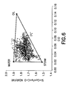
- FIG. 6 is a triangle plot of a well log in a steam flooded formation is shown.
- FIG. 7 is a plot of the Values of SS (steam saturation), S o and S w derived from this plot are shown to compare with some of the open hole and Reservoir Saturation Tool (RSTTM) logs and the ELANTM interpretation.
- RSTTM Reservoir Saturation Tool
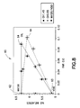
- FIG. 8 is a chart is shown comparing the Inelastic near:distant ratio (using Si, Ca, O, C and Fe as before) vs. C:O ratio.
- FIG. 9 is a chart is shown comparing the Inelastic near:far ratio vs. C:O ratio.
- spectral decomposition provide the ability to calculate ratios of inelastic gamma-rays which originate from a given element, such as silicon or calcium.
- a given element such as silicon or calcium.
- Gamma-rays that originate from these types of elements occur mostly in the formation and sample the neutron transport in the formation, rather than transport in the borehole, and are therefore more sensitive to the pore fluid density.
- the neutron transport was modeled with the Monte Carlo N-Particle (MCNP) transport code.
- MCNP Monte Carlo N-Particle
- a post processor for the MCNP output was used to identify inelastic gamma-rays by element for an RSTTM model and the near:far ratio of inelastic gamma-rays from silicon was calculated.
- the data points along line 2 are 100% liquid but with varying water saturation S w from 100% to 0% (S o consisting of CH2 varying from 0% to 100%).
- Data points along line 4 represent varying CH2 density but zero water saturation.
- Points along line 6 represent varying fractions of water and void.
- Points along dotted line 8 represent varying CH2 density (0, 0.2, 0.4 and 0.8 g/cm3) at 50% water saturation, except for one point that is CH4 at 0.2 g/cm3.
- Points along the line dotted 10 represent varying water saturation with CH2 hydrocarbon at 0.4 g/cm3.
- the CH4 calculation is compared to the CH2 calculation at the same hydrocarbon density, 0.2 g/cm3.
- the hydrogen density of the CH4 is 1.8 times as large at that in the CH2 calculation yet, within statistics, the near:far silicon ratio is the same for the two cases. This illustrates the insensitivity of near:far inelastic ratios to hydrogen.
- the C/H atomic ratio is proportional to the ratio of the pore hydrocarbon carbon density and the pore hydrocarbon hydrogen density:
- the pore hydrocarbon hydrogen density is proportional to the hydrogen index of the pore hydrocarbons:
- the hydrogen index (HI) is defined as the fraction of hydrogen in a given volume relative to that if the volume were filled with water.
- the neutron porosity which can be derived by several different logging instruments including the RSTTM, is an approximation to the HI of the entire formation, HI f .
- the HI of the pore hydrocarbons can be derived from HIf but it should be corrected for hydrogen in the matrix and pore water:
- HI hc HI f - ( 1 - ⁇ ) ⁇ HI m - ⁇ ⁇ ⁇ S w ⁇ ⁇ ( 1 - S w ) ( 3 )
- ⁇ is the true porosity.
- True porosity can be obtained from open hole data or from the RSTTM or similar techniques.
- the rock matrix hydrogen index, HI m can be calculated from capture spectroscopy data.
- the silicon near:far inelastic ratio has good sensitivity; approximately 30% change from 100% water to 100% void at 34 pu.
- the current RSTTM has a very large amount of fast epithermal capture background in the detectors (“tool background”) and, as a result, the fitted silicon yield has poor precision.
- tools background very large amount of fast epithermal capture background in the detectors
- gamma-rays from other elements can be added to those from silicon to form the near:far ratio. Precision could also be improved by using detectors with less epithermal capture background.
- Gamma-rays from any elements which have sensitivity to high energy neutron transport (even though it may be small) in the formation are acceptable, including calcium in carbonates, oxygen and iron.
- the near:far ratio of a combination of inelastic gamma-rays has been calculated in a format similar to FIG. 1 .
- the weight fraction of oxygen in just about any rock matrix is about 0.5, meaning that most of the oxygen signal comes from rock matrix and borehole water. Consequently, there is only a minor change in oxygen gamma-ray production even for 100% changes in water saturation. As it is used here, oxygen functions mainly as a normalization to the carbon yield.
- the bit size was 21.59 cm and the well was cased with 17.78 cm, 13.154 kilograms/30.48 cm casing.
- the water and oil points for bit size 21.59 cm and 17.78 cm 14.969 kilograms/30.48 cm casing were used. Near:far ratios for these are shown in FIG. 3 .
- the void point 20 was calculated by using a decreasing the water point by 16%, which is the sensitivity determined from Monte Carlo. As can be seen, most of the log points fall within the triangle, although a few fall outside which is expected due to statistical fluctuation. This triangle is calculated for 34 pu and, because a true porosity log was not available, all data points of the log are plotted on this triangle regardless of the actual porosity, which was in many cases less than 34 pu.
- the neutron/density “crossovers” 34 , 36 , 38 are shaded on the open hole log 32 .
- the crossovers 34 , 36 , 38 near ⁇ 917 m 34 , ⁇ 919 m, and ⁇ 938 m- ⁇ 940 m are indicators of low density, low hydrogen index pore fluid (“gas”).
- Low density fluid is indicated by simultaneously low water saturation and low hydrocarbon density on the RSTTM-derived plots.
- the entire zone at ⁇ 947- ⁇ 938 m has a classic water, oil and gas structure, with oil overriding the water and gas overriding the oil.
- the high water saturation at ⁇ 947 m and ending at ⁇ 944 m is echoed in the open hole resistivity.
- the bottom 5 m of this interval contain high density hydrocarbon (presumably liquid oil). Above this, the hydrocarbon density decreases, suggesting a progressively greater fraction of vapor compared to liquid.
- the vapor and liquid hydrocarbon saturations could be derived from the hydrocarbon density.
- pore hydrocarbon density, along with water saturation could be determined in an oil well from the near:far ratio of inelastic count rates and the ratio of carbon and oxygen count rates.
- the type of formation assumed in this model is one in which the hydrocarbon consists of both light and heavy molecular components, with the possibility that some of the light components form a vapor phase.
- the vapor and liquid hydrocarbon have a combined average density.
- lines parallel to the oil-void line 4 represent lines of different water saturation. Lines originating at the water point 12 and fanning out to the oil-void line 4 represent lines of different average hydrocarbon density.
- PVT Pressure-Volume-Temperature
- Lines 42 parallel to the oil-water line 40 now represent different steam saturations.
- Lines 44 , 46 , 48 , 50 , 52 originating at the 100% steam point and fanning out toward the oil-water line 40 represent lines of different oil and water fractions of the liquid. Water, oil and steam fractions can be calculated for any point within the triangle from the proportionate distance along these lines.
- the triangle plot of a well log in a steam flooded formation is shown in FIG. 6 .
- Another application is the gas-filled borehole.
- many 14 MeV neutrons from the source collide with either hydrogen or oxygen (carbon for an oil-filled borehole) in the borehole, having the effect of reducing the travel length of the neutrons.
- the neutrons In a gas-filled borehole, the neutrons rarely collide with nuclei in the low density gas and, consequently, the neutrons travel a longer distance than in the liquid-filled case.
- the effect in the gas-filled case is to make the high energy neutron cloud larger and more diffuse than in the liquid-filled case.
- the neutron population close to each detector is more heavily dominated by borehole transport (which is not sensitive to formation properties) than by transport through the formation.
- the neutron cloud is very large, much bigger than the spacing of the near and far detectors, and the neutrons reaching the neighborhood of each detector have predominantly traveled through the borehole; consequently the detectors sense essentially the same gamma-ray flux.
- the sensitivity of the near:far ratio to changes in pore fluid density is then very small. For conventional borehole sizes, the near:far ratio for a gas-filled borehole will have some sensitivity to pore fluid density but not as much as for a liquid-filled borehole.
- the spacing between near and far detectors can be increased. It is noted that increasing the detector spacing can reduce the statistical precision of the measurement. Ideally, the spacing between the near and far detectors should be maximized for the acceptable (predetermined) statistical precision for the measurement. This will depend on the nature of the detectors used, the measurement made, and the borehole environment as well as the user's tolerance to error.
- the new, larger, far detector spacing will be referred to as “distant” (or “d”) to distinguish it from the standard far detector spacing.
- disant or “d” to distinguish it from the standard far detector spacing.
- the modeled inelastic near far count rate ratios were used as before (cf FIG. 1 above) and plotted against far C:O ratio. Note that the C:O ratio can be measured at any detector, since both elements in this example are measured at the same location and therefore transport effects are eliminated. Choice of detector for this parameter might be determined by statistical precision (depends on neutron flux) and detector performance properties.
- FIG. 8 shows the plot 60 obtained using the new “distant” detector spacing.
- the plot forms a “response triangle” with water 62 , void 63 and oil 64 at the vertices, and intermediate locations for oil/water and various oil/gas mixtures.
- different oil compositions appear slightly displaced from each other, so that the response triangles for CH0.55 and CH1.45 do not overlay each other.
- FIG. 9 shows the same plot using the standard far detector spacing instead of the longer-spaced “distant” detector.
- the contrast between water (density 1.0 g/cc) and void (density 0) is dramatically reduced (the water/void contrast drops from approximately 25% to approximately 10%). This is particularly noticeable in the size of the statistical error bars from the Monte Carlo simulation, which are small for the distant detector plot but comparatively much larger when using the standard far detector, despite better simulation statistics for the far detector.
- hydrocarbon composition e.g. CH0.55 and CH1.45
- hydrocarbon composition e.g. CH0.55 and CH1.45
- This dependence could be eliminated by using a correction based on the hydrogen fraction, or hydrogen index HI.
- neutron transport effects are eliminated to obtain a normalized local elemental abundance by using a local ratio, it might be thought that a H:Si ratio would provide a normalized hydrogen yield.
- hydrogen does not yield inelastic gamma rays
- the hydrogen and silicon capture yields are both available and have been used to determine a H:Si ratio, shown in FIG. 4 below.
- the different composition hydrocarbons both match the same curve, the response is double valued with a minimum for a HI of approximately 0.06. Therefore the H:Si capture ratio does not provide the necessary HI determination to correct the inelastic ratios.
- thermal neutron near:far ratio An alternative method to determine the hydrogen content of the formation (including pore fluids) is to use a thermal neutron near:far ratio. This is commonly measured in neutron logs, which may use thermal (or epithermal) neutron detectors. In the present case, which uses a tool with gamma-ray detectors and a pulsed neutron generator, the thermal neutron rate can be determined by measuring the yield of capture gamma-rays at times when the generator is off.
- the capture near:far ratio reflects the formation hydrogen index, as shown by the calculated data plotted in FIG. 5 . Not only is this parameter a single-valued function of HI, but the different composition hydrocarbons fall on approximately the same line (within statistical errors).
- the capture near:far ratio can be measured at different distances, so that either a standard far detector spacing or a longer “distant” detector spacing can be used, as confirmed by modeling studies.
- the inelastic ratio data of FIG. 2 can now be corrected for hydrogen content by subtracting the capture near:far or near:distant ratio, multiplied by a suitable coefficient. This is done in FIG. 6 , which shows the near:distant inelastic ratio corrected using a coefficient of 0.35. For comparison, the corresponding plot using standard far detector spacing is shown in FIG. 7 ; it is clear that, with the dramatically reduced contrast using standard far detector spacing, extremely high measurement precision would be preferred. This difficulty is resolved by using a longer-spaced detector, which results in better density contrast.
Abstract
Description
where r is the distance from the neutron source, and the inelastic gamma-ray production will have, approximately, this spatial dependence. Since the detection probability is high when the gamma-rays are produced close to the detector, the detection rate for detectors at distances rn and rf from the neutron source (where rn is the distance to the near detector and rf is the distance to the far detector) will be modulated by
respectively. (1 MeV is approximately the lowest energy at which inelastic scattering is possible.) The ratio of detection rates will then vary as
For a small slowing down length increase ΔLh, the ratio of detection rates decreases at a rate proportional to ΔLh/Lh 2. Since Lh varies little with (liquid filled) porosity, it is expected that the near:far inelastic gamma-ray ratio would also have little dependence on porosity. Note that this also implies that the near:far inelastic ratio would have no direct dependence on bulk formation density, since this varies with porosity. Of course, if the density of inelastic scatterers were to vary, then Lh and the near:far inelastic ratio would also vary. But this typically does not happen unless the lithology changes, such as from a sandstone to a shale.
The hydrogen index (HI) is defined as the fraction of hydrogen in a given volume relative to that if the volume were filled with water. The neutron porosity, which can be derived by several different logging instruments including the RST™, is an approximation to the HI of the entire formation, HIf. The HI of the pore hydrocarbons can be derived from HIf but it should be corrected for hydrogen in the matrix and pore water:
where φ is the true porosity. True porosity can be obtained from open hole data or from the RST™ or similar techniques. The rock matrix hydrogen index, HIm, can be calculated from capture spectroscopy data.
Claims (7)
Priority Applications (1)
| Application Number | Priority Date | Filing Date | Title |
|---|---|---|---|
| US11/781,404 US7791017B2 (en) | 2007-07-23 | 2007-07-23 | Method to simultaneously determine pore hydrocarbon density and water saturation from pulsed neutron measurements |
Applications Claiming Priority (1)
| Application Number | Priority Date | Filing Date | Title |
|---|---|---|---|
| US11/781,404 US7791017B2 (en) | 2007-07-23 | 2007-07-23 | Method to simultaneously determine pore hydrocarbon density and water saturation from pulsed neutron measurements |
Publications (2)
| Publication Number | Publication Date |
|---|---|
| US20090026359A1 US20090026359A1 (en) | 2009-01-29 |
| US7791017B2 true US7791017B2 (en) | 2010-09-07 |
Family
ID=40294410
Family Applications (1)
| Application Number | Title | Priority Date | Filing Date |
|---|---|---|---|
| US11/781,404 Active US7791017B2 (en) | 2007-07-23 | 2007-07-23 | Method to simultaneously determine pore hydrocarbon density and water saturation from pulsed neutron measurements |
Country Status (1)
| Country | Link |
|---|---|
| US (1) | US7791017B2 (en) |
Cited By (5)
| Publication number | Priority date | Publication date | Assignee | Title |
|---|---|---|---|---|
| US20110180697A1 (en) * | 2010-01-28 | 2011-07-28 | Baker Hughes Incorporated | Time dependent measurement of formation properties using pulsed neutron generators |
| US20110191030A1 (en) * | 2010-02-01 | 2011-08-04 | Baker Hughes Incorporated | Apparatus and algorithm for measuring formation bulk density |
| US20110198489A1 (en) * | 2010-02-01 | 2011-08-18 | Baker Hughes Incorporated | Lithology pair ratio: a ratio-based lithology indicator using pair production |
| US20190025454A1 (en) * | 2016-09-26 | 2019-01-24 | Halliburton Energy Services, Inc. | Neutron porosity log casing thickness corrections |
| US10208582B2 (en) | 2016-08-24 | 2019-02-19 | Saudi Arabian Oil Company | Formation water salinity from borehole measurements |
Families Citing this family (23)
| Publication number | Priority date | Publication date | Assignee | Title |
|---|---|---|---|---|
| US20100200395A1 (en) * | 2009-02-06 | 2010-08-12 | Anton Dietrich | Techniques for depositing transparent conductive oxide coatings using dual C-MAG sputter apparatuses |
| WO2010096802A2 (en) * | 2009-02-23 | 2010-08-26 | Baker Hughes Incorporated | Method for accentuating signal from ahead of the bit |
| GB2481159B (en) * | 2009-04-07 | 2013-06-19 | Baker Hughes Inc | Gamma ray generator |
| GB2481158B (en) * | 2009-04-07 | 2013-05-29 | Baker Hughes Inc | Method for taking gamma-gamma density measurements |
| EP2241906B1 (en) | 2009-04-17 | 2015-04-01 | Services Pétroliers Schlumberger | Method of determining density of underground formations using neutron-gamma ray measurements |
| US9897719B2 (en) * | 2009-05-22 | 2018-02-20 | Schlumberger Technology Corporation | Optimization of neutron-gamma tools for inelastic-gamma ray logging |
| US9229125B2 (en) * | 2009-09-17 | 2016-01-05 | Baker Hughes Incorporated | TDEM forward focusing system for downhole use |
| US9086500B2 (en) | 2010-01-08 | 2015-07-21 | Baker Hughes Incorporated | Apparatus and method for pulsed neutron measurement |
| GB2491294B (en) * | 2010-03-05 | 2015-05-20 | Baker Hughes Inc | Apparatus and method for measuring downhole fluid composition and properties |
| US8502135B2 (en) * | 2010-03-25 | 2013-08-06 | Baker Hughes Incorporated | Method for through-casing 3-phase saturation determination |
| EP2596386A4 (en) * | 2010-08-26 | 2017-09-13 | Smith International, Inc. | Method for measuring subterranean formation density using a neutron generator |
| EP2972519A4 (en) * | 2010-12-17 | 2017-01-18 | Services Pétroliers Schlumberger | Gas detection and quantification method using a pulsed neutron logging tool |
| US10385677B2 (en) | 2012-04-05 | 2019-08-20 | Schlumberger Technology Corporation | Formation volumetric evaluation using normalized differential data |
| US20130268201A1 (en) * | 2012-04-05 | 2013-10-10 | Schlumberger Technology Corporation | Formation compositional evaluation using normalized differential data |
| MX337895B (en) | 2012-04-19 | 2016-03-23 | Halliburton Energy Services Inc | System and method of determining a value indicative of hydrogen index. |
| EP2839317A4 (en) | 2012-04-19 | 2015-09-30 | Halliburton Energy Services Inc | System and method of determining a value indicative of hydrogen index |
| CA2875764A1 (en) * | 2012-06-06 | 2013-12-12 | Halliburton Energy Services, Inc. | Method and system of resin evaluation using pulsed neutron tools |
| US9389335B2 (en) * | 2013-05-17 | 2016-07-12 | Halliburton Energy Services, Inc. | Pulsed neutron tool for downhole oil typing |
| US9885802B2 (en) * | 2013-10-01 | 2018-02-06 | Baker Hughes, A Ge Company, Llc | Downhole cement evalution using pulsed neutron measurements |
| CN112649855B (en) * | 2019-10-11 | 2024-04-09 | 中国石油化工股份有限公司 | Three-dimensional gas saturation prediction method and system |
| US11204439B2 (en) * | 2020-04-29 | 2021-12-21 | Halliburton Energy Services, Inc. | Porosity determination using optimization of inelastic and capture count rates in downhole logging |
| CN112814667B (en) * | 2021-01-05 | 2023-07-14 | 中海石油(中国)有限公司 | Method for evaluating water content of tight gas layer based on thermal neutron logging count rate ratio |
| US11681069B1 (en) * | 2022-01-03 | 2023-06-20 | Halliburton Energy Services, Inc. | Pulsed neutron tool for elemental decay logging |
Citations (10)
| Publication number | Priority date | Publication date | Assignee | Title |
|---|---|---|---|---|
| US4577102A (en) * | 1981-12-09 | 1986-03-18 | Schlumberger Technology Corporation | Method and apparatus for distinguishing hydrocarbon from fresh water in situ |
| US5055676A (en) * | 1990-05-09 | 1991-10-08 | Schlumberger Technology Corporation | Method for determining oil and water saturation in earth formation surrounding a borehole |
| US5259239A (en) * | 1992-04-10 | 1993-11-09 | Scott Gaisford | Hydrocarbon mass flow meter |
| US5532482A (en) | 1994-04-12 | 1996-07-02 | Schlumberger Technology Corporation | Method and apparatus for well logging using an accelerator neutron source |
| US5900627A (en) * | 1997-06-19 | 1999-05-04 | Computalog Research, Inc. | Formation density measurement utilizing pulse neutrons |
| US6732796B2 (en) | 2000-04-24 | 2004-05-11 | Shell Oil Company | In situ production of synthesis gas from a hydrocarbon containing formation, the synthesis gas having a selected H2 to CO ratio |
| US20040248314A1 (en) | 2003-06-04 | 2004-12-09 | Schlumberger Technology Corporation | Flow meter interpretation |
| US7117092B2 (en) * | 2003-09-25 | 2006-10-03 | Halliburton Energy Services, Inc. | Pulsed-neutron formation density |
| US20070143021A1 (en) * | 2005-12-06 | 2007-06-21 | Schlumberger Technology Corporation | Determination of Porosity and Fluid Saturation of Underground Formations |
| US7587373B2 (en) * | 2005-06-24 | 2009-09-08 | Halliburton Energy Services, Inc. | Neural network based well log synthesis with reduced usage of radioisotopic sources |
Family Cites Families (1)
| Publication number | Priority date | Publication date | Assignee | Title |
|---|---|---|---|---|
| US5805195A (en) * | 1996-03-26 | 1998-09-08 | Oyo Instruments, Inc. | Diode-less thermal print head and method of controlling same |
-
2007
- 2007-07-23 US US11/781,404 patent/US7791017B2/en active Active
Patent Citations (13)
| Publication number | Priority date | Publication date | Assignee | Title |
|---|---|---|---|---|
| US4577102A (en) * | 1981-12-09 | 1986-03-18 | Schlumberger Technology Corporation | Method and apparatus for distinguishing hydrocarbon from fresh water in situ |
| US5055676A (en) * | 1990-05-09 | 1991-10-08 | Schlumberger Technology Corporation | Method for determining oil and water saturation in earth formation surrounding a borehole |
| US5259239A (en) * | 1992-04-10 | 1993-11-09 | Scott Gaisford | Hydrocarbon mass flow meter |
| US5532482A (en) | 1994-04-12 | 1996-07-02 | Schlumberger Technology Corporation | Method and apparatus for well logging using an accelerator neutron source |
| US5900627A (en) * | 1997-06-19 | 1999-05-04 | Computalog Research, Inc. | Formation density measurement utilizing pulse neutrons |
| US6761216B2 (en) | 2000-04-24 | 2004-07-13 | Shell Oil Company | In situ thermal processing of a coal formation to produce hydrocarbon fluids and synthesis gas |
| US6732796B2 (en) | 2000-04-24 | 2004-05-11 | Shell Oil Company | In situ production of synthesis gas from a hydrocarbon containing formation, the synthesis gas having a selected H2 to CO ratio |
| US6769485B2 (en) | 2000-04-24 | 2004-08-03 | Shell Oil Company | In situ production of synthesis gas from a coal formation through a heat source wellbore |
| US6805195B2 (en) | 2000-04-24 | 2004-10-19 | Shell Oil Company | In situ thermal processing of a hydrocarbon containing formation to produce hydrocarbon fluids and synthesis gas |
| US20040248314A1 (en) | 2003-06-04 | 2004-12-09 | Schlumberger Technology Corporation | Flow meter interpretation |
| US7117092B2 (en) * | 2003-09-25 | 2006-10-03 | Halliburton Energy Services, Inc. | Pulsed-neutron formation density |
| US7587373B2 (en) * | 2005-06-24 | 2009-09-08 | Halliburton Energy Services, Inc. | Neural network based well log synthesis with reduced usage of radioisotopic sources |
| US20070143021A1 (en) * | 2005-12-06 | 2007-06-21 | Schlumberger Technology Corporation | Determination of Porosity and Fluid Saturation of Underground Formations |
Non-Patent Citations (10)
| Title |
|---|
| Hakes, Long Term World Oil Supply, Energy Information Administration, 2000, http://tonto.eia.doe.gov/FTPROOT/ petroleum/LongTermOilSupplyPresentation.ppt, retrieved Jun. 11, 2008, Slides 1-20. |
| Herron et al., Application of Nuclear Spectroscopy Logs to the Derivation of Formation Matrix Density, Paper JJ Presented at the 41st Annual Logging Symposium of the Society of Professional Well Log Analysts, Jun. 4-7, 2000, Dallas, Texas, pp. 1-12. |
| Herron et al., Log Interpretation Parameters Determined from Chemistry, Mineralogy and Nuclear Forward Modeling, Proceedings 1997 International Symposium of the Society of Core Analysts, Sep. 8-10, Calgary Paper SCA-9727, pp. 1-14. |
| Herron et al., Real-Time Petrophysical Analysis in Siliciclastics From the Integration of Spectroscopy and Triple-Combo Logging, SPE 77631, 2002, pp. 1-7. |
| Morris et al., Differentiation of Gas in Sand/Shale Environments Using Pulsed Neutron Capture Measurements, SPE 38703, 1997, pp. 511-523. |
| Odom et al, Log Examples with a Prototype Three-Detector Pulsed-Neutron System for Measurement of Cased-Hole Neutron and Density Porosities, SPE 71042, 2001, pp. 1-10. |
| Odom et al., Applications and Derivation of a New Cased-hole Density Porosity in Shaly Sands, SPE 38699, 1997, pp. 475-487. |
| Odom et al., Improvements in a Through-Casing Pulsed-Neutron Density Log, SPE 71742, 2001, pp. 1-9. |
| Stephenson, High Pressure 4HE Proportional Counters as Borehole Detectors of MEV Neutrons, IEEE, 1995, pp. 802-806. |
| Webster et al., Multiphase Well Surveillance with a Permanent Downhole Flowmeter, SPE 90024, 2004, pp. 1-8. |
Cited By (11)
| Publication number | Priority date | Publication date | Assignee | Title |
|---|---|---|---|---|
| US20110180697A1 (en) * | 2010-01-28 | 2011-07-28 | Baker Hughes Incorporated | Time dependent measurement of formation properties using pulsed neutron generators |
| US20110213555A1 (en) * | 2010-01-28 | 2011-09-01 | Baker Hughes Incorporated | Time dependent neutron-gamma spectroscopy |
| US8853618B2 (en) | 2010-01-28 | 2014-10-07 | Baker Hughes Incorporated | Time dependent measurement of formation properties using pulsed neutron generators |
| US9766368B2 (en) | 2010-01-28 | 2017-09-19 | Baker Hughes Incorporated | Time dependent neutron-gamma spectroscopy |
| US20110191030A1 (en) * | 2010-02-01 | 2011-08-04 | Baker Hughes Incorporated | Apparatus and algorithm for measuring formation bulk density |
| US20110198489A1 (en) * | 2010-02-01 | 2011-08-18 | Baker Hughes Incorporated | Lithology pair ratio: a ratio-based lithology indicator using pair production |
| US8700333B2 (en) | 2010-02-01 | 2014-04-15 | Baker Hughes Incorporated | Apparatus and algorithm for measuring formation bulk density |
| US9658361B2 (en) | 2010-02-01 | 2017-05-23 | Baker Hughes Incorporated | Lithology pair ratio: a ratio-based lithology indicator using pair production |
| US10208582B2 (en) | 2016-08-24 | 2019-02-19 | Saudi Arabian Oil Company | Formation water salinity from borehole measurements |
| US20190025454A1 (en) * | 2016-09-26 | 2019-01-24 | Halliburton Energy Services, Inc. | Neutron porosity log casing thickness corrections |
| US10451767B2 (en) * | 2016-09-26 | 2019-10-22 | Halliburton Energy Services, Inc. | Neutron porosity log casing thickness corrections |
Also Published As
| Publication number | Publication date |
|---|---|
| US20090026359A1 (en) | 2009-01-29 |
Similar Documents
| Publication | Publication Date | Title |
|---|---|---|
| US7791017B2 (en) | Method to simultaneously determine pore hydrocarbon density and water saturation from pulsed neutron measurements | |
| US9851468B2 (en) | Hydrocarbon saturation from total organic carbon logs derived from inelastic and capture nuclear spectroscopy | |
| Hertzog et al. | Geochemical logging with spectrometry tools | |
| US7366615B2 (en) | Methods and apparatus using both nuclear capture and inelastic spectroscopy in deriving elemental concentrations | |
| US7623968B2 (en) | Determination of porosity and fluid saturation of underground formations | |
| Lecompte et al. | Quantifying source rock maturity from logs: how to get more than TOC from delta log R | |
| US8884216B2 (en) | Gas detection and quantification method using a pulsed neutron logging tool | |
| CN102012526A (en) | Method for discriminating type of reservoir fluid by using resistivity data | |
| Guo et al. | A new three-detector 1-11/16-inch pulsed neutron tool for unconventional reservoirs | |
| AU2010237344B2 (en) | Method of determining density of underground formations using neutron-gamma ray measurements | |
| US7112783B2 (en) | Neutron measurement method for determining porosity of a formation surrounding a borehole | |
| Lock et al. | Carbon-oxygen (C/O) log: Use and interpretation | |
| Roscoe et al. | Response of the carbon/oxygen measurement for an inelastic gamma ray spectroscopy tool | |
| Miles et al. | Formation chlorine measurement from spectroscopy enables water salinity interpretation: Theory, modeling, and applications | |
| Ellis | Neutron porosity devices-what do they measure? | |
| Schweitzer et al. | Gamma ray spectroscopy tool: environmental effects | |
| Neville et al. | A new-generation LWD tool with colocated sensors opens new opportunities for formation evaluation | |
| Serry et al. | Fluid-front tracking in a mature jurassic carbonate reservoir using innovative pulsed neutron solutions for the first time offshore Abu Dhabi | |
| Kerr et al. | The evaluation of oil saturation through casing using carbon/oxygen logs | |
| Schweitzer et al. | Review of nuclear techniques in subsurface geology | |
| Ma et al. | Intrinsic Carbon-Oxygen Logging for Enhanced Consistency of Reservoir Saturation Monitoring | |
| Guoxin et al. | Petrophysical characterization of a complex volcanic reservoir | |
| Ullo et al. | Effects of Invasion on the Compensated Neutron Log (CNL) in Gas and Liquid-Filled Formations | |
| Cannon et al. | Through-casing reservoir evaluation | |
| Neville et al. | Integrated interpretation of a rich data set from a new-generation LWD tool |
Legal Events
| Date | Code | Title | Description |
|---|---|---|---|
| AS | Assignment |
Owner name: SCHLUMBERGER TECHNOLOGY CORPORATION, MASSACHUSETTS Free format text: ASSIGNMENT OF ASSIGNORS INTEREST;ASSIGNORS:STEPHENSON, KENNETH E.;FITZGERALD, JOHN BARRY;REEL/FRAME:019982/0190;SIGNING DATES FROM 20070813 TO 20070823 Owner name: SCHLUMBERGER TECHNOLOGY CORPORATION, MASSACHUSETTS Free format text: ASSIGNMENT OF ASSIGNORS INTEREST;ASSIGNORS:STEPHENSON, KENNETH E.;FITZGERALD, JOHN BARRY;SIGNING DATES FROM 20070813 TO 20070823;REEL/FRAME:019982/0190 |
|
| STCF | Information on status: patent grant |
Free format text: PATENTED CASE |
|
| FPAY | Fee payment |
Year of fee payment: 4 |
|
| MAFP | Maintenance fee payment |
Free format text: PAYMENT OF MAINTENANCE FEE, 8TH YEAR, LARGE ENTITY (ORIGINAL EVENT CODE: M1552) Year of fee payment: 8 |
|
| MAFP | Maintenance fee payment |
Free format text: PAYMENT OF MAINTENANCE FEE, 12TH YEAR, LARGE ENTITY (ORIGINAL EVENT CODE: M1553); ENTITY STATUS OF PATENT OWNER: LARGE ENTITY Year of fee payment: 12 |