US7791655B2 - Imaging apparatus with function of shading compensation - Google Patents
Imaging apparatus with function of shading compensation Download PDFInfo
- Publication number
- US7791655B2 US7791655B2 US11/899,376 US89937607A US7791655B2 US 7791655 B2 US7791655 B2 US 7791655B2 US 89937607 A US89937607 A US 89937607A US 7791655 B2 US7791655 B2 US 7791655B2
- Authority
- US
- United States
- Prior art keywords
- limb
- darkening
- image
- unit
- brightness
- Prior art date
- Legal status (The legal status is an assumption and is not a legal conclusion. Google has not performed a legal analysis and makes no representation as to the accuracy of the status listed.)
- Expired - Fee Related, expires
Links
Images


Classifications
-
- H—ELECTRICITY
- H04—ELECTRIC COMMUNICATION TECHNIQUE
- H04N—PICTORIAL COMMUNICATION, e.g. TELEVISION
- H04N23/00—Cameras or camera modules comprising electronic image sensors; Control thereof
- H04N23/60—Control of cameras or camera modules
-
- H—ELECTRICITY
- H04—ELECTRIC COMMUNICATION TECHNIQUE
- H04N—PICTORIAL COMMUNICATION, e.g. TELEVISION
- H04N23/00—Cameras or camera modules comprising electronic image sensors; Control thereof
- H04N23/95—Computational photography systems, e.g. light-field imaging systems
- H04N23/951—Computational photography systems, e.g. light-field imaging systems by using two or more images to influence resolution, frame rate or aspect ratio
-
- H—ELECTRICITY
- H04—ELECTRIC COMMUNICATION TECHNIQUE
- H04N—PICTORIAL COMMUNICATION, e.g. TELEVISION
- H04N25/00—Circuitry of solid-state image sensors [SSIS]; Control thereof
- H04N25/60—Noise processing, e.g. detecting, correcting, reducing or removing noise
- H04N25/61—Noise processing, e.g. detecting, correcting, reducing or removing noise the noise originating only from the lens unit, e.g. flare, shading, vignetting or "cos4"
Definitions
- the present invention relates to an imaging apparatus, a method of shooting an object and a computer program product, and more specifically, to an image apparatus, a method of shooting an object and a computer program product, which are used suitably, for instance, in digital cameras and the like for obtaining photographs having good image quality even when shooting with a long exposure time.
- FIG. 12 is a view showing a general idea of the a first conventional technique disclosed in Japanese Patent Application 2001-326850A.
- T 1 denotes an exposure time for shooting an object under low light conditions where it is prohibited to use a strobe light.
- the exposure time T 1 is an exposure time that is longer than an appropriate time for shooting under good light conditions.
- an image signal is read out from the two-dimensional image sensor several times during the exposure time T 1 .
- the exposure time T 1 is evenly divided into four exposure times, T 1 (1) to T 1 (4) , as shown in FIG. 12 , and images are read out from the image sensor respectively in four exposure times T 1 (1) to T 1 (4) .
- the exposure time T 1 is not always divided evenly but may be simply divided into plural exposure times.
- these four images 1 to 4 are combined together to produce one image signal 5 .
- sizes of four images 1 to 4 are different from the combined image 5 , but the image 5 is drawn larger than other images 1 to 4 for the sake of explanation. In practice, the four images 1 to 4 have the same size as the combine image 5 .
- the exposure time (T 1 (1) to T 1 (4) ) for each of the images 1 to 4 is obtained by dividing the exposure time T 1 by 4, where the exposure time T 1 is an exposure time for shooting an object under low light conditions where it is prohibited to use the strobe light. Therefore, when the exposure time (T 1 (1) to T 1 (4) ) for the images 1 to 4 is obtained by dividing the exposure time T 1 evenly, brightness of the images 1 to 4 would have been one fourth of target brightness.
- brightness of the image 5 obtained by combining these four images 1 to 4 corresponds to approximately four times of brightness of each of the images 1 to 4 .
- an image (combined image 5 ) can be obtained, of a predetermined brightness corresponding to the exposure time for shooting an object under low light conditions where it is prohibited to use the strobe light.
- a dark current component (a level of which is assumed to be “P” for convenience) contained in the combined image 5 corresponds approximately to the total ( ⁇ P (1) +P (2) +P (3) +P (4) ) of dark current components (levels of which are assumed to be P (1) , P (2) , P (3) and P (4) respectively for convenience) contained in each of the images 1 to 4 .
- the dark current is a sort of sensor noises that increase exponentially with exposure time.
- the first conventional technique mentioned above has advantages in improving image quality of an image photographed with a long exposure time. But on the contrary the first conventional technique has disadvantages that cannot solve problems caused due to camera shake, which occurs frequently.
- Japanese Patent Application 2005-182089 A describes a technique (hereinafter, a “second conventional technique”) which takes measures for camera shake.
- FIGS. 13A and 13B are views illustrating an idea of the second conventional technique.
- FIG. 13A four images 6 to 9 correspond respectively to the images 1 to 4 obtained in the first conventional technique as shown in FIG. 12 .
- an image 10 corresponds to the combined image 5 in the first conventional technique as shown in FIG. 12 .
- the second conventional technique is different from the first conventional technique in that objects (persons) of four images 6 to 9 are shifted in position a little from each other in the images. More specifically, when compared with the position of the person 11 in the first image 6 , the person 12 of the second image 7 is shifted in position a little to the right by an amount of F 1 as shown in the image 7 of FIG. 13A .
- the person 13 of the third image 8 is shifted in position a little to the right by an amount of F 2 as shown in the image 8 of FIG. 13A .
- the person 14 of the fourth image 9 is shifted in position a little to the right by an amount of F 3 as shown in the image 9 of FIG. 13A .
- the persons 11 to 14 appearing in the four images 6 to 9 are the same person, and therefore these four images indicate that the camera are shaken in the leftward while these images are photographed.
- the second conventional technique has been described with respect to the camera which has been shaken in the horizontal direction.
- the second technique can be applied to the camera which has been shaken not only in the horizontal direction but also in the vertical direction or in the other direction.
- Plural feature points common to these images 6 to 9 are calculated to determine their relative positions, and relative positions of the images 6 to 9 are determined based on the determined relative positions of the feature points. Then, positions of the four images 6 to 9 are corrected based on the determined relative positions of the four images 6 to 9 to combine the four images together, thereby generating one combined image 10 . In short, movement or displacement between two images which are adjacent in terms of time is detected and then the detected movement or displacement is corrected to generate the combined image 10 .
- the second conventional technique solves problems caused due to camera shake by correcting the movement or displacement between images adjacent in terms of time.
- the second conventional technique has another disadvantages that it takes a long time to compensate for limb darkening of an optical system, as described below.
- FIG. 14 is a view illustrating limb darkening phenomenon of the optical system.
- the bold circle outermost among a number of concentric circles denotes an image circle 15 of the optical system.
- a landscape rectangle within the image circle 15 denotes an imaging area 16 of the two-dimensional image sensor such as CCD.
- An image 18 shown below the image circle 15 in FIG. 14 represents an image output from the two-dimensional image sensor, which includes an image of a person-like object in the vicinity of the center of the imaging area 16 .
- an optical system of a camera brightness at a point on an image is determined depending on characteristics of the optical lens and has “limb darkening characteristics”. That is, the brightness at a point on an image is given by cos 4 ⁇ , where ⁇ denotes an angle between a line connecting the point on the image with an optical lens and an optical axis of the optical lens.
- ⁇ denotes an angle between a line connecting the point on the image with an optical lens and an optical axis of the optical lens.
- a number of concentric circles arranged within the image circle 15 schematically indicate the limb-darkening characteristics. A closer space between the circles expresses that darkening rate is larger.
- the limb darkening is accepted to some extent, but most cameras employ a sort of image processing for compensating for the limb darkening.
- Japanese Patent Application 2002-296685 A describes a technique (hereinafter, a “third conventional technique”) that increases brightness at a point on the image 18 shown in FIG. 14 as the point moves to edge of the image, thereby solving the problem of limb darkening without increasing costs.
- the limb darkening effect appears in the original image 18 as illustrated by spaces between concentric circles shown within the image 18 .
- the third conventional technique uses such proper compensation data as cancels the limb darkening effect in the image 18 to make brightness distribution even and/or flat over the image 18 .
- the third conventional technique (a method of processing an image to compensate for limb darkening in the image) is applied to the second conventional technique without any modification made to said third conventional technique, it is hard to make brightness distribution flat or even over the finally obtained image 10 which is subjected to limb darkening effect.
- FIG. 15 is a view illustrating disadvantages caused by the conventional techniques.
- FIG. 15 a process is shown, for simplicity, in which two images (first image 19 and second image 20 ) which have been photographed continuously are combined together to generate one combined image 21 .
- a person 22 appears approximately at the center of the first image 19
- the same person 23 appears at a position shifted slightly in a lower rightward direction from the position of the person 22 in the first image 19 . That is, camera shake makes the position of the person 23 in the second image 20 shift from the position of the person 22 in the first image 19 .
- the combined image 21 is obtained with a person 24 appearing approximately at the center thereof.
- Blacked out portions of the first image 19 and the second image 20 in FIG. 15 schematically represent a portion 25 of low brightness in the first image 19 and a portion 26 of low brightness in the second image 20 , respectively. These portions of low brightness are yielded due to limb-darkening characteristics of the optical system of the camera.
- portions of low brightness included in the combined image consist of the low-brightness portion 25 of the first image 19 , low-brightness portion 26 of the second image 20 , and a superimposed portion (medium-brightness portion) 27 of the two low-brightness portions 25 and 26 .
- the combined image 21 includes not only low-brightness portions 25 , 26 but also the medium-brightness portion 27 , which is brighter than the low-brightness portions 25 , 26 . Therefore, when simple compensation is made to the combined image based on the limb-darkening characteristics of the optical system to as to compensate for low brightness in the combined image, the medium-brightness portion 27 would have been compensated for excessively.
- the compensation process described above is not practicable to make brightness distribution (low-brightness portions 25 , 26 and medium-brightness portion 27 ) due to the limb darkening even or flat in the finally obtained image.
- an imaging apparatus which comprises a photographing unit having an optical system for photographing an object through the optical system to generate an image of the object, a combining unit for correcting displacement of plural images of the same object generated by the photographing unit and for combining the plural images whose displacement has been corrected, thereby generating a combined image, and a limb-darkening compensating unit for compensating for limb darkening in the combined image generated by the combining unit based on limb-darkening characteristics of the optical system.
- a method of photographing an object which comprises photographing an object through an optical system to generate plural images of the object, correcting displacement of the plural images to combine said plural images, thereby generating a combined image, and compensating for limb darkening in the combined image based on limb-darkening characteristics of the optical system.
- a computer program product stored on a computer readable medium for controlling operation of a computer, the computer program product making the computer operate as means including means for photographing an object through an optical system to generate plural images of the object, means for correcting displacement of the plural images to combine said plural images, thereby generating a combined image, and means for compensating for limb darkening in the combined image based on limb-darkening characteristics of the optical system.
- FIG. 1 is a block diagram showing a configuration of a digital camera.
- FIG. 2A is a view schematically illustrating an idea of generating a brightness curve on the basis of consideration of camera shake.
- FIG. 2B is a view schematically illustrating an idea of generating a brightness curve on the basis of consideration of camera shake.
- FIG. 2C is a view schematically illustrating an idea of generating a brightness curve on the basis of consideration of camera shake.
- FIG. 3 is a view schematically illustrating an idea of a limb-darkening compensation process to be executed on a combined image.
- FIG. 4 is a view showing brightness curves which are generated based on limb darkening in images.
- FIG. 5 is a view showing brightness curves which are generated based on limb darkening in images.
- FIG. 6 is a view illustrating a brightness curve which indicates the maximum compensation coefficient at the field angle boundary at the time when the images are displaced to the maximum due to camera shake.
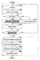
- FIG. 7 is a flow chart of operation performed in the first embodiment of the imaging apparatus of the invention.
- FIG. 8 is a view showing displacement between an optical lens and a light receiving unit.
- FIG. 9 is a flow chart of a process for making limb-darkening compensation on the basis of considerations of displacement between the optical lens and the light receiving unit.
- FIG. 10A is a view illustrating an idea of a digital zoom operation.
- FIG. 10B is a view illustrating the idea of a digital zoom operation.
- FIG. 10C is a view illustrating the idea of a digital zoom operation.
- FIG. 11 is a flow chart of a limb-darkening compensation process in a digital zoom mode.
- FIG. 12 is a view showing a general idea of a first conventional technique.
- FIG. 13A is a view showing a general idea of a second conventional technique.
- FIG. 13B is a view showing the general idea of the second conventional technique.
- FIG. 14 is a view illustrating limb darkening of an optical system.
- FIG. 15 is a view illustrating disadvantages of the conventional technique.
- FIG. 16A is a view illustrating displacement of a second image to explain an average displacement.
- FIG. 16B is a view illustrating displacement of a third image to explain an average displacement.
- FIG. 16C is a view illustrating displacement of a fourth image to explain an average displacement.
- FIG. 16D is a view illustrating an average displacement.
- FIG. 17 is a view illustrating allowances and allowable ranges of displacement between an optical lens and a light receiving unit.
- FIG. 18 is a view illustrating measurement of allowances of displacement between the optical lens and the light receiving unit.
- FIG. 1 is a block diagram showing a configuration of a digital camera.
- the digital camera 30 comprises an image pick-up unit 31 , image processing unit 32 , memory unit 33 , video output unit 34 , display unit 35 , control unit 36 , program code storage unit 37 , operation unit 38 , external interface unit 39 , image storage unit 40 and power source unit 41 .
- the image pick-up unit 31 has an optical system 31 a and a two-dimensional image sensor 31 b .
- the optical system 31 a includes a photographic lens which comprises a single lens or an assembly of plural lenses, aperture adjustment mechanism, focus adjustment mechanism, and a zoom mechanism for adjusting an angle “ ⁇ ” of view (or focal length).
- the two-dimensional image sensor 31 b consists of a semi-conductor device such as CCD sensor and CMOS sensor.
- Operation of the image pick-up unit 21 is controlled in accordance with instructions of photographing operation sent from the control unit 36 .
- the operation of the image pick-up unit 21 includes adjustment of aperture and zoom ratio, that is, adjustment of view angle “ ⁇ ”, focus adjustment, and adjustment of exposure or amount of light allowed to fall on the two-dimensional image sensor 31 b , and operation of reading an image.
- the instructions of photographing operation sent from the control unit 36 include an instruction of reading an image of an object 30 a of a low resolution (for example, XGA image of 1024 ⁇ 768 dots) at a high frame rate (for example, 30 fps), an instruction of reading an image of the object 30 a of a high resolution (for example, image of 400 mega dots) at a low frame rate (for example, a frame rate a little lower than the above high frame rate of 30 fps), and an instruction of previously setting aperture, focusing operation and a zoom ratio which are required for reading the image.
- the image of a low resolution is prepared for a user to determine or confirm a composition of a photograph
- the image of a high resolution is prepared for taking a still photograph.
- the object image (hereinafter, a “through image”) of the object 30 a of a low resolution is periodically read from the image pick-up unit 31 at the high frame rate for confirming the composition of a photograph.
- the through image is transferred from an image buffer area 33 a of the memory unit 33 to a display image area 33 c , and further to the video output unit 34 , where the trough image is transformed to an image of a predetermined display format.
- the through image of a predetermined display format is sent to the display unit 35 consisting of a flat display device such as a liquid crystal display device to be displayed thereon.
- the user or photographer determines his or her desired composition of a photograph of the object 30 a , for example, he or she determines the composition of a photograph so as to locate the object 30 a approximately at the center of the photograph, and then the user presses a shutter button halfway to focus on the objects and to automatically determine the exposure time, and presses the shutter button completely to take a picture.
- an object image (hereinafter, a “normal still image”) of the object 30 a of a high resolution with the user's desired composition is read from the image pick-up unit 31 .
- the normal still image is taken in the control unit 36 from the image buffer area 33 a of the memory unit 33 , and converted, for example, to a compressed image file of JPEG format, and then stored in the image storage unit 40 .
- the normal still image taken in the image buffer area 33 a of the memory unit 33 is transferred to the display image area 33 c , and is converted to a predetermined display format in the video output unit 34 .
- the normal still image of the predetermined display format is displayed on the display unit 35 having a flat display device such as a liquid crystal display device for previously confirming an image.
- the digital camera 30 has a function that divides an exposure time (corresponding to the exposure time T 1 in FIG. 12 ) equally into “n” pieces of exposure times, T 1 (1) to T 1 (n) , and continuously reads “n” sheets of images (corresponding to the normal photographed image) of a high resolution from the two-dimensional image sensor 31 b , where the exposure time is an appropriate exposure time for taking a picture under low light conditions where it is prohibited to use fill light such as a strobe light.
- the continuous shots are used to be combined into one image, which will be described in detail hereinafter.
- the memory unit 33 has data area 33 b for storing image data required for the image processing unit 32 to process an image, values of various flags, and threshold values.
- the operation unit 38 has various manual operation buttons or switches required for input interface to be operated by the user of the digital camera 30 , including, for instance, a power switch, mode selecting switch for switching photographing mode to reproducing mode and vice versa, shutter button for taking a picture, menu button for displaying various setting menus, and selection button for selecting a menu item and/or selecting an image to be reproduced in the reproducing mode.
- a power switch for switching photographing mode to reproducing mode and vice versa
- shutter button for taking a picture
- menu button for displaying various setting menus
- selection button for selecting a menu item and/or selecting an image to be reproduced in the reproducing mode.
- the video output unit 34 converts various sorts of display data written onto display image area 33 c of the memory unit 34 into data of a predetermined display format, and outputs the data of the predetermined display format to display unit 35 .
- the display data described above includes still image data for previous view and image data to be reproduced.
- the external interface 39 is a data input/output unit corresponding to a general-purpose protocol such as USB and IEEE1394.
- the external interface 39 is provided for transferring photographed images stored in the image storage unit 40 to a personal computer (not shown) and/or receiving photographed images from the personal computer to store the same data in the image storage unit 40 .
- the image storage unit 40 comprises a nonvolatile storage of a large capacity, such as a flash memory, hard disk, and optical disk, (data stored on which is not eliminated even when the power source is turned off), and is used to store and hold thereon images photographed with the digital camera 30 .
- the images to be stored may be compressed data files of JPEG format or non-compressed data files (RAW files).
- the image storage unit 40 may be fixedly mounted on the digital camera 30 .
- the image storage unit 40 may be a general-purpose memory device which is detachably mounted on the personal computer (not shown).
- the program code storage unit 37 is a nonvolatile memory for storing various kinds of software resources.
- the software resource includes a control program for making the digital camera 30 perform various operations (photographing operation, image reproducing operation, and other controlling operation).
- these software resources are read from the program code storage unit 37 and written into the control unit 36 to be run by the control unit 36 .
- the power source 41 comprises a rechargeable battery or a primary battery, and applies a required power voltage to the image pick-up unit 31 , image processing unit 32 , memory unit 33 , video output unit 34 , display unit 35 , control unit 36 , program code storage unit 37 , operation unit 38 , external interface unit 39 , and the image storage unit 40 .
- the image processing unit 32 comprises a feature-point extracting unit 32 a , correction-formula calculating unit 32 b , combining unit 32 c , limb-darkening compensation unit 32 d , and development processing unit 32 e .
- the image processing unit 32 executes a process unique to the present invention (an image combining process of combining plural images which have been photographed continuously under poor light conditions where fill light such as strobe light is not allowed to use).
- the feature-point extracting unit 32 a uses the well known technique (disclosed, for example, in Japanese Patent Application No. 2005-182098 A) to extract feature points of plural images (“n” sheets of high-resolution images) which are read continuously from the two-dimensional image sensor 31 b to correct: displacement or movement between the images.
- the above feature points are portions in one image, which have striking pixel levels, and indicate pixels, or blocks or areas consisting of plural pixels.
- the above feature points mean edge portions in the image or portions striking in color.
- plural feature points are extracted from one image.
- Plural images are continuously photographed respectively with exposure times T 1 (1) to T 1 (n) , which exposure times are obtained by dividing an exposure time (corresponding to the exposure time T 1 in FIG. 12 ) adjusted for taking a picture in absence of light.
- these images are plural pictures of the same object 30 a photographed with the same composition.
- the feature points are extracted from these plural images, and corresponding feature points in the images adjacent on the time axis are checked, whereby difference of the feature points of images in position and in direction are detected, and then images are aligned so as to minimize these differences (movement is corrected).
- the correction-formula calculating unit 32 b calculates information (movement information) about displacements, rotation angles and declination of the continuously photographed images.
- a displacement, rotational angle and declination of the person 23 appearing in the second image are calculated based on the position of the person 22 appearing in the first image 19 .
- the formula (1) is subjected to matrix calculation such as affine transformation, thereby correcting coordinates of the second image 20 to correct displacement between the images (first and second images) adjacent on the time axis so as to make the objects (persons 22 and 23 ) overlap with each other.
- the combining unit 32 c calculates the coordinates of the second image 20 which have not yet been corrected with reference to the coordinates of the second image 20 which have been corrected.
- corrected-pixel information is obtained, and the images can be combined.
- compositions of pictures can change slightly, and as a result, some areas of the pictures cannot be combined.
- a brightness curve (limb-darkening characteristic component for compensation) is generated focused on limb darkening in the continuously photographed images, as shown by the formula (2), and coordinate correction is effected without adding brightness of the images, wherein pixel levels equivalent to the original image can be generated.
- X n [X n-1 ⁇ ( n+ 1)]/ n (2)
- X n denotes a pixel level after addition
- X n-1 denotes a pixel level before addition
- n denotes the number of combined images.
- the limb-darkening compensation unit 32 d compensates for skewed distribution of image brightness of the photographed image due to the limb darkening of the optical system 31 a .
- brightness compensation is made in two cases, that is, in the first case, the brightness compensation is made on a photographed image (one high-resolution image photographed under proper light conditions), and the technique for making this brightness compensation in the first case corresponds to the third conventional technique described above, and hereinafter, referred to as a “limb-darkening compensation” for a normally photographed image.
- the “limb-darkening compensation” for a normally photographed image is made on one sheet of photographed image, and skewed distribution of image brightness on the photographed image is compensated for based on the limb-darkening characteristics unique to the optical system 31 a.
- the combined image generated by the combining unit 32 c includes not only low brightness portions (low brightness portions 25 , 26 in FIG. 15 ) due to the limb-darkening characteristics of the optical system 31 a but also medium brightness portions (medium brightness portion 27 in FIG. 15 ) which are brighter than the low brightness portion.
- a brightness curve (limb-darkening characteristic compensation component) is prepared, in which effect of camera shake is taken into consideration, and compensation is made using the brightness curve for limb-darkening in the combined image.
- the compensation is made only on the combined image, thereby decreasing a time required to execute a limb-darkening process.
- the limb-darkening phenomenon is caused due to an optical lens. Characteristics of the optical lens will be described.
- the limb-darkening characteristics are expressed by the formula (3) of the cosine fourth law (theoretical formula expressing limb darkening in shingle sheet of image).
- E denotes illuminance depending on an angle ⁇ in curvature field
- ⁇ denotes an angle between the optical axis of lens and a position in curvature field.
- an image to be subjected to the limb-darkening compensation for a combined image is the combined image produced by the combining unit 32 c , and when camera has been shaken to produce such combined image, the limb-darkening areas in the combined image are those areas generated by putting one on top of other limb-darkening areas in images each with the center of the optical axis displaced.
- the first image 42 and second image 43 have blacked out portions respectively, which are low brightness portions 44 and 45 generated due to the limb darkening characteristics of the optical system 31 a.
- the low brightness portion 44 in the first image 42 and low brightness portion 54 in the second image 43 locate at the same position in the respective images and have the same size, and further have the darkening rate. This is because a relative positional relationship between the optical system 31 a and an image pick-up plane of the two-dimensional image sensor 31 b is the same in the first image 42 and second image 43 .
- the object 47 appearing in the second image 43 does not meet completely with the object 46 appearing in the first image 42 .
- the misalignment of the objects 47 and 46 is caused by camera shake.
- FIG. 2B is a view illustrating a reference limb-darkening image 48 and position-displaced limb-darkening images 49 to which the reference limb-darkening image 48 is displaced.
- the position-displaced limb darkening image 49 which has been displaced by a predetermined amount (Y-move) in Y-direction and by a predetermined amount (X-move) in X-direction, there are shown in FIG.
- the blacked out portions in the two images schematically shows low-brightness portions 50 , 51 and 52 .
- the low-brightness portion 50 in the reference limb-darkening image 48 corresponds to the low-brightness portion 45 in the second image 43 which has not yet been displaced in FIG. 2A .
- the low-brightness portions 51 , 52 in the position-displaced limb-darkening image 49 correspond to the low-brightness portion 45 in the second image 43 which has been displaced.
- the low-brightness portion 50 in the reference limb-darkening image 48 corresponds to a limb-darkening area generated due to the limb-darkening characteristics of the optical system 31 a .
- the low-brightness portion 51 in the position-displaced limb-darkening image 49 B corresponds to a limb darkening area generated due to the limb-darkening characteristics of the optical system 31 a , and displaced by an amount of Y-move in Y-direction.
- the low-brightness portion 52 in the position-displaced limb-darkening image 49 A corresponds to a limb-darkening area generated due to the limb-darkening characteristics of the optical system 31 a , and displaced by an amount of X-move in X-direction.
- these displacements correspond to displacements in X- and Y-directions between the object 46 of the first image 42 and the object 47 of the second image 43 shown in FIG. 2A .
- Brightness distribution in Y-direction in the low-brightness portion 50 of the reference limb-darkening image 48 is expressed by a brightness varying characteristic curve 53 , which reaches the maximum in the vicinity of the center of the image and decreases towards the peripherals (Y-max, Y-min) of the image in accordance with the limb-darkening characteristics unique to the optical system 31 a , as shown at the right side in FIG. 2B .
- brightness distribution in X-direction in the low-brightness portion 50 of the reference limb-darkening image 48 is expressed by a brightness varying characteristic curve 54 , which reaches the maximum in the vicinity of the center of the image and decreases towards the peripherals (X-max, X-min) of the image, in accordance with the limb-darkening characteristics unique to the optical system 31 a , as shown at the lower side in FIG. 2B .
- brightness distribution in Y-direction in the low-brightness portion 51 of the position-displaced limb-darkening image 49 B is expressed by a brightness varying characteristic curve 55 , which reaches the maximum at a position displaced by an amount of Y-move in Y-direction from the center of the image towards Y-min and decreases towards the peripherals (Y-max, Y-min) of the image, as shown at the right side in FIG. 2B .
- brightness distribution in X-direction in the low-brightness portion 52 of the position-displaced limb-darkening image 49 A is expressed by a brightness varying characteristic curve 56 , which reaches the maximum at a position displaced by an amount of X-move in X-direction from the center of the image towards X-min and decreases towards the peripherals (X-max, X-min) of the image, as shown at the right side in FIG. 2B .
- brightness compensation data for compensating for limb darkening in the combined image is produced based on these limb-darkening images (the reference limb-darkening image 48 and position-displaced limb-darkening images 49 A, 49 B).
- the brightness compensation data is produced based on the reference limb-darkening image 48 corresponding to the first image 48 and the position-displaced limb-darkening images 49 A, 49 B corresponding to the displaced second image 43 .
- the brightness compensation data for compensating for limb darkening in the combined image, produced as described above is shown in FIG. 2C .
- the brightness compensation data (limb-darkening characteristic component for compensation) 57 shown in FIG. 2C is generated by combining the low brightness portion 50 of the reference limb-darkening image 48 with the low brightness portions 51 , 52 of the position-displaced limb-darkening images 49 A, 49 B.
- Blacked out portions 58 , 59 of the brightness compensation data 57 correspond to the low brightness portions 50 , 51 and 52 of the reference limb-darkening image 48 and the position-displaced limb-darkening images 49 A, 49 B.
- Hatched portions 60 , 61 and 62 correspond to portions (medium brightness portions) where the low brightness portions 50 , 51 and 52 are put on top of other.
- limb darkening in one sheet of combined image can be compensated for in one process, whereby a time required in the limb-darkening compensation process may be decreased.
- FIG. 3 is a view schematically illustrating an idea of a limb-darkening compensation process to be executed on the combined image.
- an image 63 is the same as the combined image 21 shown in FIG. 15 .
- the low brightness portions and the medium brightness portions in the combine image 63 are denied by the low brightness portions and medium brightness portions of the brightness compensation data 57 .
- an image 64 may be obtained, whose limb-darkening portions have been compensated, and in which brightness distribution has been made flat with the low brightness portions and medium brightness portions removed from the combined image 63 .
- FIG. 2A a position of the second image 43 is corrected in relation to the first image to be combined with the second image.
- FIG. 2B When attention is focused only on the limb darkening, one image which is displaced by an amount of X-move in the horizontal direction and the other which is displaced by an amount of Y-move in the vertical direction are combined together in FIG. 2B .
- FIG. 4 is a view showing a brightness curve which is drawn while attention is focused on limb darkening.
- a curve (dotted line) 72 corresponds to the brightness varying characteristic curve 56 in FIG. 2B .
- a curve (solid line) 73 corresponds to the brightness varying characteristic curve 54 in FIG. 2B .
- a curve (bold line) 70 corresponds to brightness varying characteristic curve obtained by combining the brightness varying characteristic curves 54 and 57 in FIG. 2B .
- a portion corresponding to an arrow 74 indicates a dark image portion compared with other image portion, and brightness thereof is expressed only by the solid-line curve 73 .
- FIG. 5 is a view illustrating comparison of the combined brightness varying characteristic depending on the limb darkening in images with an ideal brightness varying characteristic.
- a dashed-two dotted line 78 represents an ideal brightness varying characteristic of an image produced by combining two images which are not displaced from each other.
- Bold line portions 70 , 71 in FIG. 5 are equivalent to the combined brightness varying characteristic portions 70 , 71 in FIG. 4 . Comparing the combined brightness varying characteristic portions 70 , 71 with the ideal brightness varying characteristic 78 , it will be found that the combined brightness varying characteristic portions 70 , 71 in an area 77 are higher than the ideal brightness varying characteristic 78 and the combined brightness varying characteristic portions 70 , 71 in an area 76 is lower than the ideal brightness varying characteristic 78 .
- FIG. 6 is a view illustrating a brightness curve which represents brightness in an image (combined image) which has been produced by combining four images (brightness varying characteristics 86 to 89 ) and which indicates the maximum compensation coefficient at the field angle boundary when the images are displaced to the maximum due to camera shake.
- a limb-darkening rate at the periphery of the image is calculated based on the maximum field angle displacement.
- a bold-line portion 80 represents a combined brightness varying characteristic calculated by combing the brightness varying characteristics 86 to 89 .
- Bold-line portions 81 , 82 and 83 represent brightness varying characteristics respectively, which are calculated by applying the formula (2) respectively to the brightness varying characteristics 86 to 89 .
- a dashed-two dotted line 84 represents a brightness varying characteristic indicating theoretical combined additional values in the case where no displacement has been caused in the optical axis.
- a dotted line 85 represents a brightness varying characteristic indicating approximate values to actual combined additional values which are obtained by applying the formula (4) to the theoretical additional values shown by the dashed-two dotted line 84 .
- the brightness varying characteristic 85 may be obtained, which indicates values that are closer to the theoretical values than compensation values which have been calculated using the formula (2) and indicated by the bold line portions 81 , 82 and 83 , as shown in FIG. 6 .
- f denotes a distance between the lens and the image pick-up plane
- ⁇ x and ⁇ y denote angles of image boundaries within the field angles of a displaced image
- x max and y max denote dimensions of the image in the horizontal and vertical directions, respectively
- x move and y move denote displacements of the image in the horizontal and vertical directions, respectively
- R x and R y denote the maximum limb darkening compensation coefficients within the field angle of the displaced image, respectively.
- the maximum limb darkening rate of the image which has not been displaced is calculated using a formula (5).
- ⁇ xmax and ⁇ ymax denote angles of image boundaries within the field angles of an image
- R xmax and R ymax denote the maximum limb darkening compensation coefficients within the field angle of the image, respectively.
- Correction coefficients can be calculated using a formula (6).
- the formula (4) is derived using the formulas (5) and (6).
- the development processing unit 32 e executes a predetermined post-processing on the combined image 64 , limb darkening in which has been compensated.
- the combining unit 32 c combines images, positions of which have been compensated, the combined image can exceed an effective data range for one sheet of image.
- the development processing unit 32 e employs either one of the following three measures.
- X n denotes a pixel value after the images have been subjected to addition
- X denotes a pixel value after the images have been developed
- n denotes the number of the images which have been combined.
- the combined image data is divided by the number of the combined images, in fact the image will be made dark.
- the combined image data may be divided in accordance with a formula (8) such that brightness of the combined image will be most appropriate.
- Y denotes target-brightness
- fY (x, y) denotes brightness of combined images at coordinates (x, y)
- (left top) denotes coordinates at a left top in an area where the amount of light is measured
- (right bottom) denotes coordinates at a right bottom in the area where the amount of light is measured
- “n” denotes an appropriate divisor
- a range of histogram of the combined image data is searched, and the added image data is divided in accordance with a formula (9) such that the histogram falls within an appropriate range (effective range), whereby the added image data is included in the effective data range.
- HR max denotes the maximum value in histogram of a red element
- HR min denotes the minimum value in histogram of the red element
- nr denotes the most appropriate number for dividing the red element
- HG max denotes the maximum value in histogram of a green element
- HG min denotes the minimum value in histogram of the green element
- ng denotes the most appropriate number for dividing the green element
- HB max denotes the maximum value in histogram of a blue element
- HB min denotes the minimum value in histogram of the blue element
- nb denotes the most appropriate number for dividing the blue element
- Range denotes the maximum value available for each element in a generated image.
- the post-processing to be executed on the combined image 64 has been described. Practically, it is necessary to discriminate a photographed image from a reference image (basically, first image).
- FIG. 7 is a flow chart of operation performed in the first embodiment of the imaging apparatus of the invention.
- a shooting is executed to generate an image at step S 10 .
- Feature points are extracted from the generated image at step S 11 . It is judged at step S 12 whether the image, from which the feature points have been extracted is the first image or not. When it is determined at step S 12 that the image is the first image (YES at step S 12 ), the feature points are stored at step S 13 to be used as reference coordinates for compensating an image (later image) to be photographed or generated later.
- the feature points stored at step S 13 are compared with those extracted from such later image to calculate a formula for correcting or aligning a position of the later image on the basis of the reference image (first image) at step S 14 . Then, the later image is combined with the reference image in accordance with the calculated formula at step S 15 .
- the first image Since there is no need to align or correct a position of the first image, the first image is stored without any correction or alignment made thereto.
- step S 16 it is judged whether or not the target number of images have been photographed.
- the processes at steps S 10 to S 16 are repeatedly executed until it is determined at step S 16 that the target number of images have been photographed (YES at step S 16 ).
- step S 16 When it is determined at step S 16 that the target number of images have been photographed (YES at step S 16 ), the maximum displacement of the images is calculated at step S 17 . A compensation value of the limb-darkening coefficient is calculated from the maximum displacement of the image at step S 18 .
- a compensation coefficient is calculated using the compensation value and limb-darkening compensation is executed on the combined image at step S 19 .
- a development process is executed to make image data fall within the image data range at step S 20 . Then, the operation is completed for compensating the limb darkening in the combined image.
- the limb-darkening in the combined image is compensated for based on the displacement of the images to be combined.
- limb darkening in each image is compensated for.
- the limb darkening compensation process is executed once on the combined image Meanwhile. As a result, a time required to make the limb-darkening compensation can be decreased.
- the limb darkening is caused on a photographed image concentrically with the center of the photographed image as the central axis, and therefore there is no need to pay attention to rotation of the image with the center of the photographed image as the rotation axis.
- rotation axis In short, with respect to the displacement or alignment of the images, there is no need to consider rotation thereof, but only displacements along X-axis and Y-axis should be considered. Note that X-move and Y-move are represented in the number of pixels.
- the limb darkening in the image is compensated for based on the maximum displacement of the images to be combined, but such compensation may be made in the manner as described below.
- FIGS. 16A to 16D are views illustrating concept of compensation for the limb darkening in the image based on an average of displacement amounts of the images.
- the formula (10) represents the concept.
- FIG. 16A is a view illustrating displacement of the second image.
- second image is displaced by the amount of 4 in X-axis direction and by the amount of ⁇ 2 in Y-axis direction, as expressed by the formula (11).
- the first image (dotted line) is not displaced.
- FIG. 16B is a view illustrating displacement of the third image.
- the third image is displaced by the amount of ⁇ 2 in X-axis direction and by the amount of ⁇ 4 in Y-axis direction, as expressed by the formula (12).
- FIG. 16C is a view illustrating displacement of the fourth image.
- the fourth image is displaced by the amount of 1 in X-axis direction and by the amount of ⁇ 3 in Y-axis direction, as expressed by the formula (13).
- FIG. 16D is a view illustrating average displacement of the four images.
- the average of displacement amounts of the remaining three images will be 1 in X-axis direction and ⁇ 3 in Y-axis direction with reference to the first image, as expressed by the formula (14).
- the combined image is seemed to be displaced by average displacement amounts respectively in X-axis direction and in Y-axis direction with reference to the first image.
- each camera In the case if the displacement between the optical axis of the lens and the center of a light receiving plane is detected in each camera, each camera is used to take a picture with a complete light-diffusion plate provided thereon in uniform incident-light conditions, and the center of the picture is calculated from the picture data.
- This troublesome process can be bars in production line.
- the second embodiment of the invention provides a method of calculating a limb-darkening compensation value common to individual cameras based on allowance of a positional difference in a camera module between the optical axis of the optical lens and the center of the light receiving unit mounted thereon.
- Coordinates of a center point indicated by the optical axis of the optical lens installed on each camera are displaced on a camera to camera basis due to installing accuracy in a production line.
- the allowance of the displacement of the optical axes of the optical lenses is previously determined in the quality control management, and the allowance is used as displacement of the optical axis of the optical lens.
- FIG. 8 is a view showing displacement between the optical axis of the optical lens and the center of the light receiving unit.
- the optical axis of image data is displaced by the same amount and in the same direction from the center P 1 indicated by the optical axis of the optical lens. Therefore, brightness distributions in images photographed with cameras with the optical axes displaced are widen as if the compensation curve is widen.
- FIG. 17 is a view illustrating allowances and allowable ranges of displacement between the optical lens and light receiving unit.
- an ideal installing position of an image pick-up element in X-axis direction is determined at a point on X axis and also the ideal installing position of the image pick-up element in Y-axis direction is determined at a point on Y axis. Since limb darkening in an image is proportional to a distance form the optical axis of the image, the allowable range of displacement is set such that both in X-axis and Y-axis directions, the absolute value in positive sense becomes equivalent to the absolute value in negative sense. And the absolute value is used as the allowable value of the displacement.
- the compensation coefficient “G” can be calculated on the basis of considerations of displacement between the optical lens and the light receiving unit. Therefore, regardless of the displacement between the optical lens and the light receiving unit, limb darkening in the image can be properly compensated.
- X-move and Y-move are represented by the number of pixels. It is preferable to calculate the compensation coefficient “G” on the basis of considerations of displacement between the optical lens and the light receiving unit, for example, before photographing operation is performed by a user.
- FIG. 9 is a flow chart of a process for making limb darkening compensation on the basis of considerations of displacement between the optical lens and the light receiving unit.
- the limb darkening compensation can be made on the basis of considerations of displacement between the optical lens and the light receiving unit at step S 31 , after a picture is photographed in a normal manner at step S 30 .
- an allowance of the displacement of the camera module is determined in the specification of the camera, such allowance is substituted for X-move and Y-move in the formula (4) during the limb darkening compensation.
- limb darkening compensating data or compensation calculating formula is generated based on the displacement between the optical lens and the light receiving unit. Therefore, the limb darkening compensation can be made without obtaining data unique to an individual camera, resulting in a simple production process of cameras.
- the allowance of displacement of the camera module is determined as an allowance of displacement of the optical axis, but it is more preferable to measure displacement of the camera module from the photograph data which is produced under uniform incident light conditions as shown in FIG. 18 .
- FIG. 18 is a view illustrating uniform incident light being projected onto a photographing apparatus.
- Light from a light source is projected through a diffusion plate onto the photographing apparatus whereby uniform incident light is projected onto the photographing apparatus.
- X-move and Y-move are represented by the number of pixels.
- mean values of photograph data obtained in plural individuals can be used as X-move and Y-move.
- FIGS. 10A , 10 B and 10 C are views illustrating an idea of a digital zoom technique.
- the limb darkening effect is caused in photograph data 65 due to characteristics of an optical lens, and an available area is only a center portion 67 of an imaging area 66 of the two-dimensional image sensor. If the limb darkening compensation is made in the enlarged photograph image 65 , calculation is possible based on compensation values due to the optical lens, whereby compensation is made over an image in an area expanding wider than the available area (center portion 67 of the imaging area 66 of the two-dimensional image sensor). Therefore, such compensation is not effective. It will be more effective to make compensation for limb darkening in an image limited to the available area (center portion 67 of the imaging area 66 of the two-dimensional image sensor).
- a method of calculating a limb-darkening compensating value from an amount of an area (an area of the imaging area 66 with the center portion 67 removed in FIG. 10B ) outside the field angle in a digital zoom mode is provided.
- revision coefficients Rx, Ry appropriate for the digital zoom can be calculated.
- the limb darkening compensation is revised.
- the user determines digital zoom ratio. Therefore, a revise value for limb darkening compensation must be determined after a picture is photographed.
- FIG. 11 is a flow chart of a limb-darkening compensation process in the digital zoom mode.
- a picture is photographed in a normal mode at step S 40 .
- a digital zooming operation is performed at step S 41 in accordance with the zoom ratio determined by the user. Since the digital zooming operation determines fixedly the amount of area brought outside the field angle, the revise value is calculated using the determined area amount at step S 43 . The limb darkening compensation is made based on the calculated revise value at step S 44 .
- X-move and Y-move are represented by the number of pixels.
- the limb darkening in the image is compensated for based on the limb darkening compensation revised for the area available in the digital zoom, whereby a time required for the compensation process is decreased.
Abstract
Description
Finally, these four
The second conventional technique is different from the first conventional technique in that objects (persons) of four
More specifically, when compared with the position of the
Further, when compared with the position of the
Similarly, when compared with the position of the
The
The second conventional technique has been described with respect to the camera which has been shaken in the horizontal direction. The second technique can be applied to the camera which has been shaken not only in the horizontal direction but also in the vertical direction or in the other direction.
In short, movement or displacement between two images which are adjacent in terms of time is detected and then the detected movement or displacement is corrected to generate the combined
As a result of alignment of the
According to another aspect of the invention, there is provided a method of photographing an object, which comprises photographing an object through an optical system to generate plural images of the object, correcting displacement of the plural images to combine said plural images, thereby generating a combined image, and compensating for limb darkening in the combined image based on limb-darkening characteristics of the optical system.
According to other aspect of the invention, there is provided a computer program product stored on a computer readable medium for controlling operation of a computer, the computer program product making the computer operate as means including means for photographing an object through an optical system to generate plural images of the object, means for correcting displacement of the plural images to combine said plural images, thereby generating a combined image, and means for compensating for limb darkening in the combined image based on limb-darkening characteristics of the optical system.
Well known methods, processes, architecture, and well known circuit configurations (hereinafter, “well known matters”) will not be described in detail.
In short, these well known matters are for simplicity in description, and these well known matters or a part thereof are not intentionally removed.
These well known matters are known to a person skilled in the art and therefore are included in the description hereinafter.
Looking at the through image displayed on the
[Formula 2]
X n =[X n-1×(n+1)]/n (2)
E=Eω×cos4θ (3)
The
This is because a relative positional relationship between the
The brightness compensation data (limb-darkening characteristic component for compensation) 57 shown in
Blacked out
In
This is because the peripherals of the image move towards the center due to the combined brightness which has been compensated for camera shake and the brightness of the combined image has risen.
Therefore, it will be necessary to calculate compensation coefficients which will not compensate for the risen brightness.
[Formula 4]
f sin θx =x max −x move
f sin θy =y max −y move
θx=sin−1(x max −x move)
θy=sin−1(y max −y move)
R x=1/cos4θx
R y=1/cos4θy (4)
f sin θxmax=xmax
f sin θymax =y max
θxmax=sin−1(x max)
θymax=sin−1(y max)
R xmas=1/cos4θxmax
R ymax=1/cos4θymax (5)
G=R x /R xmax×(if R x ≦R y)
G=R y /R ymax×(if R x ≦R y) (6)
[Formula 7]
X=X n /n (7)
[Formula 8]
[Formula 9]
[HR max −HR min ]/nr=Range
[HG max −HG min ]/ng=Range
[HB max −HB min ]/nb=Range (9)
In short, with respect to the displacement or alignment of the images, there is no need to consider rotation thereof, but only displacements along X-axis and Y-axis should be considered. Note that X-move and Y-move are represented in the number of pixels.
M 0=(X 0 ,Y 0)=(4,−2) (11)
M 1=(X 1 ,Y 1)=(−2,−4) (12)
M 2=(X 2 ,Y 2)=(1,−3) (13)
M=((4−2+1)/3,(−2−4−3)/3)=(1,−3) (14)
Therefore, brightness distributions in images photographed with cameras with the optical axes displaced are widen as if the compensation curve is widen.
In a similar manner to the first embodiment, substituting the allowable value of displacement to X-move and Y-move in the formula (4), the compensation coefficient “G” can be calculated on the basis of considerations of displacement between the optical lens and the light receiving unit. Therefore, regardless of the displacement between the optical lens and the light receiving unit, limb darkening in the image can be properly compensated.
X-move and Y-move are represented by the number of pixels. It is preferable to calculate the compensation coefficient “G” on the basis of considerations of displacement between the optical lens and the light receiving unit, for example, before photographing operation is performed by a user.
If the limb darkening compensation is made in the
It will be more effective to make compensation for limb darkening in an image limited to the available area (
Claims (14)
Applications Claiming Priority (4)
| Application Number | Priority Date | Filing Date | Title |
|---|---|---|---|
| JP2006-240945 | 2006-09-06 | ||
| JP2006240945 | 2006-09-06 | ||
| JP2007166062A JP4423678B2 (en) | 2006-09-06 | 2007-06-25 | Imaging apparatus, imaging method, and program |
| JP2007-166062 | 2007-06-25 |
Publications (2)
| Publication Number | Publication Date |
|---|---|
| US20080111903A1 US20080111903A1 (en) | 2008-05-15 |
| US7791655B2 true US7791655B2 (en) | 2010-09-07 |
Family
ID=39368831
Family Applications (1)
| Application Number | Title | Priority Date | Filing Date |
|---|---|---|---|
| US11/899,376 Expired - Fee Related US7791655B2 (en) | 2006-09-06 | 2007-09-05 | Imaging apparatus with function of shading compensation |
Country Status (2)
| Country | Link |
|---|---|
| US (1) | US7791655B2 (en) |
| JP (1) | JP4423678B2 (en) |
Cited By (5)
| Publication number | Priority date | Publication date | Assignee | Title |
|---|---|---|---|---|
| US20100053401A1 (en) * | 2008-08-29 | 2010-03-04 | Kabushiki Kaisha Toshiba | Method and Apparatus for Imaging |
| US20100194932A1 (en) * | 2009-02-03 | 2010-08-05 | Sony Corporation | Image processing device, image processing method, and capturing device |
| US20100201828A1 (en) * | 2009-02-06 | 2010-08-12 | Sony Corporation | Image processing device, image processing method, and capturing device |
| US20140071039A1 (en) * | 2012-09-07 | 2014-03-13 | Kabushiki Kaisha Toshiba | Electronic Apparatus and Display Control Method |
| US8941763B2 (en) | 2012-06-06 | 2015-01-27 | Casio Computer Co., Ltd. | Image capture device, method for generating composite image, and storage medium |
Families Citing this family (12)
| Publication number | Priority date | Publication date | Assignee | Title |
|---|---|---|---|---|
| WO2010055809A1 (en) * | 2008-11-12 | 2010-05-20 | コニカミノルタオプト株式会社 | Method for adjusting imaging device, and imaging device |
| CN102292759B (en) * | 2009-02-16 | 2014-09-24 | 夏普株式会社 | Illumination device, display device, data generation method, data generation program, and recording medium |
| JP4818393B2 (en) * | 2009-05-07 | 2011-11-16 | キヤノン株式会社 | Image processing method and image processing apparatus |
| WO2010137513A1 (en) * | 2009-05-26 | 2010-12-02 | コニカミノルタオプト株式会社 | Electronic device |
| JP5147912B2 (en) * | 2010-09-08 | 2013-02-20 | キヤノン株式会社 | Image processing method, image processing apparatus, program, and recording medium |
| WO2013054403A1 (en) * | 2011-10-12 | 2013-04-18 | キヤノン株式会社 | Image pickup apparatus and method of controlling image pickup apparatus |
| JP5889323B2 (en) * | 2011-10-12 | 2016-03-22 | キヤノン株式会社 | IMAGING DEVICE AND IMAGING DEVICE CONTROL METHOD |
| JP5693664B2 (en) * | 2013-06-17 | 2015-04-01 | キヤノン株式会社 | IMAGING DEVICE, IMAGING DEVICE CONTROL METHOD, AND PROGRAM |
| JP6415037B2 (en) * | 2013-11-12 | 2018-10-31 | キヤノン株式会社 | IMAGING DEVICE, CLIENT DEVICE, IMAGING DEVICE CONTROL METHOD, CLIENT DEVICE CONTROL METHOD, AND PROGRAM |
| KR102209066B1 (en) * | 2014-01-17 | 2021-01-28 | 삼성전자주식회사 | Method and apparatus for image composition using multiple focal length |
| WO2016079853A1 (en) * | 2014-11-20 | 2016-05-26 | オリンパス株式会社 | Image processing device, image capture device, microscope system, image processing method, and image processing program |
| JP2019128362A (en) * | 2018-01-19 | 2019-08-01 | パナソニックIpマネジメント株式会社 | Imaging apparatus |
Citations (9)
| Publication number | Priority date | Publication date | Assignee | Title |
|---|---|---|---|---|
| US5365269A (en) * | 1992-10-22 | 1994-11-15 | Santa Barbara Instrument Group, Inc. | Electronic camera with automatic image tracking and multi-frame registration and accumulation |
| JP2001326850A (en) | 2000-05-16 | 2001-11-22 | Canon Inc | Image pickup device, its control method and computer- readable medium |
| JP2002296685A (en) | 2001-03-30 | 2002-10-09 | Fuji Photo Film Co Ltd | Image processing device and method used for the same |
| JP2003289474A (en) | 2002-03-27 | 2003-10-10 | Canon Inc | Image processor, imaging apparatus, image processing method, program, and computer-readable storage medium |
| US20040239775A1 (en) * | 2003-05-30 | 2004-12-02 | Canon Kabushiki Kaisha | Photographing device and method for obtaining photographic image having image vibration correction |
| US20050099509A1 (en) * | 2003-11-10 | 2005-05-12 | Fuji Photo Film Co., Ltd. | Image taking apparatus |
| JP2005182098A (en) | 2003-12-16 | 2005-07-07 | Hitachi Ltd | Device and method for generating and displaying composite image |
| JP2006180429A (en) | 2004-12-24 | 2006-07-06 | Casio Comput Co Ltd | Device and program for image processing |
| US20070285526A1 (en) * | 2006-05-31 | 2007-12-13 | Ess Technology, Inc. | CMOS imager system with interleaved readout for providing an image with increased dynamic range |
-
2007
- 2007-06-25 JP JP2007166062A patent/JP4423678B2/en not_active Expired - Fee Related
- 2007-09-05 US US11/899,376 patent/US7791655B2/en not_active Expired - Fee Related
Patent Citations (11)
| Publication number | Priority date | Publication date | Assignee | Title |
|---|---|---|---|---|
| US5365269A (en) * | 1992-10-22 | 1994-11-15 | Santa Barbara Instrument Group, Inc. | Electronic camera with automatic image tracking and multi-frame registration and accumulation |
| JP2001326850A (en) | 2000-05-16 | 2001-11-22 | Canon Inc | Image pickup device, its control method and computer- readable medium |
| JP2002296685A (en) | 2001-03-30 | 2002-10-09 | Fuji Photo Film Co Ltd | Image processing device and method used for the same |
| JP2003289474A (en) | 2002-03-27 | 2003-10-10 | Canon Inc | Image processor, imaging apparatus, image processing method, program, and computer-readable storage medium |
| US7190845B2 (en) * | 2002-03-27 | 2007-03-13 | Canon Kabushiki Kaisha | Image correction according to transmission characteristics of image sensing optical system |
| US20040239775A1 (en) * | 2003-05-30 | 2004-12-02 | Canon Kabushiki Kaisha | Photographing device and method for obtaining photographic image having image vibration correction |
| US20050099509A1 (en) * | 2003-11-10 | 2005-05-12 | Fuji Photo Film Co., Ltd. | Image taking apparatus |
| JP2005182098A (en) | 2003-12-16 | 2005-07-07 | Hitachi Ltd | Device and method for generating and displaying composite image |
| JP2006180429A (en) | 2004-12-24 | 2006-07-06 | Casio Comput Co Ltd | Device and program for image processing |
| US20070014554A1 (en) | 2004-12-24 | 2007-01-18 | Casio Computer Co., Ltd. | Image processor and image processing program |
| US20070285526A1 (en) * | 2006-05-31 | 2007-12-13 | Ess Technology, Inc. | CMOS imager system with interleaved readout for providing an image with increased dynamic range |
Non-Patent Citations (1)
| Title |
|---|
| Japanese Office Actiion (and English translation thereof) dated Nov. 21, 2008, issued in a counterpart Japanese Application. |
Cited By (7)
| Publication number | Priority date | Publication date | Assignee | Title |
|---|---|---|---|---|
| US20100053401A1 (en) * | 2008-08-29 | 2010-03-04 | Kabushiki Kaisha Toshiba | Method and Apparatus for Imaging |
| US20100194932A1 (en) * | 2009-02-03 | 2010-08-05 | Sony Corporation | Image processing device, image processing method, and capturing device |
| US8363130B2 (en) * | 2009-02-03 | 2013-01-29 | Sony Corporation | Image processing device, image processing method, and capturing device |
| US20100201828A1 (en) * | 2009-02-06 | 2010-08-12 | Sony Corporation | Image processing device, image processing method, and capturing device |
| US8525904B2 (en) * | 2009-02-06 | 2013-09-03 | Sony Corporation | Image processing device, image processing method, and capturing device |
| US8941763B2 (en) | 2012-06-06 | 2015-01-27 | Casio Computer Co., Ltd. | Image capture device, method for generating composite image, and storage medium |
| US20140071039A1 (en) * | 2012-09-07 | 2014-03-13 | Kabushiki Kaisha Toshiba | Electronic Apparatus and Display Control Method |
Also Published As
| Publication number | Publication date |
|---|---|
| JP2008092548A (en) | 2008-04-17 |
| JP4423678B2 (en) | 2010-03-03 |
| US20080111903A1 (en) | 2008-05-15 |
Similar Documents
| Publication | Publication Date | Title |
|---|---|---|
| US7791655B2 (en) | Imaging apparatus with function of shading compensation | |
| US8570402B2 (en) | Imaging apparatus for obtaining a user-intended image when orientation of the imaging apparatus changes in applying a special effect that changes the image quality in a set direction | |
| US7286168B2 (en) | Image processing apparatus and method for adding blur to an image | |
| US8531573B2 (en) | Digital camera and operating method thereof | |
| US8265429B2 (en) | Image processing apparatus and methods for laying out images | |
| US6999126B2 (en) | Method of eliminating hot spot in digital photograph | |
| CN103973958A (en) | Image processing method and image processing equipment | |
| KR101643613B1 (en) | Digital image process apparatus, method for image processing and storage medium thereof | |
| US8558935B2 (en) | Scene information displaying method and apparatus and digital photographing apparatus using the scene information displaying method and apparatus | |
| JP6906947B2 (en) | Image processing equipment, imaging equipment, image processing methods and computer programs | |
| JP2002064745A (en) | Camera aperture control method, lens-control method and device, contour emphasis control method and device, and camera | |
| JP2009212853A (en) | White balance controller, its control method, and imaging apparatus | |
| US7889275B2 (en) | System and method for continuous flash | |
| CN105103534A (en) | Image capturing apparatus, calibration method, program, and recording medium | |
| US8570407B2 (en) | Imaging apparatus, image processing program, image processing apparatus, and image processing method | |
| JP4016972B2 (en) | Projector and projector control method | |
| JP2007311895A (en) | Imaging apparatus, image processor, image processing method and image processing program | |
| US8411170B2 (en) | Image processing device and image processing program | |
| JP2011035634A (en) | Image processor and method | |
| JP2015186062A (en) | Image composition processing device | |
| JP2007293686A (en) | Imaging apparatus, image processing apparatus, image processing method and image processing program | |
| JP7051586B2 (en) | Imaging equipment, imaging methods and programs | |
| JP3643203B2 (en) | Digital camera | |
| EP4138384A2 (en) | Imaging apparatus, imaging method, and storage medium | |
| CN112543883B (en) | Signal processing device, signal processing method, signal processing program, and image capturing device |
Legal Events
| Date | Code | Title | Description |
|---|---|---|---|
| AS | Assignment |
Owner name: CASIO COMPUTER CO., LTD., JAPAN Free format text: ASSIGNMENT OF ASSIGNORS INTEREST;ASSIGNORS:MAKINO, TETSUJI;SAKURAI, KEIICHI;REEL/FRAME:019845/0097 Effective date: 20070823 |
|
| FEPP | Fee payment procedure |
Free format text: PAYOR NUMBER ASSIGNED (ORIGINAL EVENT CODE: ASPN); ENTITY STATUS OF PATENT OWNER: LARGE ENTITY |
|
| FEPP | Fee payment procedure |
Free format text: PAYOR NUMBER ASSIGNED (ORIGINAL EVENT CODE: ASPN); ENTITY STATUS OF PATENT OWNER: LARGE ENTITY Free format text: PAYER NUMBER DE-ASSIGNED (ORIGINAL EVENT CODE: RMPN); ENTITY STATUS OF PATENT OWNER: LARGE ENTITY |
|
| FPAY | Fee payment |
Year of fee payment: 4 |
|
| FEPP | Fee payment procedure |
Free format text: MAINTENANCE FEE REMINDER MAILED (ORIGINAL EVENT CODE: REM.) |
|
| LAPS | Lapse for failure to pay maintenance fees |
Free format text: PATENT EXPIRED FOR FAILURE TO PAY MAINTENANCE FEES (ORIGINAL EVENT CODE: EXP.); ENTITY STATUS OF PATENT OWNER: LARGE ENTITY |
|
| STCH | Information on status: patent discontinuation |
Free format text: PATENT EXPIRED DUE TO NONPAYMENT OF MAINTENANCE FEES UNDER 37 CFR 1.362 |
|
| FP | Lapsed due to failure to pay maintenance fee |
Effective date: 20180907 |