US7796830B2 - Adaptive contrast optimization of digital color images - Google Patents
Adaptive contrast optimization of digital color images Download PDFInfo
- Publication number
- US7796830B2 US7796830B2 US11/464,645 US46464506A US7796830B2 US 7796830 B2 US7796830 B2 US 7796830B2 US 46464506 A US46464506 A US 46464506A US 7796830 B2 US7796830 B2 US 7796830B2
- Authority
- US
- United States
- Prior art keywords
- intensity
- digital image
- histogram
- image
- low light
- Prior art date
- Legal status (The legal status is an assumption and is not a legal conclusion. Google has not performed a legal analysis and makes no representation as to the accuracy of the status listed.)
- Expired - Fee Related, expires
Links
- 230000003044 adaptive effect Effects 0.000 title 1
- 238000005457 optimization Methods 0.000 title 1
- 230000009466 transformation Effects 0.000 claims abstract description 35
- 238000000034 method Methods 0.000 claims abstract description 24
- 238000012935 Averaging Methods 0.000 claims 1
- 230000006870 function Effects 0.000 description 21
- 238000012986 modification Methods 0.000 description 4
- 230000004048 modification Effects 0.000 description 4
- 230000005540 biological transmission Effects 0.000 description 3
- 229920006395 saturated elastomer Polymers 0.000 description 2
- 238000009499 grossing Methods 0.000 description 1
Images


Classifications
-
- G—PHYSICS
- G06—COMPUTING; CALCULATING OR COUNTING
- G06T—IMAGE DATA PROCESSING OR GENERATION, IN GENERAL
- G06T5/00—Image enhancement or restoration
- G06T5/40—Image enhancement or restoration by the use of histogram techniques
-
- G06T5/92—
-
- H—ELECTRICITY
- H04—ELECTRIC COMMUNICATION TECHNIQUE
- H04N—PICTORIAL COMMUNICATION, e.g. TELEVISION
- H04N23/00—Cameras or camera modules comprising electronic image sensors; Control thereof
- H04N23/60—Control of cameras or camera modules
-
- H—ELECTRICITY
- H04—ELECTRIC COMMUNICATION TECHNIQUE
- H04N—PICTORIAL COMMUNICATION, e.g. TELEVISION
- H04N23/00—Cameras or camera modules comprising electronic image sensors; Control thereof
- H04N23/80—Camera processing pipelines; Components thereof
-
- H—ELECTRICITY
- H04—ELECTRIC COMMUNICATION TECHNIQUE
- H04N—PICTORIAL COMMUNICATION, e.g. TELEVISION
- H04N23/00—Cameras or camera modules comprising electronic image sensors; Control thereof
- H04N23/80—Camera processing pipelines; Components thereof
- H04N23/84—Camera processing pipelines; Components thereof for processing colour signals
-
- G—PHYSICS
- G06—COMPUTING; CALCULATING OR COUNTING
- G06T—IMAGE DATA PROCESSING OR GENERATION, IN GENERAL
- G06T2207/00—Indexing scheme for image analysis or image enhancement
- G06T2207/10—Image acquisition modality
- G06T2207/10024—Color image
-
- H—ELECTRICITY
- H04—ELECTRIC COMMUNICATION TECHNIQUE
- H04N—PICTORIAL COMMUNICATION, e.g. TELEVISION
- H04N23/00—Cameras or camera modules comprising electronic image sensors; Control thereof
- H04N23/10—Cameras or camera modules comprising electronic image sensors; Control thereof for generating image signals from different wavelengths
Definitions
- the invention relates to the processing of digital images. More particularly, aspects of the invention relate to systems and methods for adjusting the contrast and intensity of digital images.
- Mobile terminals It has become common for portable devices, such as mobile terminals, to include digital cameras. Mobile terminals equipped with cameras allow users to capture images and video and then transmit the captured video and images to remote locations. Because of the size limitations placed on cameras and sensors that are part of mobile terminals, it is common for captured images to have poor quality. In particular, contrast and intensity levels are often set at levels that result in poor image quality.
- the camera exposure time is set for a short time period to minimize the number of saturated pixels.
- the short exposure time causes some parts of the image to have low intensity and contrast.
- Short exposure times may also be set manually to capture moving objects without blurring. Images captured with manually set short exposure times may have similar intensity and contrast limitations.
- Embodiments of the present invention address one or more of the problems described above by providing systems and methods for correcting intensity and contrast levels of digital images while providing large dynamic range and minimizing contrast distortion.
- an intensity image that identifies the intensity of pixels of an input image is first computed.
- a histogram of the intensity image is then created.
- a transformation function is computed using the histogram.
- the transformation function is computed such that it can be used to adjust the intensity of a low light portion of the digital image.
- the transformation function is then applied to individual color components of the digital image.
- the contrast of a portion of the digital image other than the low light portion of the digital image is adjusted.
- FIG. 1 illustrates an exemplary mobile terminal that may be used to implement aspects of the present invention.
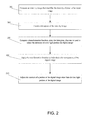
- FIG. 2 illustrates a method of processing digital images in accordance with an embodiment of the invention.
- FIG. 3 illustrates an exemplary histogram that includes intensity data of an intensity image in accordance with an embodiment of the invention.
- FIG. 4 illustrates an exemplary method that may be used to compute a transformation function in accordance with an embodiment of the invention.
- FIG. 5 illustrates an exemplary transformation function in accordance with an embodiment of the invention.
- FIG. 6A illustrates an image prior to undergoing the image processing herein.
- FIG. 6B illustrates an image that has undergone processing in accordance with an embodiment of the invention.
- FIG. 1 illustrates an exemplary mobile terminal 10 that may be used to implement aspects of the invention.
- a mobile terminal 10 may include a processor 128 connected to a user interface 130 , a memory 134 and/or other storage, a display 136 and a camera 156 .
- Mobile terminal 10 may also include a battery 150 , a speaker 152 and antennas 154 .
- User interface 130 may further include a keypad, touch screen, voice interface, one or more arrow keys, joy-stick, data glove, mouse, roller ball, touch screen, or the like.
- Computer executable instructions and data used by processor 128 and other components within mobile terminal 10 may be stored in computer readable memory 134 .
- Memory 134 may be implemented with any combination of read only memory modules or random access memory modules, optionally including both volatile and nonvolatile memory and optionally being detachable.
- Software 140 may be stored within memory 134 and/or storage to provide instructions to processor 128 for enabling mobile terminal 10 to perform various functions.
- some or all of mobile terminal 10 computer executable instructions may be embodied in hardware or firmware (not shown).
- Mobile terminal 10 may be configured to send and receive transmissions based on the Bluetooth standard, through a specific Bluetooth module 141 . Additionally, mobile terminal 10 may also be configured to receive, decode and process transmissions through an FM/AM radio receiver 142 , a wireless local area network (WLAN) transceiver 143 , and a telecommunications transceiver 144 . In one aspect of the invention, mobile terminal 10 may receive radio data stream (RDS) messages. Mobile terminal 10 may be equipped with other receivers/transceivers, e.g., one or more of a Digital Audio Broadcasting (DAB) receiver, a Digital Radio Musice (DRM) receiver, a Forward Link Only (FLO) receiver, a Digital Multimedia Broadcasting (DMB) receiver, etc.
- DAB Digital Audio Broadcasting
- DRM Digital Radio Mondiale
- FLO Forward Link Only
- DMB Digital Multimedia Broadcasting
- Hardware may be combined to provide a single receiver that receives and interprets multiple formats and transmission standards, as desired. That is, each receiver in a mobile terminal device may share parts or subassemblies with one or more other receivers in the mobile terminal device, or each receiver may be an independent subassembly.
- FIG. 2 illustrates a method of processing digital images in accordance with an embodiment of the invention.
- step 202 intensity image that identifies the intensity of pixels of an input image is computed.
- the input image may be in a compressed or uncompressed RGB format such as JPEG and TIFF.
- the input image may be in the form of unprocessed data received from an image sensor of a digital camera.
- the intensity image may be computed using the following formula:
- y ⁇ ( i , j ) r ⁇ ( i , j ) + b ⁇ ( i , j ) + g ⁇ ( i , j ) 3 ( 1 )
- i identifies a pixel row
- j identifies a pixel column.
- the intensity of individual red, green and blue pixels are identified by r(i,j), g(i,j) and b(i,j) respectively.
- a histogram of the intensity image is created.
- the type of histogram created in step 204 may be a conventional histogram used in connection with the processing of typical digital images.
- FIG. 3 illustrates an exemplary histogram 300 that includes intensity data of an intensity image. As is known in the art, the quantities of low light pixels are shown toward the left of the histogram and the quantities of bright pixels are shown toward the right. Histogram 300 corresponds to an image having a large number of low light or dark pixels and relatively few bright pixels.
- step 206 a transformation function is computed to adjust the intensity of a low light portion of the digital image.
- the computation performed in step 206 may use the histogram created in step 204 .
- FIG. 4 illustrates an exemplary method that may be used to compute the transformation function.
- step 402 the maximum intensity value MAX in the low light portion of the histogram and its position M are estimated. In one embodiment:
- the position M in the histogram corresponds to the value MAX.
- the low light portion of the histogram is analyzed so that the intensity and contrast of dark regions of the image can be adjusted.
- step 404 the width of the low light portion of the histogram is estimated.
- Step 404 may be used to determine the portion of the low light region containing the most pixels.
- a threshold value such as 0.3, is selected and the range of the histogram [Imin,Imax] is computed as:
- Input images that have a large number of dark pixels that have almost the same intensity level will result in a small range (Imin and Imax will be close to each other).
- the amount of processing that ultimately takes place is inversely related to the range.
- Input images having large ranges already have a large dynamic range and require less processing.
- the maximum and the minimum strength of the processing are limited in order to limit over-processing or smoothing the input image.
- step 406 parameters of the transformation function are estimated and the transformation function is fit to the histogram.
- the transformation function may be fitted to the range [Imin,Imax] determined above.
- the transformation function f(i,j) is defined as
- FIG. 5 illustrates an exemplary transformation function 500 .
- the maximum slope exists for inputs in the range [ ⁇ 1,1] and this is the reason why the pixel values must be scaled. Subtracting the maximum intensity position M shifts the center of the correction function to the position of the maximum of the histogram.
- K in equation can result in saturation at the zero level or the 255 level if not chosen properly.
- a very large value of K for a transformation function enhance the contrast of the pixels that have values close to M but the other pixels will be simply put to 0 or 255. That is all pixels not located close to M will be black or white.
- K may have a non-fixed value when there is a desire for high contrast while avoiding over saturation.
- a wide range [Imin,Imax] may result in a small K that prevents saturation of the other pixels and also decrease the strength of the processing.
- a narrow range [Imin,Imax] may result in a larger K in order to better increase the contrast and intensity. However in any case the pixels that are at the extreme value of the intensity (around 0 and around 255 intensity levels) should not be saturated.
- the scaling factor 255 ensures that the pixels after applying the correction function are on the range [0,255].
- the value of the parameter K estimated by equation (9), can be too large or to small. In such situations its value should be bounded.
- An exemplary minimum value Kmin equals 3 and an exemplary maximum value K max ⁇ [8,10].
- the fixed value Kmin may be chosen such that the transformation function f(i,j) is linear inside the input range [ ⁇ 1,1].
- the maximum value of K can be selected fixed or it can be a user defined parameter. Modifications to Kmax can increase or decrease the maximum strength of the processing.
- step 208 the transformation function is applied to individual color components of the digital image.
- the minimum and maximum values of r(i,j) are determined so that they may be preserved as follows:
- r ⁇ ⁇ ( i , j ) max_r 1 + exp ⁇ ( - K ⁇ ( r ⁇ ( i , j ) - M ) 255 ) ( 11 )
- the minimum and the maximum pixel values of the red color component may be restored as follows:
- a ⁇ ( i , j ) ⁇ ⁇ 0 ⁇ if ⁇ ⁇ r ⁇ ( i , j ) ⁇ M ⁇ f ⁇ ( y ⁇ ( i , j ) ) - 0.5 255 ⁇ otherwise ( 14 )
- red may then be repeated for other color components, such as green and blue.
- step 210 the contrast of a portion of the digital image other than the low light portion of the digital image is adjusted.
- step 210 includes modifying the level of the local contrast, but not the intensity.
- the transformation function f(i,j) may be used to indicate which pixels were processed in the previous steps.
- the contrast of a portion of the digital image other than the low light portion of the digital image may be adjusted by first computing a gain map g(i,j) according to:
- a maximum value of the gain map is 2 and it is obtained for the pixels that were not processed at previous steps.
- a maximum value larger than 2 can be used in order to have a stronger contrast processing.
- the maximum value of the gain can also be selected as a user defined parameter which can be used to fine tune the processing quality.
- d 2 ⁇ circumflex over (r) ⁇ ( i,j ) ⁇ ⁇ circumflex over (r) ⁇ ( i,j +1)
- s 1 ⁇ circumflex over (r) ⁇ ( i,j )+ ⁇ circumflex over (r) ⁇ ( i,j+ 1)
- the image may then be reconstructed according to:
- Rout ⁇ ( i , j ) d ⁇ ⁇ ⁇ 1 ⁇ ( i , j ) + d ⁇ ⁇ ⁇ 2 ⁇ ( i , j ) + s ⁇ ⁇ 1 ⁇ ( i , j ) + s ⁇ ⁇ 2 ⁇ ( i , j ) 4 ( 17 )
- image clipping may be performed according to:
- Rout ⁇ ( i , j ) ⁇ ⁇ 0 ⁇ if ⁇ ⁇ Rout ⁇ ( i , j ) ⁇ 0 ⁇ 255 ⁇ if ⁇ ⁇ Rout ⁇ ( i , j ) > 255 ⁇ Rout ⁇ ( i , j ) ⁇ otherwise ( 18 )
- the remaining color components may be processed using similar procedures.
- FIG. 6A illustrates an image 600 prior to undergoing the image processing described above.
- FIG. 6B illustrates an image 602 that has undergone processing in accordance with an embodiment of the invention. One can see that the intensity of the low light portion of image 602 exceeds the intensity of the low light portion of image 600 .
Abstract
Description
where i identifies a pixel row, j identifies a pixel column. The intensity of individual red, green and blue pixels are identified by r(i,j), g(i,j) and b(i,j) respectively.
h(m)=nr of pixels in the range [m−0.5;m+0.5] with m=0, . . . , 255 (2)
Imin=M−max{|M−R1|,|M−R2|}and Imax=M+max{|M−R1|,|M−R2|} (6)
ƒ(Imax)=0.7*255 (8)
{circumflex over (r)}(i,j)=(1=a(i,j)){circumflex over (r)}(i,j)+a(i,j)r(i,j) (13)
d1={circumflex over (r)}(i,j)−{circumflex over (r)}(i+1,j)
s1={circumflex over (r)}(i,j)+{circumflex over (r)}(i+1,j)
d2={circumflex over (r)}(i,j)−{circumflex over (r)}(i,j+1)
s1={circumflex over (r)}(i,j)+{circumflex over (r)}(i,j+1) (15)
{circumflex over (d)}1(i,j)=g(i,j)d1(i,j)
{circumflex over (d)}2(i,j)=g(i,j)d2)(i,j) (16)
Claims (21)
h(m)=nr of pixels in the range [m−0.5;m+0.5] with m=0, . . . , 255.
h(m)=nr of pixels in the range [m−0.5;m+0.5] with m=0, . . . , 255.
Priority Applications (1)
| Application Number | Priority Date | Filing Date | Title |
|---|---|---|---|
| US11/464,645 US7796830B2 (en) | 2006-08-15 | 2006-08-15 | Adaptive contrast optimization of digital color images |
Applications Claiming Priority (1)
| Application Number | Priority Date | Filing Date | Title |
|---|---|---|---|
| US11/464,645 US7796830B2 (en) | 2006-08-15 | 2006-08-15 | Adaptive contrast optimization of digital color images |
Publications (2)
| Publication Number | Publication Date |
|---|---|
| US20080044083A1 US20080044083A1 (en) | 2008-02-21 |
| US7796830B2 true US7796830B2 (en) | 2010-09-14 |
Family
ID=39101487
Family Applications (1)
| Application Number | Title | Priority Date | Filing Date |
|---|---|---|---|
| US11/464,645 Expired - Fee Related US7796830B2 (en) | 2006-08-15 | 2006-08-15 | Adaptive contrast optimization of digital color images |
Country Status (1)
| Country | Link |
|---|---|
| US (1) | US7796830B2 (en) |
Cited By (1)
| Publication number | Priority date | Publication date | Assignee | Title |
|---|---|---|---|---|
| US11094045B2 (en) * | 2016-06-21 | 2021-08-17 | Zhejiang Dahua Technology Co., Ltd. | Systems and methods for image processing |
Families Citing this family (8)
| Publication number | Priority date | Publication date | Assignee | Title |
|---|---|---|---|---|
| US7796830B2 (en) * | 2006-08-15 | 2010-09-14 | Nokia Corporation | Adaptive contrast optimization of digital color images |
| US8111943B2 (en) * | 2009-04-15 | 2012-02-07 | The United States Of America As Represented By The Administrator Of The National Aeronautics And Space Administration | Smart image enhancement process |
| JP2010278724A (en) * | 2009-05-28 | 2010-12-09 | Olympus Corp | Image processing apparatus, image processing method, and image processing program |
| WO2011072788A2 (en) * | 2009-12-18 | 2011-06-23 | Daimler Ag | Display method and display device for a vehicle |
| DE102009058887A1 (en) * | 2009-12-18 | 2011-06-22 | Daimler AG, 70327 | Method for displaying information content e.g. video information of motor vehicle on LCD, involves adjusting brightness values of content based on environmental condition, and representing adjusted brightness values on display surface |
| CN109146815B (en) * | 2018-08-20 | 2022-08-30 | 深圳创维-Rgb电子有限公司 | Image contrast adjusting method and device and computer equipment |
| WO2021086171A1 (en) * | 2019-10-29 | 2021-05-06 | Mimos Berhad | A system and method for monitoring human behaviour |
| CN113592739A (en) * | 2021-07-30 | 2021-11-02 | 浙江大华技术股份有限公司 | Method and device for correcting lens shadow and storage medium |
Citations (13)
| Publication number | Priority date | Publication date | Assignee | Title |
|---|---|---|---|---|
| US4074289A (en) * | 1974-07-17 | 1978-02-14 | Asahi Kogaku Kogyo Kabushiki Kaisha | Camera exposure control system adapted to adjust both the diaphragm and the shutter |
| US4174526A (en) * | 1977-02-21 | 1979-11-13 | U.S. Philips Corporation | Television camera comprising a diaphragm control and a controllable picture signal amplification circuit |
| US4264163A (en) * | 1979-01-29 | 1981-04-28 | Eastman Kodak Company | Exposure control apparatus with compensation for film reciprocity failure |
| US4550993A (en) * | 1983-02-01 | 1985-11-05 | Minolta Camera Kabushiki Kaisha | Device for providing a camera system with an information for a focus adjustment |
| US5049730A (en) * | 1990-04-23 | 1991-09-17 | The United States Of America As Represented By The Secretary Of The Army | Automatic shutter for low light sensing and amplifying device |
| US5157501A (en) * | 1988-11-17 | 1992-10-20 | Samsung Electronics Co., Ltd. | Blooming measuring method for solid state image pick-up device, and apparatus suitable for the measuring |
| US5467404A (en) | 1991-08-14 | 1995-11-14 | Agfa-Gevaert | Method and apparatus for contrast enhancement |
| US5954653A (en) * | 1997-05-07 | 1999-09-21 | General Electric Company | Method and apparatus for automatically enhancing contrast in projected ultrasound image |
| US20030160882A1 (en) * | 2000-02-19 | 2003-08-28 | Christiane Henno | Video sensor chip circuit |
| US20080044083A1 (en) * | 2006-08-15 | 2008-02-21 | Nokia Corporation | Adaptive contrast optimization of digital color images |
| US7474847B2 (en) * | 2003-06-30 | 2009-01-06 | Nokia Corporation | Method and system in digital imaging for adjusting exposure and a corresponding device |
| US7522781B2 (en) * | 2005-02-11 | 2009-04-21 | Samsung Electronics Co., Ltd. | Method and apparatus for image processing based on a mapping function |
| US7583297B2 (en) * | 2004-01-23 | 2009-09-01 | Sony Corporation | Image processing method, image processing apparatus, and computer program used therewith |
-
2006
- 2006-08-15 US US11/464,645 patent/US7796830B2/en not_active Expired - Fee Related
Patent Citations (13)
| Publication number | Priority date | Publication date | Assignee | Title |
|---|---|---|---|---|
| US4074289A (en) * | 1974-07-17 | 1978-02-14 | Asahi Kogaku Kogyo Kabushiki Kaisha | Camera exposure control system adapted to adjust both the diaphragm and the shutter |
| US4174526A (en) * | 1977-02-21 | 1979-11-13 | U.S. Philips Corporation | Television camera comprising a diaphragm control and a controllable picture signal amplification circuit |
| US4264163A (en) * | 1979-01-29 | 1981-04-28 | Eastman Kodak Company | Exposure control apparatus with compensation for film reciprocity failure |
| US4550993A (en) * | 1983-02-01 | 1985-11-05 | Minolta Camera Kabushiki Kaisha | Device for providing a camera system with an information for a focus adjustment |
| US5157501A (en) * | 1988-11-17 | 1992-10-20 | Samsung Electronics Co., Ltd. | Blooming measuring method for solid state image pick-up device, and apparatus suitable for the measuring |
| US5049730A (en) * | 1990-04-23 | 1991-09-17 | The United States Of America As Represented By The Secretary Of The Army | Automatic shutter for low light sensing and amplifying device |
| US5467404A (en) | 1991-08-14 | 1995-11-14 | Agfa-Gevaert | Method and apparatus for contrast enhancement |
| US5954653A (en) * | 1997-05-07 | 1999-09-21 | General Electric Company | Method and apparatus for automatically enhancing contrast in projected ultrasound image |
| US20030160882A1 (en) * | 2000-02-19 | 2003-08-28 | Christiane Henno | Video sensor chip circuit |
| US7474847B2 (en) * | 2003-06-30 | 2009-01-06 | Nokia Corporation | Method and system in digital imaging for adjusting exposure and a corresponding device |
| US7583297B2 (en) * | 2004-01-23 | 2009-09-01 | Sony Corporation | Image processing method, image processing apparatus, and computer program used therewith |
| US7522781B2 (en) * | 2005-02-11 | 2009-04-21 | Samsung Electronics Co., Ltd. | Method and apparatus for image processing based on a mapping function |
| US20080044083A1 (en) * | 2006-08-15 | 2008-02-21 | Nokia Corporation | Adaptive contrast optimization of digital color images |
Non-Patent Citations (18)
| Title |
|---|
| Dah-Chung Chang, Wen-Rong Wu-"Image Contrast Enhancement Based on a Histogram Transformation of Local Standard Deviation", in IEEE Transactions on Medical Imaging, vol. 17, No. 4, Aug. 1998, pp. 518-531. |
| Dah-Chung Chang, Wen-Rong Wu—"Image Contrast Enhancement Based on a Histogram Transformation of Local Standard Deviation", in IEEE Transactions on Medical Imaging, vol. 17, No. 4, Aug. 1998, pp. 518-531. |
| Hayit Greenspan, Charles H. Anderson and Sofia Akber,-"Image Enhancement by Nonlinear Extrapolation in Frequency Space", in IEEE Transactions on Image Processing, vol. 9, No. 6, Jun. 2000, pp. 1035-1048. |
| Hayit Greenspan, Charles H. Anderson and Sofia Akber,—"Image Enhancement by Nonlinear Extrapolation in Frequency Space", in IEEE Transactions on Image Processing, vol. 9, No. 6, Jun. 2000, pp. 1035-1048. |
| Jian Lu and Denis M. Healy, Jr,-"Contrast Enhancement Via Multiscale Gradient Transformation", in Proceedings of IEEE International Conference on Image Processing ICIP1994, pp. 482-486. |
| Jian Lu and Denis M. Healy, Jr,—"Contrast Enhancement Via Multiscale Gradient Transformation", in Proceedings of IEEE International Conference on Image Processing ICIP1994, pp. 482-486. |
| Jinshan Tang, Eli Peli and Scott Acton,-"Image Enhancement Using a Contrast Measure in the Compressed Domain", in IEEE Signal Processing Letters, vol. 10, No. 10, Oct. 2003, pp. 289-292. |
| Jinshan Tang, Eli Peli and Scott Acton,—"Image Enhancement Using a Contrast Measure in the Compressed Domain", in IEEE Signal Processing Letters, vol. 10, No. 10, Oct. 2003, pp. 289-292. |
| Joung-Youn Kim, Lee-Sup Kim and Seung-Ho Hwang,-"An Advanced Contrast Enhancement using Partially Overlapped Sub-Block Histogram Equalization", in IEEE transactions on Circuits and Systems for Video Technology, vol. 11, No. 4, Apr. 2001, pp. 475-484. |
| Joung-Youn Kim, Lee-Sup Kim and Seung-Ho Hwang,—"An Advanced Contrast Enhancement using Partially Overlapped Sub-Block Histogram Equalization", in IEEE transactions on Circuits and Systems for Video Technology, vol. 11, No. 4, Apr. 2001, pp. 475-484. |
| KokKeong Tan and John P. Oakley,-"Enhancement of Color Images in Poor Visibility Conditions", In Proceedings of IEEE International Conference on Image Processing ICIP2000, pp. 788-791. |
| KokKeong Tan and John P. Oakley,—"Enhancement of Color Images in Poor Visibility Conditions", In Proceedings of IEEE International Conference on Image Processing ICIP2000, pp. 788-791. |
| M. A. Wirth and D. Nikitenko,-"Applications of Fuzzy Morphology to Contrast Enhancement", in IEEE Annual Meeting of the North American Fuzzy Information Processing Society, NAFIPS2005, pp. 355-360. |
| M. A. Wirth and D. Nikitenko,—"Applications of Fuzzy Morphology to Contrast Enhancement", in IEEE Annual Meeting of the North American Fuzzy Information Processing Society, NAFIPS2005, pp. 355-360. |
| Sarif Kumar and C. A. Murthy,-"Hue-Preserving Color Image Enhancement without Gamut Problem", in IEEE Transactions on Image Processing, vol. 12, No. 12, Dec. 2003, pp. 1591-1598. |
| Sarif Kumar and C. A. Murthy,—"Hue-Preserving Color Image Enhancement without Gamut Problem", in IEEE Transactions on Image Processing, vol. 12, No. 12, Dec. 2003, pp. 1591-1598. |
| Yeong-Taeg Kim,-"Contrast Enhancement Using Brightness Preserving Bi-Histogram Equalization", in IEEE Transactions on Consumer Electronics, vol. 43, No. 1, Feb. 1997, pp. 1-8. |
| Yeong-Taeg Kim,—"Contrast Enhancement Using Brightness Preserving Bi-Histogram Equalization", in IEEE Transactions on Consumer Electronics, vol. 43, No. 1, Feb. 1997, pp. 1-8. |
Cited By (1)
| Publication number | Priority date | Publication date | Assignee | Title |
|---|---|---|---|---|
| US11094045B2 (en) * | 2016-06-21 | 2021-08-17 | Zhejiang Dahua Technology Co., Ltd. | Systems and methods for image processing |
Also Published As
| Publication number | Publication date |
|---|---|
| US20080044083A1 (en) | 2008-02-21 |
Similar Documents
| Publication | Publication Date | Title |
|---|---|---|
| US7796830B2 (en) | Adaptive contrast optimization of digital color images | |
| US7835588B2 (en) | Contrast optimization of images | |
| US9898807B2 (en) | Image processing device, imaging device, image processing method, and program | |
| US20070165962A1 (en) | Method and apparatus for bilateral high pass filter | |
| US7773158B2 (en) | Visual processing device, display device, and integrated circuit | |
| KR100756318B1 (en) | Image Processing Method and System Using Gain-Controllable Clipped Histogram Equalization | |
| US8639050B2 (en) | Dynamic adjustment of noise filter strengths for use with dynamic range enhancement of images | |
| US9710895B2 (en) | Image processing device, image capture device, image processing method, and program | |
| US20100278423A1 (en) | Methods and systems for contrast enhancement | |
| US20080031541A1 (en) | Better Picture For Inexpensive Cameras | |
| US9153015B2 (en) | Image processing device and method | |
| CN107635103B (en) | Image processing method, mobile terminal and medium product | |
| US7606438B2 (en) | Image signal processor and image signal processing method | |
| CN105960658B (en) | Image processing apparatus, image capturing apparatus, image processing method, and non-transitory storage medium that can be processed by computer | |
| US8526736B2 (en) | Image processing apparatus for correcting luminance and method thereof | |
| JP2011014958A (en) | Image signal processing device | |
| US8208045B2 (en) | Method and system for reducing noise in image data | |
| US10051252B1 (en) | Method of decaying chrominance in images | |
| US8754990B2 (en) | Method and system for processing chroma signals | |
| US7595911B2 (en) | Methods and systems for descreening a digital image | |
| JP2008305122A (en) | Image-processing apparatus, image processing method and program | |
| US7570808B2 (en) | Better picture for inexpensive cameras | |
| US7362361B2 (en) | Noise suppressing circuit using luminance detection | |
| JP2004259177A (en) | Image processing device and program | |
| JP2001229375A (en) | Image processor, image processing method and recording medium |
Legal Events
| Date | Code | Title | Description |
|---|---|---|---|
| AS | Assignment |
Owner name: NOKIA CORPORATION, FINLAND Free format text: ASSIGNMENT OF ASSIGNORS INTEREST;ASSIGNORS:BILCU, RADU;VEHVILAINEN, MARKKU;REEL/FRAME:018236/0542;SIGNING DATES FROM 20060822 TO 20060824 Owner name: NOKIA CORPORATION, FINLAND Free format text: ASSIGNMENT OF ASSIGNORS INTEREST;ASSIGNORS:BILCU, RADU;VEHVILAINEN, MARKKU;SIGNING DATES FROM 20060822 TO 20060824;REEL/FRAME:018236/0542 |
|
| FEPP | Fee payment procedure |
Free format text: PAYOR NUMBER ASSIGNED (ORIGINAL EVENT CODE: ASPN); ENTITY STATUS OF PATENT OWNER: LARGE ENTITY |
|
| STCF | Information on status: patent grant |
Free format text: PATENTED CASE |
|
| FPAY | Fee payment |
Year of fee payment: 4 |
|
| AS | Assignment |
Owner name: NOKIA TECHNOLOGIES OY, FINLAND Free format text: ASSIGNMENT OF ASSIGNORS INTEREST;ASSIGNOR:NOKIA CORPORATION;REEL/FRAME:035581/0654 Effective date: 20150116 |
|
| AS | Assignment |
Owner name: PROVENANCE ASSET GROUP LLC, CONNECTICUT Free format text: ASSIGNMENT OF ASSIGNORS INTEREST;ASSIGNORS:NOKIA TECHNOLOGIES OY;NOKIA SOLUTIONS AND NETWORKS BV;ALCATEL LUCENT SAS;REEL/FRAME:043877/0001 Effective date: 20170912 Owner name: NOKIA USA INC., CALIFORNIA Free format text: SECURITY INTEREST;ASSIGNORS:PROVENANCE ASSET GROUP HOLDINGS, LLC;PROVENANCE ASSET GROUP LLC;REEL/FRAME:043879/0001 Effective date: 20170913 Owner name: CORTLAND CAPITAL MARKET SERVICES, LLC, ILLINOIS Free format text: SECURITY INTEREST;ASSIGNORS:PROVENANCE ASSET GROUP HOLDINGS, LLC;PROVENANCE ASSET GROUP, LLC;REEL/FRAME:043967/0001 Effective date: 20170913 |
|
| FEPP | Fee payment procedure |
Free format text: 7.5 YR SURCHARGE - LATE PMT W/IN 6 MO, LARGE ENTITY (ORIGINAL EVENT CODE: M1555) |
|
| MAFP | Maintenance fee payment |
Free format text: PAYMENT OF MAINTENANCE FEE, 8TH YEAR, LARGE ENTITY (ORIGINAL EVENT CODE: M1552) Year of fee payment: 8 |
|
| AS | Assignment |
Owner name: NOKIA US HOLDINGS INC., NEW JERSEY Free format text: ASSIGNMENT AND ASSUMPTION AGREEMENT;ASSIGNOR:NOKIA USA INC.;REEL/FRAME:048370/0682 Effective date: 20181220 |
|
| AS | Assignment |
Owner name: PROVENANCE ASSET GROUP LLC, CONNECTICUT Free format text: RELEASE BY SECURED PARTY;ASSIGNOR:CORTLAND CAPITAL MARKETS SERVICES LLC;REEL/FRAME:058983/0104 Effective date: 20211101 Owner name: PROVENANCE ASSET GROUP HOLDINGS LLC, CONNECTICUT Free format text: RELEASE BY SECURED PARTY;ASSIGNOR:CORTLAND CAPITAL MARKETS SERVICES LLC;REEL/FRAME:058983/0104 Effective date: 20211101 Owner name: PROVENANCE ASSET GROUP LLC, CONNECTICUT Free format text: RELEASE BY SECURED PARTY;ASSIGNOR:NOKIA US HOLDINGS INC.;REEL/FRAME:058363/0723 Effective date: 20211129 Owner name: PROVENANCE ASSET GROUP HOLDINGS LLC, CONNECTICUT Free format text: RELEASE BY SECURED PARTY;ASSIGNOR:NOKIA US HOLDINGS INC.;REEL/FRAME:058363/0723 Effective date: 20211129 |
|
| AS | Assignment |
Owner name: RPX CORPORATION, CALIFORNIA Free format text: ASSIGNMENT OF ASSIGNORS INTEREST;ASSIGNOR:PROVENANCE ASSET GROUP LLC;REEL/FRAME:059352/0001 Effective date: 20211129 |
|
| FEPP | Fee payment procedure |
Free format text: MAINTENANCE FEE REMINDER MAILED (ORIGINAL EVENT CODE: REM.); ENTITY STATUS OF PATENT OWNER: LARGE ENTITY |
|
| LAPS | Lapse for failure to pay maintenance fees |
Free format text: PATENT EXPIRED FOR FAILURE TO PAY MAINTENANCE FEES (ORIGINAL EVENT CODE: EXP.); ENTITY STATUS OF PATENT OWNER: LARGE ENTITY |
|
| STCH | Information on status: patent discontinuation |
Free format text: PATENT EXPIRED DUE TO NONPAYMENT OF MAINTENANCE FEES UNDER 37 CFR 1.362 |
|
| FP | Lapsed due to failure to pay maintenance fee |
Effective date: 20220914 |