US7798638B2 - Eyeglasses with integrated video display - Google Patents
Eyeglasses with integrated video display Download PDFInfo
- Publication number
- US7798638B2 US7798638B2 US12/484,952 US48495209A US7798638B2 US 7798638 B2 US7798638 B2 US 7798638B2 US 48495209 A US48495209 A US 48495209A US 7798638 B2 US7798638 B2 US 7798638B2
- Authority
- US
- United States
- Prior art keywords
- video
- frame
- video display
- pivot member
- axis
- Prior art date
- Legal status (The legal status is an assumption and is not a legal conclusion. Google has not performed a legal analysis and makes no representation as to the accuracy of the status listed.)
- Active
Links
- 238000007373 indentation Methods 0.000 claims description 6
- 230000014759 maintenance of location Effects 0.000 abstract description 2
- 239000011521 glass Substances 0.000 description 5
- 239000004973 liquid crystal related substance Substances 0.000 description 3
- 238000004891 communication Methods 0.000 description 2
- 230000002708 enhancing effect Effects 0.000 description 2
- 239000000463 material Substances 0.000 description 2
- 238000012986 modification Methods 0.000 description 2
- 230000004048 modification Effects 0.000 description 2
- 230000004297 night vision Effects 0.000 description 2
- 230000003287 optical effect Effects 0.000 description 2
- 230000000717 retained effect Effects 0.000 description 2
- 230000003466 anti-cipated effect Effects 0.000 description 1
- 238000005516 engineering process Methods 0.000 description 1
- 239000002071 nanotube Substances 0.000 description 1
- 239000005304 optical glass Substances 0.000 description 1
- 230000008707 rearrangement Effects 0.000 description 1
- 239000004065 semiconductor Substances 0.000 description 1
- 230000037072 sun protection Effects 0.000 description 1
Images


Classifications
-
- G—PHYSICS
- G02—OPTICS
- G02B—OPTICAL ELEMENTS, SYSTEMS OR APPARATUS
- G02B27/00—Optical systems or apparatus not provided for by any of the groups G02B1/00 - G02B26/00, G02B30/00
- G02B27/01—Head-up displays
- G02B27/017—Head mounted
- G02B27/0172—Head mounted characterised by optical features
-
- G—PHYSICS
- G02—OPTICS
- G02B—OPTICAL ELEMENTS, SYSTEMS OR APPARATUS
- G02B27/00—Optical systems or apparatus not provided for by any of the groups G02B1/00 - G02B26/00, G02B30/00
- G02B27/01—Head-up displays
- G02B27/017—Head mounted
- G02B27/0176—Head mounted characterised by mechanical features
-
- G—PHYSICS
- G02—OPTICS
- G02C—SPECTACLES; SUNGLASSES OR GOGGLES INSOFAR AS THEY HAVE THE SAME FEATURES AS SPECTACLES; CONTACT LENSES
- G02C11/00—Non-optical adjuncts; Attachment thereof
- G02C11/10—Electronic devices other than hearing aids
-
- G—PHYSICS
- G02—OPTICS
- G02C—SPECTACLES; SUNGLASSES OR GOGGLES INSOFAR AS THEY HAVE THE SAME FEATURES AS SPECTACLES; CONTACT LENSES
- G02C5/00—Constructions of non-optical parts
- G02C5/001—Constructions of non-optical parts specially adapted for particular purposes, not otherwise provided for or not fully classifiable according to technical characteristics, e.g. therapeutic glasses
-
- G—PHYSICS
- G02—OPTICS
- G02C—SPECTACLES; SUNGLASSES OR GOGGLES INSOFAR AS THEY HAVE THE SAME FEATURES AS SPECTACLES; CONTACT LENSES
- G02C5/00—Constructions of non-optical parts
- G02C5/14—Side-members
- G02C5/146—Side-members having special front end
-
- G—PHYSICS
- G02—OPTICS
- G02B—OPTICAL ELEMENTS, SYSTEMS OR APPARATUS
- G02B27/00—Optical systems or apparatus not provided for by any of the groups G02B1/00 - G02B26/00, G02B30/00
- G02B27/01—Head-up displays
- G02B27/0101—Head-up displays characterised by optical features
- G02B2027/0123—Head-up displays characterised by optical features comprising devices increasing the field of view
-
- G—PHYSICS
- G02—OPTICS
- G02B—OPTICAL ELEMENTS, SYSTEMS OR APPARATUS
- G02B27/00—Optical systems or apparatus not provided for by any of the groups G02B1/00 - G02B26/00, G02B30/00
- G02B27/01—Head-up displays
- G02B27/0101—Head-up displays characterised by optical features
- G02B2027/0127—Head-up displays characterised by optical features comprising devices increasing the depth of field
-
- G—PHYSICS
- G02—OPTICS
- G02B—OPTICAL ELEMENTS, SYSTEMS OR APPARATUS
- G02B27/00—Optical systems or apparatus not provided for by any of the groups G02B1/00 - G02B26/00, G02B30/00
- G02B27/01—Head-up displays
- G02B27/0101—Head-up displays characterised by optical features
- G02B2027/0138—Head-up displays characterised by optical features comprising image capture systems, e.g. camera
-
- G—PHYSICS
- G02—OPTICS
- G02B—OPTICAL ELEMENTS, SYSTEMS OR APPARATUS
- G02B27/00—Optical systems or apparatus not provided for by any of the groups G02B1/00 - G02B26/00, G02B30/00
- G02B27/01—Head-up displays
- G02B27/0149—Head-up displays characterised by mechanical features
- G02B2027/0154—Head-up displays characterised by mechanical features with movable elements
- G02B2027/0156—Head-up displays characterised by mechanical features with movable elements with optionally usable elements
-
- G—PHYSICS
- G02—OPTICS
- G02B—OPTICAL ELEMENTS, SYSTEMS OR APPARATUS
- G02B27/00—Optical systems or apparatus not provided for by any of the groups G02B1/00 - G02B26/00, G02B30/00
- G02B27/01—Head-up displays
- G02B27/017—Head mounted
- G02B2027/0178—Eyeglass type
-
- G—PHYSICS
- G02—OPTICS
- G02B—OPTICAL ELEMENTS, SYSTEMS OR APPARATUS
- G02B7/00—Mountings, adjusting means, or light-tight connections, for optical elements
- G02B7/02—Mountings, adjusting means, or light-tight connections, for optical elements for lenses
- G02B7/12—Adjusting pupillary distance of binocular pairs
Definitions
- the present invention relates generally to eyeglasses and, more particularly, to eyeglasses adapted for viewing video signals while having the appearance and function of ordinary eyewear.
- Eyeglasses having liquid crystal display (LCD) screens and earphones are currently available, but such eyewear does not retain the appearance of conventional or stylish optical glasses or sunglasses.
- Detachable viewers for mounting to conventional eyewear for either right or left eye viewing and liquid-crystal glasses having clear optics adapted to fit over prescription eyewear are examples.
- U.S. Pat. No. 6,065,832 for “Eyeglasses With Integrated Rear View Mirrors” which issued to Robert J. Fuziak on May 23, 2000, describes a pair of eyeglasses including rear view mirrors, each having a mirror surface that may be folded forwardly and outwardly to an open position for use, and that may also be folded rearwardly and inwardly to a closed position for retention by the temple members of the eyeglasses when not in use, such that when in the closed position against the temple members, the eyeglasses present the appearance of conventional eyeglasses.
- Another object of the invention is to provide eyeglasses suitable for viewing video signals and for obtaining still or video camera pictures, while maintaining the appearance and function of ordinary eyewear when the displays are not in use.
- the video display integrally combined with a pair of eyeglasses includes in combination: a frame having left and right temple extension portions extending rearward at left and right sides thereof; left and right lenses mounted within the frame; left and right ear pieces at least one each ear piece having a receiving portion on an outer surface thereof; a right, single-axis pivot member for pivotably attaching the right ear piece to the right temple extension portion of the frame, and a left, single-axis pivot member for pivotably attaching the left ear piece to the left temple extension portion of the frame; at least one single-axis pivot member having the pivot axis thereof collinear with either the axis of the right pivot member or the axis of the left pivot member; at least one video display holder having a top edge and a bottom edge, and a first surface facing the frame; at least one video display disposed on the first surface; a two-axis
- the video display integrally combined with a pair of eyeglasses includes in combination: a frame having a left side and a right side; left and right lenses mounted within the frame; left and right ear pieces, at least one ear piece having a receiving portion on an outer surface thereof; a right, single-axis pivot member for pivotably attaching the right ear piece to the right side of the frame, and a left, single-axis pivot member for pivotably attaching the left ear piece to the left side of the frame; at least one single-axis pivot member having the pivot axis thereof collinear with either the axis of the right pivot member or the axis of the left pivot member; at least one video display holder having a top edge and a bottom edge, and a first surface facing the frame; at least one video display disposed on the first surface; a second single-axis pivot member attached to the at least one display holder between the top edge and the bottom edge thereof; an arm having an
- the video display integrally combined with a pair of eyeglasses includes in combination: a frame having a left side and a right side; left and right lenses mounted within the frame; left and right temple ear pieces at least one ear piece having a receiving portion on an outer surface thereof; a right, single-axis pivot member for pivotably attaching the right ear piece to the right side of the frame, and a left, single-axis pivot member for pivotably attaching the left ear piece to the left side of the frame; a single-axis pivot member having the pivot axis thereof collinear with either the axis of the right pivot member or the axis of the left pivot member; at least one video display holder having a top edge and a bottom edge, and a first surface facing the frame; at least one video display disposed on the first surface; a three-axis pivot member attached to the at least one display holder between the top edge and the bottom edge thereof; an arm having an end
- Benefits and advantages of the present invention include, but are not limited to, an integrated eyeglass system adapted for viewing at least one video display through a corresponding lens thereof while appearing and functioning like ordinary eyewear when the at least one display is pivoted out of the way of the corresponding lens and stored in or on the corresponding ear piece.
- the location of the at least one video display away from a user's eyes provides additional safety over many current wearable display systems.
- FIG. 1A is a schematic representation of an embodiment of the eyeglasses of the present invention having rearward extending left and right temple extension portions at left and right sides thereof, wherein the at least one video display holder is shown in its deployed position with a camera, flash attachment and microphone facing away from the lenses;
- FIG. 1B is a schematic representation of the eyeglasses shown in FIG. 1A hereof with the cover portion shielding a two-axis pivot member removed to better reveal the attachment of the two-axis pivot member to an edge of the video display holder between the top and bottom edges thereof;
- FIG. 1C is a schematic representation of the eyeglasses shown in FIG. 1A hereof illustrating the video display holder in its stored position in a receiving portion in the left temple member, the cover portion covering the pivot member enhancing the smooth appearance of the left ear piece when the video display holder is stored therein.
- FIG. 2A is a schematic representation of an embodiment of the eyeglasses of the present invention having rearward extending left and right temple extension portions at left and right sides thereof, wherein the at least one video display holder is shown in its deployed position with a camera facing away from the lenses; while FIG. 2B is a schematic representation of the eyeglasses shown in FIG. 2A hereof illustrating the video display holder in its storage position in a receiving portion in the left ear piece, and a ball-type pivot member mounted to the surface of the video display holder facing the frame in the vicinity of an edge between the upper and lower edges thereof, thereby permitting the display holder to conceal the pivot member.
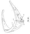
- FIG. 3A is a schematic representation of an embodiment of the eyeglasses of the present invention without rearward extending left and right temple extension portions, wherein the at least one video display holder is shown in its deployed position with a camera facing away from the lenses; while FIG. 3B is a schematic representation of the eyeglasses shown in FIG. 3A hereof illustrating the video display holder in its storage position in a receiving portion in the left ear piece, and another ball-type embodiment of the three-axis, ball-type pivot member mounted to an edge of the video display holder between the upper and lower edges thereof, thereby permitting the display holder conceal the pivot member.
- the present invention includes eyeglasses adapted for viewing video signals, while maintaining the appearance and function of ordinary eyewear.
- video signals may be viewed at adjustable distances from a viewer's eyes.
- the at least one arm may be a telescoping arm.
- Electronics such as video receivers and amplifiers, audio receivers and amplifiers, Bluetooth components, still and/or video cameras, including night-vision cameras and cameras having electrical and/or optical zoom capability, earphones, microphones, as examples; flash memory card readers, as an example, for driving and complementing the video displays; power supplies, such as batteries; and electrical connections among the various components, may be mounted on and/or in the eyeglasses, may be plugged into the eyeglasses or worn on the body of the user of the eyeglasses, or be used in various combinations thereof as is suitable for the intended applications in ways known to those having skill in the audio/video arts. It should be mentioned that at least some of the electrical components may cooperate using wireless technology.
- the present invention may give rise to safety concerns since viewing screens are commonly located on the inside of the eyewear; that is, between the lenses and the user's eyes.
- the present invention places the viewing screen(s) on the opposite side of the lenses from the user's eyes.
- the lenses of the present invention may be made from shatter proof materials. This may be of significance for military applications.
- FIG. 1A eyeglasses, 10 , are shown which may have a rearwardly curved frame member, 12 , for retaining conventional lenses, 14 a and 14 b , which may be prescription lenses, shatterproof lenses, sun-protection lenses, and the like, and may be made from glass or plastic materials, as examples.
- lenses 14 a and 14 b may be removable to accommodate prescription lenses including multifocal lenses, and/or tinted lenses.
- Frame member 12 includes temple extension portions, 16 and 18 , which may extend outwardly and rearwardly at the left and right sides thereof, respectively.
- Each of the temple extension portions 16 and 18 of frame member 12 includes left and right, single-axis temple member or ear piece hinges, 20 and 22 , respectively, by which left and right temple members (ear pieces), 24 and 26 , are hingedly attached to frame member 12 , respectively.
- Arm, 28 is pivotably connected to frame 12 by single-axis pivot member, 30 , having an axis collinear with axis, 32 , of left pivot member 20 , on one end thereof.
- the other end of arm 28 is pivotably connected to two-axis pivot member, 34 , which pivot member is attached to proximal edge, 36 , of the at least one video display holder, 38 , between the upper edge, 40 a , and the lower edge, 40 b , thereof.
- Display holder 38 is illustrated in its unfolded or deployed position.
- FIG. 1A shows pivot member 30 disposed below left pivot 20 .
- pivot member 30 may be placed above left pivot member 20 (not shown in the FIGURES) for some applications with suitable rearrangement of the receiving portion or compartment for display holder 38 in ear piece 24 . Further, as an example, pivot member 30 may be placed between split left pivots 20 (not shown in the FIGURES), if display holder 38 is to be disposed centrally to lens 14 a . These variations permit a user to see through lenses 14 a and 14 b around display holder 38 when display holder 38 is in its deployed condition.
- Arm 28 may be a telescoping arm, 42 , to assist in placing video display holder 38 at an effective distance in front of the eyes of a wearer of glasses 10 , and/or for storing the video display holder in the temple members as will be described hereinbelow.
- Attachment location, 43 , of pivot member 34 may be tilted toward lens 14 a in order that arm 28 may be folded against front (inner) surface 44 of display holder 38 when display holder 38 is in its stored position. Additionally, arm 28 is shown affixed, 45 , to pivot 30 on the surface thereof to the outside of diameter 32 ( FIGS. 1A , 1 B and 2 A) such that display holder 38 may fit flush against the outer surface of ear piece 24 when in its stored, out-of-the way position in the receiving portion thereof. Display holder 38 is shown covering the lower portion of lens 14 a , although many variations thereof may be contemplated, two variations thereof having been described hereinabove, wherein pivot member 30 is placed above left pivot member 20 , or between split left pivots.
- Video display 46 may be liquid crystal displays, organic semiconductor displays or nanotube-based displays, as examples.
- Outer surface, 48 , of video display holder 38 may hold camera, 50 , which may be a still camera or a video camera, a combination thereof.
- Camera 50 may be a night-vision camera and/or a camera having electrical and/or optical zoom capability.
- Microphone, 51 , and flash attachment, 52 may also be included on outer surface 48 .
- Tab or fin, 53 may assist in adjusting video display holder 38 in front of lens 14 a , and in moving display holder 38 to its folded position, as will be described hereinbelow.
- Cover, 54 may be used to conceal two-axis pivot member 34 when display holder 38 is in its folded position, as also will be described hereinbelow.
- Electronic components, power sources, and electrical connections therebetween may be housed in compartments, 56 and 58 , depending on the thickness of temple members 24 and 26 , and the size of the desired components.
- Frame 12 may be used to provide additional concealed housing as well.
- electrical connections may be provided in compartments 58 and 60 for placing electronic components and power sources in electrical communication with video displays 46 . Electrical connections (not shown in the FIGURES) among various components would be made depending on the types of components and power sources employed, and would be understood by those having skill in the audio and video arts. As mentioned hereinabove, wireless communication between components is also anticipated.
- FIG. 1B is a schematic representation of the eyeglasses shown in FIG. 1A hereof with cover 54 shielding two-axis pivot member 34 removed to better reveal the two-axis pivot member having pivot axes, 60 and 62 and attached to edge 36 of video display holder 38 .
- Two-axis pivot member 34 may also be attached to inner surface 44 of video display 46 in order to permit arm 28 to fold against inner surface 44 when display holder 38 is in its folded location, for some designs of pivot member 34 .
- receiving portion, 64 which may be an indentation, depression or compartment, fashioned in temple member 24 for storing video display holder 38 . It should be mentioned that the receiving portion 64 , illustrated in FIGS. 1A-1C hereof, may be cut through the entire thickness of the ear piece 24 in some circumstances to provide a sleeker profile.
- FIG. 1C is a schematic representation of the eyeglasses shown in FIG. 1A hereof illustrating video display holder 38 in its storage position in indentation 64 in left temple member 24 , cover 54 for concealing pivot member 34 enhancing the smooth appearance of the left temple member when the video display holder is stored therein.
- Video display holder 38 may be pivoted rearwardly into its retracted or stored position in receiving portion 64 in temple member 24 adapted to receive video display holder 38 and attached video display 46 .
- Display holder 38 is thereby retained in a retracted position, and eyeglasses 10 have the appearance of ordinary eyewear, that is, arm 28 and pivot member 34 are not visible.
- surface 48 of display holder 38 may be provided with a convex shape in order to fit the curvature of earpiece 24 if this temple member has significant curvature.
- telescoping arm feature 42 if provided in arm 28 , may assist in producing a more compact storage of display holder 38 .
- a right video display holder (not shown in the FIGURES) having associated components may be included, for some applications.
- the video display holder 38 In use, the video display holder 38 is pivoted forwardly into the position illustrated in FIGS. 1A and 1B such that the wearer of eyeglasses 10 may view video display 46 .
- video display holder 38 When not in use, video display holder 38 may be quickly and easily pivoted rearwardly, as may be illustrated with video display holder 38 in FIG. 1C , wherein video display 46 may be disposed against temple member 24 and retained in that position. Electrical connections might be removed and stored as appropriate. As stated hereinabove, electrical connections may not be required should wireless components be employed.
- FIG. 2A is a schematic representation of an embodiment of the eyeglasses of the present invention having rearward extending left and right temple extension portions at left and right sides thereof, wherein the at least one video display holder is shown in its deployed position with a camera facing away from the glasses frame
- FIG. 2B is a schematic representation of the eyeglasses shown in FIG. 2A hereof illustrating the video display holder in its storage position in an indentation in the left temple member, ball-type pivot member (three-axis), 66 , mounted to the surface of the video display holder facing the frame in the vicinity of an edge between the upper and lower edges thereof, and permitting the display holder to conceal the pivot member.
- pivot member 66 is replaced with a hinge-type pivot having two vertically oriented leaves, as an example, with one leaf thereof being affixed to arm 28 and the other to display holder 38 (not shown in FIG. 2A ), three-axis pivot member 66 becomes second single-axis pivot member, 67 (the other single-axis pivot member 30 having its axis disposed collinearly with the axis of single-axis pivot member 20 ).
- pivot member 66 is shown mounted on front surface 44 , of display holder 38 , for some designs of pivot member 66 , pivot member 66 may be mounted on the proximal edge 36 of display holder 38 .
- FIG. 3A is a schematic representation of an embodiment of the eyeglasses of the present invention not having rearward extending left and right temple extension portions at left and right sides thereof, wherein the at least one video display holder is shown in its deployed position with a camera facing away from the glasses frame
- FIG. 3B is a schematic representation of the eyeglasses shown in FIG. 3A hereof illustrating the video display holder in its storage position in an indentation in the left temple member, another embodiment of the ball-type pivot member (three-axis), 68 , mounted to an edge of the video display holder between the upper and lower edges thereof, and permitting the display holder conceal the pivot member.
- camera 50 is shown on the lower portion of surface 48 of display holder 38 in its deployed location.
Abstract
Description
Claims (31)
Priority Applications (1)
| Application Number | Priority Date | Filing Date | Title |
|---|---|---|---|
| US12/484,952 US7798638B2 (en) | 2007-01-02 | 2009-06-15 | Eyeglasses with integrated video display |
Applications Claiming Priority (2)
| Application Number | Priority Date | Filing Date | Title |
|---|---|---|---|
| US11/619,144 US7547101B2 (en) | 2007-01-02 | 2007-01-02 | Eyeglasses with integrated telescoping video display |
| US12/484,952 US7798638B2 (en) | 2007-01-02 | 2009-06-15 | Eyeglasses with integrated video display |
Related Parent Applications (1)
| Application Number | Title | Priority Date | Filing Date |
|---|---|---|---|
| US11/619,144 Continuation-In-Part US7547101B2 (en) | 2007-01-02 | 2007-01-02 | Eyeglasses with integrated telescoping video display |
Publications (2)
| Publication Number | Publication Date |
|---|---|
| US20090251661A1 US20090251661A1 (en) | 2009-10-08 |
| US7798638B2 true US7798638B2 (en) | 2010-09-21 |
Family
ID=41132944
Family Applications (1)
| Application Number | Title | Priority Date | Filing Date |
|---|---|---|---|
| US12/484,952 Active US7798638B2 (en) | 2007-01-02 | 2009-06-15 | Eyeglasses with integrated video display |
Country Status (1)
| Country | Link |
|---|---|
| US (1) | US7798638B2 (en) |
Cited By (38)
| Publication number | Priority date | Publication date | Assignee | Title |
|---|---|---|---|---|
| US20080169998A1 (en) * | 2007-01-12 | 2008-07-17 | Kopin Corporation | Monocular display device |
| US20090099836A1 (en) * | 2007-07-31 | 2009-04-16 | Kopin Corporation | Mobile wireless display providing speech to speech translation and avatar simulating human attributes |
| US20090209205A1 (en) * | 2008-01-04 | 2009-08-20 | Mark Kramer | Method and apparatus for transporting video signal over bluetooth wireless interface |
| US20110084900A1 (en) * | 2008-03-28 | 2011-04-14 | Jacobsen Jeffrey J | Handheld wireless display device having high-resolution display suitable for use as a mobile internet device |
| US20110187640A1 (en) * | 2009-05-08 | 2011-08-04 | Kopin Corporation | Wireless Hands-Free Computing Headset With Detachable Accessories Controllable by Motion, Body Gesture and/or Vocal Commands |
| US8378924B2 (en) | 2007-01-12 | 2013-02-19 | Kopin Corporation | Monocular display device |
| US20130141313A1 (en) * | 2011-07-18 | 2013-06-06 | Tiger T.G. Zhou | Wearable personal digital eyeglass device |
| US8593795B1 (en) * | 2011-08-09 | 2013-11-26 | Google Inc. | Weight distribution for wearable computing device |
| CN103657058A (en) * | 2013-12-16 | 2014-03-26 | 尹君 | Novel motion goggle and display device of novel motion goggle |
| US8706170B2 (en) | 2010-09-20 | 2014-04-22 | Kopin Corporation | Miniature communications gateway for head mounted display |
| US8736516B2 (en) | 2010-09-20 | 2014-05-27 | Kopin Corporation | Bluetooth or other wireless interface with power management for head mounted display |
| USD713406S1 (en) | 2012-11-30 | 2014-09-16 | Kopin Corporation | Headset computer with reversible display |
| US8862186B2 (en) | 2010-09-21 | 2014-10-14 | Kopin Corporation | Lapel microphone micro-display system incorporating mobile information access system |
| US8929954B2 (en) | 2012-04-25 | 2015-01-06 | Kopin Corporation | Headset computer (HSC) as auxiliary display with ASR and HT input |
| US9116340B2 (en) | 2007-05-14 | 2015-08-25 | Kopin Corporation | Mobile wireless display for accessing data from a host and method for controlling |
| US9134793B2 (en) | 2013-01-04 | 2015-09-15 | Kopin Corporation | Headset computer with head tracking input used for inertial control |
| US9160064B2 (en) | 2012-12-28 | 2015-10-13 | Kopin Corporation | Spatially diverse antennas for a headset computer |
| US20160060926A1 (en) * | 2014-08-26 | 2016-03-03 | Samsung Electronics Co., Ltd. | Rotary device and electronic device having the same |
| US9301085B2 (en) | 2013-02-20 | 2016-03-29 | Kopin Corporation | Computer headset with detachable 4G radio |
| US9378028B2 (en) | 2012-05-31 | 2016-06-28 | Kopin Corporation | Headset computer (HSC) with docking station and dual personality |
| US9377862B2 (en) | 2010-09-20 | 2016-06-28 | Kopin Corporation | Searchlight navigation using headtracker to reveal hidden or extra document data |
| US9442290B2 (en) | 2012-05-10 | 2016-09-13 | Kopin Corporation | Headset computer operation using vehicle sensor feedback for remote control vehicle |
| US9451068B2 (en) | 2001-06-21 | 2016-09-20 | Oakley, Inc. | Eyeglasses with electronic components |
| US9494807B2 (en) | 2006-12-14 | 2016-11-15 | Oakley, Inc. | Wearable high resolution audio visual interface |
| US9619201B2 (en) | 2000-06-02 | 2017-04-11 | Oakley, Inc. | Eyewear with detachable adjustable electronics module |
| US9720260B2 (en) | 2013-06-12 | 2017-08-01 | Oakley, Inc. | Modular heads-up display system |
| US9720258B2 (en) | 2013-03-15 | 2017-08-01 | Oakley, Inc. | Electronic ornamentation for eyewear |
| US9753311B2 (en) | 2013-03-13 | 2017-09-05 | Kopin Corporation | Eye glasses with microphone array |
| US9817232B2 (en) | 2010-09-20 | 2017-11-14 | Kopin Corporation | Head movement controlled navigation among multiple boards for display in a headset computer |
| US9864211B2 (en) | 2012-02-17 | 2018-01-09 | Oakley, Inc. | Systems and methods for removably coupling an electronic device to eyewear |
| US10013976B2 (en) | 2010-09-20 | 2018-07-03 | Kopin Corporation | Context sensitive overlays in voice controlled headset computer displays |
| US10120194B2 (en) | 2016-01-22 | 2018-11-06 | Corning Incorporated | Wide field personal display |
| US10222617B2 (en) | 2004-12-22 | 2019-03-05 | Oakley, Inc. | Wearable electronically enabled interface system |
| US10484649B2 (en) * | 2017-07-31 | 2019-11-19 | Polycom, Inc. | Mobile wearable video conferencing solution |
| US10627860B2 (en) | 2011-05-10 | 2020-04-21 | Kopin Corporation | Headset computer that uses motion and voice commands to control information display and remote devices |
| US20200400968A1 (en) * | 2019-06-18 | 2020-12-24 | Vance Ryan | Eyewear having deployable auxiliary devices |
| US10976551B2 (en) | 2017-08-30 | 2021-04-13 | Corning Incorporated | Wide field personal display device |
| US11528393B2 (en) * | 2016-02-23 | 2022-12-13 | Vertical Optics, Inc. | Wearable systems having remotely positioned vision redirection |
Families Citing this family (60)
| Publication number | Priority date | Publication date | Assignee | Title |
|---|---|---|---|---|
| US9153074B2 (en) * | 2011-07-18 | 2015-10-06 | Dylan T X Zhou | Wearable augmented reality eyeglass communication device including mobile phone and mobile computing via virtual touch screen gesture control and neuron command |
| US7922321B2 (en) | 2003-10-09 | 2011-04-12 | Ipventure, Inc. | Eyewear supporting after-market electrical components |
| US8109629B2 (en) | 2003-10-09 | 2012-02-07 | Ipventure, Inc. | Eyewear supporting electrical components and apparatus therefor |
| US8465151B2 (en) | 2003-04-15 | 2013-06-18 | Ipventure, Inc. | Eyewear with multi-part temple for supporting one or more electrical components |
| US7500746B1 (en) | 2004-04-15 | 2009-03-10 | Ip Venture, Inc. | Eyewear with radiation detection system |
| US10310296B2 (en) | 2003-10-09 | 2019-06-04 | Ingeniospec, Llc | Eyewear with printed circuit board |
| US11630331B2 (en) | 2003-10-09 | 2023-04-18 | Ingeniospec, Llc | Eyewear with touch-sensitive input surface |
| US11513371B2 (en) | 2003-10-09 | 2022-11-29 | Ingeniospec, Llc | Eyewear with printed circuit board supporting messages |
| US10345625B2 (en) | 2003-10-09 | 2019-07-09 | Ingeniospec, Llc | Eyewear with touch-sensitive input surface |
| US11829518B1 (en) | 2004-07-28 | 2023-11-28 | Ingeniospec, Llc | Head-worn device with connection region |
| US11644693B2 (en) | 2004-07-28 | 2023-05-09 | Ingeniospec, Llc | Wearable audio system supporting enhanced hearing support |
| US11852901B2 (en) | 2004-10-12 | 2023-12-26 | Ingeniospec, Llc | Wireless headset supporting messages and hearing enhancement |
| US11733549B2 (en) | 2005-10-11 | 2023-08-22 | Ingeniospec, Llc | Eyewear having removable temples that support electrical components |
| JP5185865B2 (en) * | 2009-03-25 | 2013-04-17 | オリンパス株式会社 | Spectacle-type image display device and spectacle frame used therefor |
| JP2010231119A (en) * | 2009-03-30 | 2010-10-14 | Brother Ind Ltd | Glasses type image display device |
| US20110047682A1 (en) * | 2009-08-25 | 2011-03-03 | Arman Hedayat | Protective Eyewear Device With Lateral Eye Access and Quick Release Mechanism for Interchanging Lenses |
| US9046999B1 (en) * | 2010-06-08 | 2015-06-02 | Google Inc. | Dynamic input at a touch-based interface based on pressure |
| WO2012161639A1 (en) * | 2011-05-25 | 2012-11-29 | Is International | Exercise glasses |
| US10624790B2 (en) | 2011-09-15 | 2020-04-21 | Ipventure, Inc. | Electronic eyewear therapy |
| US9291823B2 (en) | 2012-03-30 | 2016-03-22 | Google Inc. | Wearable device with input and output structures |
| US9465216B2 (en) * | 2012-08-07 | 2016-10-11 | Industry-University Cooperation Foundation Hanyang University | Wearable display device |
| CN102798977B (en) * | 2012-09-03 | 2014-08-20 | 深圳市长江力伟股份有限公司 | Video spectacles with LCOS microdisplay devices |
| JP6021582B2 (en) * | 2012-10-24 | 2016-11-09 | オリンパス株式会社 | Glasses-type wearable device and front part of glasses-type wearable device |
| GB2496064B (en) * | 2012-12-31 | 2015-03-11 | Nicholas Jamie Marston | Video camera shooting glasses |
| US10042186B2 (en) * | 2013-03-15 | 2018-08-07 | Ipventure, Inc. | Electronic eyewear and display |
| US9219647B2 (en) | 2013-03-15 | 2015-12-22 | Eyecam, LLC | Modular device and data management system and gateway for a communications network |
| US10268276B2 (en) | 2013-03-15 | 2019-04-23 | Eyecam, LLC | Autonomous computing and telecommunications head-up displays glasses |
| CN104616435A (en) * | 2013-11-05 | 2015-05-13 | 深圳先进技术研究院 | System and method for old people falling early warning and helping based on intelligent eyeglasses |
| CN104730731B (en) * | 2013-12-18 | 2019-03-15 | 昆山工研院新型平板显示技术中心有限公司 | Glasses |
| WO2015102651A1 (en) * | 2013-12-31 | 2015-07-09 | Alpha Primitus, Inc | Displayed image-optimized lens |
| US9635222B2 (en) * | 2014-08-03 | 2017-04-25 | PogoTec, Inc. | Wearable camera systems and apparatus for aligning an eyewear camera |
| TWI645230B (en) | 2014-08-03 | 2018-12-21 | 帕戈技術股份有限公司 | Wearable camera systems and apparatus and method for attaching camera systems or other electronic devices to wearable articles |
| JP2016110177A (en) | 2014-12-02 | 2016-06-20 | 株式会社トプコン | Three-dimensional input device and input system |
| MX2017008519A (en) | 2014-12-23 | 2018-06-27 | Pogotec Inc | Wireless camera system and methods. |
| CN104504599A (en) * | 2015-01-04 | 2015-04-08 | 王美金 | Marketing analysis method and system based on eye expressions and facial expressions |
| AU2016274951A1 (en) | 2015-06-10 | 2018-01-04 | PogoTec, Inc. | Eyewear with magnetic track for electronic wearable device |
| US10481417B2 (en) | 2015-06-10 | 2019-11-19 | PogoTec, Inc. | Magnetic attachment mechanism for electronic wearable device |
| WO2017075405A1 (en) | 2015-10-29 | 2017-05-04 | PogoTec, Inc. | Hearing aid adapted for wireless power reception |
| CN106959572A (en) * | 2016-02-17 | 2017-07-18 | 杭州美盛红外光电技术有限公司 | A kind of display device with external tapping |
| US11558538B2 (en) | 2016-03-18 | 2023-01-17 | Opkix, Inc. | Portable camera system |
| JP6551278B2 (en) * | 2016-03-25 | 2019-07-31 | ブラザー工業株式会社 | Head mounted display |
| CN105717994A (en) * | 2016-04-01 | 2016-06-29 | 京东方科技集团股份有限公司 | Wearable intelligent device |
| TWM528439U (en) * | 2016-06-03 | 2016-09-11 | You-Bang Wang | Lens slot structure for eyeglasses side frame |
| US20180091711A1 (en) * | 2016-09-23 | 2018-03-29 | Wen-Tse HUANG | Pair of Eyeglasses with Camera Lenses |
| EP3539285A4 (en) | 2016-11-08 | 2020-09-02 | Pogotec, Inc. | A smart case for electronic wearable device |
| US10477168B2 (en) | 2017-01-27 | 2019-11-12 | Otoy, Inc. | Headphone based modular VR/AR platform with vapor display |
| US10613336B2 (en) | 2017-01-27 | 2020-04-07 | Otoy, Inc. | Headphone based modular VR/AR platform |
| US10579135B2 (en) | 2017-01-27 | 2020-03-03 | Otoy, Inc. | Headphone based modular VR/AR platform with rotating display |
| US10727685B2 (en) | 2017-01-27 | 2020-07-28 | Otoy, Inc. | Drone-based VR/AR device recharging system |
| US11144125B2 (en) | 2017-12-07 | 2021-10-12 | First-Light Usa, Llc | Hands-free switch system |
| US11002437B2 (en) * | 2017-12-07 | 2021-05-11 | First-Light Usa, Llc | Head-mounted illumination devices |
| KR102546994B1 (en) * | 2018-02-26 | 2023-06-22 | 엘지전자 주식회사 | Wearable glass device |
| US10777048B2 (en) | 2018-04-12 | 2020-09-15 | Ipventure, Inc. | Methods and apparatus regarding electronic eyewear applicable for seniors |
| US11300857B2 (en) | 2018-11-13 | 2022-04-12 | Opkix, Inc. | Wearable mounts for portable camera |
| US10642050B1 (en) * | 2018-12-14 | 2020-05-05 | Google Llc | Modular accessory systems for wearable devices |
| CN109674629A (en) * | 2019-01-31 | 2019-04-26 | 河南云睛视光科技有限公司 | A kind of view light training method of cloud data calculation |
| CN111474714A (en) * | 2020-04-20 | 2020-07-31 | 深圳市谦视智能科技有限责任公司 | Near-to-eye display device and wearable equipment |
| US11553313B2 (en) | 2020-07-02 | 2023-01-10 | Hourglass Medical Llc | Clench activated switch system |
| WO2022173558A1 (en) | 2021-02-12 | 2022-08-18 | Hourglass Medical Llc | Clench-control accessory for head-worn devices |
| US11662804B2 (en) | 2021-04-21 | 2023-05-30 | Hourglass Medical Llc | Voice blanking muscle movement controlled systems |
Citations (11)
| Publication number | Priority date | Publication date | Assignee | Title |
|---|---|---|---|---|
| US4493538A (en) | 1982-09-24 | 1985-01-15 | Tolliver Peter M | Lateral view extender device |
| US5886822A (en) | 1996-10-08 | 1999-03-23 | The Microoptical Corporation | Image combining system for eyeglasses and face masks |
| US6065832A (en) | 1999-02-02 | 2000-05-23 | Fuziak; Robert J. | Eyeglasses with integrated rear view mirrors |
| US6073033A (en) | 1996-11-01 | 2000-06-06 | Telxon Corporation | Portable telephone with integrated heads-up display and data terminal functions |
| US6349001B1 (en) | 1997-10-30 | 2002-02-19 | The Microoptical Corporation | Eyeglass interface system |
| US20050237271A1 (en) | 2002-08-12 | 2005-10-27 | Scalar Corporation | Image display device |
| US7048370B2 (en) | 2000-07-27 | 2006-05-23 | Charmed Technology, Inc. | Magnetic mount eyeglasses display system |
| US7310072B2 (en) | 1993-10-22 | 2007-12-18 | Kopin Corporation | Portable communication display device |
| US7325922B2 (en) | 2005-03-21 | 2008-02-05 | Quexta, Inc | Adjustable focus eyeglasses |
| US20080198324A1 (en) | 2007-01-02 | 2008-08-21 | Fuziak Robert J | Eyeglasses having integrated telescoping video camera and video display |
| US20090109395A1 (en) * | 2007-01-02 | 2009-04-30 | Hind-Sight Industries, Inc. | Eyeglasses with integrated telescoping video display |
-
2009
- 2009-06-15 US US12/484,952 patent/US7798638B2/en active Active
Patent Citations (13)
| Publication number | Priority date | Publication date | Assignee | Title |
|---|---|---|---|---|
| US4493538A (en) | 1982-09-24 | 1985-01-15 | Tolliver Peter M | Lateral view extender device |
| US7310072B2 (en) | 1993-10-22 | 2007-12-18 | Kopin Corporation | Portable communication display device |
| US5886822A (en) | 1996-10-08 | 1999-03-23 | The Microoptical Corporation | Image combining system for eyeglasses and face masks |
| US6073033A (en) | 1996-11-01 | 2000-06-06 | Telxon Corporation | Portable telephone with integrated heads-up display and data terminal functions |
| US6349001B1 (en) | 1997-10-30 | 2002-02-19 | The Microoptical Corporation | Eyeglass interface system |
| US6065832A (en) | 1999-02-02 | 2000-05-23 | Fuziak; Robert J. | Eyeglasses with integrated rear view mirrors |
| US7048370B2 (en) | 2000-07-27 | 2006-05-23 | Charmed Technology, Inc. | Magnetic mount eyeglasses display system |
| US20050237271A1 (en) | 2002-08-12 | 2005-10-27 | Scalar Corporation | Image display device |
| US7325922B2 (en) | 2005-03-21 | 2008-02-05 | Quexta, Inc | Adjustable focus eyeglasses |
| US20080198324A1 (en) | 2007-01-02 | 2008-08-21 | Fuziak Robert J | Eyeglasses having integrated telescoping video camera and video display |
| US7484847B2 (en) | 2007-01-02 | 2009-02-03 | Hind-Sight Industries, Inc. | Eyeglasses having integrated telescoping video camera and video display |
| US20090109395A1 (en) * | 2007-01-02 | 2009-04-30 | Hind-Sight Industries, Inc. | Eyeglasses with integrated telescoping video display |
| US7547101B2 (en) | 2007-01-02 | 2009-06-16 | Hind-Sight Industries, Inc. | Eyeglasses with integrated telescoping video display |
Non-Patent Citations (6)
| Title |
|---|
| International Search Report for PCT/US07/88844, International Searching Authority, Oct. 6, 2008, pp. 1-10. |
| International Search Report for PCT/US08/070513, International Searching Authority, Nov. 7, 2008, pp. 1-9. |
| Non-Final Office Action, U.S. Appl. No. 11/619,144, pp. 1-8. |
| Non-Final Office Action, U.S. Appl. No. 12/348,239, pp. 1-6. |
| Notice of Allowance, U.S. Appl. No. 11/780,001, pp. 1-10. |
| www.MACLIFE.com, Jan. 2010, No. 36, pp. 1-3. |
Cited By (60)
| Publication number | Priority date | Publication date | Assignee | Title |
|---|---|---|---|---|
| US9619201B2 (en) | 2000-06-02 | 2017-04-11 | Oakley, Inc. | Eyewear with detachable adjustable electronics module |
| US9451068B2 (en) | 2001-06-21 | 2016-09-20 | Oakley, Inc. | Eyeglasses with electronic components |
| US10222617B2 (en) | 2004-12-22 | 2019-03-05 | Oakley, Inc. | Wearable electronically enabled interface system |
| US10120646B2 (en) | 2005-02-11 | 2018-11-06 | Oakley, Inc. | Eyewear with detachable adjustable electronics module |
| US10288886B2 (en) | 2006-12-14 | 2019-05-14 | Oakley, Inc. | Wearable high resolution audio visual interface |
| US9494807B2 (en) | 2006-12-14 | 2016-11-15 | Oakley, Inc. | Wearable high resolution audio visual interface |
| US9720240B2 (en) | 2006-12-14 | 2017-08-01 | Oakley, Inc. | Wearable high resolution audio visual interface |
| US8378924B2 (en) | 2007-01-12 | 2013-02-19 | Kopin Corporation | Monocular display device |
| US9217868B2 (en) | 2007-01-12 | 2015-12-22 | Kopin Corporation | Monocular display device |
| US20080169998A1 (en) * | 2007-01-12 | 2008-07-17 | Kopin Corporation | Monocular display device |
| US9310613B2 (en) | 2007-05-14 | 2016-04-12 | Kopin Corporation | Mobile wireless display for accessing data from a host and method for controlling |
| US9116340B2 (en) | 2007-05-14 | 2015-08-25 | Kopin Corporation | Mobile wireless display for accessing data from a host and method for controlling |
| US20090099836A1 (en) * | 2007-07-31 | 2009-04-16 | Kopin Corporation | Mobile wireless display providing speech to speech translation and avatar simulating human attributes |
| US8825468B2 (en) | 2007-07-31 | 2014-09-02 | Kopin Corporation | Mobile wireless display providing speech to speech translation and avatar simulating human attributes |
| US20090209205A1 (en) * | 2008-01-04 | 2009-08-20 | Mark Kramer | Method and apparatus for transporting video signal over bluetooth wireless interface |
| US10474418B2 (en) | 2008-01-04 | 2019-11-12 | BlueRadios, Inc. | Head worn wireless computer having high-resolution display suitable for use as a mobile internet device |
| US10579324B2 (en) | 2008-01-04 | 2020-03-03 | BlueRadios, Inc. | Head worn wireless computer having high-resolution display suitable for use as a mobile internet device |
| US8355671B2 (en) | 2008-01-04 | 2013-01-15 | Kopin Corporation | Method and apparatus for transporting video signal over Bluetooth wireless interface |
| US9886231B2 (en) | 2008-03-28 | 2018-02-06 | Kopin Corporation | Head worn wireless computer having high-resolution display suitable for use as a mobile internet device |
| US20110084900A1 (en) * | 2008-03-28 | 2011-04-14 | Jacobsen Jeffrey J | Handheld wireless display device having high-resolution display suitable for use as a mobile internet device |
| US8855719B2 (en) | 2009-05-08 | 2014-10-07 | Kopin Corporation | Wireless hands-free computing headset with detachable accessories controllable by motion, body gesture and/or vocal commands |
| US20110187640A1 (en) * | 2009-05-08 | 2011-08-04 | Kopin Corporation | Wireless Hands-Free Computing Headset With Detachable Accessories Controllable by Motion, Body Gesture and/or Vocal Commands |
| US9152378B2 (en) | 2010-09-20 | 2015-10-06 | Kopin Corporation | Bluetooth or other wireless interface with power management for head mounted display |
| US10013976B2 (en) | 2010-09-20 | 2018-07-03 | Kopin Corporation | Context sensitive overlays in voice controlled headset computer displays |
| US8706170B2 (en) | 2010-09-20 | 2014-04-22 | Kopin Corporation | Miniature communications gateway for head mounted display |
| US8736516B2 (en) | 2010-09-20 | 2014-05-27 | Kopin Corporation | Bluetooth or other wireless interface with power management for head mounted display |
| US9817232B2 (en) | 2010-09-20 | 2017-11-14 | Kopin Corporation | Head movement controlled navigation among multiple boards for display in a headset computer |
| US9377862B2 (en) | 2010-09-20 | 2016-06-28 | Kopin Corporation | Searchlight navigation using headtracker to reveal hidden or extra document data |
| US8862186B2 (en) | 2010-09-21 | 2014-10-14 | Kopin Corporation | Lapel microphone micro-display system incorporating mobile information access system |
| US10627860B2 (en) | 2011-05-10 | 2020-04-21 | Kopin Corporation | Headset computer that uses motion and voice commands to control information display and remote devices |
| US11237594B2 (en) | 2011-05-10 | 2022-02-01 | Kopin Corporation | Headset computer that uses motion and voice commands to control information display and remote devices |
| US11947387B2 (en) | 2011-05-10 | 2024-04-02 | Kopin Corporation | Headset computer that uses motion and voice commands to control information display and remote devices |
| US20130141313A1 (en) * | 2011-07-18 | 2013-06-06 | Tiger T.G. Zhou | Wearable personal digital eyeglass device |
| US8593795B1 (en) * | 2011-08-09 | 2013-11-26 | Google Inc. | Weight distribution for wearable computing device |
| US9864211B2 (en) | 2012-02-17 | 2018-01-09 | Oakley, Inc. | Systems and methods for removably coupling an electronic device to eyewear |
| US9294607B2 (en) | 2012-04-25 | 2016-03-22 | Kopin Corporation | Headset computer (HSC) as auxiliary display with ASR and HT input |
| US8929954B2 (en) | 2012-04-25 | 2015-01-06 | Kopin Corporation | Headset computer (HSC) as auxiliary display with ASR and HT input |
| US9442290B2 (en) | 2012-05-10 | 2016-09-13 | Kopin Corporation | Headset computer operation using vehicle sensor feedback for remote control vehicle |
| US9378028B2 (en) | 2012-05-31 | 2016-06-28 | Kopin Corporation | Headset computer (HSC) with docking station and dual personality |
| USD713406S1 (en) | 2012-11-30 | 2014-09-16 | Kopin Corporation | Headset computer with reversible display |
| US9160064B2 (en) | 2012-12-28 | 2015-10-13 | Kopin Corporation | Spatially diverse antennas for a headset computer |
| US9134793B2 (en) | 2013-01-04 | 2015-09-15 | Kopin Corporation | Headset computer with head tracking input used for inertial control |
| US9301085B2 (en) | 2013-02-20 | 2016-03-29 | Kopin Corporation | Computer headset with detachable 4G radio |
| US9753311B2 (en) | 2013-03-13 | 2017-09-05 | Kopin Corporation | Eye glasses with microphone array |
| US10379386B2 (en) | 2013-03-13 | 2019-08-13 | Kopin Corporation | Noise cancelling microphone apparatus |
| US9810925B2 (en) | 2013-03-13 | 2017-11-07 | Kopin Corporation | Noise cancelling microphone apparatus |
| US9720258B2 (en) | 2013-03-15 | 2017-08-01 | Oakley, Inc. | Electronic ornamentation for eyewear |
| US10288908B2 (en) | 2013-06-12 | 2019-05-14 | Oakley, Inc. | Modular heads-up display system |
| US9720260B2 (en) | 2013-06-12 | 2017-08-01 | Oakley, Inc. | Modular heads-up display system |
| CN103657058A (en) * | 2013-12-16 | 2014-03-26 | 尹君 | Novel motion goggle and display device of novel motion goggle |
| US20160060926A1 (en) * | 2014-08-26 | 2016-03-03 | Samsung Electronics Co., Ltd. | Rotary device and electronic device having the same |
| US9684335B2 (en) * | 2014-08-26 | 2017-06-20 | Samsung Electronics Co., Ltd. | Rotary device and electronic device having the same |
| US10649210B2 (en) | 2016-01-22 | 2020-05-12 | Corning Incorporated | Wide field personal display |
| US10120194B2 (en) | 2016-01-22 | 2018-11-06 | Corning Incorporated | Wide field personal display |
| US11528393B2 (en) * | 2016-02-23 | 2022-12-13 | Vertical Optics, Inc. | Wearable systems having remotely positioned vision redirection |
| US11902646B2 (en) | 2016-02-23 | 2024-02-13 | Vertical Optics, Inc. | Wearable systems having remotely positioned vision redirection |
| US10484649B2 (en) * | 2017-07-31 | 2019-11-19 | Polycom, Inc. | Mobile wearable video conferencing solution |
| US10976551B2 (en) | 2017-08-30 | 2021-04-13 | Corning Incorporated | Wide field personal display device |
| US20200400968A1 (en) * | 2019-06-18 | 2020-12-24 | Vance Ryan | Eyewear having deployable auxiliary devices |
| US11543677B2 (en) * | 2019-06-18 | 2023-01-03 | Vance Ryan | Eyewear having deployable auxiliary devices |
Also Published As
| Publication number | Publication date |
|---|---|
| US20090251661A1 (en) | 2009-10-08 |
Similar Documents
| Publication | Publication Date | Title |
|---|---|---|
| US7798638B2 (en) | Eyeglasses with integrated video display | |
| US7753520B2 (en) | Eyeglasses with integrated telescoping video display | |
| US7484847B2 (en) | Eyeglasses having integrated telescoping video camera and video display | |
| US10379376B2 (en) | Wearable electronic display | |
| US7048370B2 (en) | Magnetic mount eyeglasses display system | |
| US9753287B2 (en) | Spectacle with invisible optics | |
| US10288908B2 (en) | Modular heads-up display system | |
| KR102308595B1 (en) | Wearable device with input and output structures | |
| JP5389493B2 (en) | Glasses-mounted image display device | |
| US20040113867A1 (en) | Head-mountable display system | |
| US9696566B2 (en) | Spectacle with invisible optics | |
| US7492330B2 (en) | Cap with display device | |
| HU197469B (en) | Spectacle like, wearable on head stereoscopic reproductor of the image | |
| WO2013103825A1 (en) | Wearable device assembly with input and output structures | |
| CN1110857A (en) | Image display device | |
| JP5199509B1 (en) | Foldable modern | |
| US20040156114A1 (en) | Facial mounting equipped with a lateral device for diffusion of virtual images towards a user's pupil | |
| US20040178970A1 (en) | Face-mounted apparatus having spectacles and a video display integrated into the spectacles | |
| CN112789844A (en) | Adjustable lens accessory and method of use | |
| JPH05268547A (en) | Video display device | |
| JPS60198516A (en) | Spectacles with visual information apparatus | |
| JPH08220445A (en) | Spectacles type opera glasses |
Legal Events
| Date | Code | Title | Description |
|---|---|---|---|
| AS | Assignment |
Owner name: HIND-SIGHT INDUSTRIES, INC.,WYOMING Free format text: ASSIGNMENT OF ASSIGNORS INTEREST;ASSIGNOR:FUZIAK, ROBERT J., JR.;REEL/FRAME:024121/0672 Effective date: 20100226 Owner name: HIND-SIGHT INDUSTRIES, INC., WYOMING Free format text: ASSIGNMENT OF ASSIGNORS INTEREST;ASSIGNOR:FUZIAK, ROBERT J., JR.;REEL/FRAME:024121/0672 Effective date: 20100226 |
|
| STCF | Information on status: patent grant |
Free format text: PATENTED CASE |
|
| FPAY | Fee payment |
Year of fee payment: 4 |
|
| FEPP | Fee payment procedure |
Free format text: MAINTENANCE FEE REMINDER MAILED (ORIGINAL EVENT CODE: REM.) |
|
| FEPP | Fee payment procedure |
Free format text: 7.5 YR SURCHARGE - LATE PMT W/IN 6 MO, SMALL ENTITY (ORIGINAL EVENT CODE: M2555); ENTITY STATUS OF PATENT OWNER: SMALL ENTITY |
|
| MAFP | Maintenance fee payment |
Free format text: PAYMENT OF MAINTENANCE FEE, 8TH YR, SMALL ENTITY (ORIGINAL EVENT CODE: M2552); ENTITY STATUS OF PATENT OWNER: SMALL ENTITY Year of fee payment: 8 |
|
| MAFP | Maintenance fee payment |
Free format text: PAYMENT OF MAINTENANCE FEE, 12TH YR, SMALL ENTITY (ORIGINAL EVENT CODE: M2553); ENTITY STATUS OF PATENT OWNER: SMALL ENTITY Year of fee payment: 12 |