US7800582B1 - Scene launcher system and method for weather report presentations and the like - Google Patents
Scene launcher system and method for weather report presentations and the like Download PDFInfo
- Publication number
- US7800582B1 US7800582B1 US11/110,356 US11035605A US7800582B1 US 7800582 B1 US7800582 B1 US 7800582B1 US 11035605 A US11035605 A US 11035605A US 7800582 B1 US7800582 B1 US 7800582B1
- Authority
- US
- United States
- Prior art keywords
- presenter
- weather information
- presentation
- launch area
- graphic
- Prior art date
- Legal status (The legal status is an assumption and is not a legal conclusion. Google has not performed a legal analysis and makes no representation as to the accuracy of the status listed.)
- Expired - Fee Related, expires
Links
Images


Classifications
-
- G—PHYSICS
- G06—COMPUTING; CALCULATING OR COUNTING
- G06F—ELECTRIC DIGITAL DATA PROCESSING
- G06F3/00—Input arrangements for transferring data to be processed into a form capable of being handled by the computer; Output arrangements for transferring data from processing unit to output unit, e.g. interface arrangements
- G06F3/01—Input arrangements or combined input and output arrangements for interaction between user and computer
- G06F3/03—Arrangements for converting the position or the displacement of a member into a coded form
- G06F3/0304—Detection arrangements using opto-electronic means
-
- G—PHYSICS
- G06—COMPUTING; CALCULATING OR COUNTING
- G06F—ELECTRIC DIGITAL DATA PROCESSING
- G06F3/00—Input arrangements for transferring data to be processed into a form capable of being handled by the computer; Output arrangements for transferring data from processing unit to output unit, e.g. interface arrangements
- G06F3/01—Input arrangements or combined input and output arrangements for interaction between user and computer
- G06F3/048—Interaction techniques based on graphical user interfaces [GUI]
- G06F3/0481—Interaction techniques based on graphical user interfaces [GUI] based on specific properties of the displayed interaction object or a metaphor-based environment, e.g. interaction with desktop elements like windows or icons, or assisted by a cursor's changing behaviour or appearance
-
- H—ELECTRICITY
- H04—ELECTRIC COMMUNICATION TECHNIQUE
- H04N—PICTORIAL COMMUNICATION, e.g. TELEVISION
- H04N21/00—Selective content distribution, e.g. interactive television or video on demand [VOD]
- H04N21/40—Client devices specifically adapted for the reception of or interaction with content, e.g. set-top-box [STB]; Operations thereof
- H04N21/47—End-user applications
- H04N21/478—Supplemental services, e.g. displaying phone caller identification, shopping application
Definitions
- the present invention pertains generally to systems and methods for generating and presenting multi-media presentations, such as live televised weather report presentations, and, more particularly, to systems and methods for generating and presenting such presentations wherein a live on-screen presenter interacts with computer generated and/or other graphics and/or text in a presentation scene.
- Various systems and methods have been developed for providing viewers of broadcast and cable television weather presentations with informative and accurate weather information.
- Such systems provide a display of representations of weather phenomena, e.g., clouds, rain, storms, etc., overlaid on a map of a geographical area of interest.
- Such displays were originally created by drawing representations of weather phenomena, or placing pre-made weather phenomenon symbols, on a physical map of an area of interest. The image of the map was then broadcast to viewers, usually with a weather presenter positioned in front of the map to provide an explanation of the map display.
- Computer systems now are employed to facilitate the generation of weather report displays, using computer-generated graphics and animation.
- a typical computer-implemented system for preparing a weather presentation will include detailed digital maps of geographic areas of interest stored for access by the computer.
- Weather information such as satellite imagery and/or weather radar information, such as NEXRAD weather radar information provided by the government or live local radar data, is provided to the system.
- the system scales the received weather information, which is then overlaid on the digital maps to create a graphic display of the weather for a particular area of interest.
- Weather information received by the system may be processed to generate weather symbols, color contours, or other representations of the weather information that are overlaid on the digital maps to create the weather display.
- a series of such weather displays may be generated by the computer system, and played back in sequence to provide an animated image of the movement of weather phenomena through a geographic area.
- Such systems may provide an operator with various tools for selecting, e.g., the geographic location to be displayed, reference points to be displayed on the geographic map, e.g., cities, roads, borders, etc., the source of the weather information to be displayed on the geographic map, e.g., satellite imagery or radar, and how the weather information will be represented, e.g., symbols, color contours, etc.
- Weather forecast displays are generated in a similar manner using weather forecast information obtained from various/sources, such as, for example, weather forecast models.
- a series of scenes may be generated that are combined to form a complete weather report presentation of past, present, and/or future weather conditions for one or more geographic areas of interest to the viewers thereof.
- a weather presentation i.e., at least some of the computer generated scenes forming the presentation
- an on-screen weather presenter who appears in front of or as part of the computer generated scene while explaining the information presented therein. This affect is achieved by positioning the weather presenter in front of a background screen of a particular background color, e.g., typically a green or blue screen.
- a camera captures the image of the presenter in front of the screen and provides that image to a computer which replaces each picture element (pixel) in the camera image having the background screen color with a corresponding pixel from the computer generated weather presentation scene.
- the weather presenter appears in the computer generated scene in the weather report presentation.
- This combined scene, with the weather presenter appearing in the computer generated scene, is provided on a monitor that is visible to the presenter so that the presenter can coordinate his position and movements in real space with the computer generated scene, e.g., to point out to viewers specific areas of interest in the computer generated scene.
- the on-screen weather presenter is able to interact with the computer generated scene in which the presenter appears.
- the presenter may draw lines, cause computer generated objects to appear or disappear, and/or move such objects around on the computer generated scene in which the presenter appears.
- This effect preferably is achieved by analyzing the image obtained by the camera of the presenter in front of the background screen to find and track the position of a pointing element, e.g., the presenter's hand, in the field of view of the camera.
- Exemplary systems and methods for tracking a pointing element in a video field in this manner are described, for example, in U.S. Pat. Nos. 5,270,820, 5,699,442, and 6,549,659.
- the on-screen presenter In conventional systems and methods for the presentation of weather report presentations the on-screen presenter typically holds a communication device in his hand during the presentation. (In some systems this communication device may be implemented, alternatively or additionally, as a device operable by the on-screen presenter using his foot.)
- the communication device typically includes several buttons and is in communication, either via a wired or a wireless link, with the presentation computer system.
- the on-screen presenter uses this communication device to send signals to the computer system during the presentation to indicate that certain actions are to be taken or changes to the presentation are to be made.
- the communication device may be used by the presenter to indicate which action is to occur at the location identified by the pointing element. For example, the presenter may push a button on the communication device to indicate that a line should be drawn in the scene beginning at the current position of the pointing element. Pushing another button on the communication device may indicate that an icon or other graphic is to appear in the scene at the location indicated by the pointing element.
- the specific action to be taken in response to a particular signal generated by the communication device at a particular point in the presentation is pre-programmed in the system.
- a conventional use of the communication device by the on-screen presenter is to indicate that the next scene in the presentation is to be displayed. This allows the presenter to sequence through a series of scenes which form the presentation at the pace desired by the presenter while maintaining the presenter's position on-screen and thus in or as part of the presentation itself.
- the on-screen presenter controls the progress of the presentation, scene to scene.
- a limitation of conventional presentation systems and methods of this type is that the sequence of scenes in which the presenter is to appear must be pre-scripted.
- the on-screen presenter using the communication device, controls the timing of the scene sequence, i.e., using the communication device he can determine when to proceed to the next scene.
- the sequence of scenes is predetermined, the on-screen presenter is able to proceed only linearly, scene by scene, through the pre-scripted presentation.
- What is desired is a system and method for the generation and presentation of presentations, such as weather report presentations, where an on-screen presenter is able to interact with the presentation scenes in which the on-screen presenter appears to select for display or launch one of several possible different next subsequent scenes from the current scene being presented, thereby to proceed through such a presentation by presenting a sequence of scenes in a non-linear manner.
- presentations such as weather report presentations
- the present invention provides a system and method for generating and presenting a presentation in which an on-screen presenter is able to control the sequence of scenes forming the presentation in a non-linear manner.
- an on-screen presenter appears in front of or as part of a computer or other generated scene, e.g., as part of a weather report presentation.
- Within the computer generated scene a plurality of launch points or areas are defined. Each such launch area is associated with another and different computer or other generated destination scene for the presentation.
- a conventional system and method is used to track a pointing element, e.g., the on-screen presenter's hand, as the pointing element is moved through an on-camera video field to indicate locations within the displayed scene.
- the on-screen presenter is able to jump to or launch the next scene to be presented in the presentation by moving the pointing element in space to an area in the current scene corresponding to a launch area and indicating that the scene corresponding to that launch area is to be displayed by providing a signal using a communication device. Similar launch point areas, each associated with other scenes that may be presented, may be provided in the destination scene thus displayed in response to the on-screen presenter's request. In this manner, an on-screen presenter may control not only the timing of when the next scene in a presentation is to be displayed but also which scene is to be displayed in a non-linear manner.
- the present invention preferably is implemented in a computer based system.
- the present invention may be implemented as part of a computer based system that provides the ability, in a conventional manner, to generate and/or store a variety of computer or other generated scenes from which a presentation, such as a weather report presentation, is to be formed.
- a presentation such as a weather report presentation
- an on-screen presenter is positioned in front of a screen having a defined background color.
- a video camera obtains an image of the presenter in front of the background color screen in a conventional manner. This image is provided to the computer system and combined with the scenes for the presentation to generate images of the on-screen presenter in front of or within a scene.
- the image of the on-screen presenter in front of the background color screen also is analyzed by the computer system, using a conventional method for locating a pointing element within the camera image video field, to track the movement of a pointing element, such as the presenter's hand, in the image.
- a communication device e.g., a hand held communication device with one or more buttons, is connected, either via a wired or wireless connection, to the computer system.
- the communication device is operated by the on-screen presenter to indicate to the computer system that an action is to be taken. The action to be taken depends upon the tracked position of the on-screen presenter's pointing element in the video field.
- a monitor preferably is provided in a position visible to the on-screen presenter to present to the presenter the combined image of the presenter within the presentation scene, so that the on-screen presenter is able to coordinate his movements and positions within the scene.
- the computer system may be connected to a conventional television or other broadcast system for broadcasting the resulting presentation, e.g., a weather report presentation, generated thereby.
- the scenes forming a presentation are defined by an operator in a build mode of operation.
- the operator first defines or selects an initial scene for the presentation in which the on-screen presenter will appear.
- a plurality of areas within the first scene are defined as launch areas. These launch areas may be of any size and/or shape and positioned at any position within the first scene. Each such launch area is associated with a destination scene, i.e., a scene that will be launched or displayed when the associated launch area is selected by the on-screen presenter.
- launch areas as described may be defined and associated with subsequent destination scenes. This process may be repeated for each scene forming the presentation, with the scene definitions, including launch points and associated destination scene definitions, stored in a presentation database.
- Various graphical user interface tools may be provided to an operator of the system to facilitate the definition of presentation scenes in accordance with the present invention during the build mode of operation.
- the on-screen presenter is positioned in front of the background color screen.
- the presenter is provided with the communication device, e.g., a multi-button signaling or communication device held by the presenter in his hand.
- the video image of the on-screen presenter in front of the background color screen is captured and combined with the first scene in the presentation in a conventional manner to provide a combined video image of the on-screen presenter in front of or within the first scene.
- This combined image is provided on a monitor as feedback to the on-screen presenter, so that the on-screen presenter is able to coordinate his movements and positions within the scene in which the presenter appears.
- the image of the presenter in front of the background color screen also is analyzed to track the location of a pointing element, e.g., the presenter's hand, within the video field.
- a pointing element e.g., the presenter's hand
- the operator may be provided with an indication, e.g., an icon, appearing on the monitor, to indicate that a launch area has been located.
- the on-screen presenter may indicate that a scene change is to be made by using the hand held-communication device, e.g., by pushing the appropriate button on the device.
- the system launches a new scene of the presentation to replace the current scene, with the specific scene launched being the destination scene associated with the launch area indicated by the on-screen presenter.
- the on-screen presenter may repeat this procedure with the second and subsequent scenes, thereby proceeding through a sequence of scenes to present the presentation in a non-linear manner.
- the on-screen presenter controls both the timing of scene changes in the presentation as well as the scenes forming the presentation and the sequence thereof.
- FIG. 1 is a schematic block diagram of an exemplary computer-based system for implementing a scene launcher system and method in accordance with the present invention.
- FIG. 2 is a flow chart diagram illustrating exemplary steps in a build mode of operation for defining the scenes forming a presentation incorporating a scene launcher method in accordance with the present invention.
- FIGS. 3-5 are exemplary screen shots illustrating an exemplary graphical user interface and use thereof during a build mode of operation to define and save the scenes forming an exemplary weather report presentation incorporating a scene launcher method in accordance with the present invention.
- FIG. 6 is a flow chart diagram illustrating an exemplary method for presenting a video presentation using a scene launcher method in accordance with the present invention to control the sequence of scenes forming the presentation.
- the present invention provides a scene launcher system and method for use in the generation and presentation of presentations such as video and other multi-media presentations.
- an on-screen presenter appears as part of the presentation and is able to control the timing and sequence of scenes forming the presentation, and in which the on-screen presenter appears, in a non-linear manner.
- the present invention will be described in detail herein with reference to the exemplary application thereof to the generation and presentation of a televised or otherwise broadcast weather report presentation. It should be understood, however, that the present invention also may be applicable to other types of video and other presentations in which an on-screen presenter appears within or as part of computer or otherwise generated scenes and interacts therewith to control or alter the presentation.
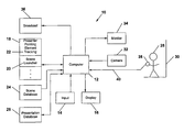
- FIG. 1 An exemplary system 10 in which a scene launcher system and method in accordance with the present invention may be implemented is illustrated in, and will be described with reference to, the schematic block diagram of FIG. 1 .
- the present invention may be implemented in a conventional computer system 12 , such as a single general purpose computer or a plurality of such computers networked or otherwise coupled together to perform the functions to be described herein.
- the present invention may be implemented in the conventional computer systems currently used in television operations to generate, define, and/or present, either for recording or for live broadcast, video or multi-media presentations including computer generated or other scenes in which an on-screen presenter appears.
- the computer system 12 may be provided with conventional input devices 14 , such as a keyboard, mouse, etc., and display devices 16 , such as a computer monitor, to allow an operator of the system to interact with the computer programs implemented on the computer 12 to generate, define, and control presentation of a video or multi-media presentation as described herein.
- input devices 14 such as a keyboard, mouse, etc.
- display devices 16 such as a computer monitor
- the memory 18 is provided as part of, or accessible by, the computer system 12 .
- the memory 18 e.g., including disk memory, RAM, and/or ROM, etc., holds the various computer programs that are run on the computer system 12 to implement a scene launcher system and method in accordance with the present invention.
- Such software includes the scene launcher software 20 itself, which, as will be described in more detail below, includes graphical user interface software for defining presentation scenes in a build mode of operation, as well as software for controlling the launching of scenes by an on-screen presenter in a non-linear manner during the presentation of the presentation.
- the present invention preferably also employs software 22 for tracking a pointing element in a video field, e.g., for tracking the position of the hand of an on-screen presenter appearing in the presentation.
- software 22 for tracking a pointing element in a video field e.g., for tracking the position of the hand of an on-screen presenter appearing in the presentation.
- Exemplary systems and methods for tracking a pointing element in a video field in this manner are described, for example, in U.S. Pat. Nos. 5,270,820, 5,699,442, and 6,549,659, the details of which are incorporated herein by reference.
- Other systems and methods for tracking a pointing element in a video field also may be employed.
- Memory 18 preferably also contains other conventional software programs necessary for general operation of the computer system 12 .
- a system 10 in accordance with the present invention is used to generate and present a video presentation composed of a series of scenes in which an on-screen presenter appears.
- the various scenes forming the presentation may be generated using computer graphics generation and other video generation techniques in a conventional manner and stored, e.g., in a scene database 24 .
- the scenes forming the presentation may be conventional substantially two-dimensional background scenes, in which the presenter appears in front of the scene elements, or more three-dimensional scenes, in which scene objects may appear both behind and in front of the presenter.
- a system and method for generating three-dimensional scenes of this type is described, for example, in U.S. Pat. No.
- an on-screen presenter 28 is positioned in front of a screen 30 having a pre-selected background color.
- a video image of the presenter 28 in front of the background color screen 30 is obtained in a conventional manner using a conventional video camera 32 and is provided, in digital format (e.g., using conventional analog-to-digital video conversion), to the computer system 12 .
- the video image of the presenter 28 in front of the background screen 30 is combined with video scenes by replacing picture elements (pixels) of the video image of the presenter 28 in front of the screen 30 having the background screen color with corresponding pixels of a video scene.
- the resulting combined video image therefore, shows the presenter 28 in front of or as part of the scene.
- This combined image may be provided as a feedback to the presenter 28 on a conventional video monitor 34 , positioned in the field of view of the presenter 28 , so that the presenter 28 may coordinate his movements and positions with the scene in which the presenter 28 appears.
- This combined video image also may be broadcast 36 in a conventional manner, or recorded for broadcast at a later time.
- the video image of the on-screen presenter 28 in front of the background color screen 30 preferably also is analyzed by the computer 12 using the pointing element tracking software 22 to track the position of a pointing element, e.g., the presenter's hand, in the video image field.
- a communication device 38 also is provided to the presenter 28 , whereby the presenter 28 may send a signal to the computer system 12 while the presenter 28 appears on-screen as part of the presentation.
- the communication device 38 may be implemented, for example, as a hand-held device having one or more buttons.
- the communication device may also, or alternatively, include a foot pedal or other foot operated device.
- the communication device 38 may be coupled via a wired or wireless connection 40 to the computer system 12 .
- An exemplary method for defining the scenes of a presentation in which an on-screen presenter is able to control the sequence of displayed scenes forming the presentation in a non-linear manner using a scene launcher method in accordance with the present invention now will be described in detail with reference to the flow chart diagram 42 of FIG. 2 and the exemplary screen shots which follow in FIGS. 3-5 .
- an operator of the system employs a graphical user interface to select or define the scenes which will form the presentation, to define and establish launch areas within those scenes, and to associate destination scenes with each such defined launch area.
- An exemplary graphical user interface 46 for providing the build mode functionality described to an operator of the system is illustrated in the screen shots presented in FIGS. 3-5 .
- the operator first selects 48 or defines a first or initial scene for the presentation.
- the scene may be selected 48 , for example, from available scenes stored in the scene database 24 .
- the first scene 50 may be a computer or otherwise generated digital still or video image of a geographic area over which weather information will be presented as part of a weather report presentation.
- Each launch area may be defined by the operator, for example, by using the graphical user interface 46 to enter information 52 defining a position of a center of the launch area in the scene, e.g., as X and Y coordinates in the scene, or, for a geographical scene, as a lat./lon. coordinate, and the size of the launch area.
- the operator preferably may use an input device 14 such as a mouse and a conventional click and drag operation to locate and define the size of each launch area in the displayed scene.
- An exemplary launch area 54 in the first scene 50 as defined in this manner is illustrated in the exemplary screen shot of FIG. 3 . It should be noted that each launch area thus defined may have any desired shape, size, and location, and each of these launch area parameters may be user definable.
- an indicator icon or flip book For each launch area defined within a scene an indicator icon or flip book preferably is defined or assigned 56 thereto.
- an indicator flip book or icon preferably will appear on the presenter's monitor 34 , thereby giving a visual indication that a launch area is located there and is being indicated by the on-screen presenter.
- the characteristics of the indicator flip book or icon may be defined by an operator using the graphical user interface 46 which preferably allows the operator to enter or select the appropriate parameters 58 defining the indicator icon or flip book, as illustrated, for example, in the exemplary screen shot of FIG. 3 .
- a destination scene is defined 60 or selected and associated therewith.
- the destination scene is the scene that will be launched, i.e., that will come up to replace the current scene in which the on-screen presenter appears, when that launch area is selected by a presenter in the manner to be described in more detail below.
- the destination scene associated with each launch area may be defined, e.g., as an address location 62 of the destination scene in the system memory, e.g., in the scene database 24 , using the graphical user interface 46 as illustrated, e.g., in the exemplary screen shot of FIG. 4 .
- Each destination background scene may include, for example, a computer or otherwise generated still or video scene, e.g., another scene in a weather report presentation.
- the build mode 44 procedure just described may be repeated 64 for one or more of the destination scenes from the first scene, to create launch areas with associated indicator icons or flip books and subsequent destination scenes for each thus defined launch area in the scenes.
- the collection of scenes and launch areas thus defined may be saved 66 , e.g., in the presentation database 26 , for recall and use during presentation of the presentation.
- each of the individual scenes and the collection of launch areas and destination scenes associated with that scene may be saved as a favorite 68 for easy recall at a later time using the graphical user interface 46 , as illustrated, for example, in the exemplary screen shot of FIG. 5 .
- the on-screen presenter 28 is positioned in front of the background color screen 30 and is provided with the communication device 38 as described earlier.
- the presentation scene definitions, as defined in the build mode 44 are retrieved from the presentation database 26 and the first or initial scene in the presentation is displayed with the on-screen presenter 28 appearing in front of or within the scene by combining the image of the presenter 28 in front of the background color screen 30 as provided by the video camera 32 with the first scene image in the conventional manner described above.
- This combined image is provided to the on-screen presenter 28 on the monitor 34 so that the presenter 28 can coordinate his movements and position in real space with his position in the scene using the feedback provided.
- the movement of a pointing element, e.g., the on-screen presenter's hand, controlled by the on-screen presenter 28 , within the video image obtained by the camera 32 is tracked, e.g., using the pointing element tracking software 22 described above.
- the presenter 28 moves 74 the pointing element, e.g., his hand, into an area in space corresponding to a launch area as defined in the displayed scene.
- the system provides feedback 76 to the presenter 28 on the monitor 34 by showing thereon the associated indicator icon or flip book when the presenter has positioned the pointing element in the appropriate position corresponding to a launch area.
- the presenter With the pointing element positioned in a position corresponding to a launch area, the presenter indicates 78 that a scene change is to be made using the communication device 38 , e.g., by depressing a button on the communication device to initiate a scene change signal that is provided to the computer system 12 .
- the system launches 80 a new scene, i.e., a new scene comes up to replace the existing scene.
- a new scene comes up to replace the existing scene.
- the presenter 28 now appears in the new scene selected.
- the specific scene that is launched 80 depends on the particular one of the plurality of launch areas defined in the previous scene which the on-screen presenter 28 was indicating at the time that the communication device 38 was operated to indicate that a scene change is to be made.
- the on-screen presenter 28 is able to control both the timing of scene changes as well as the sequence of scene changes in a non-linear manner.
- the process of indicating a launch area by positioning 74 a pointing element in the video field and indicating 78 that a scene change is to be made may be repeated by the presenter 28 for each currently displayed scene for which launch areas and their associated destination scenes have been defined as described above.
- the system may also allow the on-screen presenter 28 to return to the last previously viewed scene by indicating such a scene change is desired using the communication device 38 , e.g., by pushing the appropriate button on the communication device 38 .
- the on-screen presenter may have full control of the scene sequence and presentation flow throughout the duration of the presentation until the end of the presentation 84 .
- the presentation thus provided using a scene launcher method in accordance with the present invention may be broadcast 36 or otherwise transmitted live to viewers and/or recorded or otherwise saved for future viewing.
Abstract
Description
Claims (18)
Priority Applications (3)
| Application Number | Priority Date | Filing Date | Title |
|---|---|---|---|
| US11/110,356 US7800582B1 (en) | 2004-04-21 | 2005-04-20 | Scene launcher system and method for weather report presentations and the like |
| US12/393,232 US8462108B2 (en) | 2004-04-21 | 2009-02-26 | Scene launcher system and method using geographically defined launch areas |
| US12/872,518 US8669936B2 (en) | 2004-04-21 | 2010-08-31 | System and method for presenting a dynamically ordered presentation |
Applications Claiming Priority (2)
| Application Number | Priority Date | Filing Date | Title |
|---|---|---|---|
| US56418104P | 2004-04-21 | 2004-04-21 | |
| US11/110,356 US7800582B1 (en) | 2004-04-21 | 2005-04-20 | Scene launcher system and method for weather report presentations and the like |
Related Child Applications (2)
| Application Number | Title | Priority Date | Filing Date |
|---|---|---|---|
| US12/393,232 Continuation-In-Part US8462108B2 (en) | 2004-04-21 | 2009-02-26 | Scene launcher system and method using geographically defined launch areas |
| US12/872,518 Continuation-In-Part US8669936B2 (en) | 2004-04-21 | 2010-08-31 | System and method for presenting a dynamically ordered presentation |
Publications (1)
| Publication Number | Publication Date |
|---|---|
| US7800582B1 true US7800582B1 (en) | 2010-09-21 |
Family
ID=42733919
Family Applications (1)
| Application Number | Title | Priority Date | Filing Date |
|---|---|---|---|
| US11/110,356 Expired - Fee Related US7800582B1 (en) | 2004-04-21 | 2005-04-20 | Scene launcher system and method for weather report presentations and the like |
Country Status (1)
| Country | Link |
|---|---|
| US (1) | US7800582B1 (en) |
Cited By (3)
| Publication number | Priority date | Publication date | Assignee | Title |
|---|---|---|---|---|
| US8330730B1 (en) * | 2007-09-04 | 2012-12-11 | Imaging Systems Technology, Inc. | Calibrating of interactive touch system for image compositing |
| CN103383599A (en) * | 2012-05-02 | 2013-11-06 | 祁欣 | Special keyboard of typing in weather phenomenon symbols |
| US9191665B1 (en) * | 2007-06-19 | 2015-11-17 | Imaging Systems Technology, Inc. | Touch system for blue screen |
Citations (36)
| Publication number | Priority date | Publication date | Assignee | Title |
|---|---|---|---|---|
| US5185526A (en) * | 1990-10-31 | 1993-02-09 | Grumman Aerospace Corporation | Optical scene generator for testing infrared detector modules |
| US5250929A (en) * | 1991-07-29 | 1993-10-05 | Conference Communications, Inc. | Interactive overlay-driven computer display system |
| US5345313A (en) * | 1992-02-25 | 1994-09-06 | Imageware Software, Inc | Image editing system for taking a background and inserting part of an image therein |
| US5404447A (en) * | 1991-12-30 | 1995-04-04 | Apple Computer, Inc. | Apparatus for manipulating image pixel streams to generate an output image pixel stream in response to a selected mode |
| US5583972A (en) * | 1993-08-02 | 1996-12-10 | Miller; Richard L. | 3-D weather display and weathercast system |
| US5886747A (en) * | 1996-02-01 | 1999-03-23 | Rt-Set | Prompting guide for chroma keying |
| US6052648A (en) * | 1996-04-12 | 2000-04-18 | Earthwatch Communications, Inc. | Method and system for display of weather-related information |
| US20010003846A1 (en) * | 1999-05-19 | 2001-06-14 | New Horizons Telecasting, Inc. | Encapsulated, streaming media automation and distribution system |
| US20010035976A1 (en) * | 2000-02-15 | 2001-11-01 | Andrew Poon | Method and system for online presentations of writings and line drawings |
| US6339747B1 (en) * | 2000-04-05 | 2002-01-15 | Weather Central, Inc. | Weather tracking and display system and method |
| US20020008692A1 (en) * | 1998-07-30 | 2002-01-24 | Katsuyuki Omura | Electronic blackboard system |
| US6421042B1 (en) * | 1998-06-09 | 2002-07-16 | Ricoh Company, Ltd. | Coordinate position inputting/detecting device, a method for inputting/detecting the coordinate position, and a display board system |
| US6512507B1 (en) * | 1998-03-31 | 2003-01-28 | Seiko Epson Corporation | Pointing position detection device, presentation system, and method, and computer-readable medium |
| US20030034999A1 (en) * | 2001-05-31 | 2003-02-20 | Mindspeak, Llc | Enhancing interactive presentations |
| US20030086605A1 (en) * | 2001-11-08 | 2003-05-08 | Doner John R. | Compression method for aviation weather products |
| US6606127B1 (en) * | 1999-06-10 | 2003-08-12 | Enseo, Inc. | System and method for synchronizing, storing and accurately reproducing video signals |
| US6616281B1 (en) * | 2002-08-07 | 2003-09-09 | Imatte, Inc. | Visible-invisible background prompter |
| US20030206182A1 (en) * | 2001-07-20 | 2003-11-06 | Weather Central, Inc. Wisconsin Corporation | Synchronized graphical information and time-lapse photography for weather presentations and the like |
| US20030222890A1 (en) * | 2002-05-31 | 2003-12-04 | David Salesin | System and method for adaptable presentations |
| US20040008185A1 (en) * | 2002-03-29 | 2004-01-15 | Mitac International Corp. | Data processing device, presentation device, and projection method for presentation |
| US20040012619A1 (en) * | 2002-07-22 | 2004-01-22 | International Business Machines Corporation | Method and system for displaying descriptive information associated with a hot video object |
| US20040090424A1 (en) * | 2002-11-05 | 2004-05-13 | Hurley Gerald C. | Integrated information presentation system with enviromental controls |
| US6741755B1 (en) * | 2000-12-22 | 2004-05-25 | Microsoft Corporation | System and method providing mixture-based determination of opacity |
| US6750803B2 (en) * | 2001-02-23 | 2004-06-15 | Interlink Electronics, Inc. | Transformer remote control |
| US6766066B2 (en) * | 2000-03-31 | 2004-07-20 | Seiko Epson Corporation | Detection of pointed position using image processing |
| US20040162675A1 (en) * | 2001-11-01 | 2004-08-19 | Dennis Moon | System presenting meteorological information using a browser interface |
| US20040174434A1 (en) * | 2002-12-18 | 2004-09-09 | Walker Jay S. | Systems and methods for suggesting meta-information to a camera user |
| US20040196363A1 (en) * | 2003-04-01 | 2004-10-07 | Gary Diamond | Video identification verification system |
| US20050110801A1 (en) * | 2003-11-20 | 2005-05-26 | I-Jong Lin | Methods and systems for processing displayed images |
| US20050140832A1 (en) * | 2003-12-31 | 2005-06-30 | Ron Goldman | Laser projection display |
| US6961061B1 (en) * | 2002-04-19 | 2005-11-01 | Weather Central, Inc. | Forecast weather video presentation system and method |
| US20060013473A1 (en) * | 1997-04-15 | 2006-01-19 | Vulcan Patents Llc | Data processing system and method |
| US7134078B2 (en) * | 2001-04-18 | 2006-11-07 | Nokia Corporation | Handheld portable user device and method for the presentation of images |
| US20070106950A1 (en) * | 2004-04-01 | 2007-05-10 | Hutchinson Ian G | Portable presentation system and methods for use therewith |
| US7250945B1 (en) * | 2001-09-07 | 2007-07-31 | Scapeware3D, Llc | Three dimensional weather forecast rendering |
| US7349830B2 (en) * | 2003-11-20 | 2008-03-25 | Microsoft Corporation | Weather profiles |
-
2005
- 2005-04-20 US US11/110,356 patent/US7800582B1/en not_active Expired - Fee Related
Patent Citations (40)
| Publication number | Priority date | Publication date | Assignee | Title |
|---|---|---|---|---|
| US5185526A (en) * | 1990-10-31 | 1993-02-09 | Grumman Aerospace Corporation | Optical scene generator for testing infrared detector modules |
| US5250929A (en) * | 1991-07-29 | 1993-10-05 | Conference Communications, Inc. | Interactive overlay-driven computer display system |
| US5404447A (en) * | 1991-12-30 | 1995-04-04 | Apple Computer, Inc. | Apparatus for manipulating image pixel streams to generate an output image pixel stream in response to a selected mode |
| US5345313A (en) * | 1992-02-25 | 1994-09-06 | Imageware Software, Inc | Image editing system for taking a background and inserting part of an image therein |
| US5583972A (en) * | 1993-08-02 | 1996-12-10 | Miller; Richard L. | 3-D weather display and weathercast system |
| US5886747A (en) * | 1996-02-01 | 1999-03-23 | Rt-Set | Prompting guide for chroma keying |
| US6052648A (en) * | 1996-04-12 | 2000-04-18 | Earthwatch Communications, Inc. | Method and system for display of weather-related information |
| US20060013473A1 (en) * | 1997-04-15 | 2006-01-19 | Vulcan Patents Llc | Data processing system and method |
| US6512507B1 (en) * | 1998-03-31 | 2003-01-28 | Seiko Epson Corporation | Pointing position detection device, presentation system, and method, and computer-readable medium |
| US6421042B1 (en) * | 1998-06-09 | 2002-07-16 | Ricoh Company, Ltd. | Coordinate position inputting/detecting device, a method for inputting/detecting the coordinate position, and a display board system |
| US6760009B2 (en) * | 1998-06-09 | 2004-07-06 | Ricoh Company, Ltd. | Coordinate position inputting/detecting device, a method for inputting/detecting the coordinate position, and a display board system |
| US20020008692A1 (en) * | 1998-07-30 | 2002-01-24 | Katsuyuki Omura | Electronic blackboard system |
| US20050060759A1 (en) * | 1999-05-19 | 2005-03-17 | New Horizons Telecasting, Inc. | Encapsulated, streaming media automation and distribution system |
| US20010003846A1 (en) * | 1999-05-19 | 2001-06-14 | New Horizons Telecasting, Inc. | Encapsulated, streaming media automation and distribution system |
| US6606127B1 (en) * | 1999-06-10 | 2003-08-12 | Enseo, Inc. | System and method for synchronizing, storing and accurately reproducing video signals |
| US20010035976A1 (en) * | 2000-02-15 | 2001-11-01 | Andrew Poon | Method and system for online presentations of writings and line drawings |
| US6766066B2 (en) * | 2000-03-31 | 2004-07-20 | Seiko Epson Corporation | Detection of pointed position using image processing |
| US6339747B1 (en) * | 2000-04-05 | 2002-01-15 | Weather Central, Inc. | Weather tracking and display system and method |
| US6741755B1 (en) * | 2000-12-22 | 2004-05-25 | Microsoft Corporation | System and method providing mixture-based determination of opacity |
| US6750803B2 (en) * | 2001-02-23 | 2004-06-15 | Interlink Electronics, Inc. | Transformer remote control |
| US7134078B2 (en) * | 2001-04-18 | 2006-11-07 | Nokia Corporation | Handheld portable user device and method for the presentation of images |
| US20030034999A1 (en) * | 2001-05-31 | 2003-02-20 | Mindspeak, Llc | Enhancing interactive presentations |
| US20030206182A1 (en) * | 2001-07-20 | 2003-11-06 | Weather Central, Inc. Wisconsin Corporation | Synchronized graphical information and time-lapse photography for weather presentations and the like |
| US20060209090A1 (en) * | 2001-07-20 | 2006-09-21 | Kelly Terence F | Synchronized graphical information and time-lapse photography for weather presentations and the like |
| US7250945B1 (en) * | 2001-09-07 | 2007-07-31 | Scapeware3D, Llc | Three dimensional weather forecast rendering |
| US20040162675A1 (en) * | 2001-11-01 | 2004-08-19 | Dennis Moon | System presenting meteorological information using a browser interface |
| US20030086605A1 (en) * | 2001-11-08 | 2003-05-08 | Doner John R. | Compression method for aviation weather products |
| US20040008185A1 (en) * | 2002-03-29 | 2004-01-15 | Mitac International Corp. | Data processing device, presentation device, and projection method for presentation |
| US6961061B1 (en) * | 2002-04-19 | 2005-11-01 | Weather Central, Inc. | Forecast weather video presentation system and method |
| US20060001668A1 (en) * | 2002-04-19 | 2006-01-05 | Johnson Chad W | Forecast weather video presentation system and method |
| US20030222890A1 (en) * | 2002-05-31 | 2003-12-04 | David Salesin | System and method for adaptable presentations |
| US20040012619A1 (en) * | 2002-07-22 | 2004-01-22 | International Business Machines Corporation | Method and system for displaying descriptive information associated with a hot video object |
| US6616281B1 (en) * | 2002-08-07 | 2003-09-09 | Imatte, Inc. | Visible-invisible background prompter |
| US20040090424A1 (en) * | 2002-11-05 | 2004-05-13 | Hurley Gerald C. | Integrated information presentation system with enviromental controls |
| US20040174434A1 (en) * | 2002-12-18 | 2004-09-09 | Walker Jay S. | Systems and methods for suggesting meta-information to a camera user |
| US20040196363A1 (en) * | 2003-04-01 | 2004-10-07 | Gary Diamond | Video identification verification system |
| US20050110801A1 (en) * | 2003-11-20 | 2005-05-26 | I-Jong Lin | Methods and systems for processing displayed images |
| US7349830B2 (en) * | 2003-11-20 | 2008-03-25 | Microsoft Corporation | Weather profiles |
| US20050140832A1 (en) * | 2003-12-31 | 2005-06-30 | Ron Goldman | Laser projection display |
| US20070106950A1 (en) * | 2004-04-01 | 2007-05-10 | Hutchinson Ian G | Portable presentation system and methods for use therewith |
Cited By (3)
| Publication number | Priority date | Publication date | Assignee | Title |
|---|---|---|---|---|
| US9191665B1 (en) * | 2007-06-19 | 2015-11-17 | Imaging Systems Technology, Inc. | Touch system for blue screen |
| US8330730B1 (en) * | 2007-09-04 | 2012-12-11 | Imaging Systems Technology, Inc. | Calibrating of interactive touch system for image compositing |
| CN103383599A (en) * | 2012-05-02 | 2013-11-06 | 祁欣 | Special keyboard of typing in weather phenomenon symbols |
Similar Documents
| Publication | Publication Date | Title |
|---|---|---|
| US8665375B2 (en) | Apparatus and method for tracking the location of a pointing element in a cropped video field | |
| US8049721B2 (en) | Pointer light tracking method, program, and recording medium thereof | |
| US10304238B2 (en) | Geo-located activity visualisation, editing and sharing | |
| US6339747B1 (en) | Weather tracking and display system and method | |
| JP4901040B2 (en) | Marking moving objects in video streams | |
| US7584054B2 (en) | System and method for displaying storm tracks | |
| US7673246B2 (en) | Image information processing apparatus and method, virtual space presentation apparatus, information administration apparatus, and control methods thereof | |
| US20100171758A1 (en) | Method and system for generating augmented reality signals | |
| US10230925B2 (en) | Systems and methods for processing and providing terrestrial and/or space-based earth observation video | |
| US8223063B2 (en) | System and method for presenting wind speed information in a planar representation | |
| US20080109729A1 (en) | Method and apparatus for control and processing of video images | |
| JP2009535734A (en) | Geographic information system and associated method for displaying a three-dimensional geospatial image with a reference sign | |
| US20240078703A1 (en) | Personalized scene image processing method, apparatus and storage medium | |
| CN112927349B (en) | Three-dimensional virtual special effect generation method and device, computer equipment and storage medium | |
| CN106464773A (en) | Augmented reality apparatus and method | |
| US9773523B2 (en) | Apparatus, method and computer program | |
| US20160381290A1 (en) | Apparatus, method and computer program | |
| US7800582B1 (en) | Scene launcher system and method for weather report presentations and the like | |
| US8669936B2 (en) | System and method for presenting a dynamically ordered presentation | |
| JP3410703B2 (en) | Image display method | |
| US8462108B2 (en) | Scene launcher system and method using geographically defined launch areas | |
| US11360639B2 (en) | Media content planning system | |
| CN109117053B (en) | Dynamic display method, device and equipment for interface content | |
| CN113906731A (en) | Video processing method and device | |
| CN111277866B (en) | Method and related device for controlling VR video playing |
Legal Events
| Date | Code | Title | Description |
|---|---|---|---|
| AS | Assignment |
Owner name: WEATHER CENTRAL, INC., WISCONSIN Free format text: ASSIGNMENT OF ASSIGNORS INTEREST;ASSIGNORS:MOORE, JOHN S.;MARSH, VICTOR W.;ZIMMERMAN, BENJAMIN T.;SIGNING DATES FROM 20051114 TO 20051116;REEL/FRAME:017787/0934 |
|
| STCF | Information on status: patent grant |
Free format text: PATENTED CASE |
|
| AS | Assignment |
Owner name: WEATHER CENTRAL, LLC, WISCONSIN Free format text: ASSIGNMENT OF ASSIGNORS INTEREST;ASSIGNOR:WEATHER CENTRAL, INC.;REEL/FRAME:028452/0721 Effective date: 20090730 |
|
| AS | Assignment |
Owner name: WEATHER CENTRAL, LP, WISCONSIN Free format text: CHANGE OF NAME;ASSIGNOR:WEATHER CENTRAL, LLC;REEL/FRAME:028545/0284 Effective date: 20110113 |
|
| AS | Assignment |
Owner name: DEUTSCHE BANK TRUST COMPANY AMERICAS, AS COLLATERA Free format text: SECURITY AGREEMENT;ASSIGNOR:WEATHER CENTRAL, LP;REEL/FRAME:029177/0217 Effective date: 20121005 |
|
| AS | Assignment |
Owner name: DEUTSCHE BANK TRUST COMPANY AMERICAS, AS COLLATERA Free format text: SECURITY AGREEMENT;ASSIGNORS:THE WEATHER CHANNEL, LLC;WSI CORPORATION;WEATHER CENTRAL, LP;AND OTHERS;REEL/FRAME:030698/0610 Effective date: 20130626 |
|
| FEPP | Fee payment procedure |
Free format text: PAT HOLDER NO LONGER CLAIMS SMALL ENTITY STATUS, ENTITY STATUS SET TO UNDISCOUNTED (ORIGINAL EVENT CODE: STOL); ENTITY STATUS OF PATENT OWNER: LARGE ENTITY |
|
| REFU | Refund |
Free format text: REFUND - SURCHARGE, PETITION TO ACCEPT PYMT AFTER EXP, UNINTENTIONAL (ORIGINAL EVENT CODE: R2551); ENTITY STATUS OF PATENT OWNER: LARGE ENTITY |
|
| AS | Assignment |
Owner name: WSI CORPORATION, MASSACHUSETTS Free format text: MERGER;ASSIGNOR:WEATHER CENTRAL, LP;REEL/FRAME:031995/0694 Effective date: 20131213 |
|
| FPAY | Fee payment |
Year of fee payment: 4 |
|
| AS | Assignment |
Owner name: DEUTSCHE BANK AG NEW YORK BRANCH, AS SUCCESSOR AGE Free format text: NOTICE OF SUCCESSION OF AGENCY (FIRST LIEN);ASSIGNOR:DEUTSCHE BANK TRUST COMPANY AMERICAS;REEL/FRAME:035841/0001 Effective date: 20150603 |
|
| AS | Assignment |
Owner name: WSI CORPORATION, MASSACHUSETTS Free format text: RELEASE BY SECURED PARTY;ASSIGNOR:DEUTSCHE BANK AG NEW YORK BRANCH, AS ADMINISTRATIVE AGENT AND COLLATERAL AGENT;REEL/FRAME:038081/0001 Effective date: 20160129 Owner name: THE WEATHER CHANNEL, INC., GEORGIA Free format text: RELEASE BY SECURED PARTY;ASSIGNOR:DEUTSCHE BANK AG NEW YORK BRANCH, AS ADMINISTRATIVE AGENT AND COLLATERAL AGENT;REEL/FRAME:038081/0001 Effective date: 20160129 Owner name: ENTERPRISE ELECTRONICS CORPORATION, ALABAMA Free format text: RELEASE BY SECURED PARTY;ASSIGNOR:DEUTSCHE BANK AG NEW YORK BRANCH, AS ADMINISTRATIVE AGENT AND COLLATERAL AGENT;REEL/FRAME:038081/0001 Effective date: 20160129 Owner name: THE WEATHER CHANNEL, LLC, GEORGIA Free format text: RELEASE BY SECURED PARTY;ASSIGNOR:DEUTSCHE BANK AG NEW YORK BRANCH, AS ADMINISTRATIVE AGENT AND COLLATERAL AGENT;REEL/FRAME:038081/0001 Effective date: 20160129 Owner name: WSI CORPORATION, MASSACHUSETTS Free format text: RELEASE BY SECURED PARTY;ASSIGNOR:DEUTSCHE BANK TRUST COMPANY AMERICAS, AS ADMINISTRATIVE AGENT AND COLLATERAL AGENT;REEL/FRAME:038080/0971 Effective date: 20160129 Owner name: MYWEATHER, LLC, CALIFORNIA Free format text: RELEASE BY SECURED PARTY;ASSIGNOR:DEUTSCHE BANK TRUST COMPANY AMERICAS, AS ADMINISTRATIVE AGENT AND COLLATERAL AGENT;REEL/FRAME:038080/0971 Effective date: 20160129 Owner name: WEATHER CENTRAL, LP, WISCONSIN Free format text: RELEASE BY SECURED PARTY;ASSIGNOR:DEUTSCHE BANK TRUST COMPANY AMERICAS, AS ADMINISTRATIVE AGENT AND COLLATERAL AGENT;REEL/FRAME:038080/0971 Effective date: 20160129 Owner name: THE WEATHER CHANNEL, LLC, GEORGIA Free format text: RELEASE BY SECURED PARTY;ASSIGNOR:DEUTSCHE BANK TRUST COMPANY AMERICAS, AS ADMINISTRATIVE AGENT AND COLLATERAL AGENT;REEL/FRAME:038080/0971 Effective date: 20160129 |
|
| AS | Assignment |
Owner name: TWC PATENT TRUST LLT, VERMONT Free format text: ASSIGNMENT OF ASSIGNORS INTEREST;ASSIGNOR:WSI CORPORATION;REEL/FRAME:038361/0199 Effective date: 20160129 |
|
| FEPP | Fee payment procedure |
Free format text: PAT HOLDER CLAIMS SMALL ENTITY STATUS, ENTITY STATUS SET TO SMALL (ORIGINAL EVENT CODE: LTOS); ENTITY STATUS OF PATENT OWNER: LARGE ENTITY |
|
| FEPP | Fee payment procedure |
Free format text: ENTITY STATUS SET TO UNDISCOUNTED (ORIGINAL EVENT CODE: BIG.) |
|
| MAFP | Maintenance fee payment |
Free format text: PAYMENT OF MAINTENANCE FEE, 8TH YEAR, LARGE ENTITY (ORIGINAL EVENT CODE: M1552) Year of fee payment: 8 |
|
| AS | Assignment |
Owner name: DTN, LLC, NEBRASKA Free format text: ASSIGNMENT OF ASSIGNORS INTEREST;ASSIGNOR:TWC PATENT TRUST LLT;REEL/FRAME:050615/0683 Effective date: 20190930 |
|
| FEPP | Fee payment procedure |
Free format text: MAINTENANCE FEE REMINDER MAILED (ORIGINAL EVENT CODE: REM.); ENTITY STATUS OF PATENT OWNER: LARGE ENTITY |
|
| LAPS | Lapse for failure to pay maintenance fees |
Free format text: PATENT EXPIRED FOR FAILURE TO PAY MAINTENANCE FEES (ORIGINAL EVENT CODE: EXP.); ENTITY STATUS OF PATENT OWNER: LARGE ENTITY |
|
| STCH | Information on status: patent discontinuation |
Free format text: PATENT EXPIRED DUE TO NONPAYMENT OF MAINTENANCE FEES UNDER 37 CFR 1.362 |
|
| FP | Lapsed due to failure to pay maintenance fee |
Effective date: 20220921 |