US7804896B2 - Content adaptive noise reduction filtering for image signals - Google Patents

Content adaptive noise reduction filtering for image signals Download PDF

Info

Publication number
US7804896B2
US7804896B2 US11/230,148 US23014805A US7804896B2 US 7804896 B2 US7804896 B2 US 7804896B2 US 23014805 A US23014805 A US 23014805A US 7804896 B2 US7804896 B2 US 7804896B2
Authority
US
United States
Prior art keywords
value
target pixel
pixel
noise reduction
reduction circuit
Prior art date
Legal status (The legal status is an assumption and is not a legal conclusion. Google has not performed a legal analysis and makes no representation as to the accuracy of the status listed.)
Expired - Fee Related, expires
Application number
US11/230,148
Other versions
US20070064792A1 (en
Inventor
Yi-Jen Chiu
Louis Lippincott
Current Assignee (The listed assignees may be inaccurate. Google has not performed a legal analysis and makes no representation or warranty as to the accuracy of the list.)
Intel Corp
Original Assignee
Intel Corp
Priority date (The priority date is an assumption and is not a legal conclusion. Google has not performed a legal analysis and makes no representation as to the accuracy of the date listed.)
Filing date
Publication date
Application filed by Intel Corp filed Critical Intel Corp
Priority to US11/230,148 priority Critical patent/US7804896B2/en
Assigned to INTEL CORPORATION reassignment INTEL CORPORATION ASSIGNMENT OF ASSIGNORS INTEREST (SEE DOCUMENT FOR DETAILS). Assignors: CHIU, YI-JEN, KIPPINCOTT, LOUIS
Priority to PCT/US2006/029528 priority patent/WO2007040765A1/en
Priority to KR1020087006603A priority patent/KR101031438B1/en
Priority to CNB2006101399052A priority patent/CN100512376C/en
Publication of US20070064792A1 publication Critical patent/US20070064792A1/en
Priority to US12/862,175 priority patent/US8218082B2/en
Application granted granted Critical
Publication of US7804896B2 publication Critical patent/US7804896B2/en
Expired - Fee Related legal-status Critical Current
Adjusted expiration legal-status Critical

Links

Images

Classifications

    • G06T5/70
    • HELECTRICITY
    • H04ELECTRIC COMMUNICATION TECHNIQUE
    • H04NPICTORIAL COMMUNICATION, e.g. TELEVISION
    • H04N5/00Details of television systems
    • H04N5/14Picture signal circuitry for video frequency region
    • H04N5/21Circuitry for suppressing or minimising disturbance, e.g. moiré or halo
    • GPHYSICS
    • G06COMPUTING; CALCULATING OR COUNTING
    • G06TIMAGE DATA PROCESSING OR GENERATION, IN GENERAL
    • G06T5/00Image enhancement or restoration
    • G06T5/20Image enhancement or restoration by the use of local operators
    • GPHYSICS
    • G06COMPUTING; CALCULATING OR COUNTING
    • G06TIMAGE DATA PROCESSING OR GENERATION, IN GENERAL
    • G06T7/00Image analysis
    • G06T7/10Segmentation; Edge detection
    • G06T7/13Edge detection
    • HELECTRICITY
    • H04ELECTRIC COMMUNICATION TECHNIQUE
    • H04BTRANSMISSION
    • H04B1/00Details of transmission systems, not covered by a single one of groups H04B3/00 - H04B13/00; Details of transmission systems not characterised by the medium used for transmission
    • H04B1/66Details of transmission systems, not covered by a single one of groups H04B3/00 - H04B13/00; Details of transmission systems not characterised by the medium used for transmission for reducing bandwidth of signals; for improving efficiency of transmission
    • HELECTRICITY
    • H04ELECTRIC COMMUNICATION TECHNIQUE
    • H04NPICTORIAL COMMUNICATION, e.g. TELEVISION
    • H04N19/00Methods or arrangements for coding, decoding, compressing or decompressing digital video signals
    • H04N19/10Methods or arrangements for coding, decoding, compressing or decompressing digital video signals using adaptive coding
    • H04N19/102Methods or arrangements for coding, decoding, compressing or decompressing digital video signals using adaptive coding characterised by the element, parameter or selection affected or controlled by the adaptive coding
    • H04N19/117Filters, e.g. for pre-processing or post-processing
    • HELECTRICITY
    • H04ELECTRIC COMMUNICATION TECHNIQUE
    • H04NPICTORIAL COMMUNICATION, e.g. TELEVISION
    • H04N19/00Methods or arrangements for coding, decoding, compressing or decompressing digital video signals
    • H04N19/10Methods or arrangements for coding, decoding, compressing or decompressing digital video signals using adaptive coding
    • H04N19/134Methods or arrangements for coding, decoding, compressing or decompressing digital video signals using adaptive coding characterised by the element, parameter or criterion affecting or controlling the adaptive coding
    • H04N19/136Incoming video signal characteristics or properties
    • H04N19/14Coding unit complexity, e.g. amount of activity or edge presence estimation
    • HELECTRICITY
    • H04ELECTRIC COMMUNICATION TECHNIQUE
    • H04NPICTORIAL COMMUNICATION, e.g. TELEVISION
    • H04N19/00Methods or arrangements for coding, decoding, compressing or decompressing digital video signals
    • H04N19/85Methods or arrangements for coding, decoding, compressing or decompressing digital video signals using pre-processing or post-processing specially adapted for video compression
    • H04N19/86Methods or arrangements for coding, decoding, compressing or decompressing digital video signals using pre-processing or post-processing specially adapted for video compression involving reduction of coding artifacts, e.g. of blockiness
    • GPHYSICS
    • G06COMPUTING; CALCULATING OR COUNTING
    • G06TIMAGE DATA PROCESSING OR GENERATION, IN GENERAL
    • G06T2207/00Indexing scheme for image analysis or image enhancement
    • G06T2207/10Image acquisition modality
    • G06T2207/10016Video; Image sequence
    • GPHYSICS
    • G06COMPUTING; CALCULATING OR COUNTING
    • G06TIMAGE DATA PROCESSING OR GENERATION, IN GENERAL
    • G06T2207/00Indexing scheme for image analysis or image enhancement
    • G06T2207/20Special algorithmic details
    • G06T2207/20004Adaptive image processing
    • G06T2207/20012Locally adaptive
    • GPHYSICS
    • G06COMPUTING; CALCULATING OR COUNTING
    • G06TIMAGE DATA PROCESSING OR GENERATION, IN GENERAL
    • G06T2207/00Indexing scheme for image analysis or image enhancement
    • G06T2207/20Special algorithmic details
    • G06T2207/20172Image enhancement details
    • G06T2207/20192Edge enhancement; Edge preservation

Definitions

  • Sources of noise include compression encoding/decoding, which may result in various types of artifacts such as block noise, ringing noise, mosquito noise and transform noise.
  • Other sources of noise may include video capture processing, analog-to-digital conversion, and signal transmission.
  • Noise reduction processing may be performed after video signal decompression (decoding) for purposes of image quality improvement, and may also be performed prior to transmission or recording, to avoid wasting bandwidth on transmission/recording of artifacts as well as for quality considerations.
  • noise reduction processing involve low pass filtering of the video signal. Although generally worthwhile to mitigate artifacts, such filtering may also blur the image to some extent, so that noise reduction processing may entail trading off one type of distortion for another. Computational complexity may also be a drawback in noise reduction processing.
  • FIG. 1 is a block diagram of an apparatus which generates a video bitstream from captured images in accordance with some embodiments.
  • FIG. 2 is a block diagram of an apparatus which generates a video display from a video bitstream in accordance with some embodiments.
  • FIG. 3 is a functional block diagram that illustrates some operations of a noise reduction block that is part of the apparatus of FIG. 1 or FIG. 2 .
  • FIG. 4 is a flow chart that illustrates a process performed by the noise reduction block.
  • FIG. 5 schematically illustrates aspects of the process of FIG. 4 .
  • FIG. 6 is a functional block diagram that illustrates some operations of the noise reduction block in some other embodiments.
  • FIGS. 7A and 7B together form a flow chart that illustrates a process that may be performed in connection with the functional arrangement of FIG. 6 .
  • FIG. 8 graphically illustrates an aspect of the process of FIGS. 7A and 7B .
  • FIG. 9 is a functional block diagram that illustrates aspects of noise reduction filtering performed according to still other embodiments in the apparatus of FIG. 2 .
  • FIGS. 10A and 10B together form a flow chart that illustrates a process that may be performed in connection with the functional arrangement of FIG. 9 .
  • FIG. 1 is a block diagram of an apparatus 100 which generates a video bitstream from captured images in accordance with some embodiments.
  • the apparatus 100 includes a video signal capture device 102 such as a digital video camera.
  • the apparatus 100 further includes a pre-processing block 104 which is coupled to the video signal capture device 102 .
  • the pre-processing block 104 performs one or more kinds of pre-processing on the captured video signal provided by the video signal capture device 102 .
  • the pre-processing block 104 may perform one or more different kinds of noise reduction processing as in one of the embodiments described below.
  • the apparatus 100 also includes a compression encoding block 106 which is coupled to the pre-processing block 104 .
  • the compression encoding block 106 may apply compression encoding in accordance with conventional practices to the pre-processed video signal provided by the pre-processing block 104 .
  • the apparatus 100 may include a transmitter 108 coupled to the compression encoding block 106 to transmit the compression encoded video signal in the form of a video signal bitstream over a communication channel which is not separately shown.
  • FIG. 2 is a block diagram of an apparatus 200 which generates a video display from a video bitstream in accordance with some embodiments.
  • the apparatus 200 includes a source 202 of a video signal bitstream.
  • the video signal source 202 may receive a video signal via a communication channel (which is not separately shown) or may reproduce a video signal from a storage medium such as a DVD or a hard disk drive.
  • the video signal source may include a video tuner, a satellite earth station, or a DVD player. It will be assumed that the video signal bitstream represents a video signal that has been compression encoded, e.g., in accordance with one of the MPEG compression standards.
  • the video signal source 202 may operate in accordance with conventional practices.
  • the apparatus 200 also includes a video decoder 204 which is coupled to the video signal source to de-compress the video signal bitstream supplied by the video signal source 202 .
  • the video decoder 204 may operate in accordance with conventional principles, and may tend to produce artifacts in the output video image, subject to amelioration via embodiments to be described below.
  • the apparatus 200 further includes a post-processing block 206 which is coupled to the video decoder 204 .
  • the post-processing block 206 performs one or more kinds of post processing on the decompressed video signal output from the video decoder 204 .
  • the post-processing block 206 may perform one or more different kinds of noise reduction processing as in one or more of the embodiments described below.
  • the apparatus 200 includes a display device 208 , such as a conventional television set or a computer display monitor.
  • the display device 208 displays the video signal that is output from the post-processing block 206 .
  • FIG. 3 is a functional block diagram that illustrates aspects of a noise reduction process performed in the pre-processing block 104 or in the post-processing block 206 in accordance with some embodiments.
  • Block 302 represents the pre-processing block 104 or the post-processing block 206 (or a noise reduction sub-block) receiving an input video signal (e.g., directly or indirectly from the video capturing device 102 , or directly or indirectly from the video decoder 204 ) that is to be subjected to noise reduction processing.
  • Block 304 represents circuitry (specially designed or programmed) provided in accordance with some embodiments to apply a filtering process that may be referred to as a “content adaptive substitute filtering” process.
  • prospective pixel values to be used for filtering are (as indicated by block 306 ) compared with target pixel values and are replaced in some cases to support improved low-pass filtering (indicated by block 308 ). Output of the resulting low-pass filtered video signal is indicated at block 310 .
  • FIG. 4 is a flow chart that illustrates an embodiment of a content adaptive substitute filtering process that may be performed in block 304 ( FIG. 3 ).
  • block 402 represents block 304 receiving the input video signal (e.g., after video capture or after de-compression of a previously compression-encoded video signal).
  • Block 404 represents selection of a target pixel x from the input video signal.
  • the target pixel x is the pixel for which a filtered output value is now to be calculated.
  • the filter output value for each target pixel is determined on the basis of pixel values in a filter support neighborhood area that is a three-pixel-by-three-pixel square centered on the target pixel x.
  • This area may be referred to as NH(x) or, since the total area corresponds to 9 pixels, as NH9(x).
  • a filter support area other than three-pixels-by-three-pixels may be used. For example, filter support areas of four-pixels-by-four-pixels, five-pixels-by-five-pixels, six-pixels-by-six-pixels or seven-pixels-by-seven-pixels may be used in alternative embodiments.
  • TH(x) may be a constant that is used in connection with all target pixels, but in other embodiments, as described below, TH(x) may vary from target pixel to target pixel. In some embodiments, the constant used for TH(x) may be programmable by a user or designer of the apparatus 100 or 200 .
  • the value of neighboring pixel y is replaced with the value of the target pixel x for the purposes of applying a filtering function to calculate an output filtered pixel value for the target pixel. If at 408 it is determined that the absolute value of the difference between the two pixel values is less than TH(x), then the value of the neighboring pixel is not replaced. Following 408 in the latter case, or following 410 , as the case may be, is a decision block 412 , at which it is determined whether there remain any neighboring pixels in NH9(x), which have not been compared with the target pixel.
  • the process of FIG. 4 loops back to 406 for consideration of another neighboring pixel in NH9(x). If such is not the case, the process proceeds to apply a low-pass filter characteristic to generate a filtered output value for the target pixel, as indicated at 414 and as will be discussed further below.
  • FIG. 5 schematically illustrates an example of how the loop 406 - 412 may operate in connection with a particular target pixel x.
  • the original condition of NH(x) is indicated at 502 , with the target pixel x being represented by the solid black pixel at the center of the array shown at 502 .
  • the hollow circles in the array 502 represent neighboring pixels for which the values differ from the value of pixel x (if at all) by less than TH(x).
  • the shaded circles in the array 502 represent neighboring pixels for which the values differ from the value of pixel x by at least TH(x).
  • the values of the latter neighboring pixels are replaced by the value of the target pixel x to form a substitute filter support array SNH(x).
  • the set of pixel values represented by SNH(x) includes the value of the target pixel and “current values” of the neighboring pixels, where the current value of a neighboring pixel is the original value of the pixel if the value has not undergone replacement and is the value of the target pixel if replacement has occurred.
  • outlier pixel values are removed from the filter support area so that more satisfactory filter results may be obtained.
  • the outlier values are each replaced with the target pixel value, so that the number of input values for the filtering function is the same for each target pixel, thereby reducing complexity of hardware implementation. This is in contrast to the known “sigma filter”, in which outlier values are simply discarded, leading to varying numbers of input values and complex implementation.
  • the filter function to be applied to generate the output filtered value for the target pixel x may be defined by the following weight matrix:
  • this two-dimensional matrix may be decomposed into two one dimensional matrices:
  • filter characteristics other than that indicated above may be used in other embodiments. For example, filter characteristics suitable for other sizes of filter support may be used.
  • the output filtered value for the target pixel x may be calculated as follows:
  • w(y) is the value of the weighting matrix at the position of the pixel y ⁇ NH9(x), and ⁇ y ⁇ is the value of that pixel. It will be noted that 16 is the summation over the weighting matrix and 8 is one-half of that summation, the latter term being applied for purposes of rounding.
  • filter support areas may be employed rather than the above-described three-pixel-by-three-pixel filter support area.
  • the output filtered value may be stored, as indicated at 416 in FIG. 4 . It is next determined, at decision block 418 , whether output filtered values have been obtained for all of the target pixels in the image that is being processed. If not, the process of FIG. 4 loops back to 404 . Otherwise the process is complete. It will be appreciated that the content adaptive substitute filter process illustrated in FIG. 4 may be applied to each image represented by the input video signal.
  • the content adaptive substitute filtering arrangement of FIGS. 3-5 may provide improved noise reduction filtering with a low degree of implementation complexity.
  • FIG. 6 is a functional block diagram that illustrates aspects of a noise reduction process performed in the pre-processing block 104 or in the post-processing block 206 in accordance with some other embodiments.
  • operation of the content adaptive substitute filtering may be modified to incorporate adaptation of the substitution threshold amount TH(x) by taking into consideration the presence of edge conditions at the target pixel x.
  • FIG. 6 the functional blocks that were discussed above in connection with FIG. 3 are also present in FIG. 6 , except that blocks 304 ′ and 306 ′ in FIG. 6 reflect capability to modify in the value of TH(x) from target pixel to target pixel.
  • the arrangement of FIG. 6 includes a functional block 602 which performs edge detection processing at each target pixel.
  • FIGS. 7A and 7B together form a flow chart that illustrates an embodiment of an edge-sensitive content adaptive substitute filtering process that may be performed by blocks 602 and 304 ′ of FIG. 6 .
  • the process of FIGS. 7A and 7B may begin with the same blocks 402 and 404 discussed above in connection with FIG. 4 .
  • the process of FIGS. 7A and 7B includes a block 702 at which an edge metric EM(x) is calculated with respect to the target pixel x.
  • the so-called Sobel edge detector may be employed, using the following matrices:
  • an edge-related substitution threshold ETH(x) is calculated to be used (in place of the above described threshold TH(x)) in a content adaptive substitute filtering process to be applied to the target pixel.
  • FIG. 8 graphically illustrates ETH(x). It will be appreciated that with increasing edge strength at the target pixel, the substitution threshold is reduced, so that the amount of filtering at the target pixel may be reduced. If the edge metric EM(x) reaches or exceeds a saturation point EM_s, the substitution threshold is reduced to zero and no filtering occurs at the target pixel. Thus strong edges are preserved unfiltered and blurring due to noise reduction filtering may be reduced.
  • edge detection processes besides the above-described Sobel edge detector may be employed in place of the Sobel edge detector in some embodiments.
  • the Canny edge detector may be used.
  • the balance of the process blocks in the process of FIGS. 7A and 7B may be the same as the blocks described above in connection with FIG. 4 .
  • the illustrations and descriptions of the processes are not intended to imply a fixed order of process stages. Rather, the process stages may be performed in any order that is practicable.
  • edge detection and threshold calculation may be performed for all target pixels in an image before substituting any neighboring pixel values and performing filtering with respect to any target pixel in the image.
  • FIG. 9 is a functional block diagram that illustrates aspects of a noise reduction process performed in the post-processing block 206 in accordance with still other embodiments.
  • determination of the substitution threshold reflects both edge conditions at the target pixel and a degree of quantization previously applied during compression encoding to a now-decoded (decompressed) video signal that is to be filtered for noise reduction purposes.
  • FIG. 9 shows blocks 202 and 204 discussed above in connection with FIG. 2 , blocks 302 and 310 discussed in connection with FIG. 3 and block 602 discussed in connection with FIG. 6 .
  • the content adaptive substitute block (now labeled 304 ′′), and in particular its constituent compare and replace block (now labeled 306 ′′) are also present, with the compare and replace block 306 ′′ having been modified to receive from the video decoder block 204 a signal that indicates a degree of quantization employed in the compression-encoding of the video signal decoded by block 204 .
  • the compare and replace block 306 ′′ generates substitution threshold values based both on edge conditions detected by block 602 and on the signal from the video decoder 204 to indicate the degree of quantization.
  • FIGS. 10A and 10B together form a flow chart that illustrates an embodiment of a decoder-assisted edge-sensitive adaptive substitute filtering process that may be performed by blocks 602 and 304 ′′ of FIG. 9 .
  • the process of FIGS. 10A and 10B may begin with the same block 402 as discussed in connection with FIG. 4 .
  • the compare and replace block 306 ′′ receives from the video decoder 204 a quantization parameter signal QP(x) which increases in proportion to the degree of quantization (coarseness of quantization) that was applied during compression encoding of the video signal decoded by the video decoder 204 .
  • ETH(x) is calculated to be used in a content adaptive substitute filtering process to be applied to the target pixel.
  • K is a pre-determined (and/or programmable) constant. Both K and QP(x) are greater than zero in this example; C and EM(x) are as described in connection with 702 and 704 of FIG. 7A .
  • the degree of filtering that may be performed by block 304 ′′ may increase with the degree of quantization applied to the video signal during compression encoding. This may be desirable, since an increased amount of coding noise may be present where more quantization was applied.
  • edge detection may be omitted or may not be present and/or C may be set to zero, so that the substitution threshold is quantization-adaptive but not edge-related.
  • the edge detection block and/or the content adaptive substitute filtering block, or other blocks herein, may be implemented as application-specific logic circuitry or by one or more programmable processors controlled by software instructions stored in a memory or memories coupled to the processor or processors.

Abstract

A method includes selecting a target pixel and comparing a value of the target pixel with a respective value of each of a plurality of pixels located in an area that includes the target pixel. Further, for each pixel of the plurality of pixels that has a value different by at least a threshold amount from the value of the target pixel, the value of such pixel is replaced by the value of the target pixel. A filter function is applied to a set of pixels which includes the value of the target pixel and current values, after the selective replacement step, of the plurality of pixels.

Description

BACKGROUND
It is known to perform noise reduction processing on video signals to improve perceived image quality by mitigating the effects of noise that typically is present in the video signals. Sources of noise include compression encoding/decoding, which may result in various types of artifacts such as block noise, ringing noise, mosquito noise and transform noise. Other sources of noise may include video capture processing, analog-to-digital conversion, and signal transmission.
Noise reduction processing may be performed after video signal decompression (decoding) for purposes of image quality improvement, and may also be performed prior to transmission or recording, to avoid wasting bandwidth on transmission/recording of artifacts as well as for quality considerations.
Typical kinds of noise reduction processing involve low pass filtering of the video signal. Although generally worthwhile to mitigate artifacts, such filtering may also blur the image to some extent, so that noise reduction processing may entail trading off one type of distortion for another. Computational complexity may also be a drawback in noise reduction processing.
BRIEF DESCRIPTION OF THE DRAWINGS
FIG. 1 is a block diagram of an apparatus which generates a video bitstream from captured images in accordance with some embodiments.
FIG. 2 is a block diagram of an apparatus which generates a video display from a video bitstream in accordance with some embodiments.
FIG. 3 is a functional block diagram that illustrates some operations of a noise reduction block that is part of the apparatus of FIG. 1 or FIG. 2.
FIG. 4 is a flow chart that illustrates a process performed by the noise reduction block.
FIG. 5 schematically illustrates aspects of the process of FIG. 4.
FIG. 6 is a functional block diagram that illustrates some operations of the noise reduction block in some other embodiments.
FIGS. 7A and 7B together form a flow chart that illustrates a process that may be performed in connection with the functional arrangement of FIG. 6.
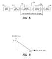
FIG. 8 graphically illustrates an aspect of the process of FIGS. 7A and 7B.
FIG. 9 is a functional block diagram that illustrates aspects of noise reduction filtering performed according to still other embodiments in the apparatus of FIG. 2.
FIGS. 10A and 10B together form a flow chart that illustrates a process that may be performed in connection with the functional arrangement of FIG. 9.
DETAILED DESCRIPTION
FIG. 1 is a block diagram of an apparatus 100 which generates a video bitstream from captured images in accordance with some embodiments.
The apparatus 100 includes a video signal capture device 102 such as a digital video camera. The apparatus 100 further includes a pre-processing block 104 which is coupled to the video signal capture device 102. The pre-processing block 104 performs one or more kinds of pre-processing on the captured video signal provided by the video signal capture device 102. For example, the pre-processing block 104 may perform one or more different kinds of noise reduction processing as in one of the embodiments described below.
The apparatus 100 also includes a compression encoding block 106 which is coupled to the pre-processing block 104. The compression encoding block 106 may apply compression encoding in accordance with conventional practices to the pre-processed video signal provided by the pre-processing block 104.
In addition, the apparatus 100 may include a transmitter 108 coupled to the compression encoding block 106 to transmit the compression encoded video signal in the form of a video signal bitstream over a communication channel which is not separately shown.
Details of embodiments of the pre-processing block 104 will be discussed below.
FIG. 2 is a block diagram of an apparatus 200 which generates a video display from a video bitstream in accordance with some embodiments.
The apparatus 200 includes a source 202 of a video signal bitstream. For example, the video signal source 202 may receive a video signal via a communication channel (which is not separately shown) or may reproduce a video signal from a storage medium such as a DVD or a hard disk drive. For example, the video signal source may include a video tuner, a satellite earth station, or a DVD player. It will be assumed that the video signal bitstream represents a video signal that has been compression encoded, e.g., in accordance with one of the MPEG compression standards. The video signal source 202 may operate in accordance with conventional practices.
The apparatus 200 also includes a video decoder 204 which is coupled to the video signal source to de-compress the video signal bitstream supplied by the video signal source 202. The video decoder 204 may operate in accordance with conventional principles, and may tend to produce artifacts in the output video image, subject to amelioration via embodiments to be described below.
The apparatus 200 further includes a post-processing block 206 which is coupled to the video decoder 204. The post-processing block 206 performs one or more kinds of post processing on the decompressed video signal output from the video decoder 204. For example, the post-processing block 206 may perform one or more different kinds of noise reduction processing as in one or more of the embodiments described below.
In addition, the apparatus 200 includes a display device 208, such as a conventional television set or a computer display monitor. The display device 208 displays the video signal that is output from the post-processing block 206.
FIG. 3 is a functional block diagram that illustrates aspects of a noise reduction process performed in the pre-processing block 104 or in the post-processing block 206 in accordance with some embodiments.
Block 302 represents the pre-processing block 104 or the post-processing block 206 (or a noise reduction sub-block) receiving an input video signal (e.g., directly or indirectly from the video capturing device 102, or directly or indirectly from the video decoder 204) that is to be subjected to noise reduction processing. Block 304 represents circuitry (specially designed or programmed) provided in accordance with some embodiments to apply a filtering process that may be referred to as a “content adaptive substitute filtering” process. As will be described below in more detail, prospective pixel values to be used for filtering are (as indicated by block 306) compared with target pixel values and are replaced in some cases to support improved low-pass filtering (indicated by block 308). Output of the resulting low-pass filtered video signal is indicated at block 310.
FIG. 4 is a flow chart that illustrates an embodiment of a content adaptive substitute filtering process that may be performed in block 304 (FIG. 3). Referring now to FIG. 4, block 402 represents block 304 receiving the input video signal (e.g., after video capture or after de-compression of a previously compression-encoded video signal). Block 404 represents selection of a target pixel x from the input video signal. The target pixel x is the pixel for which a filtered output value is now to be calculated. In a particular example of content adaptive substitute filtering, the filter output value for each target pixel is determined on the basis of pixel values in a filter support neighborhood area that is a three-pixel-by-three-pixel square centered on the target pixel x. This area may be referred to as NH(x) or, since the total area corresponds to 9 pixels, as NH9(x). (In some embodiments, a filter support area other than three-pixels-by-three-pixels may be used. For example, filter support areas of four-pixels-by-four-pixels, five-pixels-by-five-pixels, six-pixels-by-six-pixels or seven-pixels-by-seven-pixels may be used in alternative embodiments.)
At 406 in FIG. 4, the value of one of the neighboring pixels y in NH9(x) is compared with the value of pixel x. At 408 it is determined whether the absolute value of the difference between the two pixel values is at least as great as a threshold amount TH(x). (In the particular embodiment now being discussed, TH(x) may be a constant that is used in connection with all target pixels, but in other embodiments, as described below, TH(x) may vary from target pixel to target pixel. In some embodiments, the constant used for TH(x) may be programmable by a user or designer of the apparatus 100 or 200.)
If at 408 it is determined that the absolute value of the difference between the two pixel values is at least as great as TH(x), then, at 410, the value of neighboring pixel y is replaced with the value of the target pixel x for the purposes of applying a filtering function to calculate an output filtered pixel value for the target pixel. If at 408 it is determined that the absolute value of the difference between the two pixel values is less than TH(x), then the value of the neighboring pixel is not replaced. Following 408 in the latter case, or following 410, as the case may be, is a decision block 412, at which it is determined whether there remain any neighboring pixels in NH9(x), which have not been compared with the target pixel. If such is the case, then the process of FIG. 4 loops back to 406 for consideration of another neighboring pixel in NH9(x). If such is not the case, the process proceeds to apply a low-pass filter characteristic to generate a filtered output value for the target pixel, as indicated at 414 and as will be discussed further below.
FIG. 5 schematically illustrates an example of how the loop 406-412 may operate in connection with a particular target pixel x. The original condition of NH(x) is indicated at 502, with the target pixel x being represented by the solid black pixel at the center of the array shown at 502. The hollow circles in the array 502 represent neighboring pixels for which the values differ from the value of pixel x (if at all) by less than TH(x). The shaded circles in the array 502 represent neighboring pixels for which the values differ from the value of pixel x by at least TH(x). As indicated schematically at 504, the values of the latter neighboring pixels are replaced by the value of the target pixel x to form a substitute filter support array SNH(x). The set of pixel values represented by SNH(x) includes the value of the target pixel and “current values” of the neighboring pixels, where the current value of a neighboring pixel is the original value of the pixel if the value has not undergone replacement and is the value of the target pixel if replacement has occurred. By operation of this compare and replace process, outlier pixel values are removed from the filter support area so that more satisfactory filter results may be obtained. At the same time, the outlier values are each replaced with the target pixel value, so that the number of input values for the filtering function is the same for each target pixel, thereby reducing complexity of hardware implementation. This is in contrast to the known “sigma filter”, in which outlier values are simply discarded, leading to varying numbers of input values and complex implementation.
Referring again to 412 in FIG. 4, in some embodiments the filter function to be applied to generate the output filtered value for the target pixel x may be defined by the following weight matrix:
[ 1 2 1 2 4 2 1 2 1 ]
To reduce the complexity of the calculations, this two-dimensional matrix may be decomposed into two one dimensional matrices:
[ 1 2 1 ] * [ 1 2 1 ]
(Filter characteristics other than that indicated above may be used in other embodiments. For example, filter characteristics suitable for other sizes of filter support may be used.)
In some embodiments, the output filtered value for the target pixel x may be calculated as follows:
( 1 / 16 ) * ( ( y NH9 ( x ) w ( y ) * { y } ) + 8 ) ,
where w(y) is the value of the weighting matrix at the position of the pixel yεNH9(x), and {y} is the value of that pixel. It will be noted that 16 is the summation over the weighting matrix and 8 is one-half of that summation, the latter term being applied for purposes of rounding.
In other embodiments, other filter functions may be applied. Also, in other embodiments, other sizes and/or shapes of filter support areas may be employed rather than the above-described three-pixel-by-three-pixel filter support area.
Once the filter function has been applied to SNH(x) and the resulting output filtered value for the target pixel has been calculated, the output filtered value may be stored, as indicated at 416 in FIG. 4. It is next determined, at decision block 418, whether output filtered values have been obtained for all of the target pixels in the image that is being processed. If not, the process of FIG. 4 loops back to 404. Otherwise the process is complete. It will be appreciated that the content adaptive substitute filter process illustrated in FIG. 4 may be applied to each image represented by the input video signal.
The content adaptive substitute filtering arrangement of FIGS. 3-5 may provide improved noise reduction filtering with a low degree of implementation complexity.
FIG. 6 is a functional block diagram that illustrates aspects of a noise reduction process performed in the pre-processing block 104 or in the post-processing block 206 in accordance with some other embodiments. In these other embodiments, operation of the content adaptive substitute filtering may be modified to incorporate adaptation of the substitution threshold amount TH(x) by taking into consideration the presence of edge conditions at the target pixel x.
Referring to FIG. 6, the functional blocks that were discussed above in connection with FIG. 3 are also present in FIG. 6, except that blocks 304′ and 306′ in FIG. 6 reflect capability to modify in the value of TH(x) from target pixel to target pixel. In addition, the arrangement of FIG. 6 includes a functional block 602 which performs edge detection processing at each target pixel.
FIGS. 7A and 7B together form a flow chart that illustrates an embodiment of an edge-sensitive content adaptive substitute filtering process that may be performed by blocks 602 and 304′ of FIG. 6. The process of FIGS. 7A and 7B may begin with the same blocks 402 and 404 discussed above in connection with FIG. 4. In addition, the process of FIGS. 7A and 7B includes a block 702 at which an edge metric EM(x) is calculated with respect to the target pixel x. In some embodiments, the so-called Sobel edge detector may be employed, using the following matrices:
E_h = [ - 1 - 2 - 1 0 0 0 1 2 1 ] and E_v = [ - 1 0 1 - 2 0 2 - 1 0 1 ]
The edge metric value may be calculated as follows as the convolution of the edge detection weighting matrices with the 3×3 neighborhood NH9(x) of the target pixel:
EM(x)=|NH9(x)*E h|+|NH9(x)*E v|
At 704 an edge-related substitution threshold ETH(x) is calculated to be used (in place of the above described threshold TH(x)) in a content adaptive substitute filtering process to be applied to the target pixel. ETH(x) may be a function of the calculated edge metric EM(x) for the target pixel; i.e.:
ETH(x)=f(EM(x))=C*EM(x)+Th 0,
where C and Th_0 may be predetermined (and/or programmable) constants, and ETH(x) is constrained to be non-negative, Th_0 is greater than zero and C is less than zero. FIG. 8 graphically illustrates ETH(x). It will be appreciated that with increasing edge strength at the target pixel, the substitution threshold is reduced, so that the amount of filtering at the target pixel may be reduced. If the edge metric EM(x) reaches or exceeds a saturation point EM_s, the substitution threshold is reduced to zero and no filtering occurs at the target pixel. Thus strong edges are preserved unfiltered and blurring due to noise reduction filtering may be reduced.
Other edge detection processes besides the above-described Sobel edge detector may be employed in place of the Sobel edge detector in some embodiments. For example, the Canny edge detector may be used.
The balance of the process blocks in the process of FIGS. 7A and 7B may be the same as the blocks described above in connection with FIG. 4. In regard to the process of FIGS. 7A and 7B and other processes described herein, the illustrations and descriptions of the processes are not intended to imply a fixed order of process stages. Rather, the process stages may be performed in any order that is practicable. For example, instead of calculating the edge metric and edge-sensitive substitution threshold for each target pixel as it is selected, one or both of edge detection and threshold calculation may be performed for all target pixels in an image before substituting any neighboring pixel values and performing filtering with respect to any target pixel in the image.
FIG. 9 is a functional block diagram that illustrates aspects of a noise reduction process performed in the post-processing block 206 in accordance with still other embodiments. In the embodiments now to be described in connection with FIGS. 9, 10A and 10B, determination of the substitution threshold reflects both edge conditions at the target pixel and a degree of quantization previously applied during compression encoding to a now-decoded (decompressed) video signal that is to be filtered for noise reduction purposes.
FIG. 9 shows blocks 202 and 204 discussed above in connection with FIG. 2, blocks 302 and 310 discussed in connection with FIG. 3 and block 602 discussed in connection with FIG. 6. In addition, the content adaptive substitute block (now labeled 304″), and in particular its constituent compare and replace block (now labeled 306″) are also present, with the compare and replace block 306″ having been modified to receive from the video decoder block 204 a signal that indicates a degree of quantization employed in the compression-encoding of the video signal decoded by block 204. The compare and replace block 306″ generates substitution threshold values based both on edge conditions detected by block 602 and on the signal from the video decoder 204 to indicate the degree of quantization. FIGS. 10A and 10B together form a flow chart that illustrates an embodiment of a decoder-assisted edge-sensitive adaptive substitute filtering process that may be performed by blocks 602 and 304″ of FIG. 9. The process of FIGS. 10A and 10B may begin with the same block 402 as discussed in connection with FIG. 4. At 1002 in FIG. 10A, the compare and replace block 306″ receives from the video decoder 204 a quantization parameter signal QP(x) which increases in proportion to the degree of quantization (coarseness of quantization) that was applied during compression encoding of the video signal decoded by the video decoder 204.
The process of FIGS. 10A and 10B further includes block 404 discussed above in connection with FIG. 4, and block 702 discussed above in connection with FIG. 7A. At 1004 a quantization-adaptive edge-related substitution threshold ETH(x) is calculated to be used in a content adaptive substitute filtering process to be applied to the target pixel. In some embodiments, ETH(x) may be calculated according to the following formula:
ETH(x)=C*EM(x)+K*QP(x),
where K is a pre-determined (and/or programmable) constant. Both K and QP(x) are greater than zero in this example; C and EM(x) are as described in connection with 702 and 704 of FIG. 7A. With this arrangement, the degree of filtering that may be performed by block 304″ may increase with the degree of quantization applied to the video signal during compression encoding. This may be desirable, since an increased amount of coding noise may be present where more quantization was applied.
The balance of the process blocks in the process of FIGS. 10A and 10B may be the same as the blocks described above in connection with FIG. 4.
In some embodiments, edge detection may be omitted or may not be present and/or C may be set to zero, so that the substitution threshold is quantization-adaptive but not edge-related.
The edge detection block and/or the content adaptive substitute filtering block, or other blocks herein, may be implemented as application-specific logic circuitry or by one or more programmable processors controlled by software instructions stored in a memory or memories coupled to the processor or processors.
The several embodiments described herein are solely for the purpose of illustration. The various features described herein need not all be used together, and any one or more of those features may be incorporated in a single embodiment. Therefore, persons skilled in the art will recognize from this description that other embodiments may be practiced with various modifications and alterations.

Claims (20)

1. A method of operating a noise reduction circuit, the method comprising:
calculating, in the noise reduction circuit, an edge metric for a target pixel;
comparing, in said noise reduction circuit, a value of said target pixel with a respective value of each of a plurality of pixels located in an area that includes the target pixel;
for each pixel of said plurality of pixels that has a value different by at least a threshold amount from the value of the target pixel, replacing in the noise reduction circuit the value of said each pixel with the value of the target pixel; and
applying a filter function in the noise reduction circuit to a set of pixel values, said set of pixel values including the value of the target pixel and current values, after said replacing, of said plurality of pixels;
wherein said threshold amount is a function of said edge metric for said target pixel.
2. The method of claim 1, wherein said target pixel and said plurality of pixels are part of an image that has been decompressed from a compressed image signal, said compressed image signal having been compressed by a process that includes quantization with a degree of quantization, said threshold amount being based in part on said degree of quantization.
3. The method of claim 1, wherein said target pixel and said plurality of pixels are part of an image that has been decompressed from a compressed image signal, said compressed image signal having been compressed by a process that includes quantization with a degree of quantization, said threshold amount being based at least in part on said degree of quantization.
4. A system comprising:
a source of a video signal;
a noise reduction circuit coupled to said source of a video signal; and
a compression encoding circuit coupled to said noise reduction circuit;
said noise reduction circuit operative to:
subtract a value of a target pixel from a respective value of each of a plurality of pixels located in an area that includes the target pixel;
for each pixel of said plurality of pixels that has a value different by at least a threshold amount from the value of the target pixel, replace the value of said each pixel with the value of the target pixel; and
apply a filter function to a set of pixel values, said set of pixel values including the value of the target pixel and current values, after said replacing, of said plurality of pixels, said filter function producing a filtered video signal that is output from said noise reduction circuit;
wherein said compression encoding circuit receives said filtered video signal from said noise reduction circuit and compression-encodes said filtered video signal.
5. The system of claim 4, wherein said noise reduction circuit is further operative to:
store an output value of said filter function as a filtered value of the target pixel.
6. The system of claim 4, wherein the area is a three-pixel-by-three-pixel square.
7. The system of claim 6, wherein the filter function is defined by a weight matrix as follows:
[ 1 2 1 2 4 2 1 2 1 ] .
8. The system of claim 4, wherein said noise reduction circuit is further operative to:
before said replacing, calculate an edge metric for said target pixel;
and wherein said threshold amount is a function of said edge metric for said target pixel.
9. A system comprising:
a video decoder to decompress a compression-encoded video signal; and
a noise reduction circuit coupled to said video decoder and operative to:
calculate an edge metric for a target pixel;
compare a value of said target pixel with a respective value of each of a plurality of pixels located in an area that includes the target pixel; and
for each pixel of said plurality of pixels that has a value different by at least a threshold amount from the value of the target pixel, replace the value of said each pixel with the value of the target pixel;
wherein said threshold amount is a function of said edge metric for said target pixel.
10. The system of claim 9, wherein:
said video decoder is operative to provide to said noise reduction circuit a signal indicative of a degree of quantization applied to said compression-encoded video signal during compression-encoding thereof; and
said threshold amount is determined by said noise reduction circuit based in part on said signal indicative of said degree of quantization.
11. The system of claim 9, wherein:
said video decoder is operative to provide to said noise reduction circuit a signal indicative of a degree of quantization applied to said compression-encoded video signal during compression-encoding thereof; and
said threshold amount is determined by said noise reduction circuit based at least in part on said signal indicative of said degree of quantization.
12. A method of operating a noise reduction circuit, the method comprising:
calculating, in the noise reduction circuit, an edge metric for a target pixel;
subtracting, in the noise reduction circuit, a value of said target pixel from a respective value of each of a plurality of pixels located in an area that includes the target pixel;
for each pixel of said plurality of pixels that has a value different by at least a threshold amount from the value of the target pixel, replacing in the noise reduction circuit the value of said each pixel with the value of the target pixel; and
filtering a set of pixel values in the noise reduction circuit, said set of pixel values including the value of the target pixel and current values, after said replacing, of said plurality of pixels;
wherein said threshold amount is a function of said edge metric for said target pixel.
13. The method of claim 12, further comprising:
storing a result of said filtering as a filtered value of the target pixel.
14. The method of claim 12, wherein the area is a three-pixel-by-three-pixel square.
15. The method of claim 1, further comprising:
storing an output value of said filter function as a filtered value of the target pixel.
16. The method of claim 1, wherein the area is a three-pixel-by-three-pixel square.
17. The method of claim 16, wherein the filter function is defined by a weight matrix as follows:
[ 1 2 1 2 4 2 1 2 1 ] .
18. The system of claim 9, wherein said noise reduction circuit is further operative to:
store an output value of a filter function as a filtered value of the target pixel.
19. The system of claim 9, wherein the area is a three-pixel-by-three-pixel square.
20. The system of claim 19, wherein the filter function is defined by a weight matrix as follows:
[ 1 2 1 2 4 2 1 2 1 ] .
US11/230,148 2005-09-19 2005-09-19 Content adaptive noise reduction filtering for image signals Expired - Fee Related US7804896B2 (en)

Priority Applications (5)

Application Number Priority Date Filing Date Title
US11/230,148 US7804896B2 (en) 2005-09-19 2005-09-19 Content adaptive noise reduction filtering for image signals
PCT/US2006/029528 WO2007040765A1 (en) 2005-09-19 2006-07-27 Content adaptive noise reduction filtering for image signals
KR1020087006603A KR101031438B1 (en) 2005-09-19 2006-07-27 Content adaptive noise reduction filtering for image signals
CNB2006101399052A CN100512376C (en) 2005-09-19 2006-09-18 Content adaptive noise reduction filtering for image signals
US12/862,175 US8218082B2 (en) 2005-09-19 2010-08-24 Content adaptive noise reduction filtering for image signals

Applications Claiming Priority (1)

Application Number Priority Date Filing Date Title
US11/230,148 US7804896B2 (en) 2005-09-19 2005-09-19 Content adaptive noise reduction filtering for image signals

Related Child Applications (1)

Application Number Title Priority Date Filing Date
US12/862,175 Continuation US8218082B2 (en) 2005-09-19 2010-08-24 Content adaptive noise reduction filtering for image signals

Publications (2)

Publication Number Publication Date
US20070064792A1 US20070064792A1 (en) 2007-03-22
US7804896B2 true US7804896B2 (en) 2010-09-28

Family

ID=37114432

Family Applications (2)

Application Number Title Priority Date Filing Date
US11/230,148 Expired - Fee Related US7804896B2 (en) 2005-09-19 2005-09-19 Content adaptive noise reduction filtering for image signals
US12/862,175 Expired - Fee Related US8218082B2 (en) 2005-09-19 2010-08-24 Content adaptive noise reduction filtering for image signals

Family Applications After (1)

Application Number Title Priority Date Filing Date
US12/862,175 Expired - Fee Related US8218082B2 (en) 2005-09-19 2010-08-24 Content adaptive noise reduction filtering for image signals

Country Status (4)

Country Link
US (2) US7804896B2 (en)
KR (1) KR101031438B1 (en)
CN (1) CN100512376C (en)
WO (1) WO2007040765A1 (en)

Cited By (2)

* Cited by examiner, † Cited by third party
Publication number Priority date Publication date Assignee Title
US20100272191A1 (en) * 2008-01-14 2010-10-28 Camilo Chang Dorea Methods and apparatus for de-artifact filtering using multi-lattice sparsity-based filtering
US9183617B2 (en) 2009-10-30 2015-11-10 Agency For Science, Technology And Research Methods, devices, and computer readable mediums for processing a digital picture

Families Citing this family (14)

* Cited by examiner, † Cited by third party
Publication number Priority date Publication date Assignee Title
US8447130B2 (en) * 2007-12-31 2013-05-21 Intel Corporation History-based spatio-temporal noise reduction
US8149093B2 (en) * 2008-06-06 2012-04-03 Lyngsoe Systems System and method for wireless communications
CN101742288B (en) * 2008-11-11 2013-03-27 北京中星微电子有限公司 Video noise reduction encoding method and video noise reduction encoding device
EP2422522A1 (en) 2009-04-20 2012-02-29 Dolby Laboratories Licensing Corporation Directed interpolation and data post-processing
US8687911B2 (en) * 2009-06-24 2014-04-01 Nokia Corporation Adaptive method for processing digital images, and an image processing device
CN102006430B (en) * 2009-09-02 2013-07-10 英属开曼群岛商恒景科技股份有限公司 Noise removing method applied to image sensor and relevant device
KR101105689B1 (en) * 2010-02-09 2012-01-17 아엠아이테크 주식회사 A modified median noise removal filtering method using cross-typed window
WO2012073866A1 (en) * 2010-11-30 2012-06-07 シャープ株式会社 Signal processing device, signal processing method, signal processing program, and display device
WO2012081609A1 (en) * 2010-12-14 2012-06-21 シャープ株式会社 Image filter device, decoder, encoder, and data structure
US8873821B2 (en) * 2012-03-20 2014-10-28 Paul Reed Smith Guitars Limited Partnership Scoring and adjusting pixels based on neighborhood relationships for revealing data in images
CN105450909B (en) * 2014-06-27 2019-12-24 联想(北京)有限公司 Information processing method and electronic equipment
US9576346B2 (en) * 2015-03-24 2017-02-21 Intel Corporation Non-local means image denoising with an adaptive directional spatial filter
CN106296754B (en) * 2015-05-20 2019-06-18 上海和辉光电有限公司 Show data compression method and display data processing system
US10867374B2 (en) 2017-02-13 2020-12-15 Sensors Unlimited, Inc. Auto-focusing system and method by determining contrast difference between adjacent pixels using sobel filter

Citations (7)

* Cited by examiner, † Cited by third party
Publication number Priority date Publication date Assignee Title
US5786857A (en) * 1993-10-01 1998-07-28 Texas Instruments Incorporated Image processing system
US20030020835A1 (en) 2001-05-04 2003-01-30 Bops, Inc. Methods and apparatus for removing compression artifacts in video sequences
US20040081368A1 (en) 2002-10-25 2004-04-29 Reji Mathew Method and decoder system for reducing quantization effects of a decoded image
US7327785B2 (en) * 2003-07-01 2008-02-05 Tandberg Telecom As Noise reduction method, apparatus, system, and computer program product
US7400679B2 (en) * 2004-04-29 2008-07-15 Mediatek Incorporation Adaptive de-blocking filtering apparatus and method for MPEG video decoder
US7403568B2 (en) * 2003-08-13 2008-07-22 Apple Inc. Pre-processing method and system for data reduction of video sequences and bit rate reduction of compressed video sequences using temporal filtering
US7496141B2 (en) * 2004-04-29 2009-02-24 Mediatek Incorporation Adaptive de-blocking filtering apparatus and method for MPEG video decoder

Patent Citations (7)

* Cited by examiner, † Cited by third party
Publication number Priority date Publication date Assignee Title
US5786857A (en) * 1993-10-01 1998-07-28 Texas Instruments Incorporated Image processing system
US20030020835A1 (en) 2001-05-04 2003-01-30 Bops, Inc. Methods and apparatus for removing compression artifacts in video sequences
US20040081368A1 (en) 2002-10-25 2004-04-29 Reji Mathew Method and decoder system for reducing quantization effects of a decoded image
US7327785B2 (en) * 2003-07-01 2008-02-05 Tandberg Telecom As Noise reduction method, apparatus, system, and computer program product
US7403568B2 (en) * 2003-08-13 2008-07-22 Apple Inc. Pre-processing method and system for data reduction of video sequences and bit rate reduction of compressed video sequences using temporal filtering
US7400679B2 (en) * 2004-04-29 2008-07-15 Mediatek Incorporation Adaptive de-blocking filtering apparatus and method for MPEG video decoder
US7496141B2 (en) * 2004-04-29 2009-02-24 Mediatek Incorporation Adaptive de-blocking filtering apparatus and method for MPEG video decoder

Non-Patent Citations (1)

* Cited by examiner, † Cited by third party
Title
"PCT International Search Report of the International Searching Authority", mailed Nov. 14, 2006, for PCT/US2006/029528, 3pgs.

Cited By (2)

* Cited by examiner, † Cited by third party
Publication number Priority date Publication date Assignee Title
US20100272191A1 (en) * 2008-01-14 2010-10-28 Camilo Chang Dorea Methods and apparatus for de-artifact filtering using multi-lattice sparsity-based filtering
US9183617B2 (en) 2009-10-30 2015-11-10 Agency For Science, Technology And Research Methods, devices, and computer readable mediums for processing a digital picture

Also Published As

Publication number Publication date
US20070064792A1 (en) 2007-03-22
CN100512376C (en) 2009-07-08
KR20080038415A (en) 2008-05-06
KR101031438B1 (en) 2011-04-26
CN1937713A (en) 2007-03-28
US20100315558A1 (en) 2010-12-16
US8218082B2 (en) 2012-07-10
WO2007040765A1 (en) 2007-04-12

Similar Documents

Publication Publication Date Title
US7804896B2 (en) Content adaptive noise reduction filtering for image signals
RU2461977C2 (en) Compression and decompression of images
JP4847890B2 (en) Encoding method converter
US7680355B2 (en) Detection of artifacts resulting from image signal decompression
JP4455487B2 (en) Decoding device, decoding method, and program
US9092855B2 (en) Method and apparatus for reducing noise introduced into a digital image by a video compression encoder
US7076113B2 (en) Apparatus and method for adaptive spatial segmentation-based noise reducing for encoded image signal
EP2207358A1 (en) Video decoding method and video encoding method
US20080101469A1 (en) Method and apparatus for adaptive noise filtering of pixel data
JP2005166021A (en) Method for classifying pixel in image
JP4762352B1 (en) Image processing apparatus and image processing method
US20070285729A1 (en) Image processing apparatus and image processing method
US10142604B2 (en) Imaging apparatus and control method thereof
US8442338B2 (en) Visually optimized quantization
US20120133836A1 (en) Frame level quantization estimation
JP3081658B2 (en) Image signal encoding device and image signal decoding device
Matsuo et al. Video coding of 8K UHDTV by HEVC/H. 265 with spatio-gradational reduction and its restoration
US10951891B2 (en) Coding apparatus capable of recording raw image, control method therefor, and storage medium storing control program therefor
JP5413122B2 (en) Image processing method and image processing apparatus
Aqqa et al. CAR-CNN: A Deep Residual Convolutional Neural Network for Compression Artifact Removal in Video Surveillance Systems.
GB2468304A (en) Video image processing method that smooths the jagged diagonal edges created by epsilon filtering
US20070274397A1 (en) Algorithm for Reducing Artifacts in Decoded Video
Goto et al. Blocky noise reduction for JPEG images using total variation minimization
Engelke et al. Quality Assessment of an Adaptive Filter for Artifact Reduction in Mobile Video Sequences
JP2005286710A (en) Image processing apparatus and image processing method

Legal Events

Date Code Title Description
AS Assignment

Owner name: INTEL CORPORATION, CALIFORNIA

Free format text: ASSIGNMENT OF ASSIGNORS INTEREST;ASSIGNORS:CHIU, YI-JEN;KIPPINCOTT, LOUIS;REEL/FRAME:017030/0255

Effective date: 20050916

STCF Information on status: patent grant

Free format text: PATENTED CASE

FPAY Fee payment

Year of fee payment: 4

MAFP Maintenance fee payment

Free format text: PAYMENT OF MAINTENANCE FEE, 8TH YEAR, LARGE ENTITY (ORIGINAL EVENT CODE: M1552)

Year of fee payment: 8

FEPP Fee payment procedure

Free format text: MAINTENANCE FEE REMINDER MAILED (ORIGINAL EVENT CODE: REM.); ENTITY STATUS OF PATENT OWNER: LARGE ENTITY

LAPS Lapse for failure to pay maintenance fees

Free format text: PATENT EXPIRED FOR FAILURE TO PAY MAINTENANCE FEES (ORIGINAL EVENT CODE: EXP.); ENTITY STATUS OF PATENT OWNER: LARGE ENTITY

STCH Information on status: patent discontinuation

Free format text: PATENT EXPIRED DUE TO NONPAYMENT OF MAINTENANCE FEES UNDER 37 CFR 1.362

FP Lapsed due to failure to pay maintenance fee

Effective date: 20220928