US7808525B2 - Transparent camera calibration tool for camera calibration and calibration method thereof - Google Patents
Transparent camera calibration tool for camera calibration and calibration method thereof Download PDFInfo
- Publication number
- US7808525B2 US7808525B2 US11/052,756 US5275605A US7808525B2 US 7808525 B2 US7808525 B2 US 7808525B2 US 5275605 A US5275605 A US 5275605A US 7808525 B2 US7808525 B2 US 7808525B2
- Authority
- US
- United States
- Prior art keywords
- camera
- transparent
- calibration tool
- image
- camera calibration
- Prior art date
- Legal status (The legal status is an assumption and is not a legal conclusion. Google has not performed a legal analysis and makes no representation as to the accuracy of the status listed.)
- Expired - Fee Related, expires
Links
Images


Classifications
-
- G—PHYSICS
- G06—COMPUTING; CALCULATING OR COUNTING
- G06T—IMAGE DATA PROCESSING OR GENERATION, IN GENERAL
- G06T7/00—Image analysis
- G06T7/80—Analysis of captured images to determine intrinsic or extrinsic camera parameters, i.e. camera calibration
-
- G—PHYSICS
- G01—MEASURING; TESTING
- G01B—MEASURING LENGTH, THICKNESS OR SIMILAR LINEAR DIMENSIONS; MEASURING ANGLES; MEASURING AREAS; MEASURING IRREGULARITIES OF SURFACES OR CONTOURS
- G01B11/00—Measuring arrangements characterised by the use of optical techniques
- G01B11/002—Measuring arrangements characterised by the use of optical techniques for measuring two or more coordinates
-
- G—PHYSICS
- G01—MEASURING; TESTING
- G01B—MEASURING LENGTH, THICKNESS OR SIMILAR LINEAR DIMENSIONS; MEASURING ANGLES; MEASURING AREAS; MEASURING IRREGULARITIES OF SURFACES OR CONTOURS
- G01B11/00—Measuring arrangements characterised by the use of optical techniques
-
- G—PHYSICS
- G01—MEASURING; TESTING
- G01B—MEASURING LENGTH, THICKNESS OR SIMILAR LINEAR DIMENSIONS; MEASURING ANGLES; MEASURING AREAS; MEASURING IRREGULARITIES OF SURFACES OR CONTOURS
- G01B21/00—Measuring arrangements or details thereof, where the measuring technique is not covered by the other groups of this subclass, unspecified or not relevant
- G01B21/02—Measuring arrangements or details thereof, where the measuring technique is not covered by the other groups of this subclass, unspecified or not relevant for measuring length, width, or thickness
- G01B21/04—Measuring arrangements or details thereof, where the measuring technique is not covered by the other groups of this subclass, unspecified or not relevant for measuring length, width, or thickness by measuring coordinates of points
- G01B21/042—Calibration or calibration artifacts
-
- G—PHYSICS
- G01—MEASURING; TESTING
- G01C—MEASURING DISTANCES, LEVELS OR BEARINGS; SURVEYING; NAVIGATION; GYROSCOPIC INSTRUMENTS; PHOTOGRAMMETRY OR VIDEOGRAMMETRY
- G01C11/00—Photogrammetry or videogrammetry, e.g. stereogrammetry; Photographic surveying
- G01C11/02—Picture taking arrangements specially adapted for photogrammetry or photographic surveying, e.g. controlling overlapping of pictures
-
- H—ELECTRICITY
- H04—ELECTRIC COMMUNICATION TECHNIQUE
- H04N—PICTORIAL COMMUNICATION, e.g. TELEVISION
- H04N13/00—Stereoscopic video systems; Multi-view video systems; Details thereof
- H04N13/20—Image signal generators
- H04N13/204—Image signal generators using stereoscopic image cameras
- H04N13/239—Image signal generators using stereoscopic image cameras using two 2D image sensors having a relative position equal to or related to the interocular distance
-
- H—ELECTRICITY
- H04—ELECTRIC COMMUNICATION TECHNIQUE
- H04N—PICTORIAL COMMUNICATION, e.g. TELEVISION
- H04N13/00—Stereoscopic video systems; Multi-view video systems; Details thereof
- H04N13/20—Image signal generators
- H04N13/204—Image signal generators using stereoscopic image cameras
- H04N13/246—Calibration of cameras
Definitions
- the present invention relates to a transparent camera calibration tool that is employed in camera calibration of computer vision for estimating parameters of six degrees of freedom (extrinsic parameters) for the position and orientation of a camera and parameters (intrinsic parameters) such as the image center position and lens distortion coefficients, which are camera-specific qualities, and to a geometrical calibration method that employs the transparent camera calibration tool.
- FIG. 20 schematically shows a camera calibration method that uses a conventional calibration tool.
- a calibration tool is disposed close to the object and imaged by means of the camera as a preprocessing to capturing image as shown above on the right, whereupon an image of the calibration tool as shown on the center right is obtained and analyzed and the extrinsic and intrinsic parameters of the camera are calculated and stored.
- a procedure is adopted in which the calibration tool is withdrawn a certain time afterward, the object is captured as illustrated above on the left to obtain an observed image of the object as shown on the center left, whereupon a three-dimensional analysis of the observed image is carried out on the basis of the previous camera extrinsic and intrinsic parameters. Because an analysis of the observed image is performed on the basis of the camera extrinsic and intrinsic parameters obtained from the calibration tool image in this manner, the position and orientation of the camera and the focal length thereof, and so forth, cannot be changed following calibration.
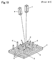
- a perforated board c that is rendered by forming a multiplicity of holes b in the upper side of a plate a as shown in FIG. 19 is provided and calibration poles d of rod material are randomly fitted in optional positions of the multiplicity of holes b in the perforated board c.
- the upper side of plate a is coated black, the upper side of perforated board c is coated gray, and the tops of the calibration poles d are coated white. Further, the lengths of the calibration poles d are set at random.
- Two cameras (a left camera and right camera) e and f are arranged on top of a calibration table in a cross-eye view so that the optical axes of the left camera e and right camera f are roughly joined at a certain point on the calibration table.
- An image of the upper side of the calibration table is taken by left camera e and right camera f.
- the images taken by the left camera e and right camera f are inputted to a coordinate circuit and coordinates are established by the coordinate circuit on the basis of the shading of the images.
- the information of the coordinate circuit is then inputted to a three-dimensional position processing circuit and calibration parameters estimated by a calibration parameter processing circuit are inputted to the three-dimensional position processing circuit.
- the three-dimensional position processing circuit determines a three-dimensional position of a projected point based on the information of the coordinate circuit and calibration parameters. This method is favorable in the case of image pickup of a stationary object but requires a device for moving the camera accurately in order to track a moving image of a person or the like by means of a camera. There is also the problem that, because the calibration tool is installed and withdrawn, same is not suited to an outdoor application or the like.
- the position of the target is detected from this calibration data (CDB) and from the imaging data (CM) for the target in position B of the camera.
- This technique involves establishing a correlation between the coordinates of the target and the coordinates of the camera also when the camera is moved once the calibration has been performed.
- the accuracy of this correlation is linked solely with the degree of accuracy of the movement amount data (CM) for the position and orientation of the camera. Therefore, a highly accurate drive mechanism must be provided. This also entails the fundamental defect that errors accumulate with each successive movement.
- a problem that the present invention is intended to solve is to provide a camera calibration method not requiring the work involved in installing and withdrawing a calibration tool as a preliminary process and which, even when the position and orientation of the camera and the focal length thereof are changed, allows capturing image to be performed by accurately calibrating the camera parameters in accordance with the changes in the position and orientation of the camera and the focal length thereof.
- the calibration tool of the present invention is a transparent camera calibration tool in which a plurality of indicator points is spatially distributed and fixed.
- the indicator points are formed as a group of intersecting points of thin wires rendered by extending a plurality of parallel thin wire groups to a frame in different directions.
- the indicator groups are arranged in at least two sets in a non-coplanar relationship.
- the indicator groups are embodied by distributing distinguishable minute particles in a transparent raw material or by marks or the like in the surface of the raw material.
- the indicator points may be embodied by means of a combination of a transparent plate on which a fluorescent material is arranged and a light source that irradiates an excitation beam.
- a composite-type calibration tool in which a transparent calibration tool comprising a combination of a transparent plate on which fluorescent material is arranged and a light source that irradiates an excitation beam and another such transparent calibration tool are integrated in a state in which relative positions are fixed is proposed.
- the camera calibration method of the present invention comprises the steps of installing a transparent camera calibration tool in which a plurality of indicator points is spatially distributed and fixed in a position close to the front of the camera in a stationary state in a world coordinate system and, as a preprocessing to imaging an object, imaging the plurality of indicator points by setting the lens focus at close range and estimating the extrinsic and intrinsic parameters of the camera from the corresponding image.
- the camera calibration method of the present invention establishes a plurality of indicator points as marks that are distinguishable by means of a specified color filter and estimates extrinsic and intrinsic parameters of a camera from an image that is rendered by overlaying an observed image and the indicator points.
- the camera further comprises a switching filter that is able to transmit or cut a specified color of the marks, wherein the plurality of indicator points is imaged and the extrinsic and intrinsic parameters of the camera are estimated from the image.
- Proposed calibration methods in cases where focus adjustment is required in calibration that employs the transparent camera calibration tool of the present invention include an embodiment in which the observed image and image for calibration are obtained by adjusting the focus of one camera, an embodiment in which the observed image is captured by one of the two cameras, whose positional relationship is already known, while the image for calibration is captured by the other camera, and an embodiment in which one multi-focus camera the focus of which is adjusted to a remote object and to a transparent camera calibration tool in which a plurality of indicator points in a close position is spatially distributed and fixed is used and the position and orientation of the camera are analyzed by obtaining the observed image by means of one camera and the image for calibration by means of the other camera.
- a multi-focus camera that has a zoom function is used and the focal length and so forth is analyzed from the image for calibration according to the change in the zoom is also represented.
- the camera calibration method proposes an embodiment in which a light beam is irradiated onto a transparent plate and indicators are displayed by means of diffused reflection at the surface of the transparent plate or indicators are displayed by arranging fluorescent material on the transparent plate and making the light beam an excitation beam. Camera parameters are then analyzed from the image for calibration rendered by imaging the indicators.
- the stereo camera calibration method involves disposing a transparent camera calibration tool in front of two cameras arranged in different positions in respective positional relationships that are already known in a world coordinate system and then analyzing the parameters of the two cameras from the indicator image of the transparent camera calibration tool.
- the stereo camera calibration method involves disposing, in a stationary state in a world coordinate system, a composite calibration tool produced by combining a transparent camera calibration tool in which a plurality of spatially distributed and fixed indicator points is formed by means of a transparent plate on the surface of which a fluorescent material is disposed and a light source that irradiates an excitation beam and another transparent camera calibration tool in front of two cameras arranged in different positions and then analyzing the parameters of the two cameras from a captured image of points at which four or more light beams irradiated by one light source intersect the transparent plate and from an indicator image of the other transparent camera calibration tool.
- the camera calibration method of the present invention involves installing a transparent camera calibration tool, in which a plurality of indicator points is spatially distributed and fixed, in a position close to the front of camera in a stationary state in a world coordinate system and capturing an image taken of an object and an image for calibration taken of calibration indicator points to perform camera calibration. Because, when the image for calibration is photographed, appropriate usage of focus and color band is employed, the existence of the calibration tool does not constitute any kind of obstacle to the image and therefore need not be withdrawn. Even when the position or orientation of the camera or the focal length thereof is changed, the image for calibration can be obtained simply each time such a change occurs and the extrinsic and intrinsic parameters of the camera can be calibrated accurately from a newly captured image for calibration. Accordingly, even in the case of a moving object, image measurement can be performed while performing image capture and calibration alternately while allowing the camera to track or enlarge the object.
- a composite calibration tool that integrates a transparent calibration tool, which comprises a combination of a transparent plate on which a fluorescent material is disposed and a light source that irradiates an excitation beam, and another such transparent calibration tool in a state in which relative positions are fixed is used and the points at which four or more light beams irradiated by one light source intersect a plate tool are established as indicators, the relative position and orientation of the two sides of the plate can be detected even when the distance between the stereo cameras is large. Therefore, a stereo vision of a remote object can be implemented sensitively.
- the placement of a transparent plate on which a fluorescent material is disposed in front of a plurality of cameras arranged in different positions the combination and arrangement, for any plate tool, of four or more excitation light beams irradiated by one light source so that the light beams intersect at least one other plate tool, and the analysis of the camera parameters from the captured image of the intersecting points and the indicator image of the other transparent camera calibration tool make it possible to grasp a plurality of camera position/orientation relationships and, therefore, implement highly accurately a multi-view stereo vision of a large space such as a baseball ground, soccer pitch, airport, or the like can be implemented highly accurately.
- the calibration method of the present invention is capable of grasping changes in camera position and orientation resulting from age-related degradation caused by vibration and so forth and may therefore be associated with an increase in reliability. Further, in a conventional calibration method, because the calibration tool is removed following calibration, it is difficult to specify the orientation and position of the origin in a world coordinate system, which is an obstacle to a practical application. However, the technique of the present invention affords the benefit of being able to specify clearly a world coordinate system represented by the transparent camera calibration tool. The technique of the present invention can also easily adapt to the calibration of camera parameters that accompanies changes in the zoom, which has been a burden conventionally, in the case of a camera equipped with a zoom mechanism.
- the calibration tool of the present invention is a transparent camera calibration tool that is rendered by arranging indicator groups in at least two sets in a non-coplanar relationship, the indicator groups being rendered by forming intersecting points of thin wires extended to a frame as a group of intersecting points of thin wires rendered by extending a plurality of parallel thin wire groups in different directions and by spatially distributing and fixing a plurality of indicator points that are embodied by forming distinguishable minute particles in a transparent raw material, and so forth. Therefore, even when the calibration tool is disposed directly in front of the camera, the presence of the calibration tool represents no obstacle whatsoever when the object is imaged, and the position of the indicator points can be distinguished on the image.
- the transparent camera calibration tool in which a plurality of indicator points are embodied by means of a combination of a transparent plate, which is rendered by arranging a distinguishable color filter and fluorescent material in a transparent raw material, and a light source that irradiates an excitation beam, the transparent camera calibration tool is able to operate without being an obstacle at the time of photography of an object even when the calibration tool is placed at close range, which causes focal blur.
- the calibration tool according to the present invention is also easily carried around with a camera and is easy to install, meaning that applications to camera systems in a variety of forms and additional applications for existing camera systems can be expected.
- FIG. 1 shows an example of the transparent camera calibration tool of the present invention in which a group of intersecting points of wires extending to a frame are the indicator points;
- FIG. 2 shows an example of the transparent camera calibration tool of the present invention in which a calibration pattern is added to a transparent material as an indicator;
- FIG. 3 shows an example of the transparent camera calibration tool of the present invention in which a color filter indicator is added to a transparent material
- FIG. 4 illustrates an example of the transparent camera calibration tool of the present invention that is used in a stereo camera system
- FIG. 5 illustrates an example of the transparent camera calibration tool of the present invention in which the intersecting points of two transparent plates and a plurality of light beams serve as indicators;
- FIG. 6 illustrates an analysis method that derives a plane equation that uses four straight lines and the intersecting points thereof
- FIG. 7 illustrates a method of analyzing relative position relationships of each plane from the positions of three or more transparent plates and the intersecting points of a plurality of light beams
- FIG. 8 shows a first embodiment of the transparent camera calibration tool of the present invention
- FIG. 9 illustrates a first embodiment of the calibration method of the present invention that uses the transparent camera calibration tool and one camera;
- FIG. 10 illustrates another embodiment of the calibration method of the present invention that uses the transparent camera calibration tool and two cameras;
- FIG. 11 illustrates yet another embodiment of the calibration method of the present invention that uses the transparent camera calibration tool and one multi-focus camera;
- FIG. 12 illustrates the analysis of camera parameters that vary according to changes in the zoom by means of the calibration method of the present invention that uses the multi-focus camera of FIG. 11 ;
- FIG. 13 is a scene image in which the transparent camera calibration tool and an object are placed in order to perform imaging by means of two cameras that are fixed side by side on a stage with 6 degrees of freedom;
- FIG. 14 is an example of imaging of an image for calibration and an observed image that are captured in the scene of FIG. 13 ;
- FIG. 15 illustrates an embodiment example of a calibration tool that is rendered by adding indicators to a transparent plate by means of a color filter as well as the calibration method thereof;
- FIG. 16 illustrates a comparison between images that are obtained by selecting the RGB signal of the camera in an embodiment example that uses the calibration tool rendered by adding indicators to a transparent plate by means of a color filter;
- FIG. 17 illustrates an embodiment example of a stereo camera calibration tool that is installed in an airport as well as the calibration method thereof;
- FIG. 18 is a PnP problem diagram showing world coordinates and camera coordinates in camera calibration
- FIG. 19 shows an example of a conventional calibration tool
- FIG. 20 illustrates a calibration method that is implemented by using a conventional calibration tool.
- the essence of the problem with conventional camera calibration may be attributed to the calibration tool. If the calibration tool were always able to be projected within an image, the problems would be solved. However, this is not realistic due to the labor involved in installation and the problems of interference with an observed image.
- the basic concept of the present invention is to provide a calibration tool that is able to be projected at any time and without interfering with an observed image and to propose a method of using the calibration tool.
- the present invention attempts to solve this problem by proposing a transparent camera calibration tool.
- the transparent camera calibration tool of this specification signifies a tool that is capable of imaging, by means of the camera, an object that lies opposite the camera even when a calibration tool is interposed between the camera and the object.
- the present invention utilizes the characteristics of a transparent camera calibration tool and is employed installed directly in front of the camera. General cameras are confronted by the problem of focus adjustment. When focusing does not take place, blurring occurs instead of an image of the target being formed in the imaging area.
- the transparent camera calibration tool of the present invention uses the characteristics of the camera and, when focusing is implemented at close range, the transparent camera calibration tool, which is installed directly in front of the camera, is able to take clear shapes.
- the transparent camera calibration tool is advantageous in that same need not be withdrawn each time an observed image is captured and allows an image to be taken without moving the transparent camera calibration tool. Further, even when the position and orientation of the camera is changed, as long as an image rendered by focusing on the transparent camera calibration tool is acquired, a response to the amount of variation between the world coordinate system and the camera coordinate system can be implemented by analyzing the image.
- Japanese Patent Application Laid Open No. H8-43026 discloses a calibration device for which a color system is extended in the form of a lattice and in three dimensions. This is structurally similar to the ‘tool with a constitution in which indicator points are formed as a group of intersecting points of thin wires rendered by extending a plurality of parallel thin wire groups in different directions and the indicator groups are arranged in at least two sets in a non-coplanar relationship’ of the present invention.
- wire groups in optical directions are distinguished according to color, the color-coding requirement differs from the directional change requirement of the present invention.
- the intrinsic parameters can be used when same are calibrated and recorded by means of a conventional method beforehand.
- conversion of the coordinate system and image measurement and analysis by using intrinsic parameters that have been calibrated beforehand and extrinsic parameters that are sequentially measured by means of the present invention are effective.
- the present invention proposes a transparent camera calibration tool that utilizes a bandpass filter and performs simultaneous capture of an observed image and image for calibration through appropriate band usage in order to solve the problem of the withdrawal and installation of the calibration tool.
- a band that allows transmission without attenuation and a shielded band exist because of the bandpass filter.
- the shielded band serves as a calibrated image and the image of the transmission band can be used as the image.
- This method can be applied to a normal color camera by using a color filter constituting a visible-range bandpass filter.
- the color band used as the shielding band is the calibrated image
- the observed image is not in full color.
- computer vision is mostly performed based on an image of a single band, the obstacle is small even when the observed image is not in full color.
- Simultaneous capture of an image for calibration and an observed image is proposed as a method for solving the problem of the withdrawal and installation of the calibration tool.
- appropriate usage of focus and capturing band is employed and respective transparent camera calibration tools and usage methods thereof are proposed. Further, these methods can also be used effectively in combination depending on the conditions.
- the present invention is based on calibration of camera parameters for the three-dimensional positions of spaces in a calibration pattern that is projected in the image for calibration and two-dimensional positions on the surface of the image.
- a straightforward explanation of an algorithm for calculating camera parameters is provided here.
- a total of eleven parameters are found by means of this calibration, namely, six extrinsic parameters that express the position and orientation of the camera and five intrinsic parameters that express qualities specific to the camera.
- the six extrinsic parameters that express the position and orientation of the camera are expressed by means of a relative relationship between the world coordinates and camera coordinates and can be expressed by means of a rotation matrix and translation vectors.
- the problem of determining six extrinsic parameters from an image that is rendered by using a camera to image a plurality of n points, for which information on the position in world coordinates is known, is known as the PnP (perspective n-point) problem and is well-known. This aspect is shown in FIG. 18 .
- the calibration step has two stages, which include a step of estimating a projection matrix P that establishes a projection between three-dimensional points [X, Y,Z,1] T based on world coordinates and a two-dimensional source image [u,v,1] T based on camera coordinates for these points and a step of determining an intrinsic parameters A and extrinsic parameters R and t from this projection matrix.
- a projection equation for a perspective projection is expressed by means of the following formulae:
- This projection matrix P is a 3 ⁇ 4 matrix with twelve elements.
- Two linear equations (2) relating to element P can be established from one item of three-dimensional point information and two-dimensional image information thereof.
- P 1 T M i ⁇ u i P 3 T M i +p 14 ⁇ u i p 34 0
- P 2 T M i ⁇ v i P 3 T M i +p 24 ⁇ v i p 34 0
- Projection matrix P is found by using n points.
- an intrinsic parameters A an extrinsic parameters R representing the orientation, and an extrinsic parameter t representing the position are found by using the projection matrix P.
- the number of points required to specify P is six or more and the number n is large, a visible increase in the accuracy for the least square can be expected. However, the condition that all the points should be in one plane is removed.
- the lens distortion coefficients can be estimated highly accurately by means of a nonlinear calculation once the extrinsic and intrinsic parameters have been found as detailed above.
- the structure of the calibration tool basically requires that six or more indicator points be arranged in a three-dimensional distribution so that not all the points are in one plane in a space for which a transparent form is adopted. Further, this plurality of indicator points must be arranged over an area that is imaged in the same focus state as a blur-free image. Therefore, basically, a spatially extended netlike body, particles mixed in a transparent material and marks coated on a transparent raw material, and so forth, may be considered.
- the structure shown in FIG. 1A is produced by extending thin wires 2 to a frame 1 with a predetermined thickness in different directions so that same intersect each other and then distributing intersecting point groups 3 of two sets of indicator points at the front and rear sides of frame 1 .
- two sets of indicator groups can be easily identified by varying the color of the wires and so forth.
- the extension of a plurality of wires at parallel and equal intervals so that these wires are orthogonal to each other is for the sake of convenience in the analysis processing.
- the required constitution may be one in which six or more indicator points are formed as intersecting points of thin wires 3 that extend to the frame 1 and arranged so that not all of the indicator points are in one plane.
- the structure shown in FIG. 1B is a stereo vision transparent calibration tool that allows calibration of the relative positional relationship of two cameras and rectification of the stereo images, and so forth, to be performed.
- This structure has substantially the same constitution as that of the previous example, that is, this is a structure in which thin wires 2 are extended to a rectangular frame 1 with a predetermined thickness in different directions to intersect one another and intersecting point groups 3 , which are two sets of indicator points, are distributed in correspondence with the interval between two sets of cameras side by side at the front and rear sides of the frame 1 .
- Calibration of each camera of a stereo vision system in which two cameras are laterally arranged can be implemented in a straightforward manner. Creation is simple and the extension of a plurality of wires so that same are orthogonal at parallel and equal intervals for the sake of convenience in the analysis processing is as per the earlier example.
- the structure in FIG. 2A is an example in which a calibration pattern is formed on the upper and rear sides of a transparent material 4 such as glass, acrylic, or the like.
- a transparent material 4 such as glass, acrylic, or the like.
- This structure can be fabricated easily and accurately by means of a method in which a transparent sheet, on which a plurality of indicator points are the print marks 5 , is attached, or the like. Varying the color so that the indicator points on the upper and rear sides are readily distinguished, or similar, is effective.
- the structure shown in FIG. 2B is a transparent camera calibration tool used to fabricate a panoramic view.
- a tool for obtaining parameters for the position and orientation of a camera when creating a panoramic view while panning and tilting the camera may be considered.
- This is an example in which a glass or acrylic transparent material 4 is formed in a state of equal thickness in a hemisphere so that the lens effect does not occur irrespective of the direction of the optical axis and a calibration pattern 5 is formed on the upper and rear sides.
- This structure can be fabricated easily and accurately by means of a method such as a method that involves marking the surface of the raw material directly or attaching a transparent sheet on which a plurality of indicator points is printed.
- the calibration indicators are at close range, and observed images can be captured by changing the focal length.
- a method of selecting and acquiring an observed image rendered by imaging a photographic image and an image for calibration in which indicators are perceivable that are not subject to focal blur will now be described hereinbelow.
- This method employs a color-filter transparent camera calibration tool and involves placement of two indicators by means of a specified color filter 5 in transparent material 4 as shown in FIG. 3 with a slight distance between a moving camera and the target. If normal imaging is performed, a target and an image in which indicators are perceivable are obtained.
- the observed image is obtained without projecting the indicators and, if imaging is executed via a bandpass filter that transmits only the indicator color, the indicators can be imaged clearly.
- the analysis of the camera parameters from an image for calibration in which the indicators are projected is the same as that described earlier.
- the distance between two cameras is limited. Because prior knowledge of the distance between regions in which indicators are arranged is a prerequisite, in an embodiment that links, by means of a connecting rod 8 or the like, the respective frames 1 of the two calibration tools in which indicators are disposed as shown in FIG. 4 , the respective heights are limited to ten meters and, therefore, it is not easy to carry around or move the structure. Therefore, as a method of adapting to the requirements of stereo imaging of a remote object, a method has been proposed that involves providing an adequate distance between the two cameras and rendering a calibration tool from two transparent plates 9 and a light beam that penetrates the two transparent plates 9 as shown in FIG.
- a laser as the light beam since same is directional, can be focused and has a beam strength that is not prone to attenuation. If the beam is irradiated by a light source, slight diffused reflection arises at the surface of the transparent plates 9 when the beam penetrates same, meaning that the intersecting points can be observed. In order to display the intersecting points more clearly, an embodiment in which a fluorescent color material is coated (or applied by means of another process) on the transparent plates and fluorescent light emission is brought about through excitation using a light beam may be implemented.
- the intersecting points can be made to display indicators of this quantity and, if the beam irradiation is stopped, the indicators are eliminated and are not a hindrance to the object image that returns to the transparent plates 9 .
- the distance between the two transparent plates 9 can be detected by installing two transparent plates 9 one at a time between the two cameras and imaging target and then performing indicator imaging and analyzing the two images.
- Plane equations are derived by using two pairs of four straight lines (L A , L B , L C , and L D ) that pass through the origin O in planes x-z and y-z and have an equal angle of inclination k about axis z and the points of intersection with plane ⁇ (P A , P B , P C , and P D )
- the intersecting point Q of the line part P A P C and line part P B P D in plane ⁇ is the intersecting point of plane ⁇ and the z axis.
- the lengths of P A Q, P B Q, P C Q, and P D Q are A, B, C and D respectively.
- the equation (a, b, c) of plane ⁇ is found by using A, B, C, D, and k.
- the coordinates of the intersecting points P A , P B , P C , and P D are as follows:
- Formula 10 is then substituted into formula 6 to find c. Because c is positive,
- Equation of plane ⁇ can be derived from the size k of the inclinations of the four straight lines and the distances (A, B, C, D) between the intersecting points of the straight lines and the plane.
- the plane ⁇ in space possesses only projective distortion due to planar projective transformation upon projection on an image plane.
- the required distances A, B, C, and D in space cannot be found in the derivation of the plane equation from the points P A , P B , P C , P D that are projected onto an observable image.
- A, B, C, and D can be found.
- the projection conversion matrix With the projection conversion matrix, the positions of four or more points in plane ⁇ (that is, the transparent plate 9 ) can be found in a straightforward manner by using points that are already known.
- the homography matrix can be found by using the positional relationships between the transparent plates 9 and the mounting angle and so forth of frame 1 .
- a plane penetrating these straight lines is constituted by a transparent plate. If a light beam is irradiated, observation of the intersecting points that can serve as indicators is possible and, if the light beam is halted, the indicators are not displayed and only the transparent plate can be observed.
- an embodiment that affords the function of a transparent camera calibration tool can first be implemented by these means alone.
- two transparent plates are arranged fixedly between the cameras and target and, if four light beams that are irradiated at an equal angle by the same light source pass through the two transparent plates, an equation for the planes of the transparent plates is derived by means of the solution described in the previous paragraph from the image information for the intersecting points of the light beams and the transparent plates. As a result, the relative positions and directions of two planes are known.
- Calibration that employs the techniques of the present invention can be implemented by a multi-view stereo camera system that arranges a multiplicity of cameras in a baseball ground, soccer pitch, or the like, in order to change the position in accordance with ball movement. That is, implementation involves placing, in a stationary state in a world coordinate system, the above-mentioned transparent plates 9 in front of the plurality of cameras arranged in different positions as shown in FIG. 7 and arranging any of the transparent plates 9 in combination such that four or more light beams, which are irradiated by one light source, intersect at least one other transparent plate.
- the transparent plates 9 are constituted such that four or more light beams A irradiated by one light source commonly penetrate the other transparent beam 9 without fail and, therefore, as a result of the solution illustrated in the previous paragraph, the relative position and direction between two planes are known.
- the one plane has intersecting points with four or more light beams B that are common to yet another plane and therefore the relative positions and directions between these two planes are known.
- the positions and directions of all the transparent plates can be analyzed in order to specify the positional relationships thereof sequentially.
- the wavelengths of the light beams that are employed are desirably different. That is, the light beams are distinguished by means of light beams of different colors or a plurality of fluorescent materials are used to generate fluorescent light of different colors by means of the difference in the wavelength of the excitation light.
- FIG. 8 shows an embodiment example of a stereo vision transparent camera calibration tool.
- a rectangular frame is created by integrating two aluminum plates with a breadth dimension 29 cm, vertical dimension of 12 cm and a thickness of 0.5 cm so same are overlapped with a distance of 2 cm between the front face and the rear face, whereupon steel wires with a diameter of 0.083 mm are fixed to one side at 3 cm intervals seven at a time by using adhesive so that the steel wires intersect each other vertically and horizontally, while the same wires are fixed to the other side at 3.54 cm intervals eleven at a time by using adhesive so that the wires are diagonally orthogonal.
- a transparent calibration tool is first installed in a position directly in front of the camera as a processing to capture as shown in the top right of FIG. 9 , whereupon a close range transparent calibration tool is imaged by the camera, the image of the calibration tool shown on the center right is obtained, and the image is analyzed, whereby the parameters for the camera position and orientation are calculated and stored.
- a procedure is adopted in which, a short while afterwards, the camera is made to focus on an object a remote distance therefrom and photographs the object as shown in the top left to obtain an observed image of the object as shown on the center left, whereupon a three-dimensional analysis of the observed image is performed based on the previous camera position and orientation parameters.
- the observed image is captured, there is the advantage that, by virtue of the fact that there is no need to withdraw the calibration tool, the work efficiency is considerably higher than that afforded by conventional calibration methods.
- the analysis of the observed image is performed on the basis of the parameters for the camera position and orientation that are then obtained from the image for calibration as mentioned earlier, the calibration tool must be captured and subjected to calibration work by changing the focus each time the camera position and orientation are changed.
- two cameras must be integrally fixed so that same do not move separately as shown at the top and the relative position and orientation relationship between the calibration camera and observation camera must be calibrated beforehand.
- This entails calculating the position and orientation of the observation camera on the basis of the relative position and orientation relationship between the cameras that is known beforehand from the image of the transparent camera calibration tool that is taken by the calibration camera.
- FIG. 11 shows an embodiment that uses one multi-focus camera the focus of which is adjusted to a remote position and to a close position.
- This multi-focus camera has an optical system that is divided into two systems within a single camera, on one image plane of which a remote object image is formed and on the other image plane of which a close-position calibration pattern is formed.
- the observed image illustrated on the center left and the calibration-tool image illustrated on the center right can be sequentially obtained in parallel. Therefore, by analyzing these images, parameters for the position and orientation of the camera can be calculated and calibration of the time-varying camera position and orientation can be performed at the same time as image of the observed scene as per Embodiment example 3.
- the transparent camera calibration tool of Embodiment Example 1 is fixed at an angle and installed 20 cm in front of two cameras (SONY DFW-SX900: trade name) that are fixed side by side on a stage with six degrees of freedom, that is, drive in the x, y and z directions and respective drive-rotation mechanisms thereof.
- an object a conventional calibration device here
- FIG. 13B It can be confirmed that, while the image in FIG.
- FIG. 14-A is that of a clearly imaged object that the left-hand camera focuses on at approximately 1.5 meters, the transparent camera calibration tool is not completely reflected in the image.
- the image rendered by focusing the left-hand camera on the transparent camera calibration tool is the image in FIG. 14-B . It can be confirmed that, while the object is reflected in a blurred state, the wires of the transparent camera calibration tool are clearly reflected in the image.
- the calibration state of Embodiment Example 2 can be implemented from two captured images by switching the focus of one camera. Further, an image that is imaged by focusing the right-hand camera on the transparent camera calibration tool is shown in FIG. 14-C .
- Embodiment Example 3 can be implemented by combining this image with FIG. 14-A .
- a calibration method that is performed by using a color-filter-type transparent camera calibration tool such as that shown in FIG. 3 will now be described with reference to FIG. 15 .
- a color film with a bandpass function is stuck to the surface of a transparent acrylic plate to produce a color-filter-type transparent camera calibration tool.
- a color camera is prepared and installed facing toward the target and two of the above transparent camera calibration tools are installed between the target and the camera in a substantially intermediate position rather than a short distance from the camera with a slight distance between the transparent camera calibration tools.
- the camera captures the target via the transparent camera calibration tools in a position not causing focal blur. Therefore, imaging takes place with the image and indicators on top of one another as shown in FIG. 16A .
- FIG. 16B When an image rendered by extracting only the B(blue) component of the RGB 3 system of the color camera from the image is obtained, an image in which the indicators are clearly projected is obtained as shown in FIG. 16B .
- an image rendered by extracting only the RG (red and green) components is obtained, an image from which the indicators are removed is obtained as shown in FIG. 16C . If there is absolutely no blue component in the object and there are absolutely no components other than the blue component in the indicators, it is expected that only the indicators will be imaged and not the object image in the image of FIG. 16B and that only an image of the object and not the indicators will be projected in the image in FIG. 16C . However, in this embodiment, the indicators are projected strongly in the case of the image in FIG.
- the calibrated pattern in FIG. 16 is circular but a variety of calibrated patterns may be used to suit the application and so forth, such as a square calibration pattern, or a calibration pattern with small points, or intersections between groups of straight wires.
- FIG. 17 Transparent plates the upper surface of which is coated with a fluorescent coating material, a laser light source with a wavelength that is suited to the excitation of the fluorescent material and a diffraction grating are prepared.
- a transparent camera calibration tool on which the indicator points shown in FIG.
- the frame 1 are formed as groups of intersecting points of thin wires that are rendered by extending a plurality of parallel thin wire groups in different directions to the front and rear sides of a rectangular frame 1 , and one side of the rectangular transparent plates 9 are made to contact one another, mutually opposing sides are linked by means of the supporting rod 11 and integrally constructed at a predetermined angle ⁇ .
- This combination is not restricted to the constitution above for which it is a required condition that the relative positional relationship between the frame 1 , which is formed as a group of intersecting points of thin wires, and the transparent plates 9 should be fixed.
- the light from the laser light source 10 creates four light beams that are irradiated at an equal angle from the same origin by means of the diffraction grating.
- the assembled calibration tool is disposed so that the frame 1 , which is formed as a group of intersecting points of thin wires in front of the respective cameras, is at close range and the position of the light source is determined so that penetration of the transparent plates 9 of the two assembled calibration tools takes place from the relationship between the angles formed by the four light beams from the laser light source.
- the fluorescent-light-emitting indicators on the transparent plates need not ordinarily emit light but can instead be made to emit light by irradiating an excitation beam intermittently in accordance with the camera movement.
- the present inventors hit upon the idea of the present invention in the process of conducting research into computer vision.
- the invention involves analysis on the basis of images (two-dimensional images), restores three-dimensional information (world coordinate information), for example, composes a natural large image from a plurality of images with different conditions and perceives a moving body such as an automobile as continuous images, for example.
- the invention therefore represents a technology for which a wide range of applications may be found in technologies that support a robot vision function, and so forth.
Abstract
Description
P 1 T M i −u i P 3 T M i +p 14 −u i p 34=0
P 2 T M i −v i P 3 T M i +p 24 −v i p 34=0 (2)
LA: kx=z, y=0 LB: ky=z, x=0
LC : −kx=z, y=0 LD : −ky=z, x=0 (4)
Further, the coordinates of point Q are (0,0,c).
(k−a)2 A 2 =c 2(1+a 2) (6)
(k+a)2 C 2 =c 2(1+a 2) (7)
Claims (19)
Applications Claiming Priority (4)
| Application Number | Priority Date | Filing Date | Title |
|---|---|---|---|
| JP2004180403 | 2004-06-18 | ||
| JP2004-180403 | 2004-06-18 | ||
| JP2004360736A JP4496354B2 (en) | 2004-06-18 | 2004-12-14 | Transmission type calibration equipment for camera calibration and its calibration method |
| JP2004-360736 | 2004-12-14 |
Publications (2)
| Publication Number | Publication Date |
|---|---|
| US20050280709A1 US20050280709A1 (en) | 2005-12-22 |
| US7808525B2 true US7808525B2 (en) | 2010-10-05 |
Family
ID=34380442
Family Applications (1)
| Application Number | Title | Priority Date | Filing Date |
|---|---|---|---|
| US11/052,756 Expired - Fee Related US7808525B2 (en) | 2004-06-18 | 2005-02-09 | Transparent camera calibration tool for camera calibration and calibration method thereof |
Country Status (5)
| Country | Link |
|---|---|
| US (1) | US7808525B2 (en) |
| JP (1) | JP4496354B2 (en) |
| DE (1) | DE102005010390A1 (en) |
| FR (1) | FR2871974B1 (en) |
| GB (4) | GB2428792B (en) |
Cited By (15)
| Publication number | Priority date | Publication date | Assignee | Title |
|---|---|---|---|---|
| US20080211910A1 (en) * | 2006-07-18 | 2008-09-04 | Wolfgang Niem | Surveillance Camera, Method For Calibrating the Surveillance Camera, and Use of the Surveillance Camera |
| US20090296044A1 (en) * | 2003-10-09 | 2009-12-03 | Howell Thomas A | Eyewear supporting electrical components and apparatus therefor |
| CN102222197A (en) * | 2011-04-25 | 2011-10-19 | 绵阳铁牛科技有限公司 | Method for realizing calibration procedure encryption in machine vision |
| US20110310250A1 (en) * | 2009-03-31 | 2011-12-22 | Toyota Jidosha Kabushiki Kaisha | Calibration index for use in calibration of onboard camera, method of onboard camera calibration using the calibration index and program for calibration apparatus for onboard camera using the calibration index |
| US8711225B2 (en) * | 2012-03-27 | 2014-04-29 | Coretronic Corporation | Image-capturing device and projection automatic calibration method of projection device |
| US20140184815A1 (en) * | 2012-12-27 | 2014-07-03 | Metal Industries Research&Development Centre | Calibration plate for calibrating a plurality of image capturing devices and method for calibrating a plurality of image capturing devices |
| US20140204181A1 (en) * | 2011-02-24 | 2014-07-24 | Mobiclip | Method for calibrating a stereoscopic photography device |
| US20150287203A1 (en) * | 2014-04-08 | 2015-10-08 | I2O3D Holdings Limited | Method Of Estimating Imaging Device Parameters |
| US9367928B2 (en) | 2012-10-05 | 2016-06-14 | Universidade De Coimbra | Method for aligning and tracking point regions in images with radial distortion that outputs motion model parameters, distortion calibration, and variation in zoom |
| US20170264837A1 (en) * | 2014-09-15 | 2017-09-14 | Rayence Co., Ltd. | Image sensor, and image system and image processing method using same |
| US10440338B2 (en) | 2017-06-21 | 2019-10-08 | Coretronic Corporation | Projection system and method for calibrating display image |
| US10499996B2 (en) | 2015-03-26 | 2019-12-10 | Universidade De Coimbra | Methods and systems for computer-aided surgery using intra-operative video acquired by a free moving camera |
| US10504239B2 (en) | 2015-04-13 | 2019-12-10 | Universidade De Coimbra | Methods and systems for camera characterization in terms of response function, color, and vignetting under non-uniform illumination |
| US10796499B2 (en) | 2017-03-14 | 2020-10-06 | Universidade De Coimbra | Systems and methods for 3D registration of curves and surfaces using local differential information |
| USRE49930E1 (en) | 2016-03-25 | 2024-04-23 | Universidade De Coimbra | Methods and systems for computer-aided surgery using intra-operative video acquired by a free moving camera |
Families Citing this family (52)
| Publication number | Priority date | Publication date | Assignee | Title |
|---|---|---|---|---|
| JP4604774B2 (en) * | 2005-03-14 | 2011-01-05 | オムロン株式会社 | Calibration method for 3D measurement |
| EP2005747A4 (en) * | 2006-03-29 | 2010-04-07 | Univ Curtin Tech | Testing surveillance camera installations |
| DE102006033685B4 (en) * | 2006-07-20 | 2011-12-22 | Asm Assembly Systems Gmbh & Co. Kg | Determining the orientation of a camera relative to a reference plane |
| US20080062266A1 (en) * | 2006-09-12 | 2008-03-13 | Mediatek Inc. | Image test board |
| US8411896B2 (en) * | 2006-12-21 | 2013-04-02 | Cypress Envirosystems, Inc. | Gauge reading device and system |
| DE102007009664B3 (en) * | 2007-02-22 | 2008-04-10 | Jena-Optronik Gmbh | Line camera calibrating device for e.g. remote sensing of ground from flight path, has calibration plate provided for repeatedly providing defined radiation intensity, which partially shades image beam path of one of image acquisition units |
| US7924409B2 (en) | 2008-02-18 | 2011-04-12 | Panasonic Corporation | Rangefinder and range finding method |
| WO2009110082A1 (en) * | 2008-03-06 | 2009-09-11 | 富士通株式会社 | Image photographic device, image photographic method, and image photographic program |
| GB2460654B (en) * | 2008-06-03 | 2011-09-21 | Ian David Taylor | Autofocus system test chart |
| US20110199491A1 (en) * | 2008-10-28 | 2011-08-18 | Takashi Jikihira | Calibration index determination device, calibration device, calibration performance evaluation device, system, method, and program |
| WO2011009108A2 (en) * | 2009-07-17 | 2011-01-20 | Universal Robotics, Inc. | System and method for automatic calibration of stereo images |
| CN101876555B (en) * | 2009-11-04 | 2011-12-21 | 北京控制工程研究所 | Lunar rover binocular vision navigation system calibration method |
| DE102010005358B4 (en) * | 2010-01-21 | 2016-01-14 | Deutsches Zentrum für Luft- und Raumfahrt e.V. | Method and device for calibrating two optical sensor systems |
| CN101852589A (en) * | 2010-03-23 | 2010-10-06 | 大连理工大学 | Assembly measuring device and method of tiny parts in narrow space based on industrial fiberscope |
| CN101825439B (en) * | 2010-03-25 | 2011-06-08 | 天津大学 | Multi-camera combination based method for online measuring engine cylinder combination face hole group |
| JP5473742B2 (en) * | 2010-04-20 | 2014-04-16 | 富士通テン株式会社 | Calibration method |
| CN102236246B (en) * | 2010-04-30 | 2013-09-04 | 温州大学 | Multi-view imaging device of foot type three-dimensional reconfiguration |
| KR101129326B1 (en) * | 2010-06-16 | 2012-03-27 | 허성용 | Alignment apparatus of light axis for the image and Method thereof |
| US20120033049A1 (en) * | 2010-08-06 | 2012-02-09 | Corley Ferrand David E | Apparatus and method of aligning three dimensional camera systems |
| CN102012236B (en) * | 2010-09-26 | 2012-02-01 | 郑州辰维科技股份有限公司 | Method for calibrating moon rover binocular vision obstacle avoidance system |
| JP5989113B2 (en) * | 2011-07-25 | 2016-09-07 | ウニベルシダデ デ コインブラ | Method and apparatus for automatic camera calibration using images of one or more checkerboard patterns |
| CN102368137B (en) * | 2011-10-24 | 2013-07-03 | 北京理工大学 | Embedded calibrating stereoscopic vision system |
| US8828284B2 (en) * | 2012-01-23 | 2014-09-09 | Transitions Optical, Inc. | Method of producing an optical element having a mark |
| DE102012003011B4 (en) * | 2012-02-15 | 2013-09-05 | 3Ality Digital Systems, Llc | Seam target and use of a seam target when calibrating a 3D camera |
| CN102622747B (en) * | 2012-02-16 | 2013-10-16 | 北京航空航天大学 | Camera parameter optimization method for vision measurement |
| US9188839B2 (en) * | 2012-10-04 | 2015-11-17 | Cognex Corporation | Component attachment devices and related systems and methods for machine vision systems |
| US9275459B2 (en) | 2012-10-05 | 2016-03-01 | Qualcomm Incorporated | Method and apparatus for calibrating an imaging device |
| US9628778B2 (en) * | 2013-10-14 | 2017-04-18 | Eys3D Microelectronics, Co. | Calibration system of a stereo camera and calibration method of a stereo camera |
| US9307231B2 (en) | 2014-04-08 | 2016-04-05 | Lucasfilm Entertainment Company Ltd. | Calibration target for video processing |
| US9641830B2 (en) | 2014-04-08 | 2017-05-02 | Lucasfilm Entertainment Company Ltd. | Automated camera calibration methods and systems |
| DE102014210099B3 (en) * | 2014-05-27 | 2015-10-22 | Carl Zeiss Meditec Ag | Method for image-based calibration of multi-camera systems with adjustable focus and / or zoom |
| CN104180775B (en) * | 2014-08-05 | 2017-01-11 | 吉林大学 | Cylindrical surface coordinate based camera calibration target of automobile vision detection system |
| CN104089579A (en) * | 2014-08-05 | 2014-10-08 | 吉林大学 | Camera calibration target of automobile visual inspection system based on spherical coordinates |
| USD751627S1 (en) * | 2014-09-30 | 2016-03-15 | Lucasfilm Entertainment Company Ltd. | Camera calibration tool |
| CN104240262B (en) * | 2014-10-16 | 2017-02-15 | 中国科学院光电技术研究所 | Calibration device and calibration method for outer parameters of camera for photogrammetry |
| JP2017015572A (en) * | 2015-07-01 | 2017-01-19 | 株式会社神戸製鋼所 | Shape measurement device |
| WO2018014014A1 (en) * | 2016-07-15 | 2018-01-18 | Nextvr Inc. | Camera alignment and/or calibration methods and apparatus |
| DE102016115077A1 (en) * | 2016-08-15 | 2018-02-15 | Valeo Schalter Und Sensoren Gmbh | A method for detecting a light beam of an environmental zone of a motor vehicle in at least two different focal lengths with a camera system, and camera system and motor vehicle |
| JP6720052B2 (en) * | 2016-11-02 | 2020-07-08 | 三菱重工業株式会社 | Inspection system, image processing apparatus, and image processing method of inspection system |
| US10281700B1 (en) * | 2017-12-21 | 2019-05-07 | Mitutoyo Corporation | Variable focal length lens system including a focus state reference subsystem |
| FR3081593B1 (en) * | 2018-05-25 | 2020-05-29 | Vit | METHOD FOR CALIBRATING A CAMERA OF A THREE-DIMENSIONAL IMAGE DETERMINATION SYSTEM AND CALIBRATION SIGHT |
| WO2020069822A1 (en) * | 2018-10-02 | 2020-04-09 | Asml Netherlands B.V. | Laser triangulation apparatus and calibration method |
| US10735716B2 (en) * | 2018-12-04 | 2020-08-04 | Ford Global Technologies, Llc | Vehicle sensor calibration |
| CN109765036A (en) * | 2019-02-28 | 2019-05-17 | 人加智能机器人技术(北京)有限公司 | A kind of luminous scaling board and preparation method thereof for camera parameter calibration |
| JP2020148700A (en) * | 2019-03-15 | 2020-09-17 | オムロン株式会社 | Distance image sensor, and angle information acquisition method |
| EP3967969A4 (en) * | 2019-05-08 | 2022-06-29 | Sichuan Visensing Technology Co., Ltd. | Fisheye camera calibration system, method and apparatus, electronic device, and storage medium |
| CN111210478B (en) * | 2019-12-31 | 2023-07-21 | 重庆邮电大学 | Common-view-free multi-camera system external parameter calibration method, medium and system |
| JP2022011740A (en) * | 2020-06-30 | 2022-01-17 | ソニーグループ株式会社 | Information processor, information processing method, and program |
| CN112404741A (en) * | 2020-11-30 | 2021-02-26 | 苏州领鹿智能科技有限公司 | Vibrating mirror calibration method for double-sided marking and double-sided marking method for plate-shaped object |
| CN113654483A (en) * | 2021-08-27 | 2021-11-16 | 吉林大学 | Characteristic synchronous reverse motion automobile morphology detection system distortion coefficient measuring instrument |
| KR20230082771A (en) * | 2021-12-02 | 2023-06-09 | 삼성전자주식회사 | Camera module, and operating method thereof |
| CN115077420B (en) * | 2022-07-18 | 2023-04-25 | 北京航空航天大学 | Plane mirror reflection conversion calibration method based on fluorescent speckles |
Citations (16)
| Publication number | Priority date | Publication date | Assignee | Title |
|---|---|---|---|---|
| US4053934A (en) * | 1972-12-29 | 1977-10-11 | Kornreich Philipp G | Measuring the quality of images |
| JPH05241626A (en) | 1991-03-07 | 1993-09-21 | Fanuc Ltd | Detecting position correcting system |
| JPH0843026A (en) | 1994-07-29 | 1996-02-16 | Mazda Motor Corp | Calibration device and hologram |
| JPH0886613A (en) | 1994-09-19 | 1996-04-02 | Meidensha Corp | Apparatus for calibrating stereo camera |
| JPH10104033A (en) | 1996-09-27 | 1998-04-24 | Komatsu Ltd | Calibration plate of imaging device, calibration device using above described plate and three-dimensional position measuring device |
| US6064757A (en) * | 1998-01-16 | 2000-05-16 | Elwin M. Beaty | Process for three dimensional inspection of electronic components |
| JP2001165846A (en) | 1999-12-03 | 2001-06-22 | Nikkiso Co Ltd | Standard sample plate for calibration |
| US20040066454A1 (en) * | 2002-07-03 | 2004-04-08 | Topcon Corporation | Device and method of measuring data for calibration, program for measuring data for calibration, program recording medium readable with computer, and image data processing device |
| US20040070669A1 (en) * | 2002-07-11 | 2004-04-15 | Chiaki Aoyama | Image output calibrating system for cameras |
| US20050117215A1 (en) * | 2003-09-30 | 2005-06-02 | Lange Eric B. | Stereoscopic imaging |
| US6915006B2 (en) * | 1998-01-16 | 2005-07-05 | Elwin M. Beaty | Method and apparatus for three dimensional inspection of electronic components |
| US6915007B2 (en) * | 1998-01-16 | 2005-07-05 | Elwin M. Beaty | Method and apparatus for three dimensional inspection of electronic components |
| US6985175B2 (en) * | 2000-07-13 | 2006-01-10 | Sony Corporation | Camera calibration device and method, and computer system |
| US7084386B2 (en) * | 2003-05-02 | 2006-08-01 | International Business Machines Corporation | System and method for light source calibration |
| US7151560B2 (en) * | 2002-06-20 | 2006-12-19 | Hewlett-Packard Development Company, L.P. | Method and apparatus for producing calibration data for a digital camera |
| US7321112B2 (en) * | 2003-08-18 | 2008-01-22 | Gentex Corporation | Optical elements, related manufacturing methods and assemblies incorporating optical elements |
Family Cites Families (6)
| Publication number | Priority date | Publication date | Assignee | Title |
|---|---|---|---|---|
| US5872860A (en) * | 1997-03-13 | 1999-02-16 | Ortho Diagnostic Systems, Inc. | Calibration cassette for use in calibrating an automated agglutination reaction analyzing system |
| DE19856761C1 (en) * | 1998-11-30 | 2000-11-30 | Deutsch Zentr Luft & Raumfahrt | Field calibration method for digital-metric camera compares image of defined light transparent structure provided by attached device with corresponding image obtained during laboratory calibration |
| US6768509B1 (en) * | 2000-06-12 | 2004-07-27 | Intel Corporation | Method and apparatus for determining points of interest on an image of a camera calibration object |
| US7349580B2 (en) * | 2003-06-03 | 2008-03-25 | Topcon Corporation | Apparatus and method for calibrating zoom lens |
| US8098275B2 (en) * | 2003-12-30 | 2012-01-17 | The Trustees Of The Stevens Institute Of Technology | Three-dimensional imaging system using optical pulses, non-linear optical mixers and holographic calibration |
| US7429999B2 (en) * | 2004-05-24 | 2008-09-30 | CENTRE DE RECHERCHE INDUSTRIELLE DU QUéBEC | Camera calibrating apparatus and method |
-
2004
- 2004-12-14 JP JP2004360736A patent/JP4496354B2/en not_active Expired - Fee Related
-
2005
- 2005-02-09 GB GB0621683A patent/GB2428792B/en not_active Expired - Fee Related
- 2005-02-09 GB GB0615123A patent/GB2429057B/en not_active Expired - Fee Related
- 2005-02-09 GB GB0621687A patent/GB2428793B/en not_active Expired - Fee Related
- 2005-02-09 US US11/052,756 patent/US7808525B2/en not_active Expired - Fee Related
- 2005-02-09 GB GB0502688A patent/GB2415250B/en not_active Expired - Fee Related
- 2005-02-24 FR FR0550503A patent/FR2871974B1/en not_active Expired - Fee Related
- 2005-03-07 DE DE102005010390A patent/DE102005010390A1/en not_active Withdrawn
Patent Citations (18)
| Publication number | Priority date | Publication date | Assignee | Title |
|---|---|---|---|---|
| US4053934A (en) * | 1972-12-29 | 1977-10-11 | Kornreich Philipp G | Measuring the quality of images |
| JPH05241626A (en) | 1991-03-07 | 1993-09-21 | Fanuc Ltd | Detecting position correcting system |
| JPH0843026A (en) | 1994-07-29 | 1996-02-16 | Mazda Motor Corp | Calibration device and hologram |
| JPH0886613A (en) | 1994-09-19 | 1996-04-02 | Meidensha Corp | Apparatus for calibrating stereo camera |
| JPH10104033A (en) | 1996-09-27 | 1998-04-24 | Komatsu Ltd | Calibration plate of imaging device, calibration device using above described plate and three-dimensional position measuring device |
| US6915007B2 (en) * | 1998-01-16 | 2005-07-05 | Elwin M. Beaty | Method and apparatus for three dimensional inspection of electronic components |
| US6072898A (en) * | 1998-01-16 | 2000-06-06 | Beaty; Elwin M. | Method and apparatus for three dimensional inspection of electronic components |
| US6915006B2 (en) * | 1998-01-16 | 2005-07-05 | Elwin M. Beaty | Method and apparatus for three dimensional inspection of electronic components |
| US6064757A (en) * | 1998-01-16 | 2000-05-16 | Elwin M. Beaty | Process for three dimensional inspection of electronic components |
| JP2001165846A (en) | 1999-12-03 | 2001-06-22 | Nikkiso Co Ltd | Standard sample plate for calibration |
| US6985175B2 (en) * | 2000-07-13 | 2006-01-10 | Sony Corporation | Camera calibration device and method, and computer system |
| US7023473B2 (en) * | 2000-07-13 | 2006-04-04 | Sony Corporation | Camera calibration device and method, and computer system |
| US7151560B2 (en) * | 2002-06-20 | 2006-12-19 | Hewlett-Packard Development Company, L.P. | Method and apparatus for producing calibration data for a digital camera |
| US20040066454A1 (en) * | 2002-07-03 | 2004-04-08 | Topcon Corporation | Device and method of measuring data for calibration, program for measuring data for calibration, program recording medium readable with computer, and image data processing device |
| US20040070669A1 (en) * | 2002-07-11 | 2004-04-15 | Chiaki Aoyama | Image output calibrating system for cameras |
| US7084386B2 (en) * | 2003-05-02 | 2006-08-01 | International Business Machines Corporation | System and method for light source calibration |
| US7321112B2 (en) * | 2003-08-18 | 2008-01-22 | Gentex Corporation | Optical elements, related manufacturing methods and assemblies incorporating optical elements |
| US20050117215A1 (en) * | 2003-09-30 | 2005-06-02 | Lange Eric B. | Stereoscopic imaging |
Non-Patent Citations (6)
| Title |
|---|
| Examination Report under Section 18(3) dated Mar. 29, 2006, issued in corresponding British Patent Application No. GB0502688.5. |
| Lahajnar F et al: "Machine vision system for inspecting electric plates" Computers in Industry, Elsevier Science Publishers. Amsterdam, NL, vol. 47, No. 1, janvier 2002, pp. 113-122. |
| Prenel et al: "Recent evolutions of imagery in fluid mechanics: From standard tomographic visualization to 3D volumic velocimetry" Optics and Lasers in Engineering, Elsevier, vol. 44, No. 3-4, mars 2006, pp. 321-334. |
| Richard Hartley et al., Multiple View Geometry in Computer Vision, Cambridge University Press, 2000, Table of Contents-p. 16. |
| Roger Y. Tsai, A Versatile Camera Calibration Technique for High-Accuracy 3D Machine . . . , IEEE Journal of Robotics and Automation, Aug. 1987, pp. 323-344, vol. RA-3, No. 4. |
| Search Reports under Section 17 dated Apr. 13, 2005 & Mar. 27, 2006, issued in corresponding British Patent Application No. GB0502688.5. |
Cited By (24)
| Publication number | Priority date | Publication date | Assignee | Title |
|---|---|---|---|---|
| US20090296044A1 (en) * | 2003-10-09 | 2009-12-03 | Howell Thomas A | Eyewear supporting electrical components and apparatus therefor |
| US20080211910A1 (en) * | 2006-07-18 | 2008-09-04 | Wolfgang Niem | Surveillance Camera, Method For Calibrating the Surveillance Camera, and Use of the Surveillance Camera |
| US9025033B2 (en) * | 2006-07-18 | 2015-05-05 | Robert Bosch Gmbh | Surveillance camera and method for calibrating the survelliance camera using a calibration tool |
| US20110310250A1 (en) * | 2009-03-31 | 2011-12-22 | Toyota Jidosha Kabushiki Kaisha | Calibration index for use in calibration of onboard camera, method of onboard camera calibration using the calibration index and program for calibration apparatus for onboard camera using the calibration index |
| US8717442B2 (en) * | 2009-03-31 | 2014-05-06 | Aisin Seiki Kabushiki Kaisha | Calibration index for use in calibration of onboard camera, method of onboard camera calibration using the calibration index and program for calibration apparatus for onboard camera using the calibration index |
| US20140204181A1 (en) * | 2011-02-24 | 2014-07-24 | Mobiclip | Method for calibrating a stereoscopic photography device |
| US9787970B2 (en) * | 2011-02-24 | 2017-10-10 | Nintendo European Research And Development Sas | Method for calibrating a stereoscopic photography device |
| CN102222197A (en) * | 2011-04-25 | 2011-10-19 | 绵阳铁牛科技有限公司 | Method for realizing calibration procedure encryption in machine vision |
| US8711225B2 (en) * | 2012-03-27 | 2014-04-29 | Coretronic Corporation | Image-capturing device and projection automatic calibration method of projection device |
| US9367928B2 (en) | 2012-10-05 | 2016-06-14 | Universidade De Coimbra | Method for aligning and tracking point regions in images with radial distortion that outputs motion model parameters, distortion calibration, and variation in zoom |
| US20140184815A1 (en) * | 2012-12-27 | 2014-07-03 | Metal Industries Research&Development Centre | Calibration plate for calibrating a plurality of image capturing devices and method for calibrating a plurality of image capturing devices |
| US9749621B2 (en) * | 2012-12-27 | 2017-08-29 | Metal Industries Research & Development Centre | Calibration plate for calibrating a plurality of image capturing devices and method for calibrating a plurality of image capturing devices |
| US20160300355A1 (en) * | 2014-04-08 | 2016-10-13 | I2O3D Holdings Limited | Method Of Estimating Imaging Device Parameters |
| US9697607B2 (en) * | 2014-04-08 | 2017-07-04 | I2O3D Holdings Limited | Method of estimating imaging device parameters |
| US9396542B2 (en) * | 2014-04-08 | 2016-07-19 | I2O3D Holdings Limited | Method of estimating imaging device parameters |
| US20150287203A1 (en) * | 2014-04-08 | 2015-10-08 | I2O3D Holdings Limited | Method Of Estimating Imaging Device Parameters |
| US20170264837A1 (en) * | 2014-09-15 | 2017-09-14 | Rayence Co., Ltd. | Image sensor, and image system and image processing method using same |
| US10044951B2 (en) * | 2014-09-15 | 2018-08-07 | Rayence Co., Ltd. | Image system |
| US10499996B2 (en) | 2015-03-26 | 2019-12-10 | Universidade De Coimbra | Methods and systems for computer-aided surgery using intra-operative video acquired by a free moving camera |
| US10504239B2 (en) | 2015-04-13 | 2019-12-10 | Universidade De Coimbra | Methods and systems for camera characterization in terms of response function, color, and vignetting under non-uniform illumination |
| USRE49930E1 (en) | 2016-03-25 | 2024-04-23 | Universidade De Coimbra | Methods and systems for computer-aided surgery using intra-operative video acquired by a free moving camera |
| US10796499B2 (en) | 2017-03-14 | 2020-10-06 | Universidade De Coimbra | Systems and methods for 3D registration of curves and surfaces using local differential information |
| US11335075B2 (en) | 2017-03-14 | 2022-05-17 | Universidade De Coimbra | Systems and methods for 3D registration of curves and surfaces using local differential information |
| US10440338B2 (en) | 2017-06-21 | 2019-10-08 | Coretronic Corporation | Projection system and method for calibrating display image |
Also Published As
| Publication number | Publication date |
|---|---|
| JP2006030157A (en) | 2006-02-02 |
| GB2428793A (en) | 2007-02-07 |
| US20050280709A1 (en) | 2005-12-22 |
| GB2428793B (en) | 2007-05-23 |
| DE102005010390A1 (en) | 2006-06-08 |
| GB0502688D0 (en) | 2005-03-16 |
| FR2871974A1 (en) | 2005-12-23 |
| GB2428792A (en) | 2007-02-07 |
| GB2415250A (en) | 2005-12-21 |
| JP4496354B2 (en) | 2010-07-07 |
| GB0615123D0 (en) | 2006-09-06 |
| GB2428792B (en) | 2007-05-23 |
| GB2429057B (en) | 2007-05-30 |
| FR2871974B1 (en) | 2007-11-16 |
| GB0621683D0 (en) | 2006-12-06 |
| GB2429057A (en) | 2007-02-14 |
| GB0621687D0 (en) | 2006-12-06 |
| GB2415250B (en) | 2007-05-02 |
Similar Documents
| Publication | Publication Date | Title |
|---|---|---|
| US7808525B2 (en) | Transparent camera calibration tool for camera calibration and calibration method thereof | |
| CN100552531C (en) | Adjust the computer implemented method and the device of projector attitude | |
| CN110192390A (en) | The light-field capture of head-mounted display and rendering | |
| US7342669B2 (en) | Three-dimensional shape measuring method and its device | |
| CN104012076B (en) | Imaging device and electronic information instrument | |
| CN106456252A (en) | Quantitative three-dimensional imaging of surgical scenes | |
| US20100245824A1 (en) | Method for orienting a parallax barrier screen on a display screen | |
| CN107517374A (en) | A kind of determination method and device of line-scan digital camera visual field | |
| US7110022B2 (en) | Image output calibrating system for cameras | |
| CN112135120A (en) | Virtual image information measuring method and system based on head-up display system | |
| CN103621078B (en) | Image processing apparatus and image processing program | |
| US10341580B2 (en) | Image processing device configured to correct an image so as to decrease output data | |
| JP4049738B2 (en) | Stereoscopic video display device and stereoscopic video imaging device | |
| CN110503690A (en) | A kind of two-way camera alignment schemes of EO-1 hyperion video acquisition system | |
| JP2003148936A (en) | Three-dimensional measurement method for object by light-section method | |
| JPS6256814A (en) | Calibration system for three-dimensional position measuring camera | |
| JP3564383B2 (en) | 3D video input device | |
| JP3446020B2 (en) | Shape measurement method | |
| JP7312594B2 (en) | Calibration charts and calibration equipment | |
| JP3369235B2 (en) | Calibration method for measuring distortion in three-dimensional measurement | |
| JP3906640B2 (en) | Laser beam evaluation method for laser marking device | |
| JP4191428B2 (en) | Camera type three-dimensional measuring device | |
| EP1000581A1 (en) | High resolution real-time x-ray image apparatus | |
| JP2002357764A (en) | Focus detector | |
| CN113824948A (en) | 3D imaging module based on TOF sensing and imaging method |
Legal Events
| Date | Code | Title | Description |
|---|---|---|---|
| AS | Assignment |
Owner name: JAPAN AEROSPACE EXPLORATION AGENCY, JAPAN Free format text: ASSIGNMENT OF ASSIGNORS INTEREST;ASSIGNOR:KATAYAMA, YASUHIRO;REEL/FRAME:016251/0991 Effective date: 20050117 |
|
| FEPP | Fee payment procedure |
Free format text: PAYOR NUMBER ASSIGNED (ORIGINAL EVENT CODE: ASPN); ENTITY STATUS OF PATENT OWNER: LARGE ENTITY |
|
| FPAY | Fee payment |
Year of fee payment: 4 |
|
| FEPP | Fee payment procedure |
Free format text: MAINTENANCE FEE REMINDER MAILED (ORIGINAL EVENT CODE: REM.) |
|
| LAPS | Lapse for failure to pay maintenance fees |
Free format text: PATENT EXPIRED FOR FAILURE TO PAY MAINTENANCE FEES (ORIGINAL EVENT CODE: EXP.); ENTITY STATUS OF PATENT OWNER: LARGE ENTITY |
|
| STCH | Information on status: patent discontinuation |
Free format text: PATENT EXPIRED DUE TO NONPAYMENT OF MAINTENANCE FEES UNDER 37 CFR 1.362 |
|
| FP | Lapsed due to failure to pay maintenance fee |
Effective date: 20181005 |