US7808868B2 - Method for determining disk type - Google Patents
Method for determining disk type Download PDFInfo
- Publication number
- US7808868B2 US7808868B2 US12/023,040 US2304008A US7808868B2 US 7808868 B2 US7808868 B2 US 7808868B2 US 2304008 A US2304008 A US 2304008A US 7808868 B2 US7808868 B2 US 7808868B2
- Authority
- US
- United States
- Prior art keywords
- disk
- pickup head
- time interval
- area
- determining
- Prior art date
- Legal status (The legal status is an assumption and is not a legal conclusion. Google has not performed a legal analysis and makes no representation as to the accuracy of the status listed.)
- Active, expires
Links
Images


Classifications
-
- G—PHYSICS
- G11—INFORMATION STORAGE
- G11B—INFORMATION STORAGE BASED ON RELATIVE MOVEMENT BETWEEN RECORD CARRIER AND TRANSDUCER
- G11B19/00—Driving, starting, stopping record carriers not specifically of filamentary or web form, or of supports therefor; Control thereof; Control of operating function ; Driving both disc and head
- G11B19/02—Control of operating function, e.g. switching from recording to reproducing
- G11B19/12—Control of operating function, e.g. switching from recording to reproducing by sensing distinguishing features of or on records, e.g. diameter end mark
-
- G—PHYSICS
- G11—INFORMATION STORAGE
- G11B—INFORMATION STORAGE BASED ON RELATIVE MOVEMENT BETWEEN RECORD CARRIER AND TRANSDUCER
- G11B7/00—Recording or reproducing by optical means, e.g. recording using a thermal beam of optical radiation by modifying optical properties or the physical structure, reproducing using an optical beam at lower power by sensing optical properties; Record carriers therefor
- G11B2007/0003—Recording, reproducing or erasing systems characterised by the structure or type of the carrier
- G11B2007/0006—Recording, reproducing or erasing systems characterised by the structure or type of the carrier adapted for scanning different types of carrier, e.g. CD & DVD
Definitions
- the invention relates to a method for determining the type of a disk and, more particularly, to a method for determining the type of a disk in a blank area with no data of the disk.
- optical storage mediums with the advantages of large storage capacity, fast accessing speed, easily to be carried, and convenient to be stored, are becoming a necessary means for storing data.
- DVD Digital versatile disks
- CD compact disks
- DVD optical drives gradually replace conventional optical drives and become the mainstream products.
- the DVD optical drives have to be capable of reading the CDs.
- the DVDs can be divided into different specifications such as DVD-ROM, DVD-R, DVD-RW, DVD-RAM, DVD+R, and DVD+RW, while the CDs can also be divided into CD-ROM, CD-R, and CD-RW. Therefore when designing the DVD optical drives, compatibility needs to be considered to satisfy users' needs.
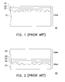
- FIG. 1 is a vertical cross-sectional view of a CD.
- a CD 100 has a thickness of about 1.2 mm, and has a recording layer 120 , a reflective layer 130 , and a printing layer 140 formed in order on a surface of a pre-grooved substrate 110 .
- FIG. 2 is a vertical cross-sectional view of a DVD.
- a DVD 200 includes a dummy substrate 250 with a thickness of 0.6 mm, and a data substrate with a thickness of 0.6 mm.
- the two substrates are adhered to each other by an adhering layer 240 to form an optical disk with a thickness of 1.2 mm.
- the data substrate has a pre-grooved substrate 210 as a base, and a recording layer 220 and a reflective layer 230 are formed thereon in order.
- a pickup head of the optical drive must emit laser beams of different power levels, and read data using different methods. Therefore before reading data, the optical drive must determine the disk type and employ a suitable reading method to correctly read data recorded thereon.
- determining the type of a disk placed in an optical drive is achieved by calculating the reflection time of the laser beam.
- the laser beam is emitted from a pickup head onto a data area of a disk.
- the laser beam reaches the surface of the disk, it produces a reflective signal (note that many pits are formed on the surface of a reflective layer); while when the laser beam reaches the reflective layer of the disk, it also produces a reflective signal.
- a time difference between the two reflective signals is compared with a predetermined critical value to determine the disk type. As shown in FIG. 1 and FIG.
- the substrate 110 of the CD 100 is thicker than the substrate 210 of the DVD 200 , and therefore when the laser beam irradiates the CD 100 , the time difference of the reflective signals is larger than that of the DVD 200 .
- the optical drive therefore can determine whether the disk is a CD or a DVD.
- the laser beam irradiates the data area of the disk where data is stored, while the pits formed by burning or etching are formed on the substrate of the disk in the data area.
- the pits make the reflected light scatter or diffract, and a depth difference between a land area and a pit area on the disk makes the time difference of the reflective signals produce errors. Therefore, the optical drive may misdetermine the disk type because of the errors to fail to read data stored in the disk correctly.
- an objective of the invention is to provide a method for determining a disk type by moving a pickup head to a blank area with no data, so that misdetermining the disk type due to the depth of the pits can be avoided.
- the invention provides a method for determining a disk type of a digital versatile disk (DVD) optical drive.
- the DVD optical drive includes a pickup head, a spindle motor, and a stepping motor, and is suitable for accommodating a disk.
- the method for determining a disk type includes the following steps. First, the pickup head is moved to a blank area of the disk where no data is stored. After rotation of the disk is stopped, the blank area is irradiated with a laser beam in a first wavelength, and a first time interval for the laser beam to reflect from a surface of the blank area to the pickup head, and a second time interval for the laser beam to reflect from a reflective layer of the blank area to the pickup head, are both measured. A time difference between the first time interval and the second time interval is calculated, and then the time difference is compared with a reference value to determine the disk type.
- the spindle motor may be rotated for a first time period to determine whether the disk is placed properly.
- the step of moving the pickup head to the blank area of the disk where no data is stored may further include the following steps.
- the pickup head is moved in a direction toward the center of the disk until the pickup head reaches a dead position. Then, the disk is rotated at a first speed, and the pickup head is turned on to irradiate the disk with the laser beam. Tracking is performed to move the pickup head along a track at a second speed toward a direction away from the center.
- a high-frequency reflective signal reflected from the disk is received and processed to determine whether the reflective signal is at a high level or a low level.
- a first time point when the low level initially occurs is calculated; then after over a third time interval from the first time point, the moving of the pickup head is stopped; and the pickup head is moved at the second speed in the direction toward the center over a fourth time interval which is longer than the third time interval.
- the step of determining whether the high-frequency reflective signal is at the high level or the low level may further include the high-frequency reflective signal being at the high level when a land area is irradiated with the laser beam and the high-frequency reflective signal being at the low level when a pit area is irradiated with the laser beam.
- the dead position may be the position closest to the center of the disk that the pickup head can reach.
- the step of tracking to move the pickup head along the track at the second speed toward the direction away from the center may further include: using a spectroscope to divide the laser beam so that a primary spot and two secondary spots appear when the laser beam irradiates the disk.
- a plurality of reflected light of the spots may be received by photo detectors of the pickup head to advance or retreat the primary spot along a predetermined track of the disk according to the amount of reflection of the reflected light.
- the step of determining whether the high-frequency reflective signal is at the high level or the low level may further include comparing the amount of the reflection of the reflected light with a default value. If the amount of the reflection is larger than the default value, the high-frequency reflective signal is at the high level; if the amount of the reflection is smaller than the default value, the high-frequency reflective signal is at the low level.
- the step of stopping moving the pickup head after over the third time interval from the first time point may further include according to a clock signal produced by a clock circuit wherein the clock signal includes a plurality of the same pulse unit, comparing the high-frequency reflective signal with the clock signal to calculate relationship between the third time interval and the pulse unit.
- the step of moving the pickup head at the second speed in the direction toward the center over the fourth time interval longer than the third time interval may further include continuously accumulating the same pulse unit to be equal to the fourth time interval according to a clock signal produced by a clock circuit.
- a testing area may be closest to the center and a data area may be in an outer periphery of the testing area.
- a program memory area may be in a peripheral area of the testing area, and the blank area may be in an inner periphery of the PMA.
- a track may extend from the testing area to the data area along a spiral curve.
- the pickup head is moved to the blank area of the disk where no data is stored; then the surface and the reflective layer of the blank area are irradiated with the laser beam, and the difference in the reflection time of the laser beam is calculated to determine the disk type. Therefore, misdetermining the disk type because of effects of the pits in the data area on the reflection of the laser beam can be reduced.
- the pickup head of the DVD optical drive is moved to the blank area of the disk where no data is stored, and the time for the laser beam to reflect to the surface layer and the reflective layer of the blank area is calculated respectively to determine the type of the disk placed in the DVD optical drive. Therefore misdetermining the disk type to fail to read disk data because of the effects of the pits in the data area of the disk on the reflective signals can be avoided.
- FIG. 1 is a vertical cross-sectional view of parts of a data area of a compact disk (CD).
- FIG. 2 is a vertical cross-sectional view of parts of a data area of a digital versatile disk (DVD).
- DVD digital versatile disk
- FIG. 3 is a flow chart showing a method for determining a disk type according to a preferred embodiment of the invention.
- FIG. 4 is a horizontal cross-sectional view of a disk.
- FIG. 5 is a flow chart showing moving a pickup head to a blank area of a disk according to a preferred embodiment.
- FIG. 6 is a vertical cross-sectional view of parts of a program memory area (PMA).
- PMA program memory area
- a pickup head is moved to a blank area of the disk where no data is stored to determine the disk type. Misjudgment therefore can be avoided effectively.
- FIG. 3 is a flow chart showing a method for determining a disk type according to a preferred embodiment of the invention.
- This embodiment takes a digital versatile disk (DVD) optical drive suitable for accommodating a disk as an example to explain detailed steps for determining the disk type.
- the DVD optical drive includes a pickup head, a spindle motor, a stepping motor, and so on. By this method, the DVD optical drive can determine whether the disk placed therein is a compact disk (CD) or a DVD.
- CD compact disk
- DVD digital versatile disk
- the pickup head of the DVD optical drive is moved to a blank area of the disk where no data is stored (step 310 ).
- FIG. 4 is a horizontal cross-sectional view of a disk.
- a disk 400 includes a blank area, a program memory area (PMA), and a data area, while combination of the blank area and the PMA is called a testing area.
- the blank area is closest to a center 410 and is suitable for receiving laser beams for trial writing when power calibration is performed;
- the PMA is in an outer periphery of the blank area and is mainly for recording a table of content (TOC) of the disk;
- the data area is in the most outer periphery and is for recording data that a user wants to store on the disk.
- the pickup head is moved to the blank area, and in order to clearly explain the detailed steps of moving the pickup head to the blank area, another embodiment is provided for further explanation.
- FIG. 5 is a flow chart showing moving a pickup head to a blank area of a disk according to a preferred embodiment. Please referring to FIG. 4 and FIG. 5 together, first, in step 510 , the pickup head is moved in a direction toward the center 410 of the disk 400 until the pickup head reaches a dead position.
- the dead position may be the position closest to the center 410 of the disk 400 that the pickup head driven by the stepping motor can reach.
- the disk 400 is rotated at a first speed (step 520 ).
- the pickup head is turned on to irradiate the disk 400 with the laser beam (step 530 ).
- the stepping motor drives the pickup head to track to move the pickup head along a track of the disk 400 at a second speed toward a direction away from the center 410 .
- the track of the disk 400 extends from the testing area to the data area along a spiral curve, and the first speed and the second speed are both uniform speeds.
- tracking is to assure that the emitted laser beam can follow the track of the disk 400 accurately when the pickup head moves.
- Tracking employs conventional techniques in the art, such as the three-beam method.
- a spectroscope is used to divide the laser beam irradiating the disk 400 into a primary spot and two secondary spots; reflected light of the spots is received by photo detectors of the pickup head; the primary spot is made advance or retreat along the track of the disk 400 according to the amount of the reflections of the two secondary spots and calculation results thereof.
- FIG. 6 is a vertical cross-sectional view of parts of a PMA.
- the PMA 600 includes a land area 610 , a land area 630 , a land area 650 , a pit area 620 , and a pit area 640 .
- the high-frequency reflective signal after reflection is strong, and therefore the high-frequency reflective signal is at the high level; on the other hand, if the laser beam irradiates the pit areas of the PMA 600 (such as the pit area 620 ), the high-frequency reflective signal after reflection is weak, and therefore the high-frequency reflective signal is at the low level.
- the amount of the reflection of the reflected light is compared with a default value. If the amount of the reflection is larger than the default value, the high-frequency reflective signal is at the high level; if the amount of the reflection is smaller than the default value, the high-frequency reflective signal is at the low level.
- the default value can be pre-recorded in Read Only Memory (ROM) of the DVD optical drive.
- the time point when the high-frequency reflective signal is at the low level for the first time is calculated (step 570 ).
- the time point when the high-frequency reflective signal is at the low level for the first time is when the pickup head moves to a first pit area 420 of the innermost periphery of the disk 400 .
- this time point is referred to as a first time point.
- Next step is moving the pickup head from the first time point for a third time interval (step 580 ).
- the method for calculating the third time interval includes using a clock signal produced by a clock circuit, wherein the clock signal includes a plurality of the same pulse unit. Then the high-frequency reflective signal is compared with the clock signal to calculate relationship between the third time interval and the pulse unit (that is, how much pulse unit the third time interval is equal to).
- the moving speed of the pickup head (the second speed) is a uniform speed. Therefore if only the time period until the pickup head stops from the first time point is calculated (that is, the number of the passed pulse unit), the total distances the pickup head moves can be calculated.
- the pickup head is driven by the stepping motor to move at the second speed in the direction toward the center 410 .
- the moving of the pickup head is stopped (step 590 ).
- the embodiment also includes: according to a clock signal produced by a clock circuit, continuously accumulating pulse unit when the pickup head is moved, and then stopping moving the pickup head until the amount of the pulse unit is equal to the fourth time interval.
- the fourth time interval is longer than the third time interval to assure that the pickup head is moved out of the data area of the disk.
- the fourth time interval should be one to five seconds longer than the third time interval and can be adjusted according to the form of the stepping motor.
- the pickup head may stop on the blank area of the disk 400 where no data is stored to avoid interference from the pits of the data area.
- output signals of the stepping motor can be measured.
- a first number of rotating until the stepping motor stops rotating from the first time point can be calculated.
- the stepping motor is ordered to rotate round for a second number of rotating larger than the first number of rotating to assure that the pickup head can stop on the blank area of the disk 400 where no data is stored.
- the spindle motor stops rotating the disk (step 320 ) and the laser beam in a first wavelength irradiates the blank area (step 330 ).
- a first time interval for the laser beam to reflect from a surface of the blank area to the pickup head and a second time interval for the laser beam to reflect from a reflective layer of the blank to the pickup head area are measured (step 340 ); a time difference between the first time interval and the second time interval is calculated (step 350 ); then the time difference is compared with a reference value to determine the disk type (step 360 ), wherein the reference value can be pre-recorded in memory of the DVD optical drive.
- the disk structure of the CD and the DVD when the laser beam irradiates the blank area of the CD, a difference between the first time interval for the reflection of the surface and the second time interval for the reflection of the reflective layer is longer than that of the DVD. Therefore, whether the disk in the DVD optical drive is a CD or a DVD can be determined by comparing the difference with a reference value.
Abstract
Description
Claims (10)
Applications Claiming Priority (3)
| Application Number | Priority Date | Filing Date | Title |
|---|---|---|---|
| TW096105462A TWI358065B (en) | 2007-02-14 | 2007-02-14 | Method for determining type of optical disk |
| TW96105462A | 2007-02-14 | ||
| TW96105462 | 2007-02-14 |
Publications (2)
| Publication Number | Publication Date |
|---|---|
| US20080192604A1 US20080192604A1 (en) | 2008-08-14 |
| US7808868B2 true US7808868B2 (en) | 2010-10-05 |
Family
ID=39685697
Family Applications (1)
| Application Number | Title | Priority Date | Filing Date |
|---|---|---|---|
| US12/023,040 Active 2029-04-02 US7808868B2 (en) | 2007-02-14 | 2008-01-31 | Method for determining disk type |
Country Status (2)
| Country | Link |
|---|---|
| US (1) | US7808868B2 (en) |
| TW (1) | TWI358065B (en) |
Citations (5)
| Publication number | Priority date | Publication date | Assignee | Title |
|---|---|---|---|---|
| US5587981A (en) | 1995-09-05 | 1996-12-24 | Kamatani; Yasuo | Multi-standard optical disk reading method having distinction process |
| US6044048A (en) * | 1996-01-24 | 2000-03-28 | Sony Corporation | Optical pickup and optical disc device for accessing media of differing recording densities |
| US20060007812A1 (en) * | 2004-07-09 | 2006-01-12 | Sony Corporation | Optical pickup device, recorder and/or reproducer |
| US20060018214A1 (en) * | 2004-07-21 | 2006-01-26 | Konica Minolta Opto, Inc. | Assembly method of optical pickup and optical pickup apparatus |
| US20060164954A1 (en) * | 2005-01-20 | 2006-07-27 | Konica Minolta Opto, Inc. | Optical pickup apparatus |
-
2007
- 2007-02-14 TW TW096105462A patent/TWI358065B/en active
-
2008
- 2008-01-31 US US12/023,040 patent/US7808868B2/en active Active
Patent Citations (5)
| Publication number | Priority date | Publication date | Assignee | Title |
|---|---|---|---|---|
| US5587981A (en) | 1995-09-05 | 1996-12-24 | Kamatani; Yasuo | Multi-standard optical disk reading method having distinction process |
| US6044048A (en) * | 1996-01-24 | 2000-03-28 | Sony Corporation | Optical pickup and optical disc device for accessing media of differing recording densities |
| US20060007812A1 (en) * | 2004-07-09 | 2006-01-12 | Sony Corporation | Optical pickup device, recorder and/or reproducer |
| US20060018214A1 (en) * | 2004-07-21 | 2006-01-26 | Konica Minolta Opto, Inc. | Assembly method of optical pickup and optical pickup apparatus |
| US20060164954A1 (en) * | 2005-01-20 | 2006-07-27 | Konica Minolta Opto, Inc. | Optical pickup apparatus |
Also Published As
| Publication number | Publication date |
|---|---|
| US20080192604A1 (en) | 2008-08-14 |
| TWI358065B (en) | 2012-02-11 |
| TW200834566A (en) | 2008-08-16 |
Similar Documents
| Publication | Publication Date | Title |
|---|---|---|
| RU2343568C2 (en) | Data carrier and method of recording thereon | |
| US7936653B2 (en) | Information processing device, access device, recording medium, information processing method, and information processing program | |
| JP3989665B2 (en) | Optical information recording medium | |
| JP4203509B2 (en) | Optical disc apparatus and disc discrimination method | |
| JP4226184B2 (en) | Information recording medium discriminating apparatus and information recording medium discriminating method | |
| US7760603B2 (en) | Apparatus and method for discriminating optical disc type | |
| US20080151730A1 (en) | Optical recording and reading method, optical recording and reading apparatus, and optical recording medium | |
| US7808868B2 (en) | Method for determining disk type | |
| JP2005056543A (en) | Method for identifying type of two-layer disk and optical disk device | |
| CN101246711B (en) | Disc kind discrimination method | |
| JP3717921B2 (en) | Recording device | |
| JP3996339B2 (en) | Optical recording / reproducing apparatus, optical disc discrimination method, and optical recording / reproducing apparatus start-up method | |
| JP2006099914A (en) | Optical disk recording method and optical disk recording and reproducing device | |
| WO2005081241A1 (en) | Optical information recording medium and information recording/reproduction device | |
| JP2001034941A (en) | Optical disk device and discriminating method thereof | |
| JP2005038514A (en) | Discriminating device of optical disk | |
| JP2004310970A (en) | Optical disk drive | |
| JP2007172834A (en) | Recorder and recording method | |
| JP2006164417A (en) | Optical disk device | |
| JP2000090450A (en) | Focus bias setting device | |
| JP2008299898A (en) | Disk apparatus | |
| JP2005182984A (en) | Method and device for recording information on optical information recording medium, and optical information recording medium | |
| JP2006099829A (en) | Optical disk device and control method therefor | |
| JP2008135111A (en) | Optical disk device and optical disk playback method | |
| JP2008186508A (en) | Optical disk device and optical disk recording and reproducing method |
Legal Events
| Date | Code | Title | Description |
|---|---|---|---|
| AS | Assignment |
Owner name: ASUSTEK COMPUTER INC., TAIWAN Free format text: ASSIGNMENT OF ASSIGNORS INTEREST;ASSIGNOR:LU, KUO-PING;REEL/FRAME:020579/0163 Effective date: 20080114 |
|
| STCF | Information on status: patent grant |
Free format text: PATENTED CASE |
|
| FPAY | Fee payment |
Year of fee payment: 4 |
|
| MAFP | Maintenance fee payment |
Free format text: PAYMENT OF MAINTENANCE FEE, 8TH YEAR, LARGE ENTITY (ORIGINAL EVENT CODE: M1552) Year of fee payment: 8 |
|
| MAFP | Maintenance fee payment |
Free format text: PAYMENT OF MAINTENANCE FEE, 12TH YEAR, LARGE ENTITY (ORIGINAL EVENT CODE: M1553); ENTITY STATUS OF PATENT OWNER: LARGE ENTITY Year of fee payment: 12 |