US7814643B2 - Method for reducing off-track gain for a disk drive actuator - Google Patents
Method for reducing off-track gain for a disk drive actuator Download PDFInfo
- Publication number
- US7814643B2 US7814643B2 US11/750,639 US75063907A US7814643B2 US 7814643 B2 US7814643 B2 US 7814643B2 US 75063907 A US75063907 A US 75063907A US 7814643 B2 US7814643 B2 US 7814643B2
- Authority
- US
- United States
- Prior art keywords
- pivot
- comb
- coil
- actuator
- nodal point
- Prior art date
- Legal status (The legal status is an assumption and is not a legal conclusion. Google has not performed a legal analysis and makes no representation as to the accuracy of the status listed.)
- Expired - Fee Related, expires
Links
Images


Classifications
-
- G—PHYSICS
- G11—INFORMATION STORAGE
- G11B—INFORMATION STORAGE BASED ON RELATIVE MOVEMENT BETWEEN RECORD CARRIER AND TRANSDUCER
- G11B5/00—Recording by magnetisation or demagnetisation of a record carrier; Reproducing by magnetic means; Record carriers therefor
- G11B5/48—Disposition or mounting of heads or head supports relative to record carriers ; arrangements of heads, e.g. for scanning the record carrier to increase the relative speed
- G11B5/4806—Disposition or mounting of heads or head supports relative to record carriers ; arrangements of heads, e.g. for scanning the record carrier to increase the relative speed specially adapted for disk drive assemblies, e.g. assembly prior to operation, hard or flexible disk drives
- G11B5/4833—Structure of the arm assembly, e.g. load beams, flexures, parts of the arm adapted for controlling vertical force on the head
-
- G—PHYSICS
- G11—INFORMATION STORAGE
- G11B—INFORMATION STORAGE BASED ON RELATIVE MOVEMENT BETWEEN RECORD CARRIER AND TRANSDUCER
- G11B5/00—Recording by magnetisation or demagnetisation of a record carrier; Reproducing by magnetic means; Record carriers therefor
- G11B5/48—Disposition or mounting of heads or head supports relative to record carriers ; arrangements of heads, e.g. for scanning the record carrier to increase the relative speed
- G11B5/54—Disposition or mounting of heads or head supports relative to record carriers ; arrangements of heads, e.g. for scanning the record carrier to increase the relative speed with provision for moving the head into or out of its operative position or across tracks
- G11B5/55—Track change, selection or acquisition by displacement of the head
- G11B5/5521—Track change, selection or acquisition by displacement of the head across disk tracks
- G11B5/5569—Track change, selection or acquisition by displacement of the head across disk tracks details of specially adapted mobile parts, e.g. electromechanical control devices
-
- Y—GENERAL TAGGING OF NEW TECHNOLOGICAL DEVELOPMENTS; GENERAL TAGGING OF CROSS-SECTIONAL TECHNOLOGIES SPANNING OVER SEVERAL SECTIONS OF THE IPC; TECHNICAL SUBJECTS COVERED BY FORMER USPC CROSS-REFERENCE ART COLLECTIONS [XRACs] AND DIGESTS
- Y10—TECHNICAL SUBJECTS COVERED BY FORMER USPC
- Y10T—TECHNICAL SUBJECTS COVERED BY FORMER US CLASSIFICATION
- Y10T29/00—Metal working
- Y10T29/49—Method of mechanical manufacture
- Y10T29/49002—Electrical device making
- Y10T29/4902—Electromagnet, transformer or inductor
- Y10T29/49021—Magnetic recording reproducing transducer [e.g., tape head, core, etc.]
- Y10T29/49025—Making disc drive
-
- Y—GENERAL TAGGING OF NEW TECHNOLOGICAL DEVELOPMENTS; GENERAL TAGGING OF CROSS-SECTIONAL TECHNOLOGIES SPANNING OVER SEVERAL SECTIONS OF THE IPC; TECHNICAL SUBJECTS COVERED BY FORMER USPC CROSS-REFERENCE ART COLLECTIONS [XRACs] AND DIGESTS
- Y10—TECHNICAL SUBJECTS COVERED BY FORMER USPC
- Y10T—TECHNICAL SUBJECTS COVERED BY FORMER US CLASSIFICATION
- Y10T29/00—Metal working
- Y10T29/49—Method of mechanical manufacture
- Y10T29/49002—Electrical device making
- Y10T29/4902—Electromagnet, transformer or inductor
- Y10T29/49021—Magnetic recording reproducing transducer [e.g., tape head, core, etc.]
- Y10T29/49027—Mounting preformed head/core onto other structure
Definitions
- the present invention relates in general to improved performance for a disk drive actuator and, in particular, to an improved system, method, and apparatus for reducing off-track gain for the second primary resonance of a disk drive actuator in the off-track direction.
- Data access and storage systems generally comprise one or more storage devices that store data on magnetic or optical storage media.
- a magnetic storage device is known as a direct access storage device (DASD) or a hard disk drive (HDD) and includes one or more disks and a disk controller to manage local operations concerning the disks.
- the hard disks themselves are usually made of aluminum alloy or a mixture of glass and ceramic, and are covered with a magnetic coating.
- one to five disks are stacked vertically on a common spindle that is turned by a disk drive motor at several thousand revolutions per minute (rpm).
- Hard disk drives have several different typical standard sizes or formats, including server, desktop, mobile (2.5 and 1.8 inches) and microdrive.
- a typical HDD also uses an actuator assembly to move magnetic read/write heads to the desired location on the rotating disk so as to write information to or read data from that location.
- the magnetic read/write head is mounted on a slider.
- a slider generally serves to mechanically support the head and any electrical connections between the head and the rest of the disk drive system.
- the slider is aerodynamically shaped to glide over moving air in order to maintain a uniform distance from the surface of the rotating disk, thereby preventing the head from undesirably contacting the disk.
- a slider is typically formed with an aerodynamic pattern of protrusions on its air bearing surface (ABS) that enables the slider to fly at a constant height close to the disk during operation of the disk drive.
- ABS air bearing surface
- a slider is associated with each side of each disk and flies just over the disk's surface.
- Each slider is mounted on a suspension to form a head gimbal assembly (HGA).
- HGA head gimbal assembly
- the HGA is then attached to a semi-rigid actuator arm that supports the entire head flying unit.
- Several semi-rigid arms may be combined to form a single movable unit having a rotary pivotal bearing system.
- the head and arm assembly is pivotally moved utilizing a magnet/coil structure that is often called a voice coil motor (VCM).
- VCM voice coil motor
- the stator of a VCM is mounted to a base plate or casting on which the spindle is also mounted.
- the base casting with its spindle, actuator VCM, and internal filtration system is then enclosed with a cover and seal assembly to ensure that no contaminants can enter and adversely affect the reliability of the slider flying over the disk.
- the VCM develops force or torque that is substantially proportional to the applied current.
- the arm acceleration is therefore substantially proportional to the magnitude of the current.
- a reverse polarity signal is applied to the actuator, causing the signal to act as a brake, and ideally causing the read/write head to stop and settle directly over the desired track.
- the motor used to rotate the disk is typically a brushless DC motor.
- the disk is mounted and clamped to a hub of the motor.
- the hub provides a disk mounting surface and a means to attach an additional part or parts to clamp the disk to the hub.
- the rotating part of the motor (the rotor) is attached to or is an integral part of the hub.
- the rotor includes a ring-shaped magnet with alternating north/south poles arranged radially and a ferrous metal backing.
- the magnet interacts with the motor's stator by means of magnetic forces. Magnetic fields and resulting magnetic forces are induced via the electric current in the coiled wire of the motor stator.
- the ferrous metal backing of the rotor acts as a magnetic return path.
- the rotor magnet magnetic pole pattern should not be substantially altered after it is magnetically charged during the motor's manufacturing process.
- One embodiment of a system, method, and apparatus for a disk drive actuator with improved dynamics is disclosed.
- the dynamics of the actuator are enhanced by redistributing the mass and stiffness of the structure. In one version, this is accomplished by relocating the two nodal points of the second primary bending mode of the actuator at specific positions.
- One nodal point is positioned as close to the read-write head as possible at one end of the actuator, and the other nodal point is positioned at the center of the active legs of the VCM coil at the other end of the actuator. This is done to reduce the off-track displacement associated with this fundamental resonance to near zero, allowing higher track densities to be supported.
- This solution has the added advantage of having low sensitivity to the variations in actuator fabrication that occur in high volume production. Since nodes are positioned at the input and output ends for the device, they tend to cancel each other when random variations in the construction of the actuator occur.
- the mount plates of the suspension system were increased in axial thickness by about 25%. This modification moved the point of rotation for the nodal point on the head side of the actuator toward the recording head by several millimeters, which also reduces the off-track amplitude. Ideally, the point of rotation is positioned exactly at the read/write head, but in practice this is not possible without positioning mass beyond the read/write head. Such a solution is undesirable in most cases due to packing constraints.
- FIG. 1 is a plan view of a disk drive constructed in accordance with the present invention.
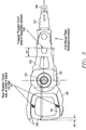
- FIG. 2 is an isometric view of an actuator for the disk drive of FIG. 1 and is constructed in accordance with the present invention.
- FIG. 3 is a plan view of the actuator of FIG. 2 and is constructed in accordance with the present invention.
- FIG. 1 a schematic drawing of one embodiment of an information storage system comprising a magnetic hard disk file or drive 111 for a computer system is shown.
- Drive 111 has an outer housing or base 113 containing at least one magnetic disk 115 .
- Disk 115 is rotated by a spindle motor assembly having a central drive hub 117 .
- An actuator 121 comprises a plurality of parallel actuator arms 125 (one shown) in the form of a comb that is pivotally mounted to base 113 about a pivot assembly 123 .
- a controller 119 is also mounted to base 113 for selectively moving the comb of arms 125 relative to disk 115 .
- each arm 125 has extending from it at least one cantilevered load beam and suspension 127 .
- a magnetic read/write transducer or head is mounted on a slider 129 and secured to a flexure that is flexibly mounted to each suspension 127 .
- the read/write heads magnetically read data from and/or magnetically write data to disk 115 .
- the level of integration called the head gimbal assembly is head and the slider 129 , which are mounted on suspension 127 .
- the slider 129 is usually bonded to the end of suspension 127 .
- the head is typically pico size (approximately 1250 ⁇ 1000 ⁇ 300 microns) and formed from ceramic or intermetallic materials.
- the head also may be femto size (approximately 850 ⁇ 700 ⁇ 230 microns) and is pre-loaded against the surface of disk 115 (in the range two to ten grams) by suspension 127 .
- Suspensions 127 have a spring-like quality which biases or urges the air bearing surface of the slider 129 against the disk 115 to enable the creation of the air bearing film between the slider 129 and disk surface.
- a voice coil 133 housed within a conventional voice coil motor magnet assembly 134 (top pole not shown) is also mounted to arms 125 opposite the head gimbal assemblies. Movement of the actuator 121 (indicated by arrow 135 ) by controller 119 moves the head gimbal assemblies radially across tracks on the disk 115 until the heads settle on their respective target tracks.
- the head gimbal assemblies operate in a conventional manner and always move in unison with one another, unless drive 111 uses multiple independent actuators (not shown) wherein the arms can move independently of one another.
- the actuator 121 includes a comb 141 having a pivot bore 143 , a set of comb legs 145 (two shown) extending from the comb 141 on one side of the pivot bore 143 , and an arm 125 (several shown) extending from the comb 141 opposite the active legs 145 .
- the pivot 123 is mounted in the pivot bore 143 of the comb 141 and has an axis 147 of rotation.
- At least one head gimbal assembly 127 is mounted to each arm 124 of the comb 141 and has a read/write head 149 .
- the coil 133 for the voice coil motor is mounted to the comb 141 between the comb legs 145 .
- the coil 133 has a set of active legs 151 (two shown) that extend radially relative to axis 147 .
- a first nodal point 153 of rotation of a second primary bending mode of the disk drive actuator assembly is positioned further away ( ⁇ x) from axis 147 , which is further adjacent the read/write head 149 .
- the first nodal point 153 is positioned as close to the read/write head 149 as possible to reduce vibration at the second primary bending mode.
- One way to accomplish this objective is to increase an axial thickness 155 ( FIG. 2 ) of the mount plate of the head gimbal assembly 127 by about 25% over the nominal design to position the first nodal point 153 away from the axis several millimeters further toward the read/write head 149 .
- a second nodal point 161 of rotation of the second primary bending mode is positioned at a geometric center of the active legs 145 of the coil 133 .
- the first and second nodal points 153 , 161 reduce off-track gain for the second primary bending mode in an off-track direction. In one version, this may be accomplished, relative to the pivot axis 147 , by reducing an axial thickness 165 ( FIG. 2 ) of the coil 133 , and increasing a radial length 167 of the coil 133 ( ⁇ y) to position the second nodal point 161 away from the axis 147 by several millimeters to the geometric center of the active legs of the coil 133 .
- One embodiment of the present invention also comprises a method of redefining the nodal points of rotation in a disk drive actuator assembly to improve the dynamics thereof.
- the method comprises providing an actuator assembly 121 with a comb 141 , a pivot 123 mounted in the comb 141 having an axis 147 of rotation, comb legs 145 extending from the comb 141 on one side of the pivot 123 .
- the actuator assembly 121 also has a coil 133 of a voice coil motor mounted thereto, an arm 125 extending from the comb 141 opposite the comb legs 145 , and a head gimbal assembly 127 mounted to the arm 125 and having a read/write head 149 opposite the arm 125 .
- the method further comprises defining a first nodal point 153 of rotation for the actuator assembly 121 at a position that is on the arm 125 between the pivot 123 and the read/write head 149 ; defining a second nodal point 161 of rotation for the actuator assembly 121 at a position that is adjacent to the pivot 123 and the coil 133 ; moving the first nodal point 153 in a radial direction away from the pivot axis 147 toward the read/write head 149 ; and moving the second nodal point 161 in a radial direction away from the pivot axis 147 to a geometric center of the active legs 151 of the coil 133 , such that the moved first and second nodal points 153 , 161 reduce vibration when operational forces are imparted on the actuator assembly 121 by the voice coil motor during seek events to reduce off-track amplitude of the read/write head 149 .
- the method may comprise increasing an axial thickness 155 of the head gimbal assembly to move the first nodal point 153 several millimeters ( ⁇ x) toward the read/write head 149 .
- the method may comprise lengthening the coil 133 several millimeters ( ⁇ y) in a radial direction and reducing an axial thickness 165 of the coil 133 to reduce its mass.
- the present invention has several advantages, including the ability to improve the dynamics of disk drive actuators.
- the solution presented has low sensitivity to the variations in actuator fabrication that occur in high volume production.
- the nodes are positioned at the input and output ends of the device and tend to cancel each other when random variations in the construction of the actuator occur.
- there are no increases in cost or complexity are associated with its implementation.
- the design of existing actuator systems is carefully re-configured to manipulate the mode shape in a manner that reduces off-track amplitude.
Abstract
Description
Claims (3)
Priority Applications (1)
| Application Number | Priority Date | Filing Date | Title |
|---|---|---|---|
| US11/750,639 US7814643B2 (en) | 2004-06-30 | 2007-05-18 | Method for reducing off-track gain for a disk drive actuator |
Applications Claiming Priority (2)
| Application Number | Priority Date | Filing Date | Title |
|---|---|---|---|
| US10/881,164 US7239486B2 (en) | 2004-06-30 | 2004-06-30 | System and apparatus for reducing off-track gain for a disk drive actuator |
| US11/750,639 US7814643B2 (en) | 2004-06-30 | 2007-05-18 | Method for reducing off-track gain for a disk drive actuator |
Related Parent Applications (1)
| Application Number | Title | Priority Date | Filing Date |
|---|---|---|---|
| US10/881,164 Division US7239486B2 (en) | 2004-06-30 | 2004-06-30 | System and apparatus for reducing off-track gain for a disk drive actuator |
Publications (2)
| Publication Number | Publication Date |
|---|---|
| US20080106822A1 US20080106822A1 (en) | 2008-05-08 |
| US7814643B2 true US7814643B2 (en) | 2010-10-19 |
Family
ID=35513616
Family Applications (2)
| Application Number | Title | Priority Date | Filing Date |
|---|---|---|---|
| US10/881,164 Expired - Fee Related US7239486B2 (en) | 2004-06-30 | 2004-06-30 | System and apparatus for reducing off-track gain for a disk drive actuator |
| US11/750,639 Expired - Fee Related US7814643B2 (en) | 2004-06-30 | 2007-05-18 | Method for reducing off-track gain for a disk drive actuator |
Family Applications Before (1)
| Application Number | Title | Priority Date | Filing Date |
|---|---|---|---|
| US10/881,164 Expired - Fee Related US7239486B2 (en) | 2004-06-30 | 2004-06-30 | System and apparatus for reducing off-track gain for a disk drive actuator |
Country Status (1)
| Country | Link |
|---|---|
| US (2) | US7239486B2 (en) |
Cited By (3)
| Publication number | Priority date | Publication date | Assignee | Title |
|---|---|---|---|---|
| US20090021865A1 (en) * | 2007-07-20 | 2009-01-22 | Bernhard Knigge | Minimizing slider vibration effects on a magnetic transducer |
| US8830634B2 (en) | 2012-05-31 | 2014-09-09 | HGST Netherlands B.V. | Asymmetric comb bore in actuator design |
| US20160284369A1 (en) * | 2015-03-25 | 2016-09-29 | Guzik Technical Enterprises | Head gimbal assembly (hga) support cartridge for magnetic head and disk testers |
Families Citing this family (1)
| Publication number | Priority date | Publication date | Assignee | Title |
|---|---|---|---|---|
| JP4709083B2 (en) * | 2006-07-05 | 2011-06-22 | 日本発條株式会社 | Disk unit |
Citations (23)
| Publication number | Priority date | Publication date | Assignee | Title |
|---|---|---|---|---|
| JPS6077662A (en) | 1983-09-30 | 1985-05-02 | Toshiba Corp | Rockable actuator |
| JPH0255558A (en) | 1988-08-18 | 1990-02-23 | Fuji Electric Co Ltd | Head controlling actuator of disc memory |
| US5027241A (en) | 1989-06-01 | 1991-06-25 | Quantum Corporation | Data head load beam for height compacted, low power fixed head and disk assembly |
| JPH04216376A (en) | 1990-12-17 | 1992-08-06 | Mitsubishi Electric Corp | Head positioning mechanism for fixed magnetic disk device |
| JPH06251518A (en) | 1992-12-29 | 1994-09-09 | Sony Corp | Actuator |
| US5764441A (en) | 1995-04-28 | 1998-06-09 | Fujitsu Limited | Head actuator having reduced and controlled vibration characteristics for high speed disk drive systems |
| US5905608A (en) | 1997-09-19 | 1999-05-18 | International Business Machines Corporation | Dynamically tuned outer arms for improved rotary actuator performance |
| US5936808A (en) | 1997-11-24 | 1999-08-10 | International Business Machines Corporation | Disk drive rotary actuator having arm with cross-member containing elastomeric damping member |
| US5953180A (en) | 1997-07-23 | 1999-09-14 | International Business Machines Corporation | Multi-mode suspension populated actuator for a disk drive |
| US5973421A (en) | 1996-04-18 | 1999-10-26 | Nec Corporation | Voice coil motor actuator for magnetic disk device |
| US6034834A (en) | 1995-09-12 | 2000-03-07 | Kabushiki Kaisha Toshiba | Head driving device and method for driving the same for reducing error due to actuator structure vibration |
| JP2000182344A (en) * | 1998-12-17 | 2000-06-30 | Sharp Corp | Suspension |
| US6104581A (en) | 1998-10-05 | 2000-08-15 | International Business Machines Corporation | Dual coil rotary actuator |
| US6157521A (en) * | 1997-09-25 | 2000-12-05 | Nec Corporation | Recording/reproducing head positioning mechanism |
| US6310749B1 (en) | 1997-09-02 | 2001-10-30 | Seagate Technology Llc | Voice coil motor actuator vibration isolator |
| US20030053261A1 (en) | 2001-09-14 | 2003-03-20 | Thia Terang Kongbeng | Bandwidth disc drive actuator |
| US6538853B1 (en) | 1999-09-13 | 2003-03-25 | Maxtor Corporation | E-block having improved resonance characteristics and improved fragility |
| JP2003092862A (en) | 2001-09-18 | 2003-03-28 | Fujikura Ltd | Method for manufacturing coil for actuator |
| US20030081355A1 (en) | 2001-10-25 | 2003-05-01 | Toshihiro Arisaka | Magnetic disk drive and carriage |
| US20030081356A1 (en) | 2001-10-30 | 2003-05-01 | Toshihiko Shimizu | Carriage arm assembly for locating magnetic head, and magnetic disk apparatus using the same |
| US20030090838A1 (en) | 2001-11-14 | 2003-05-15 | Seagate Technology Llc | Resonant frequency separation for an actuator assembly of a disc drive |
| US20030218833A1 (en) | 2001-10-30 | 2003-11-27 | Shin Nagahiro | Carriage arm assembly for magnetic disk drive |
| JP4216376B2 (en) | 1997-09-11 | 2009-01-28 | イーエム マイクロエレクトロニック−マリン ソシエテ アノニム | Communication protocol between a transceiver unit and a transponder or transceiver associated with the unit |
Family Cites Families (1)
| Publication number | Priority date | Publication date | Assignee | Title |
|---|---|---|---|---|
| US6556382B1 (en) * | 1996-03-29 | 2003-04-29 | Hutchinson Technology, Inc. | Mass balancing for optimizing suspension resonance performance |
-
2004
- 2004-06-30 US US10/881,164 patent/US7239486B2/en not_active Expired - Fee Related
-
2007
- 2007-05-18 US US11/750,639 patent/US7814643B2/en not_active Expired - Fee Related
Patent Citations (23)
| Publication number | Priority date | Publication date | Assignee | Title |
|---|---|---|---|---|
| JPS6077662A (en) | 1983-09-30 | 1985-05-02 | Toshiba Corp | Rockable actuator |
| JPH0255558A (en) | 1988-08-18 | 1990-02-23 | Fuji Electric Co Ltd | Head controlling actuator of disc memory |
| US5027241A (en) | 1989-06-01 | 1991-06-25 | Quantum Corporation | Data head load beam for height compacted, low power fixed head and disk assembly |
| JPH04216376A (en) | 1990-12-17 | 1992-08-06 | Mitsubishi Electric Corp | Head positioning mechanism for fixed magnetic disk device |
| JPH06251518A (en) | 1992-12-29 | 1994-09-09 | Sony Corp | Actuator |
| US5764441A (en) | 1995-04-28 | 1998-06-09 | Fujitsu Limited | Head actuator having reduced and controlled vibration characteristics for high speed disk drive systems |
| US6034834A (en) | 1995-09-12 | 2000-03-07 | Kabushiki Kaisha Toshiba | Head driving device and method for driving the same for reducing error due to actuator structure vibration |
| US5973421A (en) | 1996-04-18 | 1999-10-26 | Nec Corporation | Voice coil motor actuator for magnetic disk device |
| US5953180A (en) | 1997-07-23 | 1999-09-14 | International Business Machines Corporation | Multi-mode suspension populated actuator for a disk drive |
| US6310749B1 (en) | 1997-09-02 | 2001-10-30 | Seagate Technology Llc | Voice coil motor actuator vibration isolator |
| JP4216376B2 (en) | 1997-09-11 | 2009-01-28 | イーエム マイクロエレクトロニック−マリン ソシエテ アノニム | Communication protocol between a transceiver unit and a transponder or transceiver associated with the unit |
| US5905608A (en) | 1997-09-19 | 1999-05-18 | International Business Machines Corporation | Dynamically tuned outer arms for improved rotary actuator performance |
| US6157521A (en) * | 1997-09-25 | 2000-12-05 | Nec Corporation | Recording/reproducing head positioning mechanism |
| US5936808A (en) | 1997-11-24 | 1999-08-10 | International Business Machines Corporation | Disk drive rotary actuator having arm with cross-member containing elastomeric damping member |
| US6104581A (en) | 1998-10-05 | 2000-08-15 | International Business Machines Corporation | Dual coil rotary actuator |
| JP2000182344A (en) * | 1998-12-17 | 2000-06-30 | Sharp Corp | Suspension |
| US6538853B1 (en) | 1999-09-13 | 2003-03-25 | Maxtor Corporation | E-block having improved resonance characteristics and improved fragility |
| US20030053261A1 (en) | 2001-09-14 | 2003-03-20 | Thia Terang Kongbeng | Bandwidth disc drive actuator |
| JP2003092862A (en) | 2001-09-18 | 2003-03-28 | Fujikura Ltd | Method for manufacturing coil for actuator |
| US20030081355A1 (en) | 2001-10-25 | 2003-05-01 | Toshihiro Arisaka | Magnetic disk drive and carriage |
| US20030081356A1 (en) | 2001-10-30 | 2003-05-01 | Toshihiko Shimizu | Carriage arm assembly for locating magnetic head, and magnetic disk apparatus using the same |
| US20030218833A1 (en) | 2001-10-30 | 2003-11-27 | Shin Nagahiro | Carriage arm assembly for magnetic disk drive |
| US20030090838A1 (en) | 2001-11-14 | 2003-05-15 | Seagate Technology Llc | Resonant frequency separation for an actuator assembly of a disc drive |
Non-Patent Citations (1)
| Title |
|---|
| J.S. Heath, "Design of a Swinging Arm Actuator for a Disk File", IBM J. Res. Dev., Jul. 1976, pp. 389ff. |
Cited By (5)
| Publication number | Priority date | Publication date | Assignee | Title |
|---|---|---|---|---|
| US20090021865A1 (en) * | 2007-07-20 | 2009-01-22 | Bernhard Knigge | Minimizing slider vibration effects on a magnetic transducer |
| US8169743B2 (en) * | 2007-07-20 | 2012-05-01 | Hitachi Global Storage Technologies, Netherlands B.V. | Minimizing slider vibration effects on a magnetic transducer |
| US8830634B2 (en) | 2012-05-31 | 2014-09-09 | HGST Netherlands B.V. | Asymmetric comb bore in actuator design |
| US20160284369A1 (en) * | 2015-03-25 | 2016-09-29 | Guzik Technical Enterprises | Head gimbal assembly (hga) support cartridge for magnetic head and disk testers |
| US10115420B2 (en) * | 2015-03-25 | 2018-10-30 | Guzik Technical Enterprises | Head gimbal assembly (HGA) support cartridge for magnetic head and disk testers |
Also Published As
| Publication number | Publication date |
|---|---|
| US7239486B2 (en) | 2007-07-03 |
| US20060002029A1 (en) | 2006-01-05 |
| US20080106822A1 (en) | 2008-05-08 |
Similar Documents
| Publication | Publication Date | Title |
|---|---|---|
| US8085508B2 (en) | System, method and apparatus for flexure-integrated microactuator | |
| US6765759B2 (en) | Resonance four piece suspension | |
| US6947260B2 (en) | System and method of damping vibration on coil supports in high performance disk drives with rotary actuators | |
| US7009809B2 (en) | Clamp retention apparatus for rotational disk drive components | |
| US7126787B2 (en) | System and method for hard disk drive with disk clamp annular rim inner wall engaging hub annular recess outer wall | |
| US7814643B2 (en) | Method for reducing off-track gain for a disk drive actuator | |
| US7576954B2 (en) | Symmetric voice coil motor design, assembly methods of constructing same, and hard disk micro drive storage systems including same | |
| US6815850B2 (en) | Flux leakage barrier in fluid bearing for disk drive | |
| US7149052B2 (en) | Screw attachment from exterior of disk drive enclosure for motors with mount bracket screw bolt pattern diameter larger than the motor hub outside diameter | |
| US7239476B2 (en) | System, method, and apparatus for distributing stress with one or more cavities in a disk clamp for disk drive applications | |
| US7012788B2 (en) | Spacer ring for disk drive spindle with load/unload feature, latch feature, and tribological overcoat | |
| US7652843B2 (en) | Completely circumferential motor bracket shroud for motor hub flange outside diameter for hard disk drive | |
| US20030053264A1 (en) | Slider assemblies | |
| US20070115593A1 (en) | HSA with air turbulence preventing structure for HGA, disk drive unit with the same, and manufacturing method thereof | |
| US7012782B2 (en) | Method of attenuating airflow disturbances in a hard disk drive with a circumferential motor bracket shroud for motor hub flange outside diameter | |
| US7024755B2 (en) | Method balancing a disk pack in a hard disk drive | |
| US7262939B2 (en) | System, method, and apparatus for attaching top pole piece of a voice coil motor to a hard disk drive enclosure | |
| US6442002B1 (en) | Stackable, interlocking mounting supports for data storage actuator arm | |
| US6950286B2 (en) | Actuator arm design for reducing power consumption in a disk drive data storage device | |
| US6885118B2 (en) | Balance clip for reducing friction during clip adjustment in spindle motor and hard disk drive balance process | |
| US7035045B2 (en) | Balance clip holder feature on a spindle motor with nickel-teflon coating on balance clips for reducing friction during clip adjustment in balance process | |
| US20060007599A1 (en) | System, method, and apparatus for high performance, four-piece suspension with extended hinge plate | |
| US7155807B2 (en) | Method of centering media disks on the hub of a spindle motor in a hard disk drive | |
| US7283325B2 (en) | Apparatus and system for centering media disks on the hub of a spindle motor in a hard disk drive |
Legal Events
| Date | Code | Title | Description |
|---|---|---|---|
| AS | Assignment |
Owner name: HITACHI GLOBAL STARAGE TECHNOLOGIES NETHERLANDS BV Free format text: ASSIGNMENT OF ASSIGNORS INTEREST;ASSIGNORS:JOHNSON, BRAD VAUGHN, MR.;STACER, DANIEL R., MR.;REEL/FRAME:019314/0929 Effective date: 20040825 |
|
| FEPP | Fee payment procedure |
Free format text: PAYOR NUMBER ASSIGNED (ORIGINAL EVENT CODE: ASPN); ENTITY STATUS OF PATENT OWNER: LARGE ENTITY |
|
| AS | Assignment |
Owner name: HGST, NETHERLANDS B.V., NETHERLANDS Free format text: CHANGE OF NAME;ASSIGNOR:HGST, NETHERLANDS B.V.;REEL/FRAME:029341/0777 Effective date: 20120723 Owner name: HGST NETHERLANDS B.V., NETHERLANDS Free format text: CHANGE OF NAME;ASSIGNOR:HITACHI GLOBAL STORAGE TECHNOLOGIES NETHERLANDS B.V.;REEL/FRAME:029341/0777 Effective date: 20120723 |
|
| FPAY | Fee payment |
Year of fee payment: 4 |
|
| AS | Assignment |
Owner name: WESTERN DIGITAL TECHNOLOGIES, INC., CALIFORNIA Free format text: ASSIGNMENT OF ASSIGNORS INTEREST;ASSIGNOR:HGST NETHERLANDS B.V.;REEL/FRAME:040821/0550 Effective date: 20160831 |
|
| FEPP | Fee payment procedure |
Free format text: MAINTENANCE FEE REMINDER MAILED (ORIGINAL EVENT CODE: REM.) |
|
| LAPS | Lapse for failure to pay maintenance fees |
Free format text: PATENT EXPIRED FOR FAILURE TO PAY MAINTENANCE FEES (ORIGINAL EVENT CODE: EXP.); ENTITY STATUS OF PATENT OWNER: LARGE ENTITY |
|
| STCH | Information on status: patent discontinuation |
Free format text: PATENT EXPIRED DUE TO NONPAYMENT OF MAINTENANCE FEES UNDER 37 CFR 1.362 |
|
| FP | Lapsed due to failure to pay maintenance fee |
Effective date: 20181019 |