US7824184B2 - Integrated central manifold for orthopedic simulator - Google Patents
Integrated central manifold for orthopedic simulator Download PDFInfo
- Publication number
- US7824184B2 US7824184B2 US11/649,961 US64996107A US7824184B2 US 7824184 B2 US7824184 B2 US 7824184B2 US 64996107 A US64996107 A US 64996107A US 7824184 B2 US7824184 B2 US 7824184B2
- Authority
- US
- United States
- Prior art keywords
- coupled
- actuators
- supply
- fluid
- test
- Prior art date
- Legal status (The legal status is an assumption and is not a legal conclusion. Google has not performed a legal analysis and makes no representation as to the accuracy of the status listed.)
- Active, expires
Links
Images


Classifications
-
- G—PHYSICS
- G01—MEASURING; TESTING
- G01N—INVESTIGATING OR ANALYSING MATERIALS BY DETERMINING THEIR CHEMICAL OR PHYSICAL PROPERTIES
- G01N3/00—Investigating strength properties of solid materials by application of mechanical stress
- G01N3/32—Investigating strength properties of solid materials by application of mechanical stress by applying repeated or pulsating forces
-
- A—HUMAN NECESSITIES
- A61—MEDICAL OR VETERINARY SCIENCE; HYGIENE
- A61F—FILTERS IMPLANTABLE INTO BLOOD VESSELS; PROSTHESES; DEVICES PROVIDING PATENCY TO, OR PREVENTING COLLAPSING OF, TUBULAR STRUCTURES OF THE BODY, e.g. STENTS; ORTHOPAEDIC, NURSING OR CONTRACEPTIVE DEVICES; FOMENTATION; TREATMENT OR PROTECTION OF EYES OR EARS; BANDAGES, DRESSINGS OR ABSORBENT PADS; FIRST-AID KITS
- A61F2/00—Filters implantable into blood vessels; Prostheses, i.e. artificial substitutes or replacements for parts of the body; Appliances for connecting them with the body; Devices providing patency to, or preventing collapsing of, tubular structures of the body, e.g. stents
- A61F2/02—Prostheses implantable into the body
- A61F2/30—Joints
- A61F2/46—Special tools or methods for implanting or extracting artificial joints, accessories, bone grafts or substitutes, or particular adaptations therefor
- A61F2/468—Testing instruments for artificial joints
-
- G—PHYSICS
- G01—MEASURING; TESTING
- G01N—INVESTIGATING OR ANALYSING MATERIALS BY DETERMINING THEIR CHEMICAL OR PHYSICAL PROPERTIES
- G01N3/00—Investigating strength properties of solid materials by application of mechanical stress
- G01N3/32—Investigating strength properties of solid materials by application of mechanical stress by applying repeated or pulsating forces
- G01N3/36—Investigating strength properties of solid materials by application of mechanical stress by applying repeated or pulsating forces generated by pneumatic or hydraulic means
-
- A—HUMAN NECESSITIES
- A61—MEDICAL OR VETERINARY SCIENCE; HYGIENE
- A61F—FILTERS IMPLANTABLE INTO BLOOD VESSELS; PROSTHESES; DEVICES PROVIDING PATENCY TO, OR PREVENTING COLLAPSING OF, TUBULAR STRUCTURES OF THE BODY, e.g. STENTS; ORTHOPAEDIC, NURSING OR CONTRACEPTIVE DEVICES; FOMENTATION; TREATMENT OR PROTECTION OF EYES OR EARS; BANDAGES, DRESSINGS OR ABSORBENT PADS; FIRST-AID KITS
- A61F2/00—Filters implantable into blood vessels; Prostheses, i.e. artificial substitutes or replacements for parts of the body; Appliances for connecting them with the body; Devices providing patency to, or preventing collapsing of, tubular structures of the body, e.g. stents
- A61F2/02—Prostheses implantable into the body
- A61F2/30—Joints
- A61F2/44—Joints for the spine, e.g. vertebrae, spinal discs
- A61F2/442—Intervertebral or spinal discs, e.g. resilient
- A61F2/4425—Intervertebral or spinal discs, e.g. resilient made of articulated components
-
- G—PHYSICS
- G01—MEASURING; TESTING
- G01N—INVESTIGATING OR ANALYSING MATERIALS BY DETERMINING THEIR CHEMICAL OR PHYSICAL PROPERTIES
- G01N2203/00—Investigating strength properties of solid materials by application of mechanical stress
- G01N2203/0001—Type of application of the stress
- G01N2203/0005—Repeated or cyclic
-
- G—PHYSICS
- G01—MEASURING; TESTING
- G01N—INVESTIGATING OR ANALYSING MATERIALS BY DETERMINING THEIR CHEMICAL OR PHYSICAL PROPERTIES
- G01N2203/00—Investigating strength properties of solid materials by application of mechanical stress
- G01N2203/0014—Type of force applied
- G01N2203/0016—Tensile or compressive
- G01N2203/0019—Compressive
-
- G—PHYSICS
- G01—MEASURING; TESTING
- G01N—INVESTIGATING OR ANALYSING MATERIALS BY DETERMINING THEIR CHEMICAL OR PHYSICAL PROPERTIES
- G01N2203/00—Investigating strength properties of solid materials by application of mechanical stress
- G01N2203/0014—Type of force applied
- G01N2203/0021—Torsional
-
- G—PHYSICS
- G01—MEASURING; TESTING
- G01N—INVESTIGATING OR ANALYSING MATERIALS BY DETERMINING THEIR CHEMICAL OR PHYSICAL PROPERTIES
- G01N2203/00—Investigating strength properties of solid materials by application of mechanical stress
- G01N2203/0014—Type of force applied
- G01N2203/0023—Bending
-
- G—PHYSICS
- G01—MEASURING; TESTING
- G01N—INVESTIGATING OR ANALYSING MATERIALS BY DETERMINING THEIR CHEMICAL OR PHYSICAL PROPERTIES
- G01N2203/00—Investigating strength properties of solid materials by application of mechanical stress
- G01N2203/003—Generation of the force
- G01N2203/0042—Pneumatic or hydraulic means
- G01N2203/0044—Pneumatic means
-
- G—PHYSICS
- G01—MEASURING; TESTING
- G01N—INVESTIGATING OR ANALYSING MATERIALS BY DETERMINING THEIR CHEMICAL OR PHYSICAL PROPERTIES
- G01N2203/00—Investigating strength properties of solid materials by application of mechanical stress
- G01N2203/003—Generation of the force
- G01N2203/0042—Pneumatic or hydraulic means
- G01N2203/0048—Hydraulic means
-
- G—PHYSICS
- G01—MEASURING; TESTING
- G01N—INVESTIGATING OR ANALYSING MATERIALS BY DETERMINING THEIR CHEMICAL OR PHYSICAL PROPERTIES
- G01N2203/00—Investigating strength properties of solid materials by application of mechanical stress
- G01N2203/0058—Kind of property studied
- G01N2203/0069—Fatigue, creep, strain-stress relations or elastic constants
-
- G—PHYSICS
- G01—MEASURING; TESTING
- G01N—INVESTIGATING OR ANALYSING MATERIALS BY DETERMINING THEIR CHEMICAL OR PHYSICAL PROPERTIES
- G01N2203/00—Investigating strength properties of solid materials by application of mechanical stress
- G01N2203/0058—Kind of property studied
- G01N2203/0089—Biorheological properties
-
- G—PHYSICS
- G01—MEASURING; TESTING
- G01N—INVESTIGATING OR ANALYSING MATERIALS BY DETERMINING THEIR CHEMICAL OR PHYSICAL PROPERTIES
- G01N2203/00—Investigating strength properties of solid materials by application of mechanical stress
- G01N2203/02—Details not specific for a particular testing method
- G01N2203/022—Environment of the test
- G01N2203/0236—Other environments
- G01N2203/0242—With circulation of a fluid
-
- G—PHYSICS
- G01—MEASURING; TESTING
- G01N—INVESTIGATING OR ANALYSING MATERIALS BY DETERMINING THEIR CHEMICAL OR PHYSICAL PROPERTIES
- G01N2203/00—Investigating strength properties of solid materials by application of mechanical stress
- G01N2203/02—Details not specific for a particular testing method
- G01N2203/022—Environment of the test
- G01N2203/0244—Tests performed "in situ" or after "in situ" use
- G01N2203/0246—Special simulation of "in situ" conditions, scale models or dummies
-
- G—PHYSICS
- G01—MEASURING; TESTING
- G01N—INVESTIGATING OR ANALYSING MATERIALS BY DETERMINING THEIR CHEMICAL OR PHYSICAL PROPERTIES
- G01N2203/00—Investigating strength properties of solid materials by application of mechanical stress
- G01N2203/02—Details not specific for a particular testing method
- G01N2203/04—Chucks, fixtures, jaws, holders or anvils
- G01N2203/0464—Chucks, fixtures, jaws, holders or anvils with provisions for testing more than one specimen at the time
- G01N2203/0476—Chucks, fixtures, jaws, holders or anvils with provisions for testing more than one specimen at the time in parallel
Definitions
- the embodiments of the present invention relate to the field of orthopedic simulators, such as spinal implant wear test machines.
- An orthopedic simulator may require extensive routing of the operating fluid for force actuators that apply testing forces to test specimens.
- Operating fluid can be a liquid, such as hydraulic fluid, or a gas such as air.
- the extensive routing can add to the size of the simulator due to the many tubes and connections that are typically required for hydraulic or pneumatic systems. Similar concerns hold true for systems that employ electrical connections and wiring to control the actuators. Further, assembly may be difficult and with multiple connections, there is a relatively high likelihood of leaks. Also, the various mechanical movements of the actuators can cause undesirable vibrations in the simulator during operation.
- an integral central manifold arrangement for an orthopedic simulator comprising a substantially solid block of material forming a manifold housing.
- a fluid tube is provided within the manifold housing, and fluid inlets and outlets are configured to fluidically couple the fluid tube to the orthopedic simulator.
- an orthopedic simulator comprising a plurality of test stations, a plurality of actuators coupled to the test stations, and support components that support the test stations.
- An integral manifold is provided that is structurally coupled to the support components and is fluidically coupled to the plurality of actuators.
- the orthopedic simulator may be made more compact than otherwise.
- Another advantage provided by certain embodiments is the maintaining of the flow paths from a servo control to each individual vertical actuator similar in terms of pressure loss.
- An orthopedic simulator comprising a plurality of test stations, a plurality of actuators coupled to the test stations, support elements that support the test stations, and an integral manifold that is structurally coupled to the support elements and contains operating power transmission carriers that are coupled to the plurality of actuators.
- the operating power transmission carriers comprise hydraulic tubing, or pneumatic tubing, or electrical wiring.
- FIG. 1 is a front, perspective view of an orthopedic simulator in accordance with certain embodiments of the invention, with an external housing removed for illustrative purposes, and with forces being schematically depicted.
- FIG. 2 a is a top view of the orthopedic simulator of FIG. 1 ;
- FIG. 2 b is a front view;
- FIG. 2 c is a bottom view and
- FIG. 2 d is a side view.
- FIG. 3 is a view similar to FIG. 1 , illustrating the removability of a specimen containment module.
- FIG. 4 depicts an exemplary embodiment of an assembled specimen containment module.
- FIG. 5 is an exploded view of the specimen containment module of FIG. 4 .
- FIG. 6 is a side, partially cross-sectional view of the specimen containment module of FIG. 4 .
- FIG. 7 is a top view of a base of the specimen containment module of FIG. 4 .
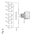
- FIG. 8 is a schematic depiction of an embodiment of a circulation loop for circulating a temperature control fluid in a temperature control circuit.
- FIG. 9 depicts two test stations, with one test station having a specimen containment module releasably attached thereto.
- FIG. 10 schematically depicts an exemplary arrangement for circulating bath fluid.
- FIG. 11 depicts an embodiment of a specimen containment module in an installed position.
- FIG. 12 is a perspective view of the orthopedic simulator of FIG. 1 , with an indication of the flexion and extension motion.
- FIG. 13 is a cross-sectional view of a portion of a flexion/extension motion linkage in accordance with embodiments of the invention.
- FIG. 14 is a perspective view of the orthopedic simulator of FIG. 1 , with an indication of the lateral bending motion around an axis of rotation.
- FIG. 15 is a rear perspective view of the orthopedic simulator of FIG. 1 .
- FIG. 16 is a perspective view of the orthopedic simulator of FIG. 1 , with an indication of anterior/posterior and lateral translation motions.
- FIG. 17 depicts a portion of an x-y slide assembly in accordance with embodiments of the present invention.
- FIG. 18 is a perspective view of the x-y slide assembly in accordance with embodiments of the present invention.
- FIG. 19 is an exploded view of the x-y slide assembly of FIG. 18 .
- FIG. 20 is a perspective view of the orthopedic simulator of FIG. 1 , with an indication of loading in a vertical direction.
- FIG. 21 is a perspective view of an embodiment of an actuator in isolation.
- FIG. 22 is a top view of the actuator of FIG. 21 .
- FIG. 23 is a side view of the actuator of FIG. 21 .
- FIG. 24 is a cross-sectional view of the actuator of FIG. 21 .
- FIG. 25 is a perspective view of the orthopedic simulator of FIG. 1 , with an indication of the axial rotation linkage and a moment provided at a test specimen.
- FIG. 26 is a rear perspective view of the orthopedic simulator of FIG. 1 , illustrating an embodiment of a central manifold in accordance with embodiments of the present invention.
- FIGS. 27-29 schematically depict different approaches to linkages.
- FIG. 30 schematically depicts a nesting order of forces in accordance with embodiments of the present invention.
- FIG. 31 shows the required forces for application to a test specimen intended for a lumbar region according to an exemplary set of curves.
- FIG. 32 shows the same information as FIG. 31 , but for cervical data.
- FIG. 33 shows curves for non-sinusoidal input data in accordance with exemplary embodiments of the invention.
- FIG. 34 depicts the orthopedic simulator within a housing.
- FIG. 35 is a rear schematic view of the orthopedic simulator and the central manifold in accordance with embodiments of the invention.
- FIG. 36 is a schematic internal view of an exemplary embodiment of the central manifold.
- FIG. 37 is a schematic of an exemplary hydraulic circuit of the orthopedic simulator.
- Embodiments of the present invention address problems relating to the routing of fluids in an orthopedic simulator, as well as vibrations during machine operation.
- the embodiments solve these problems, at least in part, by providing an integral central manifold arrangement for an orthopedic simulator.
- the manifold may be formed of a substantially solid block of material, forming a manifold housing.
- a plurality of fluid tubes can be provided in the integral central manifold.
- the fluid tubes provide fluid connectivity in a compact manner, and allows for a greater balancing of fluid and reduced plumbing.
- the integral central manifold can also serve as a structural element, and resists and transfers bending and shear forces to vertical supports, as well as provide cross-bracing in certain embodiments.
- the orthopedic simulator of the present invention may be employed, for example, as a spinal implant wear test machine. In such a configuration, the intent of ISO 18192 is satisfied.
- the orthopedic simulator is designed for accuracy as well as increased speed.
- the orthopedic simulator is a spinal implant wear test machine, but it should be apparent to those of ordinary skill in the art that this is exemplary only.
- the features, concepts and designs depicted in the following figures and description may be employed in other types of machines and orthopedic simulators.
- FIG. 1 depicts an orthopedic simulator 10 for testing of test specimens of orthopedic devices.
- the orthopedic simulator 10 has a plurality of test stations 12 .
- the orthopedic simulator 10 is able to provide forces Fx, Fy, and Fz in the x, y and z directions as depicted in FIG. 1 , shown with the x, y and z axes at one of the test stations 12 . Additionally, torques may be applied around the x, y and z axes, as depicted.
- the test specimen is not shown in FIG. 1 so as not to obscure the present invention.
- a specimen containment module is provided that contains fluids in which the test specimen is immersed.
- Upper and lower adapters 18 (only seen clearly at one of the test stations 12 in which the specimen chamber is removed for illustrative purposes) hold the test specimens between them within the specimen containment module 16 .
- a linkage 20 provides forces in the x direction with the linkage 22 providing forces in the y direction.
- Gimbals 24 are connected to the upper adapters 18 and may be moved around the y axis and around the x axis to provide moments around the x and y axes.
- Vertical loads represented by forces along the z axis, are provided by vertical load actuators 26 , as shown in FIG. 1 .
- a friction-free axial actuator is preferable to provide for a friction-free axial/torsion actuation system.
- the vertical load actuator 26 applies a vertical loading along the z axis through components 28 to the test specimen via the lower adapter 18 .
- the components 28 include an x-y slide table and a load cell.
- the vertical load actuators 26 , and the actuators driving the linkages 20 and 22 are coupled to a central manifold 92 .
- Operating fluid for the different actuators of the orthopedic simulator is routed through the central manifold 92 .
- this routing through the central manifold 92 has a number of benefits, including reducing the amount of plumbing, reducing the overall size of the simulator and achieving a greater balancing of fluid within the system.
- the integral nature of the central manifold 92 and its structure allows the central manifold 92 to resist and transfer bending and shear forces to vertical components of the machine, and be employed in a cross-bracing manner to solidify the simulator.
- An axial rotation linkage 30 is coupled to the vertical load actuator 26 .
- the motion of the axial rotation linkage 30 is around the vertical axis z, as depicted in FIG. 1 .
- the axial rotation linkage 30 is depicted at the bottom of FIG. 1 , it should be apparent to those of skill in the art that the structure depicted in FIG. 1 is suspended vertically so that the axial rotation linkages 30 are free to rotate. This will become more apparent in later-described figures.
- FIGS. 2 a - 2 d depict alternate views of the orthopedic simulator 10 .
- FIG. 2 a is a top view which best shows the arrangement of the linkages 20 with the gimbals 24 .
- a crosshead 32 is provided, which may also best be seen in FIG. 2 d .
- FIG. 2 a is a top view, while FIG. 2 b is a front view, FIG. 2 c is a bottom view and FIG. 2 d is a side view.
- FIG. 3 depicts a perspective view of the orthopedic simulator of FIG. 1 , with a specimen containment module 16 that is remote from the orthopedic simulator 10 .
- the specimen containment modules 16 are releasably attachable to the test station 12 .
- the releasable attachment feature of each of the specimen containment modules 16 enables bench top preparation work on the test specimen to be performed remotely from the environment of the orthopedic simulator 30 .
- This remote loading and preparation capability allows for careful removal and insertion of delicate test specimens. Further, the mounting of one-piece specimens is facilitated with this arrangement.
- An important consideration is the reduction in the contamination potential created by remotely mounting a specimen within the specimen containment module.
- the specimen containment module 16 also contains adapters 18 that are designed for flexibility, ease of manufacturing and low cost.
- FIG. 4 An exemplary embodiment of a specimen containment module 16 is shown in isolation in FIG. 4 , and in exploded view in FIG. 5 .
- the specimen containment module contains a base 34 and upper connector 37 that interface to a test station 12 and at which the specimen containment module 16 is releasably attached to the orthopedic simulator 10 .
- a chamber 36 when inserted into the moat 38 in the base 34 , forms a fluid container with the base 34 .
- a test specimen 40 is depicted with a lower portion 40 a and an upper portion 40 b . However, certain test specimens may also be one-piece specimens.
- Releasable fasteners 42 such as thumb screws, may be employed to releasably attach the specimen containment module 16 to the orthopedic simulator 10 .
- Fluid connections 44 are used to provide fluid as will be described in more detail in the following figures.
- FIG. 6 is a side, partially cross-sectional view of the specimen containment module 16 of FIGS. 4 and 5 .
- the test specimen 40 is shown with the upper and lower portions coupled together, as seen in FIG. 6 .
- FIG. 7 is a top view of the base 34 .
- a specimen mounting platform 46 is provided which includes two pins 48 , with one pin piloting and another pin interacting with a slot in the lower adapter 18 a for anti-rotation purposes. Screw holes 50 are depicted and may be employed to provide a specimen hold down function.
- the base 34 also includes a recess 52 that is able to interact with a pin 54 on the orthopedic simulator 10 . This provides a slidable installation of the specimen containment module 16 .
- a tubing loop 56 is provided within the base to provide a temperature control of the bath in which the test specimen 40 is immersed. As will be described in more detail, a temperature control fluid is circulated through the tubing loop 56 to precisely control the temperature of the bath.
- Recesses 58 provide for thumb screws or other releasable fasteners to secure the specimen containment module 16 to the orthopedic simulator 10 .
- a temperature probe 60 provides feedback on the temperature of the bath and can be used to control the temperature control fluid.
- Bath fluid circulation tubes 62 are used to circulate bath fluid within the fluid container formed by the base 34 and the chamber 36 .
- FIG. 8 depicts a circulation loop for circulating the temperature control fluid in the temperature control circuit.
- the temperature control fluid is circulated in each of the specimen containment modules through the tubing loops 56 , as seen in FIG. 7 .
- a single circulation loop 64 circulates a temperature control fluid, such as water, through the closed loop system.
- the tempered water is circulated through the heat exchangers in each of the baths of the specimen containment modules.
- the heater 66 provides a precise control and circulation of the tempered water. This daisy-chained approach produces a very stable temperature in each of the baths at the specimen containment modules 16 .
- each of the baths may be individually controlled with separate circulation loops for each bath.
- the embodiment depicted in FIG. 8 is preferred. This arrangement also has the advantage over electric heating elements or other types of heating, in preventing overtemperature related fluid degradation.
- FIG. 9 depicts two test stations 12 , one of which has a specimen containment module 16 releasably attached thereto.
- a non-contact level sensor 68 such as those known in the sensing art, are provided on posts 70 near the chamber 36 . The height of the non-contact level sensor 68 may be adjusted along the pillar 70 in the direction of arrow 72 . This allows the desired fluid height within the chamber 36 to be precisely adjusted.
- the non-contact level sensor 68 provides its signals to a fill controller 74 , schematically indicated as being connected to a non-contact level sensor 68 .
- the fill control 74 based upon the signals received from the non-contact level sensors 68 , determines whether the fluid in the specimen containment module 16 needs to be replenished.
- the test fluid such as bovine fluid, for example, may evaporate to some extent, thereby increasing the concentration of the fluid. Distilled water is furnished (through a fill tube, not shown) under the control of the fill control 74 .
- FIG. 10 An arrangement for the circulation of the bath fluid is depicted in FIG. 10 .
- individual loops are preferred in order to maintain each test specimen and bath in its own environment. In other words, cross-contamination of wear particles is avoided by providing the individual loops for each specimen module.
- peristaltic pumps 76 are employed for each of the individual loops. A stirring action is provided.
- FIG. 11 shows a specimen containment module 16 (without the chamber 36 for illustrative purposes) in an installed position within the orthopedic simulator 10 .
- the specimen containment module is releasably attached at its base 34 to a load cell module 78 .
- the load cell module is designed to accommodate either a single or multi-axis force transducer. In the illustrated embodiment, a single axis transducer is depicted.
- FIG. 12 depicts the orthopedic simulator 10 and exemplifies the flexion/extension motion.
- the linear actuator 20 a of the linkage 20 extends back and forth in an axial manner, causing the connecting link 20 b to translate in an axial direction. This causes the inner gimbals 24 at the test stations 12 to move and rotate around an axis of rotation depicted in FIG. 12 .
- connecting link 20 b and connections to the inner gimbals 24 employ high quality bearings, such as long life needle bearings used at key points.
- high quality bearings such as long life needle bearings used at key points.
- the design insures a long life and low lash, creating an accurate machine for a long term use.
- the low moving mass linkage depicted maximizes performance and is designed for ease of maintenance.
- FIG. 13 depicts a cross-sectional portion of the flexion/extension motion linkage.
- the inner gimbal 24 is depicted as being connected to the upper specimen adapter 18 b .
- a stationary bearing housing 80 houses the needle bearings mentioned before.
- a radial needle bearing 84 is provided, as well as a needle roller thrust bearing 82 , which are provided in two places.
- a tubular shaft 86 permits rotation of the gimbals 24 .
- FIG. 14 A lateral bending motion around the axis of rotation is depicted in FIG. 14 .
- a moving cross-head 32 (also seen in FIGS. 2 a - 2 d ) is coupled via a connecting link 88 that is moved by linear actuator 90 in an up-and-down motion. This causes the inner gimbals 24 to be pivoted around the axis of rotation.
- FIG. 15 A rear view of the orthopedic simulator 10 is provided in FIG. 15 .
- the moving cross-head 32 is shown as extending across the orthopedic simulator 10 .
- a central manifold 92 which will be discussed in more detail later.
- long life needle bearings that are of high quality at the key points in the lateral bending motion linkages. These designs ensure long life and low lash, creating an accurate machine for long term use.
- the low moving mass crosshead assembly maximizes performance.
- the crosshead assembly 32 may be made of aluminum to provide a very light weight moving mass. In motion, the moving crosshead 32 pivots around the x-axis depicted in FIG. 15 .
- FIG. 16 shows the orthopedic simulator and depicts the anterior/posterior and lateral translation motions.
- a translation stage 96 is illustrated in this drawing.
- the translation stage includes an x-y slide assembly as will be see in the following figures.
- FIG. 17 depicts a portion of the x-y slide assembly 100 that shows linear slides 102 with a space 104 being provided for springs that produce a biasing force if desired.
- FIG. 18 is a perspective view of the x-y slide table 100 constructed in accordance with embodiments of the present invention.
- FIG. 19 shows the x-y slide table 100 in an exploded view.
- the x-y slide assembly 100 forms a very compact package, with a very light weight assembly.
- Each slide assembly 100 also has high moment load ratings, due to its efficient design.
- the x-y slide assembly 100 of the present invention may incorporate three different modes of operation. These include free-floating to self-center a specimen; a positive axis lock within dynamic range; and an ability to produce a high amount of static shear force, on each axis, for simultaneous shear plane loading of specimens.
- the x-axis transition plate has a built-in capability to align the upper specimen tooling and the load cell radially.
- the x-y slide assembly 100 of the present invention overcomes particular concerns. For example, other such assemblies in orthopedic simulators used ball bearings in the slide design which lend themselves to fretting and skidding when translating. Other advantages of the present invention include the production of simultaneous transverse shear in a compact design, while producing friction-free stage floating, but yet is infinitely lockable within a dynamic range. The lowest inertia assembly for Mz rotation is produced, at all six test stations 12 . The design of the x-y slide assembly 100 can withstand 1000 plus lbsF in compression. Further, the x-y slide assembly 100 is a translation assembly that can be easily removed from the Fz actuator 26 . It also provides a translation assembly that has over-turning moment capability to react moments caused by side loads that are off-centered loading.
- the x-y slide assembly 100 includes a lower translation plate 100 and an upper translation plate 112 .
- the lower translation plate 110 translates along the x-axis while the upper translation plate 112 translates along the y axis.
- a base 114 supports the x-y slide assembly and may be mounted on the load cell depicted earlier.
- Pins 116 are provided and pressed into base 114 and lower translation plate 110 .
- the pins 116 aid in assembly of thee the first mounted slide/rail at each axis and ensures squareness of the first rail to the lock screw post, and establish orthogonality between axis platforms, within the limits of the small screw clearances.
- Screws 118 are provided, as well as pin dowels 120 .
- Linear rail bearings 122 are provided for linear rails 124 .
- FIG. 20 depicts the orthopedic simulator 10 and illustrates the loading in the z direction that is provided in the direction of arrows 128 by the vertical load actuator 26 .
- the integral actuator 26 is integral in nature and may be a precision, seal-less actuator design in certain preferred embodiments.
- the piston rod is floated on an oil film, and the near zero friction maximizes the load accuracy.
- a low mass rod may be employed to maximize the performance of axial rotation and vertical load channels.
- the individual test stations 12 have their own on-off valves.
- a perspective view of an actuator 26 in isolation is provided in FIG. 21 .
- a top view of the actuator 26 is depicted in FIG. 22 and a side view of the actuator 26 is depicted in FIG. 23 .
- a cross-sectional view of the actuator 26 is depicted in FIG. 24 .
- each actuator 26 has a handle 130 on the outside of the actuator 26 that operates a built-in hydraulic valve that allows a user to shut off any station individually.
- the actuator 26 includes a piston 132 that may be moved axially and rotated.
- the hydraulic actuator 26 includes a bottom end cap 134 and a top end cap 136 .
- the hydrostatic bearings 138 and 140 are provided. Thrust bearings 142 provide support for a test station 12 when the device is shut off. In such a case, a test station can be removed and the machine operated without the non-operation test station 12 influencing the other test stations 12 .
- Pressure to extend the piston 132 along the z-axis is provided at port 144 , while pressure to retract the piston 132 is provided at port 146 .
- the hydraulic pressure in return ports 144 , 146 are connected to and fed from the central manifold 92 in preferred embodiments.
- the hydraulic actuator 26 is hydrostatic and is completely without seals, including high-pressure piston seals.
- the hydrostatic bearings “float” the piston rod and also provide some over-turning moment capabilities.
- the unique design produces an actuator without seal drag (as in a typical hydraulic actuator), resulting in a device that has extremely low linear and torsional friction. The only friction is the friction that is produced from viscous oil shear. With this design, an equal Fz force is provided across all seven actuators.
- Thrust bearings are provided in the end of each end cap 134 , 136 .
- the upper end cap 136 has thrust bearings lubricated by a blow-by actuator rod oil leakage. If one specimen should fail before others, an operator can turn off the station 12 .
- the actuator 26 retracts and the assembly will ride on the thrust bearings for a continued Mz motion.
- the Mz motion is common for all six Fz actuators 26 at the six test stations 12 .
- the seventh test station 14 which operates as a load and soak station for control purposes, is not connected to the Mz drive apparatus.
- the central manifold 92 provides an integral manifold for multiple connections and fluid tubing for the orthopedic simulator.
- the use of a central integral manifold greatly reduces plumbing, provides a performance improvement since there is a greater balancing of fluid and less plumbing is required, a size reduction, a cost reduction and also serves as a structural element.
- the central manifold 92 provides a strong cross-brace for the orthopedic simulator 10 .
- Examples of the plumbing include providing the fluid to the extension and retraction fluid connections of the vertical load actuators 26 .
- the central manifold 92 also provides for lubrication fluid circulation.
- FIG. 35 A schematic depiction of the central manifold 92 installed as a structural element is provided in FIG. 35 .
- the manifold 92 spans the test stations 12 and is structurally coupled to, for example, a pair of vertical supports 205 .
- the central manifold 92 coupled in this manner, can thereby serve as a cross-brace for the orthopedic simulator 10 . This will reduce the effect of vibrations during the testing operation.
- the vertical supports 205 are exemplary support elements only, as the central manifold 92 may be structurally coupled to other structural and support elements of the orthopedic simulator 10 , such as the walls of the external housing for the orthopedic simulator 10 Further, presently preferred embodiments of the invention employ three vertical supports 205 to which the central manifold 92 is coupled. Also schematically depicted in FIG. 35 is a sump system 202 into which operating fluid is collected, and which will be discussed later.
- FIG. 36 A basic cross-sectional depiction of an embodiment of the central manifold 92 is provided in FIG. 36 .
- This embodiment is exemplary only, as other internal connections and tubing arrangements are provided in different embodiments, depending on the particular configuration of the orthopedic simulator 10 . Certain details are not illustrated so as not to obscure some of the inventive aspects. For example, a number of valves and connections may be provided, but are not illustrated.
- FIG. 37 is a schematic diagram of a hydraulic system for the orthopedic simulator 10 . Again, this is an exemplary embodiment only, as other configurations of the hydraulic system may be employed depending on the particular arrangement and needs of the orthopedic simulator 10 . Furthermore, the configuration of the orthopedic simulator 10 to operate with a hydraulic system and the configuration of the central manifold 92 to accommodate the hydraulic connections is exemplary only. In certain other embodiments, the orthopedic simulator 10 operates on pneumatics, and in other embodiments, is an electric system. The central manifold 92 , in such embodiments, is configured to accommodate the pneumatic or electrical connections.
- the central manifold 92 can serve as an integral heat sink and structure and also serve as a portion of an actuator itself.
- Surface mount components can be mounted directly to the central manifold 92 .
- the central manifold 92 comprises a manifold housing 208 that is formed from a substantially solid block of material.
- the manifold housing 208 may be formed from a solid block of aluminum or other appropriate metal.
- different materials may be used, though it is preferred to provide the structural reinforcement capability discussed earlier for the material to have a high rigidity.
- the manifold housing 208 is not formed from a substantially solid block of material, but rather is hollow and formed by a number of walls enclosing a space. The reinforcing capability may be compromised to some extent by being a hollow housing, but in certain applications, the amount of reinforcement provided by such a structure may be sufficient.
- a number of fluid tubes are provided in the manifold housing 208 .
- the tubes and connections between the tubes may be created by appropriate drilling or other methods.
- a switched pressure tube 210 carries pressurized hydraulic fluid for distribution to the various actuators.
- the switched pressure tube 210 provides the hydraulic fluid to operate Mz actuator 232 through a servo valve 230 .
- An example of an Mz actuator 232 is the linear actuator 150 in FIG. 26 , although types of Mz actuators may be employed.
- the Mx actuator 236 is provided with hydraulic fluid through servo valve 234
- My actuator 240 is provided with hydraulic fluid through servo valve 238 .
- a second switched pressure tube 218 is formed within the manifold housing 208 and contains fluid inlets 224 .
- the second switched pressure tube 218 is coupled to the switched pressure tube 210 and provides additional pressure points.
- a return collector tube 216 is provided that is connected by fluid inlets 224 to the servo valves 230 , 234 , 238 . It is also connected to ganged servo valve 226 , which will be discussed in more detail below.
- the return collector tube 216 receives return hydraulic fluid from the servo valves 226 , 230 , 234 and 238 . The hydraulic fluid is returned to the sump system 202 .
- An on/off valve 252 connects a source of pressurization to the switched pressure tube 210 .
- a dump valve 254 allows fluid to be provided from the switched pressure tube 210 to the return collector tube 216 .
- a time delay based on the operation of the on/off valve 252 may be utilized to control the dump valve 254 .
- An accumulator 220 is coupled to the switched pressure tube 210 , and another accumulator 222 is coupled to the return collector tube 216 .
- the accumulators 220 , 222 store hydraulic energy and make this energy available again to the system as necessary.
- the switched pressure tube 210 provides hydraulic pressure to a first operating pressure tube 212 and a second operating pressure tube 214 .
- the hydraulic pressure is provided through the ganged servo valve 226 , under the control of the pressure control valve 248 .
- the plurality of Fz actuators 26 are have extension and retraction ports coupled respectively to the first operating pressure tube 212 and the second operating pressure tube 214 through the fluid outlets 222 (shown in FIG. 35 ). Hence, operation of the Fz actuators 26 is controlled by pressurization provided through the first and second operating pressure tubes 212 , 214 . Hydraulic fluid is allowed to drain into the sump system 202 from the Fz actuators 26 .
- the first and second operating pressure tubes 212 and 214 have relatively wide diameters, in certain embodiments, to provide low loss. It is desired to make the plurality of Fz actuators 26 self-balanced, such that they experience the same pressure. To achieve this, in certain embodiments, all the chains from the servo valve 226 to each of the Fz actuators 26 are made as common as possible. The servo valve 226 is physically located in the middle of the Fz actuators 26 , in order to compensate to the greatest extent for different distances from the inlet of the pressurized fluid.
- the routing of all of the hydraulic connections in the central manifold provides an improved balancing of the hydraulic fluid in the system. As well, reductions in size and cost are achieved.
- the central manifold 92 When attached to other structural elements of the orthopedic simulator 10 , the central manifold 92 provides a reinforcing function, so as to resist and transfer bending and shear forces to the vertical supports. This is beneficial in solidifying the simulator 10 , helping to quiet vibrations and improve testing consistency and accuracy.
- the central manifold 92 can also be configured, as discussed earlier, to provide routing for pneumatic or electrical connections in certain embodiments, or some combination of hydraulic, pneumatic and electrical connections.
- the central manifold 92 can be considered to contain operating power transmission carriers of different types, such as hydraulic fluid tubing, pneumatic tubing, or electrical wiring, depending on the type of actuators that are employed. Whichever connections are provided, the central manifold 92 achieves the structural purpose of resisting and transferring bending and shear forces in addition to making the machine more compact.
- FIG. 25 shows the orthopedic simulator 10 and highlights the axial rotation linkage 30 originally shown in FIG. 1 .
- the axial rotation linkage 30 provides a moment Mz at the test specimen.
- FIG. 26 which shows a rear view of the orthopedic simulator 10 , a linear actuator 150 , via connecting link 152 , provides the driving force that causes the axial rotation linkages 30 to rotate around the z-axis.
- the axial rotation linkage includes a rotational transfer link 154 that is coupled to the connecting link 152 . Movement of the connecting link 152 in a linear fashion causes the rotational transfer link 154 to freely rotate on bearings around the z-axis.
- a flexure assembly 156 that is torsionally stiff but axially compliant is coupled to the bottom of the piston 132 of the vertical load actuator 26 .
- the flexure assembly is torsionally stiff so as to rigidly transfer torque between the rotational transfer link 154 and the piston 132 of the actuator 26 .
- a friction free axial/torsion actuation is provided by the combination of the actual rotation linkage 30 and the friction-free vertical force actuator 26 .
- the vertical load actuator 26 applies a load to the test specimen 40 along the z-axis by moving the piston 132 along the z-axis.
- the rotational transfer link 154 and the flexure assembly 156 facilitate rigid torque transfer to the piston 132 to the test specimen (not shown) at one of the test stations 12 .
- the piston 132 is allowed to translate along its axis freely due to the high axial compliance provided by the flexure assembly 56 of the axial rotation linkage 30 .
- FIGS. 27-29 depict linkage approaches and highlight the differences between embodiments of the present invention and alternate linkage approaches which provide greater joint serialization error.
- a common sublinkage is provided for the flexion/extension (My) and axial rotation (Mz) to thereby create the fewest common number of joints between each specimen, between the displacement measuring device and each specimen, and between the drive actuator and each specimen. In this manner, variability is minimized.
- the approach provided in the present invention is depicted in FIG. 27 .
- the solid cross-piece 160 provides force to all the linkages 162 at once, from the actuation mechanism 164 .
- FIG. 28 employs three separate connecting bars 166 which are connected by two links 168 .
- those test specimens at the left side of FIG. 28 have a larger number of joints ( 8 ) than the number of joints ( 4 ) for the left-most specimen in FIG. 27 .
- This increases the variability in the forces and motions applied to the test specimens from test station to test station.
- a similar variability is provided in FIG. 29 , in which a large number of joints are provided for the various test stations, with each test station having a different number of joints.
- the arrangement of the present invention reduces variability in force and motion application from test station to test station.
- FIG. 30 schematically depicts the nesting order of forces in accordance with embodiments of the present invention. This nesting order of forces is achieved by the arrangement of the linkages as depicted in the figures throughout this application.
- the mechanism system generates relative motions and forces between the lower (inferior) and upper (superior) portions of orthopedic devices, such as multiple intervertable disc implants, simultaneously to generate wear on the artificial bearing surfaces over similar motion and force induced degradation with time.
- the mechanism applies these motions and forces in such a way as to maximize the accuracy, test speed and durability of the linkage.
- the full six degree of freedom linkage system is nested as shown in FIG. 30 to maximize performance and accuracy.
- Typical spinal implant tests in conventional systems require higher displacements in the flexion/extension direction (My), as compared to the lateral bending (Mx) and axial rotation (Mz) rotations. These motions are often performed at a common or similar frequency and wave shapes. Therefore, the flexion/extension motion represents the most demanding performance.
- the mechanism system of the present invention is nested, however, so as to place the sub-mechanism with the highest required performance closest to the specimen. This thereby minimizes the moving mass and any related inertial induced error.
- the schematically induced specimen is indicated by reference numeral 170 .
- the closest sub-mechanism to the superior (upper) portion of the test specimen 170 is the flexion/extension (My).
- the lateral bending (Mx) is further from the superior portion of the specimen 170 , as indicated by FIG. 30 .
- the drive for the Mx and My forces is furthest away from the specimen 170 .
- the force in the y direction is free, fixed or biased and has a minimized moving mass and has the highest required performance.
- the forces in the x direction Fx is then nested further from the specimen 170 than the Fy force.
- the vertical force provided by the actuator 26 , Fz is still further from the inferior portion of the test specimen 170 , with the moment around the z-axis, Mz, being provided in a nesting arrangement still further from the test specimen 170 .
- the drive for all these forces is provided as indicated.
- the Euler sequence of rotational motion as applied by the mechanism of the present invention is flexion/extension->lateral bending->axial rotation.
- this ordering of the mechanism promotes maximum performance and minimizes the additive joint error.
- the independency of linkages reduces or eliminates cross-talk and allows accurate control of the phases between the individual mechanisms. This is important to create the desired and controlled loading of the test specimen 170 .
- FIG. 31 shows the required forces for applying to a test specimen of a spinal implant intended for the lumbar region according to the an exemplary set of curves.
- FIG. 32 shows the same information for cervical data.
- Duty cycle loading involves inserting high loads and displacement activity into a more typical repeating activity, such as lifting a heavy box periodically. This allows for the insertion of periodic overload states. Such overload states are known to potentially induce damage, but are relatively rare so that their rarity should be considered and the overload states placed in the context of other daily activity when included.
- embodiments of the present invention provide for re-creating any sinusoidal or non-sinusoidal curve, which allows for more accurate simulation (e.g., a “walking simulation”).
- the embodiments of the invention allow for inputting non-sinusoidal data with varying phase, amplitude and frequency content, such as real walking profiles. These curves, such as shown in FIG. 33 , can be repeated for a large number of cycles, and hence are fatigue or wear generating.
- the representation of activity is not limited to walking, as one of ordinary skill in the art will readily appreciate, but may be used to simulate any number of replicated activities in a serial or repetitive fashion.
- a controller 200 seen only in FIG. 1 , is used to independently and individually control each of the motion devices. Hence, the flexion/extension, lateral bending, rotation, and loading of the test specimen 170 may be controlled to any desirable curve through the use of control software and the mechanisms provided in the orthopedic simulator 10 .
- a test may account for the typical day for humans. Such a day may include sitting for hours at a time with intermittent periods of activity, including walking and sleeping periods. Strenuous physical activity, such as for athletes, may also be better modeled. The controller 200 thereby more accurately causes the orthopedic simulator 10 to simulate the forces that a spinal implant or other orthopedic device will actually be expected to see for a typical implant recipient.
- FIG. 34 depicts the orthopedic simulator 10 within a housing 178 .
- the use of a housing 178 prevents contamination and reduces oil within the environment.
- Switches 180 allow a test station to be shut down very quickly in order to prevent invalidating of a test if an individual test station 12 should experience difficulty in operation.
Abstract
Description
Claims (20)
Priority Applications (3)
| Application Number | Priority Date | Filing Date | Title |
|---|---|---|---|
| US11/649,961 US7824184B2 (en) | 2006-01-13 | 2007-01-05 | Integrated central manifold for orthopedic simulator |
| EP07716565.2A EP1977213B1 (en) | 2006-01-13 | 2007-01-10 | Integrated central manifold for orthopedic simulator |
| PCT/US2007/000797 WO2007084355A2 (en) | 2006-01-13 | 2007-01-10 | Integrated central manifold for orthopedic simulator |
Applications Claiming Priority (4)
| Application Number | Priority Date | Filing Date | Title |
|---|---|---|---|
| US11/332,407 US7617744B2 (en) | 2006-01-13 | 2006-01-13 | Transmission for torque transfer with axial compliance |
| US76059506P | 2006-01-20 | 2006-01-20 | |
| US11/335,974 US7654150B2 (en) | 2006-01-20 | 2006-01-20 | Specimen containment module for orthopedic simulator |
| US11/649,961 US7824184B2 (en) | 2006-01-13 | 2007-01-05 | Integrated central manifold for orthopedic simulator |
Related Parent Applications (1)
| Application Number | Title | Priority Date | Filing Date |
|---|---|---|---|
| US11/332,407 Continuation-In-Part US7617744B2 (en) | 2006-01-13 | 2006-01-13 | Transmission for torque transfer with axial compliance |
Publications (2)
| Publication Number | Publication Date |
|---|---|
| US20070169566A1 US20070169566A1 (en) | 2007-07-26 |
| US7824184B2 true US7824184B2 (en) | 2010-11-02 |
Family
ID=38288123
Family Applications (1)
| Application Number | Title | Priority Date | Filing Date |
|---|---|---|---|
| US11/649,961 Active 2028-05-10 US7824184B2 (en) | 2006-01-13 | 2007-01-05 | Integrated central manifold for orthopedic simulator |
Country Status (3)
| Country | Link |
|---|---|
| US (1) | US7824184B2 (en) |
| EP (1) | EP1977213B1 (en) |
| WO (1) | WO2007084355A2 (en) |
Cited By (1)
| Publication number | Priority date | Publication date | Assignee | Title |
|---|---|---|---|---|
| RU2662599C2 (en) * | 2016-01-12 | 2018-07-26 | Федеральное государственное автономное образовательное учреждение высшего образования "Севастопольский государственный университет" | Simulator for wear testing of hip endoprostheses |
Families Citing this family (6)
| Publication number | Priority date | Publication date | Assignee | Title |
|---|---|---|---|---|
| US7762147B2 (en) * | 2006-01-13 | 2010-07-27 | Mts Systems Corporation | Orthopedic simulator with integral load actuators |
| US7770446B2 (en) * | 2006-01-13 | 2010-08-10 | Mts Systems Corporation | Orthopedic simulator with temperature controller arrangement for controlling temperature of specimen baths |
| US7913573B2 (en) * | 2006-01-13 | 2011-03-29 | Mts Systems Corporation | Orthopedic simulator with a multi-axis slide table assembly |
| US7779708B2 (en) * | 2006-01-13 | 2010-08-24 | Mts Systems Corporation | Orthopedic simulator with fluid concentration maintenance arrangement for controlling fluid concentration of specimen baths |
| US20070169567A1 (en) * | 2006-01-20 | 2007-07-26 | Mts Systems Corporation | Duty cycle loading for orthopedic simulator |
| EP2623953A1 (en) * | 2012-02-03 | 2013-08-07 | Thelkin Ag | Test container |
Citations (71)
| Publication number | Priority date | Publication date | Assignee | Title |
|---|---|---|---|---|
| US170361A (en) | 1875-11-23 | Improvement in shifting carriage-tops | ||
| GB1108652A (en) * | 1965-07-12 | 1968-04-03 | Westinghouse Electric Corp | Human circulatory system simulator |
| US3597967A (en) | 1968-02-26 | 1971-08-10 | Ceskoslovenska Akademie Ved | Apparatus for applying random mechanical loads to a test specimen |
| US3658143A (en) | 1970-11-20 | 1972-04-25 | Nat Controls | Flexure plate scale with hydraulic load cell |
| US3937071A (en) | 1975-07-11 | 1976-02-10 | The United States Of America As Represented By The Secretary Of The Army | Fatigue test apparatus |
| DE2728007B1 (en) | 1977-06-22 | 1978-08-03 | Michael Dr Ungethuem | Simulator for testing total endoprostheses for the hip joint |
| US4196635A (en) | 1977-12-23 | 1980-04-08 | Carl Schenck Ag | Test apparatus for the simultaneous loading of a test sample with longitudinal forces and with torque |
| US4318301A (en) | 1980-06-23 | 1982-03-09 | President And Fellows Of Harvard College | Apparatus for measuring papillary muscle contractility |
| US4428238A (en) | 1981-10-05 | 1984-01-31 | Team Corporation | Vibrating test screening apparatus |
| US4676110A (en) | 1986-07-16 | 1987-06-30 | The United States Of America As Represented By The Administrator Of The National Aeronautics And Space Administration | Fatigue testing a plurality of test specimens and method |
| US4882677A (en) | 1987-09-03 | 1989-11-21 | Curran Thomas M | Isometric strength testing method and equipment for disability evaluation |
| US5009523A (en) | 1989-07-20 | 1991-04-23 | The Timken Company | Double row bearing assembly |
| US5014719A (en) | 1984-02-02 | 1991-05-14 | Mcleod Paul C | Knee loading and testing apparatus and method |
| US5151859A (en) | 1989-06-29 | 1992-09-29 | Honda Giken Kogyo Kabushiki Kaisha | Legged walking robot and system for controlling the same |
| US5259249A (en) | 1991-04-22 | 1993-11-09 | New York University | Hip joint femoral component endoprosthesis test device |
| US5324247A (en) | 1991-11-26 | 1994-06-28 | Alaska Research And Development, Inc. | Apparatus and method for multi-axial spinal testing and rehabilitation |
| US5327038A (en) | 1991-05-09 | 1994-07-05 | Rockwell International Corporation | Walking expansion actuator |
| US5337758A (en) | 1991-01-11 | 1994-08-16 | Orthopedic Systems, Inc. | Spine motion analyzer and method |
| US5360016A (en) | 1991-04-05 | 1994-11-01 | N. K. Biotechnical Engineering Company | Force transducer for a joint prosthesis |
| US5403252A (en) | 1992-05-12 | 1995-04-04 | Life Fitness | Exercise apparatus and method for simulating hill climbing |
| US5415661A (en) | 1993-03-24 | 1995-05-16 | University Of Miami | Implantable spinal assist device |
| DE4411508A1 (en) | 1994-04-02 | 1995-10-05 | Cerasiv Gmbh | Ceramic hip joint ball test appts. |
| US5511431A (en) | 1993-09-24 | 1996-04-30 | Instron Limited | Structure testing machine |
| US5569858A (en) | 1994-05-16 | 1996-10-29 | The B. F. Goodrich Company | Viscoelastic material testing system |
| US5670708A (en) * | 1996-04-02 | 1997-09-23 | Endura-Tec Systems Corporation | High frequency intravascular prosthesis fatigue tester |
| US5869328A (en) | 1997-08-08 | 1999-02-09 | Cdc Technologies, Inc. | Cuvette for performing a diagnostic test on a specimen |
| EP0919201A1 (en) | 1997-11-26 | 1999-06-02 | Howmedica Inc. | Kinematic restraint device and method for determining the range of motion of a total knee replacement system |
| US5936858A (en) | 1996-06-27 | 1999-08-10 | Toyota Jidosha Kabushiki Kaisha | Actuator controller for state feedback control |
| US5952582A (en) | 1996-12-27 | 1999-09-14 | Shimadzu Corporation | Test apparatus with control constant computing device |
| US5959215A (en) | 1995-04-12 | 1999-09-28 | Bridgestone Corporation | Heat build-up/fatigue measuring method for viscoelastic body and hydraulic servo flexometer |
| US5999168A (en) | 1995-09-27 | 1999-12-07 | Immersion Corporation | Haptic accelerator for force feedback computer peripherals |
| US6058784A (en) | 1998-02-03 | 2000-05-09 | Mts Systems Corporation | Material testing apparatus having separated load generating mechanisms |
| US6171812B1 (en) | 1997-07-15 | 2001-01-09 | The National Institute Of Biogerontology, Inc. | Combined perfusion and mechanical loading system for explanted bone |
| US6230574B1 (en) * | 1998-10-09 | 2001-05-15 | Risk Analysis & Management | Apparatus and method for measuring strangulation effect |
| US20020029610A1 (en) | 2000-05-12 | 2002-03-14 | Chrystall Keith G. | Motion platform and method of use |
| US6418392B1 (en) | 1998-03-20 | 2002-07-09 | National Instruments Corporation | System and method for simulating operations of an instrument |
| US6447448B1 (en) | 1998-12-31 | 2002-09-10 | Ball Semiconductor, Inc. | Miniature implanted orthopedic sensors |
| US6447518B1 (en) | 1995-07-18 | 2002-09-10 | William R. Krause | Flexible shaft components |
| US6472202B1 (en) | 1998-05-08 | 2002-10-29 | Flexcell International Corporation | Loading station assembly and method for tissue engineering |
| US20020166387A1 (en) | 2001-05-09 | 2002-11-14 | Grote Vogel P. | Test specimen holder |
| US6502837B1 (en) | 1998-11-11 | 2003-01-07 | Kenmar Company Trust | Enhanced computer optimized adaptive suspension system and method |
| US6510740B1 (en) | 1999-09-28 | 2003-01-28 | Rosemount Inc. | Thermal management in a pressure transmitter |
| US20030029247A1 (en) | 2001-08-10 | 2003-02-13 | Biedermann Motech Gmbh | Sensor device, in particular for a prosthesis, and prosthesis having such a sensor device |
| US20030053901A1 (en) | 1999-08-05 | 2003-03-20 | Roy Shambhu Nath | Parallel kinematics mechanism with a concentric spherical joint |
| US6538215B2 (en) | 2000-01-13 | 2003-03-25 | Sunbeam Products, Inc. | Programmable digital scale |
| US6571373B1 (en) | 2000-01-31 | 2003-05-27 | International Business Machines Corporation | Simulator-independent system-on-chip verification methodology |
| US20030110830A1 (en) * | 2001-07-23 | 2003-06-19 | Mark Dehdashtian | Methods and apparatuses for measuring the compliance of stents and stented grafts |
| US6645251B2 (en) | 2001-01-22 | 2003-11-11 | Smith & Nephew, Inc. | Surfaces and processes for wear reducing in orthopaedic implants |
| US6659200B1 (en) | 1999-12-20 | 2003-12-09 | Halliburton Energy Services, Inc. | Actuator assembly and method for actuating downhole assembly |
| US20040019382A1 (en) | 2002-03-19 | 2004-01-29 | Farid Amirouche | System and method for prosthetic fitting and balancing in joints |
| US20040019384A1 (en) | 2002-07-24 | 2004-01-29 | Bryan Kirking | Implantable prosthesis for measuring six force components |
| US6706005B2 (en) | 2000-08-25 | 2004-03-16 | The Cleveland Clinic Foundation | Apparatus and method for assessing loads on adjacent bones |
| US6715336B1 (en) | 2003-02-24 | 2004-04-06 | Npoint, Inc. | Piezoelectric force motion scanner |
| US6721922B1 (en) | 2000-09-27 | 2004-04-13 | Cadence Design Systems, Inc. | System for electronic circuit characterization, analysis, modeling and plan development |
| US6860156B1 (en) | 2004-05-24 | 2005-03-01 | The United States Of America As Represented By The Secretary Of The Navy | Combined in-plane shear and multi-axial tension or compression testing apparatus |
| US6865954B2 (en) | 2003-03-10 | 2005-03-15 | Spinecore, Inc. | Joint simulator testing machine |
| US20050241404A1 (en) | 2004-05-03 | 2005-11-03 | Salvesen William R | Method and apparatus for testing a joint replacement device |
| US7029475B2 (en) | 2003-05-02 | 2006-04-18 | Yale University | Spinal stabilization method |
| US7204160B1 (en) | 2004-05-24 | 2007-04-17 | The United States Of America As Represented By The Secretary Of The Navy | Biaxial and shear testing apparatus with force controls |
| US20070169561A1 (en) | 2006-01-13 | 2007-07-26 | Mts Systems Corporation | Mechanism arrangement for orthopedic simulator |
| US20070169565A1 (en) | 2006-01-13 | 2007-07-26 | Mts Systems Corporation | Orthopedic simulator with temperature controller arrangement for controlling temperature of specimen baths |
| US20070169567A1 (en) | 2006-01-20 | 2007-07-26 | Mts Systems Corporation | Duty cycle loading for orthopedic simulator |
| US20070169573A1 (en) | 2006-01-13 | 2007-07-26 | Mts Systems Corporation | Orthopedic simulator with fluid concentration maintenance arrangement for controlling fluid concentration of specimen baths |
| US20070169572A1 (en) | 2006-01-13 | 2007-07-26 | Mts Systems Corporation | Orthopedic simulator with a multi-axis slide table assembly |
| US7333111B2 (en) | 2003-04-25 | 2008-02-19 | Honda Giken Kogyo Kabushiki Kaisha | Joint component framework for modeling complex joint behavior |
| US7383738B2 (en) | 2003-12-05 | 2008-06-10 | Mts Systems Corporation | Method to extend testing through integration of measured responses virtual models |
| US7403883B2 (en) * | 2003-10-03 | 2008-07-22 | Medtronic, Inc. | Three-dimensional in-vitro spinal models and methods of analyzing substance distribution therein |
| US7427199B2 (en) * | 2005-02-03 | 2008-09-23 | Christopher Sakezles | Models and methods of using same for testing medical devices |
| US7617744B2 (en) | 2006-01-13 | 2009-11-17 | Mts Systems Corporation | Transmission for torque transfer with axial compliance |
| US7632100B2 (en) * | 2004-09-03 | 2009-12-15 | Birth Injury Prevention, Llc | Brachial plexus simulator |
| US7654150B2 (en) | 2006-01-20 | 2010-02-02 | Mts Systems Corporation | Specimen containment module for orthopedic simulator |
Family Cites Families (5)
| Publication number | Priority date | Publication date | Assignee | Title |
|---|---|---|---|---|
| AU6265696A (en) * | 1995-06-07 | 1996-12-30 | St. Jude Medical Inc. | Cardiovascular bioreactor apparatus and method |
| US6598486B2 (en) * | 2001-05-21 | 2003-07-29 | Enduratec Systems Corporation | Portable device for testing the shear response of a material in response to a repetitive applied force |
| US7348175B2 (en) | 2002-03-15 | 2008-03-25 | St3 Development Corporation | Bioreactor with plurality of chambers for conditioning intravascular tissue engineered medical products |
| US20040219659A1 (en) | 2002-04-22 | 2004-11-04 | Altman Gregory H. | Multi-dimensional strain bioreactor |
| US6810751B2 (en) * | 2002-07-29 | 2004-11-02 | Michael R. Moreno | Method and apparatus for vascular durability and fatigue testing |
-
2007
- 2007-01-05 US US11/649,961 patent/US7824184B2/en active Active
- 2007-01-10 WO PCT/US2007/000797 patent/WO2007084355A2/en active Application Filing
- 2007-01-10 EP EP07716565.2A patent/EP1977213B1/en active Active
Patent Citations (81)
| Publication number | Priority date | Publication date | Assignee | Title |
|---|---|---|---|---|
| US170361A (en) | 1875-11-23 | Improvement in shifting carriage-tops | ||
| GB1108652A (en) * | 1965-07-12 | 1968-04-03 | Westinghouse Electric Corp | Human circulatory system simulator |
| US3597967A (en) | 1968-02-26 | 1971-08-10 | Ceskoslovenska Akademie Ved | Apparatus for applying random mechanical loads to a test specimen |
| US3658143A (en) | 1970-11-20 | 1972-04-25 | Nat Controls | Flexure plate scale with hydraulic load cell |
| US3937071A (en) | 1975-07-11 | 1976-02-10 | The United States Of America As Represented By The Secretary Of The Army | Fatigue test apparatus |
| DE2728007B1 (en) | 1977-06-22 | 1978-08-03 | Michael Dr Ungethuem | Simulator for testing total endoprostheses for the hip joint |
| US4196635A (en) | 1977-12-23 | 1980-04-08 | Carl Schenck Ag | Test apparatus for the simultaneous loading of a test sample with longitudinal forces and with torque |
| US4318301A (en) | 1980-06-23 | 1982-03-09 | President And Fellows Of Harvard College | Apparatus for measuring papillary muscle contractility |
| US4428238A (en) | 1981-10-05 | 1984-01-31 | Team Corporation | Vibrating test screening apparatus |
| US5014719A (en) | 1984-02-02 | 1991-05-14 | Mcleod Paul C | Knee loading and testing apparatus and method |
| US4676110A (en) | 1986-07-16 | 1987-06-30 | The United States Of America As Represented By The Administrator Of The National Aeronautics And Space Administration | Fatigue testing a plurality of test specimens and method |
| US4882677A (en) | 1987-09-03 | 1989-11-21 | Curran Thomas M | Isometric strength testing method and equipment for disability evaluation |
| US5151859A (en) | 1989-06-29 | 1992-09-29 | Honda Giken Kogyo Kabushiki Kaisha | Legged walking robot and system for controlling the same |
| US5009523A (en) | 1989-07-20 | 1991-04-23 | The Timken Company | Double row bearing assembly |
| US5337758A (en) | 1991-01-11 | 1994-08-16 | Orthopedic Systems, Inc. | Spine motion analyzer and method |
| US5360016A (en) | 1991-04-05 | 1994-11-01 | N. K. Biotechnical Engineering Company | Force transducer for a joint prosthesis |
| US5259249A (en) | 1991-04-22 | 1993-11-09 | New York University | Hip joint femoral component endoprosthesis test device |
| US5327038A (en) | 1991-05-09 | 1994-07-05 | Rockwell International Corporation | Walking expansion actuator |
| US5324247A (en) | 1991-11-26 | 1994-06-28 | Alaska Research And Development, Inc. | Apparatus and method for multi-axial spinal testing and rehabilitation |
| US5403252A (en) | 1992-05-12 | 1995-04-04 | Life Fitness | Exercise apparatus and method for simulating hill climbing |
| US5415661A (en) | 1993-03-24 | 1995-05-16 | University Of Miami | Implantable spinal assist device |
| US5511431A (en) | 1993-09-24 | 1996-04-30 | Instron Limited | Structure testing machine |
| DE4411508A1 (en) | 1994-04-02 | 1995-10-05 | Cerasiv Gmbh | Ceramic hip joint ball test appts. |
| US5569858A (en) | 1994-05-16 | 1996-10-29 | The B. F. Goodrich Company | Viscoelastic material testing system |
| US5959215A (en) | 1995-04-12 | 1999-09-28 | Bridgestone Corporation | Heat build-up/fatigue measuring method for viscoelastic body and hydraulic servo flexometer |
| US6447518B1 (en) | 1995-07-18 | 2002-09-10 | William R. Krause | Flexible shaft components |
| US5999168A (en) | 1995-09-27 | 1999-12-07 | Immersion Corporation | Haptic accelerator for force feedback computer peripherals |
| US20010045941A1 (en) | 1995-09-27 | 2001-11-29 | Louis B. Rosenberg | Force feedback system including multiple force processors |
| US5670708A (en) * | 1996-04-02 | 1997-09-23 | Endura-Tec Systems Corporation | High frequency intravascular prosthesis fatigue tester |
| US5936858A (en) | 1996-06-27 | 1999-08-10 | Toyota Jidosha Kabushiki Kaisha | Actuator controller for state feedback control |
| US5952582A (en) | 1996-12-27 | 1999-09-14 | Shimadzu Corporation | Test apparatus with control constant computing device |
| US6171812B1 (en) | 1997-07-15 | 2001-01-09 | The National Institute Of Biogerontology, Inc. | Combined perfusion and mechanical loading system for explanted bone |
| US5869328A (en) | 1997-08-08 | 1999-02-09 | Cdc Technologies, Inc. | Cuvette for performing a diagnostic test on a specimen |
| US5937530A (en) | 1997-11-26 | 1999-08-17 | Masson; Martin | Kinematic restraint device and method for determining the range of motion of a total knee replacement system |
| EP0919201A1 (en) | 1997-11-26 | 1999-06-02 | Howmedica Inc. | Kinematic restraint device and method for determining the range of motion of a total knee replacement system |
| US6058784A (en) | 1998-02-03 | 2000-05-09 | Mts Systems Corporation | Material testing apparatus having separated load generating mechanisms |
| US6418392B1 (en) | 1998-03-20 | 2002-07-09 | National Instruments Corporation | System and method for simulating operations of an instrument |
| US6472202B1 (en) | 1998-05-08 | 2002-10-29 | Flexcell International Corporation | Loading station assembly and method for tissue engineering |
| US6230574B1 (en) * | 1998-10-09 | 2001-05-15 | Risk Analysis & Management | Apparatus and method for measuring strangulation effect |
| US6502837B1 (en) | 1998-11-11 | 2003-01-07 | Kenmar Company Trust | Enhanced computer optimized adaptive suspension system and method |
| US6447448B1 (en) | 1998-12-31 | 2002-09-10 | Ball Semiconductor, Inc. | Miniature implanted orthopedic sensors |
| US20030053901A1 (en) | 1999-08-05 | 2003-03-20 | Roy Shambhu Nath | Parallel kinematics mechanism with a concentric spherical joint |
| US6510740B1 (en) | 1999-09-28 | 2003-01-28 | Rosemount Inc. | Thermal management in a pressure transmitter |
| US6659200B1 (en) | 1999-12-20 | 2003-12-09 | Halliburton Energy Services, Inc. | Actuator assembly and method for actuating downhole assembly |
| US6538215B2 (en) | 2000-01-13 | 2003-03-25 | Sunbeam Products, Inc. | Programmable digital scale |
| US6571373B1 (en) | 2000-01-31 | 2003-05-27 | International Business Machines Corporation | Simulator-independent system-on-chip verification methodology |
| US6581437B2 (en) | 2000-05-12 | 2003-06-24 | Alberta Research Council Inc. | Motion platform and method of use |
| US20020029610A1 (en) | 2000-05-12 | 2002-03-14 | Chrystall Keith G. | Motion platform and method of use |
| US6706005B2 (en) | 2000-08-25 | 2004-03-16 | The Cleveland Clinic Foundation | Apparatus and method for assessing loads on adjacent bones |
| US6721922B1 (en) | 2000-09-27 | 2004-04-13 | Cadence Design Systems, Inc. | System for electronic circuit characterization, analysis, modeling and plan development |
| US6645251B2 (en) | 2001-01-22 | 2003-11-11 | Smith & Nephew, Inc. | Surfaces and processes for wear reducing in orthopaedic implants |
| US6629466B2 (en) | 2001-05-09 | 2003-10-07 | Mts Systems Corporation | Test specimen holder |
| US20020166387A1 (en) | 2001-05-09 | 2002-11-14 | Grote Vogel P. | Test specimen holder |
| US20030110830A1 (en) * | 2001-07-23 | 2003-06-19 | Mark Dehdashtian | Methods and apparatuses for measuring the compliance of stents and stented grafts |
| US20030029247A1 (en) | 2001-08-10 | 2003-02-13 | Biedermann Motech Gmbh | Sensor device, in particular for a prosthesis, and prosthesis having such a sensor device |
| US20040019382A1 (en) | 2002-03-19 | 2004-01-29 | Farid Amirouche | System and method for prosthetic fitting and balancing in joints |
| US20040019384A1 (en) | 2002-07-24 | 2004-01-29 | Bryan Kirking | Implantable prosthesis for measuring six force components |
| US6715336B1 (en) | 2003-02-24 | 2004-04-06 | Npoint, Inc. | Piezoelectric force motion scanner |
| US7040177B2 (en) | 2003-03-10 | 2006-05-09 | Spinecore, Inc. | Joint simulator testing machine |
| US6865954B2 (en) | 2003-03-10 | 2005-03-15 | Spinecore, Inc. | Joint simulator testing machine |
| US20050056099A1 (en) | 2003-03-10 | 2005-03-17 | Spinecore, Inc. | Joint simulator testing machine |
| US7284446B2 (en) | 2003-03-10 | 2007-10-23 | Spinecore, Inc. | Joint simulator testing machine |
| US7131338B2 (en) | 2003-03-10 | 2006-11-07 | Spinecore, Inc. | Joint simulator testing machine |
| US7357038B2 (en) | 2003-03-10 | 2008-04-15 | Spinecore, Inc. | Joint simulator testing machine |
| US7333111B2 (en) | 2003-04-25 | 2008-02-19 | Honda Giken Kogyo Kabushiki Kaisha | Joint component framework for modeling complex joint behavior |
| US7029475B2 (en) | 2003-05-02 | 2006-04-18 | Yale University | Spinal stabilization method |
| US7403883B2 (en) * | 2003-10-03 | 2008-07-22 | Medtronic, Inc. | Three-dimensional in-vitro spinal models and methods of analyzing substance distribution therein |
| US7383738B2 (en) | 2003-12-05 | 2008-06-10 | Mts Systems Corporation | Method to extend testing through integration of measured responses virtual models |
| US20050241404A1 (en) | 2004-05-03 | 2005-11-03 | Salvesen William R | Method and apparatus for testing a joint replacement device |
| US7219555B2 (en) | 2004-05-03 | 2007-05-22 | Salvesen William R | Method and apparatus for testing a joint replacement device |
| US6860156B1 (en) | 2004-05-24 | 2005-03-01 | The United States Of America As Represented By The Secretary Of The Navy | Combined in-plane shear and multi-axial tension or compression testing apparatus |
| US7204160B1 (en) | 2004-05-24 | 2007-04-17 | The United States Of America As Represented By The Secretary Of The Navy | Biaxial and shear testing apparatus with force controls |
| US7632100B2 (en) * | 2004-09-03 | 2009-12-15 | Birth Injury Prevention, Llc | Brachial plexus simulator |
| US7427199B2 (en) * | 2005-02-03 | 2008-09-23 | Christopher Sakezles | Models and methods of using same for testing medical devices |
| US20070169572A1 (en) | 2006-01-13 | 2007-07-26 | Mts Systems Corporation | Orthopedic simulator with a multi-axis slide table assembly |
| US20070169573A1 (en) | 2006-01-13 | 2007-07-26 | Mts Systems Corporation | Orthopedic simulator with fluid concentration maintenance arrangement for controlling fluid concentration of specimen baths |
| US20070169565A1 (en) | 2006-01-13 | 2007-07-26 | Mts Systems Corporation | Orthopedic simulator with temperature controller arrangement for controlling temperature of specimen baths |
| US20070169561A1 (en) | 2006-01-13 | 2007-07-26 | Mts Systems Corporation | Mechanism arrangement for orthopedic simulator |
| US7617744B2 (en) | 2006-01-13 | 2009-11-17 | Mts Systems Corporation | Transmission for torque transfer with axial compliance |
| US20070169567A1 (en) | 2006-01-20 | 2007-07-26 | Mts Systems Corporation | Duty cycle loading for orthopedic simulator |
| US7654150B2 (en) | 2006-01-20 | 2010-02-02 | Mts Systems Corporation | Specimen containment module for orthopedic simulator |
Non-Patent Citations (17)
| Title |
|---|
| "Notification of Transmittal of the International Search Report and the Written Opinion of the International Searching Authority, or the Declaration" for related foreign application No. PCT/US/2007/00727 filed Jan. 10, 2007; date of mailing May 8, 2008; 8 pages. |
| "Notification of Transmittal of the International Search Report and the Written Opinion of the International Searching Authority, or the Declaration" for related foreign application No. PCT/US/2007/00733 filed Jan. 10, 2007; date of mailing Oct. 1, 2007; 8 pages. |
| "Notification of Transmittal of the International Search Report and the Written Opinion of the International Searching Authority, or the Declaration" for related foreign application No. PCT/US/2007/00796 filed Jan. 10, 2007; date of mailing Mar. 27, 2008; 11 pages. |
| "Notification of Transmittal of the International Search Report and the Written Opinion of the International Searching Authority, or the Declaration" for related foreign application No. PCT/US/2007/00799 filed Jan. 10, 2007; date of mailing Jul. 15, 2008; 8 pages. |
| "Notification of Transmittal of the International Search Report and the Written Opinion of the International Searching Authority, or the Declaration" for related International application No. PCT/US07/00726 filed Jan. 10, 2007, 9 pages. |
| Biomechanical Materials Testing Laboratory [online]. Flinders University, Adelaide, Australia, 2003 [retrieved on Aug. 7, 2007]. Retrieved from www.archive.org using the Internet: . p. 3,para 7,p. 1, para 3,p. 3, para 3, p. 2, para 7, p. 2, para 11; 4 pages. |
| Biomechanical Materials Testing Laboratory [online]. Flinders University, Adelaide, Australia, 2003 [retrieved on Aug. 7, 2007]. Retrieved from www.archive.org using the Internet: <URL: http://web.archive.org/web/20030825155452/http://som.flinders.edu.au/FUSA/ORTHOWEB/lab. Htm>. p. 3,para 7,p. 1, para 3,p. 3, para 3, p. 2, para 7, p. 2, para 11; 4 pages. |
| International Preliminary Report on Patentability PCT/US07/000797 dated Jul. 15, 2008. |
| International Preliminary Report on Patentability PCT/US07/00727 dated Jul. 15, 2008; one page. |
| International Preliminary Report on Patentability PCT/US07/00796 dated Jul. 15, 2008; one page. |
| International Preliminary Report on Patentability PCT/US07/00799 dated Aug. 26, 2008; one page. |
| International Search Report PCT./US/07/00727 dated Dec. 28, 2004, one page. |
| International Search Report/Written Opinion PCT/US07/000797 mailed Feb. 26, 2008. |
| PCT International Search Report and Written Opinion of the International Searching Authority, PCT/US2004/040798 dated Jun. 4, 2005; one page. |
| Prosthetic Knee Tester, 6 Station Knee Simulator [online]. ATMI-Boston, Nov. 6, 2005 [retrieved on Jul. 6, 2007.] Retrieved from the Internet: <URL: http://web.archive.org/web/20051106114417/http:/www.amtiweb.com/sim/knee—machine1.htm> Entire document. |
| Prosthetic Knee Tester, 6 Station Knee Simulator [online]. ATMI-Boston, Nov. 6, 2005 [retrieved on Jul. 6, 2007.] Retrieved from the Internet: Entire document. |
| Written Opinion of the International Searching Authority PCT/US07/00727 mailed May 5, 2008; 3 pages. |
Cited By (1)
| Publication number | Priority date | Publication date | Assignee | Title |
|---|---|---|---|---|
| RU2662599C2 (en) * | 2016-01-12 | 2018-07-26 | Федеральное государственное автономное образовательное учреждение высшего образования "Севастопольский государственный университет" | Simulator for wear testing of hip endoprostheses |
Also Published As
| Publication number | Publication date |
|---|---|
| WO2007084355A3 (en) | 2008-05-22 |
| US20070169566A1 (en) | 2007-07-26 |
| EP1977213A4 (en) | 2014-04-09 |
| EP1977213A2 (en) | 2008-10-08 |
| WO2007084355A2 (en) | 2007-07-26 |
| EP1977213B1 (en) | 2019-05-29 |
Similar Documents
| Publication | Publication Date | Title |
|---|---|---|
| US7913573B2 (en) | Orthopedic simulator with a multi-axis slide table assembly | |
| US7824184B2 (en) | Integrated central manifold for orthopedic simulator | |
| CN101379379A (en) | Duty cycle loading for orthopedic simulator | |
| US7770446B2 (en) | Orthopedic simulator with temperature controller arrangement for controlling temperature of specimen baths | |
| US8156824B2 (en) | Mechanism arrangement for orthopedic simulator | |
| US20070169567A1 (en) | Duty cycle loading for orthopedic simulator | |
| US9351857B2 (en) | Method and apparatus for joint motion simulation | |
| Stokes et al. | Measurement of a spinal motion segment stiffness matrix | |
| US7779708B2 (en) | Orthopedic simulator with fluid concentration maintenance arrangement for controlling fluid concentration of specimen baths | |
| US20030200811A1 (en) | High frequency multiple degree of freedom vibration test machine | |
| US7895899B2 (en) | Multi-axis, programmable spine testing system | |
| US6223604B1 (en) | Mobile truss testing apparatus | |
| JP2002286608A (en) | Friction and wear testing machine for artificial joint | |
| Mejia et al. | A hip wear simulator for the evaluation of biomaterials in hip arthroplasty components | |
| US7762147B2 (en) | Orthopedic simulator with integral load actuators | |
| WO2007084356A2 (en) | Duty cycle loading for orthopedic simulator | |
| CN219179146U (en) | Knee joint hip joint biological material friction wear fatigue test system | |
| WO2006018603A1 (en) | Improvements in and relating to testing | |
| CN217155814U (en) | Joint prosthesis test simulator | |
| Torabnia et al. | Design and manufacturing of a hip joint motion simulator with a novel modular design approach | |
| Leordean et al. | Designing a testing device for customized hip prosthesis | |
| EP1977216A2 (en) | Transmission for torque transfer with axial compliance | |
| Dachkinov et al. | A Systematic Geometric Design Method of Flexible Bars Available for Personalized Knee Orthoses with Spring-Damper Functions | |
| Hua et al. | A new simulator for bio-tribological study | |
| Reinecke | Articulated Spine Mechanisms for Humanoid Robots |
Legal Events
| Date | Code | Title | Description |
|---|---|---|---|
| AS | Assignment |
Owner name: MTS SYSTEMS CORPORATION, MINNESOTA Free format text: ASSIGNMENT OF ASSIGNORS INTEREST;ASSIGNORS:SCHULZ, BRADLEY D.;LESKA, SR., PAUL J.;WILLIS, DENNIS J.;AND OTHERS;REEL/FRAME:018774/0144;SIGNING DATES FROM 20061222 TO 20070102 Owner name: MTS SYSTEMS CORPORATION, MINNESOTA Free format text: ASSIGNMENT OF ASSIGNORS INTEREST;ASSIGNORS:SCHULZ, BRADLEY D.;LESKA, SR., PAUL J.;WILLIS, DENNIS J.;AND OTHERS;SIGNING DATES FROM 20061222 TO 20070102;REEL/FRAME:018774/0144 |
|
| STCF | Information on status: patent grant |
Free format text: PATENTED CASE |
|
| CC | Certificate of correction | ||
| FPAY | Fee payment |
Year of fee payment: 4 |
|
| AS | Assignment |
Owner name: JPMORGAN CHASE BANK, N.A., AS ADMINISTRATIVE AGENT, ILLINOIS Free format text: SUPPLEMENTAL CONFIRMATORY GRANT OF SECURITY INTEREST IN UNITED STATES PATENTS;ASSIGNOR:MTS SYSTEMS CORPORATION;REEL/FRAME:039258/0587 Effective date: 20160705 Owner name: JPMORGAN CHASE BANK, N.A., AS ADMINISTRATIVE AGENT Free format text: SUPPLEMENTAL CONFIRMATORY GRANT OF SECURITY INTEREST IN UNITED STATES PATENTS;ASSIGNOR:MTS SYSTEMS CORPORATION;REEL/FRAME:039258/0587 Effective date: 20160705 |
|
| MAFP | Maintenance fee payment |
Free format text: PAYMENT OF MAINTENANCE FEE, 8TH YEAR, LARGE ENTITY (ORIGINAL EVENT CODE: M1552) Year of fee payment: 8 |
|
| AS | Assignment |
Owner name: MTS SYSTEMS CORPORATION, MINNESOTA Free format text: RELEASE BY SECURED PARTY;ASSIGNOR:JPMORGAN CHASE BANK, N.A., AS ADMINISTRATIVE AGENT;REEL/FRAME:055911/0315 Effective date: 20210407 |
|
| MAFP | Maintenance fee payment |
Free format text: PAYMENT OF MAINTENANCE FEE, 12TH YEAR, LARGE ENTITY (ORIGINAL EVENT CODE: M1553); ENTITY STATUS OF PATENT OWNER: LARGE ENTITY Year of fee payment: 12 |