US7830452B2 - Direct digital encoding and radio frequency modulation for broadcast television applications - Google Patents
Direct digital encoding and radio frequency modulation for broadcast television applications Download PDFInfo
- Publication number
- US7830452B2 US7830452B2 US12/627,317 US62731709A US7830452B2 US 7830452 B2 US7830452 B2 US 7830452B2 US 62731709 A US62731709 A US 62731709A US 7830452 B2 US7830452 B2 US 7830452B2
- Authority
- US
- United States
- Prior art keywords
- signal
- audio
- video
- digital
- combined
- Prior art date
- Legal status (The legal status is an assumption and is not a legal conclusion. Google has not performed a legal analysis and makes no representation as to the accuracy of the status listed.)
- Expired - Fee Related
Links
Images


Classifications
-
- H—ELECTRICITY
- H04—ELECTRIC COMMUNICATION TECHNIQUE
- H04N—PICTORIAL COMMUNICATION, e.g. TELEVISION
- H04N7/00—Television systems
- H04N7/06—Systems for the simultaneous transmission of one television signal, i.e. both picture and sound, by more than one carrier
-
- H—ELECTRICITY
- H04—ELECTRIC COMMUNICATION TECHNIQUE
- H04H—BROADCAST COMMUNICATION
- H04H20/00—Arrangements for broadcast or for distribution combined with broadcast
- H04H20/44—Arrangements characterised by circuits or components specially adapted for broadcast
- H04H20/46—Arrangements characterised by circuits or components specially adapted for broadcast specially adapted for broadcast systems covered by groups H04H20/53-H04H20/95
- H04H20/47—Arrangements characterised by circuits or components specially adapted for broadcast specially adapted for broadcast systems covered by groups H04H20/53-H04H20/95 specially adapted for stereophonic broadcast systems
-
- H—ELECTRICITY
- H04—ELECTRIC COMMUNICATION TECHNIQUE
- H04N—PICTORIAL COMMUNICATION, e.g. TELEVISION
- H04N21/00—Selective content distribution, e.g. interactive television or video on demand [VOD]
- H04N21/20—Servers specifically adapted for the distribution of content, e.g. VOD servers; Operations thereof
- H04N21/23—Processing of content or additional data; Elementary server operations; Server middleware
- H04N21/236—Assembling of a multiplex stream, e.g. transport stream, by combining a video stream with other content or additional data, e.g. inserting a URL [Uniform Resource Locator] into a video stream, multiplexing software data into a video stream; Remultiplexing of multiplex streams; Insertion of stuffing bits into the multiplex stream, e.g. to obtain a constant bit-rate; Assembling of a packetised elementary stream
- H04N21/2368—Multiplexing of audio and video streams
-
- H—ELECTRICITY
- H04—ELECTRIC COMMUNICATION TECHNIQUE
- H04N—PICTORIAL COMMUNICATION, e.g. TELEVISION
- H04N21/00—Selective content distribution, e.g. interactive television or video on demand [VOD]
- H04N21/40—Client devices specifically adapted for the reception of or interaction with content, e.g. set-top-box [STB]; Operations thereof
- H04N21/43—Processing of content or additional data, e.g. demultiplexing additional data from a digital video stream; Elementary client operations, e.g. monitoring of home network or synchronising decoder's clock; Client middleware
- H04N21/434—Disassembling of a multiplex stream, e.g. demultiplexing audio and video streams, extraction of additional data from a video stream; Remultiplexing of multiplex streams; Extraction or processing of SI; Disassembling of packetised elementary stream
- H04N21/4341—Demultiplexing of audio and video streams
-
- H—ELECTRICITY
- H04—ELECTRIC COMMUNICATION TECHNIQUE
- H04S—STEREOPHONIC SYSTEMS
- H04S1/00—Two-channel systems
- H04S1/007—Two-channel systems in which the audio signals are in digital form
Definitions
- NTSC National Television Systems Committee
- PAL phase alternating line
- SECAM sequential colour Malawi memoire (sequential color with memory). It should be noted that there are about 15 different sub-formats contained within these three general formats. Each of these formats is not generally compatible with the others. Although they all utilize the same basic scanning system and represent color with a type of phase modulation, they differ in specific scanning frequencies, number of scan lines, and color modulation techniques.
- baseband video signal interfaces For whatever type of television video standard employed, there are three basic levels of baseband video signal interfaces. In order of increasing quality, they are composite (or CVBS), which uses one wire pair; Y/C (or S-video), which uses two wire pairs; and component, which uses three wire pairs. Each wire pair consists of a signal and ground wire. These three interfaces differ in their level of information combination (or encoding). More encoding typically degrades the quality but allows the signal to be carried on fewer wires. Component signals have the least amount of encoding and composite signals the most.
- Composite signals are the most commonly used analog video interface.
- Composite video is also referred to as CVBS, which stands for color, video, blanking, and sync, or composite video baseband signal. It combines the brightness information (luma), the color information (chroma), and the synchronized signals on just one cable.
- the Y/C signal is a less encoded video signal.
- Brightness (luma), which is the Y signal, and the color (chroma), the C signal, are carried on two separate sets of wires.
- Component signal interfaces are the highest performance, because they have the least encoding.
- the signals exist in nearly native format. They always utilize three pairs of wires that are typically in either a luma (Y) and two-color difference-signals format or a red, green, blue (RGB) format. RGB formats are almost always used in computer applications, whereas color-difference formats are generally used in television applications.
- the Y signal contains the brightness (luma) and synchronizeing information
- the color-difference signals contain the red (R) minus the Y signal and the blue (B) minus the Y signal.
- RGB red, green, blue
- B blue
- Audio stereo signal standards for television broadcasts include MTS, standing for Multichannel Television Sound also know at the BTSC standard. This is one of the first developed stereo sound systems.
- BTSC is used in conjunction with NTSC/525, mainly in North America and parts of South America.
- BTSC, or MTS comprises two, and sometimes three separate signals for transmitting stereo audio.
- the first signal is formed as the sum of the left and right audio signals, and can be detected by both monophonic television receivers (to preserve compatibility with such receivers) and stereo receivers.
- the second signal is formed as the difference between the left and right audio signals, and is detectable only by stereo receivers.
- a third signal, the Secondary Audio Program (SAP) provides for a second language or a descriptive commentary for the blind.
- SAP Secondary Audio Program
- NICAM Near Instantaneously Companded Audio Multiplex NICAM, officially called NICAM 728 and is used throughout Europe and Asia.
- NICAM is a digital two-channel audio transmission system with a sub-code selection of bilingual operation. Because it is digital, playback is that of near Compact Disc quality.
- EIAJ standing for the Electronics Industry Association of Japan, was developed and is used in Japan. EIAJ systems use a subcarrier within the main FM audio carrier.
- the subcarrier is an FM subcarrier rather than the suppressed AM subcarrier used in the BTSC system or in FM radio broadcasting.
- Zweiton is a digital stereo standard that was developed out of A2 German Stereo and is used throughout Europe and Asia. Like the other systems, Zweiton has a main carrier signal and a secondary carrier signal usually used for the audio of a second language.
- IF intermediate
- a system for producing a television broadcast channel includes a digital video conditioner that is configured to receive a digitized broadcast-compatible video signal and to produce a conditioned video signal and a pilot signal.
- the system includes a digital encoder configured to receive at least two digitized audio signals and the pilot signal and to produce a combined audio signal.
- a digital modulator is part of the system and is configured to receive the conditioned video signal and the combined audio signal.
- the digital modulator is configured to (a) provide frequency modulation to the combined audio signal without the need to place the signals into intermediate frequencies, (b) provide amplitude modulation to the conditioned video signal, and (c) combine the combined audio signal and conditioned video signal to produce a complete broadcast transmission signal.
- the television further includes a digital-to-analog converter operatively coupled to the digital modulator and configured to receive the broadcast transmission signal and convert the broadcast transmission signal to an analog format.
- the system may include an analog-to-digital stage operatively coupled to the digital video conditioner and configured to convert an analog broadcast-compatible video signal to the digitized broadcast-compatible video signal.
- the digital video conditioner may be configured to receive a video signal complying with a standard selected from a group of standards including NTSC, the PAL, PAL I, PAL B, PAL G, PAL H, PAL M, PAL D, PAL N, SECAM, SECAM D, SECAM K, SECAM L, SECAM B, and SECAM G.
- the digital stereo encoder may be configured to receive audio signals complying with a group of standards including BTSC, dual-FM, EIA-J, and NICAM.
- a system for producing a television broadcast signal.
- the system may include an audio digitizing stage configured to receive left, right, and optional SAP analog audio signals and to convert the signals to a digital format.
- a stereo e.g., BTSC, encoder may be included that is configured to receive the digital format audio signals and encode them according the appropriate stereo sound standard.
- a video digitizing stage may be configured to receive a broadcast-compatible video signal and to convert the video signal to a digital format.
- a video conditioning stage may be configured to receive the digital video signal and to produce a pilot signal.
- An audio FM modulator may be configured to receive the digital combined audio signal and place it at a broadcast audio signal frequency, creating a modulated digital audio signal.
- a video AM modulator may be configured to receive the digital conditioned video signal and place it at a broadcast video signal frequency, creating a modulated digital video signal.
- the system may include a summer that is configured to sum the modulated digital audio signal and the modulated digital video signal to create a complete broadcast signal.
- the television audio signal encoder may also include a digital-to-analog converter (DAC) configured to receive the complete color broadcast signal and convert the complete color broadcast signal to an analog format.
- DAC digital-to-analog converter
- the system of claim may include at least one anti-aliasing filter.
- the system may include at least one line amplifier.
- a computer program product residing on a computer readable medium may have a plurality of instructions stored thereon which, when executed by a processor, cause that processor to digitize and encode left and right audio signals according to a stereo standard.
- the instructions may cause the processor to produce a combined audio signal and stereo pilot signal from a broadcast compatible video signal.
- the instructions may cause the processor to place the combined audio signal at a desired final signal carrier frequency by frequency modulation.
- the instructions may cause the processor to place the video signal at a desired video signal carrier frequency by amplitude modulation.
- the instructions may cause the processor to combine the audio and video signals to create combined signal on a transmission signal.
- the computer program product may include instructions to convert the combined signal to an analog format.
- the computer program product may include instructions to provide the combined signal to at least one anti-aliasing filter.
- the computer program product may include instructions to provide the combined signal to at least one line amplifier.
- the computer program product may include instructions to digitize and encode a second audio program (SAP) audio signal according to stereo standard as part of the combined audio signal.
- the computer program product may include instructions to transmit the combined signal through a transmission medium.
- SAP second audio program
- a method may be provided for producing a broadcast signal.
- a stereo pilot signal may be extracted from a broadcast compatible video signal.
- Left and right audio signals may be digitized and encoded according to a stereo standard, e.g., BTSC.
- a combined audio signal may be formed.
- the combined audio signal may be placed at a desired final signal carrier frequency by frequency modulation.
- the video signal may be placed at a desired video signal carrier frequency by amplitude modulation.
- the audio and video signals may be digitally combined to create a combined digital signal on a transmission signal.
- the method may include converting the combined digital signal to an analog format.
- the method may include providing the combined digital signal to at least one anti-aliasing filter.
- the method may include providing the combined digital signal to at least one line amplifier.
- the method may include digitizing and encoding a SAP audio signal according to the BTSC standard as part of the combined audio signal.
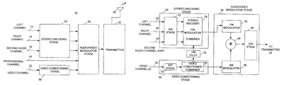
- FIG. 1 is a block diagram representing a television signal transmission system configured to transmit a television broadcast signal directly through a digital combination without an IF step.
- FIG. 2 is a block diagram representing a television receiver system that is configured to receive and decode the broadcast signal sent by a television signal transmission system, such as that shown in FIG. 1 .
- FIG. 3 is a block diagram representing a portion of the television signal transmission system shown in FIG. 1 that combines a digital stereo encoder with a digital video conditioner and a digital modulator functional block according to the teaching herein.
- a functional block diagram of a television signal transmitter 10 that processes audio and video content of a television signal for transmission to one or more reception sites.
- the transmitter 10 produces a broadcast television signal directly at a radio frequency through digital combination without an intermediate frequency (IF) step.
- the audio content processed by the transmitter 10 may comply with various television standards such as the BTSC standard, the A2/Zweiton Standard, the EIA-J standard, the NICAM standard, the Dual FM standard, and others.
- the video content may comply with various standards such as the NTSC standard, the PAL standard, and the SECAM standard, and variations of these.
- Variations of the PAL standard include the PAL I, B, G H, M, D, and N variations.
- Variations of the SECAM standard include the SECAM D, K, L, B, and G variations.
- a digital stereo audio encoding stage 24 is combined with a digital video conditioning stage 60 and a digital audio/video modulator stage 26 .
- Left and right audio signals are provided on respective lines (e.g., conductive wires, cables, buses, etc.) 12 and 14 .
- a secondary audio program (e.g., SAP) signal that includes additional signal information content (e.g., alternative languages, either as audio signals or subtitles for video viewing, etc.) may be provided by line 16 .
- a fourth line 18 may provide a professional channel that would typically be used by broadcast television and cable television companies.
- video channel signals are provided by a line 20 to a transmitter 22 .
- Signals from the audio channels are digitized and encoded to form stereo signals and then prepared for transmission.
- the stereo encoding stage 24 may produce sum and difference signals from the left and right channel signals and may use a pilot signal from the video signal(s).
- the stereo encoding stage may employ suitable stereo encoding such as described in U.S. Pat. No. 6,259,482, the contents of which are incorporated herein by reference.
- Video conditioning stage 60 may perform signal conditioning on digitized video signals of channel 20 .
- Audio/video modulator stage 26 may receive the processed audio signals, e.g., sum signal and difference signals, and video signals and prepare the signals for transmission. Additional signals present for some stereo standards, e.g., a professional channel for BTSC, may also be prepared for transmission by audio/video modulator stage 26 . In this exemplary design, audio/video modulator stage 26 combines and provides the audio and video signals to transmitter 22 .
- the audio/video modulator stage 26 frequency modulates the stereo audio signals, placing them directly at a desired audio transmission signal frequency.
- the video signals are amplitude modulated by the audio/video modulator stage 26 and placed at a desired video transmission signal frequency.
- the audio and video signals at their respective transmission frequencies are then digitally combined, forming a complete television broadcast signal.
- Operations of the audio/video modulator stage 26 may be performed by utilizing a digital signal processor (DSP) or similar hardware techniques known to one skilled in the art of television audio and video signal processing.
- DSP digital signal processor
- Software techniques known to one skilled in the art may likewise be used.
- the signals of the broadcast channel may subsequently be transmitted, e.g., provided, for example, to an antenna (or an antenna system) 28 , when the latter is needed for transmitting the signal.
- an antenna or an antenna system
- Various signal transmitting techniques known to one skilled in the art of television systems and telecommunications may be implemented by transmitter 22 and when needed antenna 28 .
- transmitter 22 may be incorporated into a cable television system (where an antenna is not needed), a broadcast television system, or other similar television audio and video content generation system.
- FIG. 2 is a block diagram representing a television receiver system 30 that is configured to receive and decode a television broadcast signal sent by a television signal transmission system, such as that shown in FIG. 1 .
- the television receiver system 30 may include an antenna 32 (or a system of antennas) for receiving stereo compatible broadcast signals from television transmission systems such as system 10 (shown in FIG. 1 ).
- the system 30 is shown configured to receive BTSC audio signals but other stereo standards may of course be used.
- the received signals are preferably provided to a receiver 34 , the latter being capable of detecting and isolating the television transmission signals.
- receiver 34 may receive the stereo compatible signals from another television signal transmission technique known to one skilled in the art of television signal broadcasting.
- the television signals may be provided to receiver 34 over a cable television system or a satellite television network.
- receiver 34 Upon receiving the television signals, receiver 34 conditions (e.g., amplifies, filters, frequency scales, etc.) the signals and separates the video signals and the audio signals from the transmission signals.
- the video content is preferably provided to a video processing system 36 that prepares the video content contained in the video signals for presentation on a screen (e.g., a cathode ray tube, etc.) associated with the television receiver system 30 .
- Signals containing the separate audio content are preferably provided to a demodulator stage 38 that e.g., removes the modulation applied to the audio signals by television transmission system 10 .
- the demodulated audio signals are preferably provided to a stereo, e.g., BTSC, decoder 40 that appropriately decodes each signal.
- a stereo e.g., BTSC
- the SAP channel signal is preferably provided a SAP signal decoder 42 and the professional channel signal is preferably provided to a professional channel decoder 44 .
- a demodulated sum signal (i.e., L+R signal) is preferably provided to a de-emphasis unit 46 that processes the sum signal in a substantially complementary fashion to the processing by stereo encoding stage 24 shown in FIG. 1 .
- the signal is preferably provided to a matrix 48 for separating the left and right channel audio signals.
- the difference signal (i.e., L ⁇ R) is also demodulated by demodulation stage 38 and is preferably provided to a stereo, e.g., BTSC, expander 50 that is included in stereo decoder 40 .
- Stereo expander 50 complies with a suitable stereo standard, such as the BTSC standard, to condition the difference signal.
- Matrix 48 receives the difference signal from stereo expander 50 and with the sum signal, separates the right and left audio signals into independent signals (identified in the figure as “L” and “R”). By separating the signals, the individual right and left channel audio signals may be conditioned and provided to separate speakers.
- both the left and right audio signals are provided to an amplifier stage 52 that applies the same (or different) gains to each signal prior to providing the appropriate signals to a speaker 54 for broadcasting the left channel audio signal content and another speaker 56 for broadcasting the right channel audio content.
- Digitized audio signals from a left, right, and SAP channel are preferably provided over respective lines 62 , 64 , and 66 to stereo encoder 58 .
- signals from the left and right audio channels are preferably provided to a matrix, such as described in U.S. Pat. No. 6,259,482, the contents of which are incorporated herein by reference.
- the matrix calculates a sum signal (e.g., L+R) and a difference signal (e.g., L ⁇ R) from the digital audio signals.
- a sum signal e.g., L+R
- a difference signal e.g., L ⁇ R
- operations of the matrix are performed by utilizing a digital signal processor (DSP) or similar hardware techniques known to one skilled in the art of television audio and video signal processing.
- the operations of the matrix may be partially or completely implemented with software techniques known to one skilled in the art.
- FIG. 3 is a block diagram representing a detailed portion of the television signal transmission system shown in FIG. 1 .
- Left and right audio signals 62 , 64 are digitized by an analog-to-digital stage (A/D) 70 within the stereo encoding stage 24 .
- A/D analog-to-digital stage
- One or more suitable D/A converters may be used for this process.
- the digitized audio signal may then be encoded according to the relevant stereo standard specification, e.g., BTSC, for example as described in previously mentioned U.S. Pat. No. 6,259,482.
- an incoming SAP signal 66 may also digitized, FM-modulated, and combined with the stereo data to produce a combined audio signal.
- a stereo pilot signal 78 required for the stereo encoding process may extracted from the incoming video signal on the video channel 90 .
- An FM modulator 82 within the audio/video modulator stage 26 places the combined audio signal directly at the carrier frequency at the desired final audio signal.
- the audio frequency carrier for cable channel three according to the NTSC standard is located at the 65.75 MHz incrementally related carrier (IRC).
- the audio frequency carrier for cable channel four would be 71.75 MHz (IRC). In this way, the use of an intermediate frequency (IF) can be avoided.
- Video conditioner/combiner 80 may be used to condition and combine the input video signals, producing a broadcast video signal.
- video conditioner/combiner 80 may combine the signals to form a CVBS signal.
- the video conditioner/combiner 80 may act to limit the bandwidth of the combined signal and perform other signal conditioning, e.g., back-porch referenced DC-restoration.
- a digital AM modulator 86 can place the video at the proper video signal frequency.
- the video carrier frequency for NTSC cable channel three is 61.25 MHz (IRC)
- the video carrier frequency for NTSC cable channel four is 67.25 MHz (IRC).
- the audio and video signals may be digitally combined by a summer 84 to create a complete transmission signal.
- the resulting combined digital television broadcast signal may then be passed through a digital-to-analog converter (DAC) 88 and then placed on the transmission medium, e.g., line to transmitter 22 .
- DAC digital-to-analog converter
- Appropriate anti-aliasing filters and line amplifiers may be used to improve signal quality and boost the power of the.
- the DAC is preferably a high-speed device.
- aspects of the present disclosure may offer advantages over the prior art. Aspects may provide for the production of television broadcast signals directly at a signal frequency of interest without the need to use any intermediate frequency (IF) stages. Such architectures can provide for decreased costs and increased reliability for the television broadcasting.
- IF intermediate frequency
- stereo encoders, modulators, summers, and converters have been described as being implemented with hardware components (and may be manufactured, for example, as a single integrated circuit, and chip set, a hybrid circuit, or a circuit with discrete components), however, in some arrangements one or more operational portions of the stereo encoders, modulators, summers, and converters stages may be implemented in software or a combination of both.
- Software code may be provided in a suitable language, e.g., Verilog. This code may be stored on and retrieved from a storage device (e.g., RAM, ROM, hard-drive, CD-ROM, etc.) and executed on one or more general purpose processors and/or specialized processors such as a dedicated DSP.
- audio content may comply with various television standards such as the BTSC standard, the A2/Zweiton Standard, the EIA-J standard, the NICAM standard, the Dual FM standard, and others.
- the video content may comply with various standards such as the NTSC standard, the PAL standard, and the SECAM standard, and variations of these.
- Variations of the PAL standard include the PAL I, B, G, H, M, D, and N variations
- variations of the SECAM standard include the SECAM D, K, L, B, and G variations.
Abstract
Description
-
- (1) Y, B-Y, R-Y: Luma and color-difference signals.
- (2) Y, Pr, Pb: Pr and Pb are scaled versions of B-Y and R-Y.
- (3) Y, Cr, Cb: Digital signal equivalent to Y, Pr, Pb.
- (4) Y, U, V: intermediate quadrature signals used in the formation of composite and Y/C signals.
Claims (14)
Priority Applications (3)
| Application Number | Priority Date | Filing Date | Title |
|---|---|---|---|
| US12/627,317 US7830452B2 (en) | 2004-09-17 | 2009-11-30 | Direct digital encoding and radio frequency modulation for broadcast television applications |
| US12/942,796 US8264606B2 (en) | 2004-09-17 | 2010-11-09 | Direct digital encoding and radio frequency modulation for broadcast television applications |
| US13/610,493 US20130010193A1 (en) | 2004-09-17 | 2012-09-11 | Direct Digital Encoding and Radio Frequency Modulation for Broadcast Television Applications |
Applications Claiming Priority (3)
| Application Number | Priority Date | Filing Date | Title |
|---|---|---|---|
| US61091504P | 2004-09-17 | 2004-09-17 | |
| US11/228,066 US7719616B2 (en) | 2004-09-17 | 2005-09-16 | Direct digital encoding and radio frequency modulation for broadcast television application |
| US12/627,317 US7830452B2 (en) | 2004-09-17 | 2009-11-30 | Direct digital encoding and radio frequency modulation for broadcast television applications |
Related Parent Applications (1)
| Application Number | Title | Priority Date | Filing Date |
|---|---|---|---|
| US11/228,066 Continuation US7719616B2 (en) | 2004-09-17 | 2005-09-16 | Direct digital encoding and radio frequency modulation for broadcast television application |
Related Child Applications (1)
| Application Number | Title | Priority Date | Filing Date |
|---|---|---|---|
| US12/942,796 Continuation US8264606B2 (en) | 2004-09-17 | 2010-11-09 | Direct digital encoding and radio frequency modulation for broadcast television applications |
Publications (2)
| Publication Number | Publication Date |
|---|---|
| US20100073558A1 US20100073558A1 (en) | 2010-03-25 |
| US7830452B2 true US7830452B2 (en) | 2010-11-09 |
Family
ID=36090551
Family Applications (4)
| Application Number | Title | Priority Date | Filing Date |
|---|---|---|---|
| US11/228,066 Expired - Fee Related US7719616B2 (en) | 2004-09-17 | 2005-09-16 | Direct digital encoding and radio frequency modulation for broadcast television application |
| US12/627,317 Expired - Fee Related US7830452B2 (en) | 2004-09-17 | 2009-11-30 | Direct digital encoding and radio frequency modulation for broadcast television applications |
| US12/942,796 Expired - Fee Related US8264606B2 (en) | 2004-09-17 | 2010-11-09 | Direct digital encoding and radio frequency modulation for broadcast television applications |
| US13/610,493 Abandoned US20130010193A1 (en) | 2004-09-17 | 2012-09-11 | Direct Digital Encoding and Radio Frequency Modulation for Broadcast Television Applications |
Family Applications Before (1)
| Application Number | Title | Priority Date | Filing Date |
|---|---|---|---|
| US11/228,066 Expired - Fee Related US7719616B2 (en) | 2004-09-17 | 2005-09-16 | Direct digital encoding and radio frequency modulation for broadcast television application |
Family Applications After (2)
| Application Number | Title | Priority Date | Filing Date |
|---|---|---|---|
| US12/942,796 Expired - Fee Related US8264606B2 (en) | 2004-09-17 | 2010-11-09 | Direct digital encoding and radio frequency modulation for broadcast television applications |
| US13/610,493 Abandoned US20130010193A1 (en) | 2004-09-17 | 2012-09-11 | Direct Digital Encoding and Radio Frequency Modulation for Broadcast Television Applications |
Country Status (10)
| Country | Link |
|---|---|
| US (4) | US7719616B2 (en) |
| CN (1) | CN101147397B (en) |
| AR (1) | AR050651A1 (en) |
| BR (1) | BRPI0515438A (en) |
| CA (1) | CA2580613A1 (en) |
| HK (1) | HK1121316A1 (en) |
| MX (1) | MX2007003153A (en) |
| MY (1) | MY143856A (en) |
| TW (1) | TWI392363B (en) |
| WO (1) | WO2006034142A2 (en) |
Cited By (1)
| Publication number | Priority date | Publication date | Assignee | Title |
|---|---|---|---|---|
| US20090096920A1 (en) * | 2007-10-16 | 2009-04-16 | Fan Xu | Method and system for integrated multi-standard tv audio encoder |
Families Citing this family (9)
| Publication number | Priority date | Publication date | Assignee | Title |
|---|---|---|---|---|
| BRPI0515438A (en) | 2004-09-17 | 2008-07-29 | That Corp | direct digital coding and radio frequency modulation to broadcast television application |
| US7706312B1 (en) * | 2006-06-09 | 2010-04-27 | Marvell International Ltd. | Digital sub-carrier signal recovery based on pilot zero-crossing |
| US20070297454A1 (en) * | 2006-06-21 | 2007-12-27 | Brothers Thomas J | Systems and methods for multicasting audio |
| CN102006432A (en) * | 2010-11-19 | 2011-04-06 | 中兴通讯股份有限公司 | Device, terminal and method for transmitting RF audio/video signals |
| US20120314777A1 (en) * | 2011-06-13 | 2012-12-13 | Ati Technologies Ulc | Method and apparatus for generating a display data stream for transmission to a remote display |
| US9588566B2 (en) * | 2011-09-07 | 2017-03-07 | Texas Instruments Incorporated | Programmable time delay and signal polarity improving transceiver signal-to-noise metric |
| KR102208077B1 (en) * | 2014-01-02 | 2021-01-28 | 엘지전자 주식회사 | Video display device and operating method thereof |
| US20170126341A1 (en) * | 2015-10-29 | 2017-05-04 | Electronics And Telecommunications Research Institute | Fam transmitting apparatus and method for combining fm signal and digital modulated am signal |
| CN110213004A (en) * | 2019-05-20 | 2019-09-06 | 雷欧尼斯(北京)信息技术有限公司 | Immersion viewing method and device based on digital audio broadcasting mode |
Citations (31)
| Publication number | Priority date | Publication date | Assignee | Title |
|---|---|---|---|---|
| US4249214A (en) * | 1979-03-23 | 1981-02-03 | Rca Corporation | Exciter having incidental phase correction compensation in consonance with output power level |
| US4339772A (en) * | 1980-10-14 | 1982-07-13 | Zenith Radio Corporation | TV Sound Transmission system |
| US4398216A (en) * | 1980-09-19 | 1983-08-09 | Telease, Inc. | Multiple signal transmission method and system, particularly for television |
| JPH01115147A (en) | 1987-10-28 | 1989-05-08 | Nec Corp | Manufacture of cooling device for integrated circuit |
| US4905087A (en) * | 1988-08-29 | 1990-02-27 | The United States Of American As Represented By The United States Department Of Energy | UHF FM receiver having improved frequency stability and low RFI emission |
| US5337196A (en) * | 1991-01-31 | 1994-08-09 | Samsung Electronics Co., Ltd. | Stereo/multivoice recording and reproducing video tape recorder including a decoder developing a switch control signal |
| US5555024A (en) * | 1994-12-23 | 1996-09-10 | Samsung Electronics Co., Ltd. | Transmitters for burying digital signals within the trace and retrace intervals of NTSC television signals |
| US5563664A (en) * | 1994-01-05 | 1996-10-08 | Samsung Electronics Co., Ltd. | Pre-frame-comb as well as pre-line-comb partial-response filtering of BPSK buried in a TV signal |
| US5604929A (en) * | 1995-04-21 | 1997-02-18 | Rockwell International | System for correcting quadrature gain and phase errors in a direct conversion single sideband receiver independent of the character of the modulated signal |
| US5796842A (en) * | 1996-06-07 | 1998-08-18 | That Corporation | BTSC encoder |
| JPH1115147A (en) | 1997-06-23 | 1999-01-22 | Hitachi Chem Co Ltd | Production of color image forming material photosensitive element and color filter |
| US5877821A (en) * | 1997-01-30 | 1999-03-02 | Motorola, Inc. | Multimedia input and control apparatus and method for multimedia communications |
| US6037740A (en) * | 1995-07-05 | 2000-03-14 | The University Of Warwick | Switched reluctance electric machine system |
| US6037993A (en) * | 1997-03-17 | 2000-03-14 | Antec Corporation | Digital BTSC compander system |
| US6192086B1 (en) * | 1999-01-14 | 2001-02-20 | Antec Corporation | Digital sub-systems and building blocks for a mostly digital low-cost BTSC compatible encoder |
| US6259482B1 (en) * | 1998-03-11 | 2001-07-10 | Matthew F. Easley | Digital BTSC compander system |
| US6272226B1 (en) * | 1997-04-02 | 2001-08-07 | Scientific-Atlanta, Inc. | Apparatus and method for masking audio signals in a signal distribution system |
| US6281813B1 (en) * | 1999-07-09 | 2001-08-28 | Micronas Gmbh | Circuit for decoding an analog audio signal |
| US6417890B1 (en) * | 1999-10-21 | 2002-07-09 | General Electric Company | Modulation of pilot tone amplitude in DTV broadcast for faster channel acquisition |
| US6433835B1 (en) * | 1998-04-17 | 2002-08-13 | Encamera Sciences Corporation | Expanded information capacity for existing communication transmission systems |
| US6549242B1 (en) * | 1997-04-04 | 2003-04-15 | Harris Corporation | Combining adjacent TV channels for transmission by a common antenna |
| US6588867B1 (en) * | 1999-02-18 | 2003-07-08 | Arris International, Inc. | Reciprocal index lookup for BTSC compatible coefficients |
| US20040042621A1 (en) * | 2002-08-29 | 2004-03-04 | Peracom Networks, Inc. | Multichannel television sound (MTS) stereo television encoder |
| US20050135630A1 (en) * | 2003-12-23 | 2005-06-23 | Luciano Zoso | BTSC encoder and integrated circuit |
| US20060026661A1 (en) * | 2004-05-21 | 2006-02-02 | Broadcom Corporation | Integrated set-top box |
| WO2006034142A2 (en) | 2004-09-17 | 2006-03-30 | That Corporation | Direct digital encoding and radio frequency modulation for broadcast television application |
| US20060292980A1 (en) * | 2001-09-28 | 2006-12-28 | Marcos Alba Fernando | Remotely configurable radio audience loyalty-generating and pick-up devices and broaucast network system |
| US20080106651A1 (en) * | 2004-02-06 | 2008-05-08 | Maneesh Goyal | Method and system for an integrated vsb/qam/ntsc/oob plug-and-play dtv receiver |
| US7425995B2 (en) * | 2003-02-28 | 2008-09-16 | Silicon Laboratories, Inc. | Tuner using a direct digital frequency synthesizer, television receiver using such a tuner, and method therefor |
| US7539316B2 (en) * | 2004-03-24 | 2009-05-26 | That Corporation | Configurable filter for processing television audio signals |
| US7639307B2 (en) * | 2004-08-03 | 2009-12-29 | That Corporation | Up-sampling television audio signals for encoding |
Family Cites Families (11)
| Publication number | Priority date | Publication date | Assignee | Title |
|---|---|---|---|---|
| CA1182204A (en) * | 1980-10-14 | 1985-02-05 | Carl G. Eilers | Tv sound transmission system |
| US4563702A (en) * | 1983-05-27 | 1986-01-07 | M/A-Com Linkabit, Inc. | Video signal scrambling and descrambling systems |
| US4821097A (en) * | 1987-03-05 | 1989-04-11 | General Instrument Corporation | Apparatus and method for providing digital audio on the sound carrier of a standard television signal |
| US5584051A (en) * | 1991-11-01 | 1996-12-10 | Thomson Consumer Electronics Sales Gmbh | Radio broadcast transmission system and receiver for incompatible signal formats, and method therefor |
| US6147713A (en) * | 1998-03-09 | 2000-11-14 | General Instrument Corporation | Digital signal processor for multistandard television reception |
| US6430227B1 (en) * | 1998-03-27 | 2002-08-06 | Ibiquity Digital Corporation | FM in-band-on-channel digital audio broadcasting method and system |
| CN1233917A (en) * | 1998-04-30 | 1999-11-03 | 陈意辉 | Multiple and super high frequency TV transmission system |
| CN1128538C (en) * | 1998-07-18 | 2003-11-19 | 三星电子株式会社 | NTSC video signal receivers with reduced sensitivity to interference from Co-channel digital television signals |
| US6400416B1 (en) * | 1999-04-09 | 2002-06-04 | Maxim Integrated Products | Single-chip digital cable TV/cable modem tuner IC |
| CN2489526Y (en) * | 2001-07-13 | 2002-05-01 | 安徽四创电子股份有限公司 | Digital integral tuner for direct broadcasting satellite television |
| TW574825B (en) * | 2002-09-13 | 2004-02-01 | Airwave Technologies Inc | Transceiver of triple modulation threefold signal |
-
2005
- 2005-09-16 BR BRPI0515438-3A patent/BRPI0515438A/en not_active IP Right Cessation
- 2005-09-16 CN CN2005800383667A patent/CN101147397B/en not_active Expired - Fee Related
- 2005-09-16 CA CA002580613A patent/CA2580613A1/en not_active Abandoned
- 2005-09-16 WO PCT/US2005/033391 patent/WO2006034142A2/en active Application Filing
- 2005-09-16 MX MX2007003153A patent/MX2007003153A/en active IP Right Grant
- 2005-09-16 US US11/228,066 patent/US7719616B2/en not_active Expired - Fee Related
- 2005-09-19 MY MYPI20054380A patent/MY143856A/en unknown
- 2005-09-19 TW TW094132377A patent/TWI392363B/en not_active IP Right Cessation
- 2005-09-20 AR ARP050103919A patent/AR050651A1/en active IP Right Grant
-
2008
- 2008-09-18 HK HK08110331.9A patent/HK1121316A1/en not_active IP Right Cessation
-
2009
- 2009-11-30 US US12/627,317 patent/US7830452B2/en not_active Expired - Fee Related
-
2010
- 2010-11-09 US US12/942,796 patent/US8264606B2/en not_active Expired - Fee Related
-
2012
- 2012-09-11 US US13/610,493 patent/US20130010193A1/en not_active Abandoned
Patent Citations (34)
| Publication number | Priority date | Publication date | Assignee | Title |
|---|---|---|---|---|
| US4249214A (en) * | 1979-03-23 | 1981-02-03 | Rca Corporation | Exciter having incidental phase correction compensation in consonance with output power level |
| US4398216A (en) * | 1980-09-19 | 1983-08-09 | Telease, Inc. | Multiple signal transmission method and system, particularly for television |
| US4339772A (en) * | 1980-10-14 | 1982-07-13 | Zenith Radio Corporation | TV Sound Transmission system |
| JPH01115147A (en) | 1987-10-28 | 1989-05-08 | Nec Corp | Manufacture of cooling device for integrated circuit |
| US4905087A (en) * | 1988-08-29 | 1990-02-27 | The United States Of American As Represented By The United States Department Of Energy | UHF FM receiver having improved frequency stability and low RFI emission |
| US5337196A (en) * | 1991-01-31 | 1994-08-09 | Samsung Electronics Co., Ltd. | Stereo/multivoice recording and reproducing video tape recorder including a decoder developing a switch control signal |
| US5563664A (en) * | 1994-01-05 | 1996-10-08 | Samsung Electronics Co., Ltd. | Pre-frame-comb as well as pre-line-comb partial-response filtering of BPSK buried in a TV signal |
| US5646698A (en) * | 1994-01-05 | 1997-07-08 | Samsung Electronics Co., Ltd. | Pre-frame-comb as well as "pre-line-comb" partial-response filtering of BPSK buried in a TV signal |
| US5555024A (en) * | 1994-12-23 | 1996-09-10 | Samsung Electronics Co., Ltd. | Transmitters for burying digital signals within the trace and retrace intervals of NTSC television signals |
| US5604929A (en) * | 1995-04-21 | 1997-02-18 | Rockwell International | System for correcting quadrature gain and phase errors in a direct conversion single sideband receiver independent of the character of the modulated signal |
| US6037740A (en) * | 1995-07-05 | 2000-03-14 | The University Of Warwick | Switched reluctance electric machine system |
| US5796842A (en) * | 1996-06-07 | 1998-08-18 | That Corporation | BTSC encoder |
| US6118879A (en) * | 1996-06-07 | 2000-09-12 | That Corporation | BTSC encoder |
| US5877821A (en) * | 1997-01-30 | 1999-03-02 | Motorola, Inc. | Multimedia input and control apparatus and method for multimedia communications |
| US6037993A (en) * | 1997-03-17 | 2000-03-14 | Antec Corporation | Digital BTSC compander system |
| US6272226B1 (en) * | 1997-04-02 | 2001-08-07 | Scientific-Atlanta, Inc. | Apparatus and method for masking audio signals in a signal distribution system |
| US6549242B1 (en) * | 1997-04-04 | 2003-04-15 | Harris Corporation | Combining adjacent TV channels for transmission by a common antenna |
| JPH1115147A (en) | 1997-06-23 | 1999-01-22 | Hitachi Chem Co Ltd | Production of color image forming material photosensitive element and color filter |
| US6259482B1 (en) * | 1998-03-11 | 2001-07-10 | Matthew F. Easley | Digital BTSC compander system |
| US6433835B1 (en) * | 1998-04-17 | 2002-08-13 | Encamera Sciences Corporation | Expanded information capacity for existing communication transmission systems |
| US6192086B1 (en) * | 1999-01-14 | 2001-02-20 | Antec Corporation | Digital sub-systems and building blocks for a mostly digital low-cost BTSC compatible encoder |
| US6588867B1 (en) * | 1999-02-18 | 2003-07-08 | Arris International, Inc. | Reciprocal index lookup for BTSC compatible coefficients |
| US6281813B1 (en) * | 1999-07-09 | 2001-08-28 | Micronas Gmbh | Circuit for decoding an analog audio signal |
| US6417890B1 (en) * | 1999-10-21 | 2002-07-09 | General Electric Company | Modulation of pilot tone amplitude in DTV broadcast for faster channel acquisition |
| US20060292980A1 (en) * | 2001-09-28 | 2006-12-28 | Marcos Alba Fernando | Remotely configurable radio audience loyalty-generating and pick-up devices and broaucast network system |
| US20040042621A1 (en) * | 2002-08-29 | 2004-03-04 | Peracom Networks, Inc. | Multichannel television sound (MTS) stereo television encoder |
| US7425995B2 (en) * | 2003-02-28 | 2008-09-16 | Silicon Laboratories, Inc. | Tuner using a direct digital frequency synthesizer, television receiver using such a tuner, and method therefor |
| US20050135630A1 (en) * | 2003-12-23 | 2005-06-23 | Luciano Zoso | BTSC encoder and integrated circuit |
| US20080106651A1 (en) * | 2004-02-06 | 2008-05-08 | Maneesh Goyal | Method and system for an integrated vsb/qam/ntsc/oob plug-and-play dtv receiver |
| US7539316B2 (en) * | 2004-03-24 | 2009-05-26 | That Corporation | Configurable filter for processing television audio signals |
| US20090231491A1 (en) * | 2004-03-24 | 2009-09-17 | Barnhill Matthew S | Configurable Filter for Processing Television Audio Signals |
| US20060026661A1 (en) * | 2004-05-21 | 2006-02-02 | Broadcom Corporation | Integrated set-top box |
| US7639307B2 (en) * | 2004-08-03 | 2009-12-29 | That Corporation | Up-sampling television audio signals for encoding |
| WO2006034142A2 (en) | 2004-09-17 | 2006-03-30 | That Corporation | Direct digital encoding and radio frequency modulation for broadcast television application |
Non-Patent Citations (2)
| Title |
|---|
| English Translation of Mexican Office Action for related MX Application no. MX/a/2007/003153, 1 page. |
| Text of First Office Action of related CN Application No. 2005800383667, 10 pages. |
Cited By (1)
| Publication number | Priority date | Publication date | Assignee | Title |
|---|---|---|---|---|
| US20090096920A1 (en) * | 2007-10-16 | 2009-04-16 | Fan Xu | Method and system for integrated multi-standard tv audio encoder |
Also Published As
| Publication number | Publication date |
|---|---|
| MX2007003153A (en) | 2007-06-05 |
| CN101147397B (en) | 2011-06-15 |
| AR050651A1 (en) | 2006-11-08 |
| WO2006034142A2 (en) | 2006-03-30 |
| CA2580613A1 (en) | 2006-03-30 |
| TWI392363B (en) | 2013-04-01 |
| US8264606B2 (en) | 2012-09-11 |
| HK1121316A1 (en) | 2009-04-17 |
| TW200623878A (en) | 2006-07-01 |
| US20130010193A1 (en) | 2013-01-10 |
| US20110050996A1 (en) | 2011-03-03 |
| WO2006034142A3 (en) | 2006-10-05 |
| BRPI0515438A (en) | 2008-07-29 |
| US7719616B2 (en) | 2010-05-18 |
| CN101147397A (en) | 2008-03-19 |
| US20060061684A1 (en) | 2006-03-23 |
| MY143856A (en) | 2011-07-15 |
| US20100073558A1 (en) | 2010-03-25 |
Similar Documents
| Publication | Publication Date | Title |
|---|---|---|
| US7830452B2 (en) | Direct digital encoding and radio frequency modulation for broadcast television applications | |
| EP0144770B1 (en) | Catv signal transmitting system and related receiving system | |
| US4139866A (en) | Stereophonic television sound transmission system | |
| US4646150A (en) | Apparatus and method for stereo television sound | |
| US4048654A (en) | Stereophonic television sound transmission system | |
| US4532540A (en) | Teletext set-top converter with transparent mode | |
| US7929054B2 (en) | Up-sampling television audio signals for encoding | |
| US6122380A (en) | Apparatus and method of providing stereo television audio signals | |
| US20090096920A1 (en) | Method and system for integrated multi-standard tv audio encoder | |
| US20050036074A1 (en) | Method and system for a digital interface for TV stereo audio decoding | |
| JP3417161B2 (en) | On-screen synthesis device for digital broadcast receiver | |
| JPH06189273A (en) | Transmitted signal reproducing device and signal reproducing device | |
| JPS6016153B2 (en) | Multiplex broadcast reception adapter | |
| JP2706009B2 (en) | Output device of HDTV receiver | |
| EP0319109A1 (en) | TV broadcasting system for the transmission of a time-division multiplex television signal | |
| JP2888549B2 (en) | Multi-channel audio output device | |
| Buhse | Application proposals for multistandard sound TV-receivers | |
| JPH02299399A (en) | High vision voice receiver | |
| JPH07184169A (en) | High definition television signal reception processing circuit | |
| JPH03268690A (en) | Catv converter | |
| JPH07284040A (en) | Satellite broadcasting receiver | |
| JPH04322578A (en) | Audio selecting device | |
| JPS5892186A (en) | Color television receiver incorporating video disc player | |
| JPH04369177A (en) | High definition television receiver | |
| JPH06296280A (en) | Image reproducing device |
Legal Events
| Date | Code | Title | Description |
|---|---|---|---|
| AS | Assignment |
Owner name: THAT CORPORATION,MASSACHUSETTS Free format text: ASSIGNMENT OF ASSIGNORS INTEREST;ASSIGNORS:EASLEY, MATTHEW;BARNHILL, MATTHEW S.;KAY, W. KEVIN;SIGNING DATES FROM 20051101 TO 20051107;REEL/FRAME:023598/0856 |
|
| AS | Assignment |
Owner name: MIDDLESEX SAVINGS BANK, MASSACHUSETTS Free format text: SECURITY AGREEMENT;ASSIGNOR:THAT CORPORATION;REEL/FRAME:025846/0878 Effective date: 20100825 |
|
| AS | Assignment |
Owner name: MIDDLESEX SAVINGS BANK, MASSACHUSETTS Free format text: ASSIGNMENT OF ASSIGNORS INTEREST;ASSIGNOR:THAT CORPORATION;REEL/FRAME:032289/0838 Effective date: 20140214 |
|
| REMI | Maintenance fee reminder mailed | ||
| LAPS | Lapse for failure to pay maintenance fees | ||
| AS | Assignment |
Owner name: MIDDLESEX SAVINGS BANK, MASSACHUSETTS Free format text: CORRECTIVE ASSIGNMENT TO CORRECT THE NATURE OF CONVEYANCE PREVIOUSLY RECORDED AT REEL: 032289 FRAME: 0838. ASSIGNOR(S) HEREBY CONFIRMS THE SECURITY INTEREST;ASSIGNOR:THAT CORPORATION;REEL/FRAME:034347/0623 Effective date: 20140214 |
|
| STCH | Information on status: patent discontinuation |
Free format text: PATENT EXPIRED DUE TO NONPAYMENT OF MAINTENANCE FEES UNDER 37 CFR 1.362 |
|
| FP | Expired due to failure to pay maintenance fee |
Effective date: 20141109 |
|
| AS | Assignment |
Owner name: MIDDLESEX SAVINGS BANK, MASSACHUSETTS Free format text: ASSIGNMENT OF ASSIGNORS INTEREST;ASSIGNOR:THAT CORPORATION;REEL/FRAME:034884/0885 Effective date: 20100825 |
|
| AS | Assignment |
Owner name: MIDDLESEX SAVINGS BANK, MASSACHUSETTS Free format text: CORRECTIVE ASSIGNMENT TO CORRECT THE PATENT NUMBER 6192086 WAS INCORRECTLY NOTED AS 6192088 PREVIOUSLY RECORDED ON REEL 034884 FRAME 0885. ASSIGNOR(S) HEREBY CONFIRMS THE SECURITY AGREEMENT;ASSIGNOR:THAT CORPORATION;REEL/FRAME:034954/0976 Effective date: 20100825 Owner name: MIDDLESEX SAVINGS BANK, MASSACHUSETTS Free format text: CORRECTIVE ASSIGNMENT TO CORRECT THE INCORRECT PATENT NO. 6192088 PREVIOUSLY RECORDED AT REEL: 025846 FRAME: 0878. ASSIGNOR(S) HEREBY CONFIRMS THE SECURITY AGREEMENT;ASSIGNOR:THAT CORPORATION;REEL/FRAME:035000/0761 Effective date: 20100825 |