US7844399B2 - Method and system to model materials for use in articles, such as tampons - Google Patents
Method and system to model materials for use in articles, such as tampons Download PDFInfo
- Publication number
- US7844399B2 US7844399B2 US11/635,967 US63596706A US7844399B2 US 7844399 B2 US7844399 B2 US 7844399B2 US 63596706 A US63596706 A US 63596706A US 7844399 B2 US7844399 B2 US 7844399B2
- Authority
- US
- United States
- Prior art keywords
- defining
- constitutive model
- modeling method
- moisture
- compression
- Prior art date
- Legal status (The legal status is an assumption and is not a legal conclusion. Google has not performed a legal analysis and makes no representation as to the accuracy of the status listed.)
- Expired - Fee Related, expires
Links
Images


Classifications
-
- G—PHYSICS
- G06—COMPUTING; CALCULATING OR COUNTING
- G06F—ELECTRIC DIGITAL DATA PROCESSING
- G06F30/00—Computer-aided design [CAD]
- G06F30/20—Design optimisation, verification or simulation
-
- G—PHYSICS
- G06—COMPUTING; CALCULATING OR COUNTING
- G06F—ELECTRIC DIGITAL DATA PROCESSING
- G06F2119/00—Details relating to the type or aim of the analysis or the optimisation
- G06F2119/08—Thermal analysis or thermal optimisation
Definitions
- the present disclosure generally relates to a method and a system for modeling materials for use in articles, such as tampons, including a method and a computerized system for modeling materials for use in such articles.
- a tampon is a piece of fibrous material that is shaped to be insertable into a body cavity, such as, for example, a vagina or nasal cavity.
- the tampon is disposed in a tube-shaped applicator prior to use, although an applicator need not be included in all applications.
- the user positions the tampon in the appropriate body cavity, and then disposes of the applicator, if used.
- a modeling method for a fibrous material to be made into a tampon product includes analyzing processes and conditions under which the fibrous material is made into the tampon product, determining that moisture, temperature and rate conditions should be tested according to the analysis of the processes and conditions, and testing the fibrous material under at least one of moisture, thermal or rate conditions similar to those under which the fibrous material is made into the tampon product to obtain test results.
- the modeling method further includes defining a constitutive model for the fibrous material according to the test results.
- a modeling system for a fibrous material to be made into a tampon product includes a computing device, with a processor and a data storage device, and a constitutive model for the fibrous material.
- the constitutive model is stored in the data storage device, and includes a relationship between one of stress and deformation or stress rate and rate of deformation, a yield criterion, a plastic flow rule, and an evolution equation defined according to test results from testing performed on the fibrous material under at least one of moisture, temperature or rate conditions similar to those under which the fibrous material is made into the tampon product to obtain test results.
- the computing device is programmed to perform simulations using the constitutive model to determine the state of stress for an arbitrary deformation path.
- a modeling method for a material to be made into a product includes analyzing processes and conditions under which the material is made into the product, determining test environmental conditions under which the material should be tested according to the analysis of the processes and conditions, and testing the material under test environmental conditions to obtain test results.
- the modeling method also includes defining a constitutive model for the material according to the test results.
- a modeling system for a material to be made into a product includes a computing device, comprising a processor and a data storage device, and a constitutive model for the material.
- the constitutive model is stored in the data storage device, and includes a relationship between one of stress and deformation or stress rate and rate of deformation, a yield criterion, a plastic flow rule, and an evolution equation defined according to test results from testing performed on the material under environmental conditions similar to those under which the material is made into the product to obtain test results.
- the computing device is programmed to perform simulations using the constitutive model to determine the state of stress for an arbitrary deformation path.
- FIG. 1 is a perspective view of a compression machine, a push rod, and a joined sleeve cavity mold
- FIG. 2 is an exploded view of a split cavity mold
- FIG. 3 is a side view of the split cavity mold
- FIG. 4 is an enlarged, perspective view of the joined sleeve cavity mold
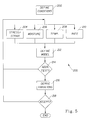
- FIG. 5 is a flowchart of a method to model a material that is made into a tampon product
- FIG. 6 is a flowchart of a method to model a material that is made into a product.
- FIG. 7 is a schematic of a system for carrying out the method of modeling a material that is made into a product, such as a tampon product.
- a model is defined for a fibrous material that is made into a tampon product.
- the method of defining a model for the fibrous material that is made into a tampon may involve certain preliminary steps and empirical steps. That is, in defining the model, the processes which the fibrous material undergoes and the conditions under which these processes are conducted may first be considered. As a consequence of this preliminary consideration, a series of tests may be outlined to gather measurements of the material under the conditions identified in the preliminary consideration (or test results). The test results may then be used to define a model, which may be a constitutive model, as explained in greater detail below.
- the model may include one or more coupled equations, which equations may be capable of being solved numerically. It may be desired to modify this model according to measurements taken during the testing, which modifications may be in the form of variations, including coefficients.
- the result of the process is a model defined for the fibrous material in question.
- the method of making a tampon generally begins with a pledget.
- pledget or “tampon pledget” are intended to be interchangeable and refer to a construction of absorbent material prior to compression of such construction into a tampon. Tampon pledgets are sometimes referred to as a tampon blank, a softwind, or a pad, and the term “pledget” is intended to include such terms as well.
- the pledget may be of a variety of shapes, sizes, materials and constructions.
- the pledget may be rectangular, trapezoidal, triangular, semi-circular, chevron-shaped, H-shaped, bowtie-shaped, or cylindrical.
- the pledget may be constructed from a similarly wide variety of liquid-absorbing materials, including synthetic and natural fibers in woven and nonwoven materials, including cotton, rayon, polyester, polyethylene, polypropylene and combinations thereof.
- the pledget may also include incorporated materials, such as superabsorbent materials including superabsorbent polymers or gelling materials and the like.
- the pledget may be defined by a single material having a single density, or may be defined by a material with a varying density or thickness.
- the tampon pledget may be of a laminar structure including at least one intermediate layer disposed between two outer layers. Further variants for the pledget are described in U.S. Publication Nos. 2003/0172504 and U.S. Pat. No. 6,740,070.
- the tampon pledget may be go through a preliminary forming step, be compressed to form a substantially cylindrical form, and then set into the final product form in a mold.
- the pledget may be rolled, spirally wound, or folded.
- Folding is characterized by at least one bend at least in a portion of the tampon pledget such that the relevant portion of the tampon pledget is positioned in a different plane than before, with the observation that the surface regions near the bend are in a different distal and angular relationship to each other after the folding has taken place.
- the preliminarily-formed pledget may then be disposed into a compressing element. See FIG. 1 .
- the compressing element is designed to compress the incoming pledget into a generally cylindrical shape. Compressing refers to pressing, compacting, or squeezing together or to reduce in size or volume as if by squeezing.
- the product of this process step is a fiber body with a high aspect ratio, i.e., a shape in which the length is greater than the diameter or width of the shape; this product may or may not contain defined circles or arcs.
- compression may be accomplished by placing the pledget into a compression jaw 150 , which may be referred to as a cross-die for flat pledgets. Initially, inner surface of the first and second pieces are spaced relative to each other. When the compression jaw is actuated, the first and second pieces are moved so that the inner surfaces are no longer spaced, but are generally abutting each other, with the preliminary-formed pledget disposed between the two pieces. The movement of the jaw may take about 0.2 seconds or less. As mentioned above, the pledget is compressed into a fiber body having a high aspect ratio shape, although other shapes are possible (e.g., rectangular, triangular, trapezoidal, and semi-circular).
- a typical cross die will typically have an open width of between about 50 and about 120 mm, and close to between about 10 and about 18 mm.
- the tampon pledget may have a lateral dimension of between about 50 and about 80 mm aligned to the closing direction of the cross die.
- closure will strain the pledget in this direction between about 25 and about 85%, more typically between about 50 and about 85%, or even between about 70 and about 85%.
- the accompanying compression rate can be between about 350 and about 600 mm/s, which can translate into a strain rate of between about 6/s and about 17/s.
- the pledget density of about 0.05 to about 0.1 g/cc will thus increase to between about 0.3 and about 0.5 g/cc for the cylindrically shaped compressed fiber body, in a typical application.
- the fiber body may then be transferred into a tampon-forming mold, although a fixed-pressure device could also be used. See FIGS. 2 and 3 .
- the tampon sets to a desired shape and dimension, such that the final tampon is able to remain in a self-sustaining form.
- the ability to remain in a self-sustaining form refers to the degree to which the tampon retains the compression applied to the absorbent material of the tampon pledget such that in the subsequent absence of the external forces, the resulting tampon will retain its general shape and size.
- the resulting tampon's total volume growth subsequent to removal of the external forces may be no greater than about 50% of the external force-restrained shape.
- growth may be less than about 25%, while in still other embodiments is may not exceed about 10% of the external force-restrained shape when observed at ambient room conditions of about 22 C.-24 C. and about 50% relative humidity.
- the compressed fiber body is transferred into the transfer end (or ingress port) of a mold 160 , for example a split cavity mold (see FIGS. 1-4 ), using a transfer member 170 , such as a push rod (see FIG. 1 ), which may affect the transfer in about 0.2 seconds or less.
- a transfer member 170 such as a push rod (see FIG. 1 ), which may affect the transfer in about 0.2 seconds or less.
- a pushrod will generally be sized smaller than the cross die and mold diameters, and may be shaped on the tip.
- the pushrod 170 may be used to axially compress the tampon in the mold.
- and laterally compressed fiber body may start with an initial length of between about 40 and about 100 mm, and be axially compressed within the mold 60 to between about 25 and about 50 mm, resulting in a strain of between about 25 and about 75%.
- the pushrod will create a compression rate of about 500 mm/s, which may translate into a strain rate of between about 4/s and about 14/s.
- shearing may also occur within the material.
- the process may be conducted under controlled temperature conditions to assist the process.
- the setting of the tampon may be assisted by the introduction of heat, which heat-setting may occur while the tampon is at least partially inside the mold.
- the heat may be introduced by one method or another, e.g., thermal temperature gradient conduction, microwave heating, radio-frequency heating, infrared heating, gas heating (hot air, steam) etc.
- Typical header (conductive heating) temperatures are about 260 C., and the header (not shown) may be in contact with the end of the fiber body for between about 0.1 and about 0.15 seconds.
- the mold temperature may be between about 130 C. and about 170 C. for about 15 seconds.
- the consequence of the heating step may be that the temperature of the fiber is between about 25 C. and about 200 C.
- the heat-setting may be accompanied by control of the internal moisture of the tampon, either through pre-humidification or pre-drying, to control the overall resultant self-sustaining behavior of the tampon.
- steam may be introduced for between about 0.5 and about 1 second. The steam will add between about 1% and about 3% moisture to the tampon in the first 0.5 second. Thereafter, the moisture added may dissipate through further steam treatment and subsequent heating periods. Fiber moisture levels of between about 5% and about 15%, on a dry weight basis, are desirable.
- the range of densities of the pledget/tampon throughout the processing of the material may be generally between about 0.05 g/cc and about 0.8 g/cc, although, in zones, the density may vary significantly from that in other zones, and may assume values above about 1.0 g/cc.
- Pledgets that begin at a lower density range of nominally about 0.05 g/cc to about 0.1 g/cc may be strained to a higher density on average because of the processing steps, such as with lateral compression and axial compression steps. The density even beyond the final density if overcompressing is utilized.
- the density may approach higher levels, 0.6 g/cc to 0.8 g/cc, for example, and then decrease to some lower value, 0.4 g/cc to 0.6 g/cc, for example, as the fiber rebounds from the overcompression.
- Maximum densities through the process can thus be achieved because of overcompression coupled with localized zones of density that can result in densities above 1.0 g/cc.
- the fibrous material experiences loading in tension, compression and shear as it is formed into a tampon. It may also be determined that moisture, temperature and processing rate are significant for consideration in the definition of the general form of the model and for any variations to the general model. Thus, it may be determined that the fibrous material should be tested for mechanical response (i.e., stress, strain) under tensile, compressive, and shear loadings, with variations in moisture, temperature, and rate conditions. In fact, one or more test matrices may be prepared to guide the testing.
- test matrix may be used to obtain measurements of a tampon-making material under a controlled moisture and temperature conditions:
- TD Transverse Direction
- MD Machine Direction
- Comp. Compression
- Out of Plane refers to the thickness or z-direction. The measurements would be taken at room temperature (about 22 C.-24 C.).
- test matrix may be used to obtain measurements with shear as a function of compression for a tampon-making material at varying moisture conditions:
- Moisture in Test mode Strain (in %) % Shear, TD, 20% Comp. 20, 40, 60, 80, 90 5, 10, 15 Shear, TD, 50% Comp. 20, 40, 60, 80, 90 5, 10, 15 Shear, TD, 85% Comp. 20, 40, 60, 80, 90 5, 10, 15 Shear, MD, 20% Comp. 20, 40, 60, 80, 90 5, 10, 15 Shear, MD, 50% Comp. 20, 40, 60, 80, 90 5, 10, 15 Shear, MD, 85% Comp. 20, 40, 60, 80, 90 5, 10, 15 In this table, TD is Transverse Direction, MD is Machine Direction, and Comp. is Compression.
- the measurements may be taken at room temperature (about 22 C.-24 C.), although the same tests may be performed at other temperatures, or at a plurality of different temperatures, as desired, to generate additional test results.
- a fresh sample may be used at each moisture level (and at each temperature level, if more than one temperature level is used), although the same sample may be used over the included range of strain values, with the sample run to gradually increasing levels of strain.
- the moisture content may be determined according to the following fashion.
- a series of experiments may be performed on the sample material to determine an adsorption curve and a desorption curve for the material, thereby generating a sorption isotherm for the material. These experiments may be conducted at a single temperature, or a plurality of temperatures. From the sorption isotherm, approximate humidity settings may be determined to result in an about 5%, 10%, or 15% moisture content in the material at equilibrium.
- the sample may then be conditioned in a humidity chamber at the desired humidity setting prior to use in the testing. Other methods may be used in the alternative.
- test matrix may be used to obtain stress relaxation measurements for a tampon-making material at varying thermal conditions, strains and moisture conditions:
- these may be taken at regular time intervals once the material has been permitted to equilibrate at the desired temperature and moisture, for a total elapsed time of 60 seconds. Alternatively, elapsed times other than 60 seconds may be used. Preferably, a fresh sample may be used at each level of temperature, moisture or strain.
- a general form of a constitutive model with one or more behaviors may be defined.
- the model may include the following behaviors: viscoelasticity, viscoplasticity, thermal dependency, moisture dependency, compaction (densification) and damage.
- a set of coupled, nonlinear partial differential equations may be assembled, which equations may be solved numerically (by return mapping or cutting plane algorithms, for example) to determine the state of stress for an arbitrary deformation path.
- the model may include, for example, equations relating stress and deformation or stress rate and rate of deformation, which equations may be further refined to account for viscoelasticity.
- the model may also include equations defining a yield criterion that delineates the elastic and plastic regions in stress space. Further, the model may include equations defining a plastic flow rule, which determines the amount of plastic deformation. Further, evolution equations may be included in the model.
- ⁇ tilde over ( ⁇ ) ⁇ ⁇ is the objective rate of the stress tensor
- ⁇ tilde over (M) ⁇ is the damage effect tensor
- ⁇ tilde over (C) ⁇ is the stiffness matrix.
- the damage effect tensor would be a fourth order tensor for complete anisotropy, whereas the damage effect tensor would be a scalar for isotropic damage; according an embodiment of the present disclosure, isotropic damage that includes a tension cut-off may be used.
- the stiffness matrix may be a function of temperature, moisture and stress.
- ⁇ tilde over ( ⁇ ) ⁇ (t) is the final rate dependent response of the material at time t
- ⁇ tilde over ( ⁇ ) ⁇ °(t) is the instantaneous response of the material at time t determined from the integration of the equation for ⁇ tilde over ( ⁇ ) ⁇ ⁇ , above
- ⁇ tilde over (q) ⁇ k is a series of viscoelastic relaxations, where each term is a solution to the following differential equation:
- ⁇ q ⁇ k ⁇ t + 1 ⁇ k ⁇ q ⁇ k ⁇ k ⁇ k ⁇ ⁇ ⁇ ⁇ ° ⁇ ( t ) with ⁇ being a relaxation parameter and ⁇ being the time constant.
- the yield criterion may also be defined.
- ⁇ tilde over (X) ⁇ may itself be expressed as ⁇ tilde over (K) ⁇ : ⁇ tilde over ( ⁇ ) ⁇ , where ⁇ tilde over ( ⁇ ) ⁇ is the back strain tensor.
- R may be expressed as R A +R B , where R A is the metric of yield surface size and R B is the coupling term with the back stresses (or ⁇ ( ⁇ tilde over (X) ⁇ 2 )).
- ⁇ tilde over (D) ⁇ P ⁇ tilde over (H) ⁇ i ⁇ dot over ( ⁇ ) ⁇ i ⁇ i
- ⁇ tilde over (H) ⁇ i a model-dependent homogenization term
- ⁇ i a scalar metric of plastic strain
- ⁇ i the normal to yield surface
- ⁇ f i ⁇ ⁇ ⁇
- ⁇ is the yield criterion
- ⁇ tilde over ( ⁇ ) ⁇ is stress.
- ⁇ i may take the form of a Norton or hyperbolic sine creep law to account for rate dependent plasticity, although it will be recognized that other creep laws may be used.
- evolution equations may be defined.
- the evolution may be kinematic hardening evolution, formulated as a modification of the standard Armstrong-Fredrick kinematic hardening model to include non-symmetric compressive loading and unloading behavior (i.e., the back and forth motion of the kinematic variables).
- simulations may be performed using the model, and a determination may be made, in a general sense, as to whether the model is appropriate. If not, adjustments may be made, for example, through the introduction of additional behaviors and/or couplings. Even if the model produces results that suggest that the model has included behaviors and couplings to represent the material in a general sense, it may be desired to further refine the model. That is, results of simulations conducted using the model may be compared against the test results gathered during the testing phase to determine if variations are required to the model, as opposed to incorporation of additional behaviors, for example.
- the variations in the form of coefficients, may be introduced into the deformation equation through the thermal and moisture components, ⁇ tilde over (D) ⁇ T and ⁇ tilde over (D) ⁇ M .
- This phase also may be an iterative process, in that simulations may suggest modifications, with further testing performed as a consequence.
- the modeling method 200 for a tampon product starts at block 202 , where the above-mentioned processes and conditions may be analyzed to determine conditions for further testing.
- the above-mentioned processes and conditions may be analyzed to determine conditions for further testing.
- one or more test matrices may be prepared to guide the testing.
- the testing as to mechanical properties (stress, strain), moisture, temperature and rate may be conducted in no particular order, and may in fact be conducted simultaneously.
- the method 200 continues at block 212 with the definition of the model.
- the model may be a constitutive model in the form of a set of coupled, nonlinear partial differential equations, as explained in greater detail above.
- it may be determined, as reflected at block 214 , that additional tests are required. For example, it may be determined, after performing simulations using the model formulated at block 212 , that additional test results are required as to the conditions previously tested, or may even suggest the inclusion of conditions not previously included at blocks 206 , 208 , 210 .
- the method 200 may continue to block 216 , wherein variations are considered for the model such that simulations run using the model have a higher degree of agreement with the test results. As noted above, the variations represent the functional relationships between temperature, rate, and moisture and the thermal and moisture components of the rate-of-deformation tensor. Other variations are possible. Even after variations are proposed, the method 200 may continue to block 218 , wherein it is determined if the model, as modified, is acceptable. If the model is not acceptable, further testing may be conducted at blocks 204 , 206 , 208 , 210 . If the model it acceptable, then the modeling method may be ended.
- a general method 300 for the modeling of a material that is made into product may now be discussed relative to FIG. 6 .
- the general method 300 may be used for any of a variety of articles or products, including the tampon product discussed in above as an exemplary embodiment.
- the method 300 may, however, be used for flat sheets and other finished geometries besides the tampon product.
- the starting material need not be in the form of a flat sheet.
- the method 300 may be used for modeling materials to be made into feminine hygiene products, in a general sense.
- the method 300 may be used for modeling materials to be made into absorbent articles, regardless of their specific function or use.
- the articles may be diapers, training pants, etc.
- the method 300 may be used with materials that have a homogeneous composition, or a heterogeneous composition where the aggregate macroscale constitutive response is of interest.
- the materials may refer to an assembly of individual materials, which assembly may be in the form of a composite or a laminate, for example, in which case it may be necessary to define more than one constitutive model or to use homogenization techniques.
- An assembly of materials may also be defined by individual materials that are joined, coupled or grouped together in some fashion other than permanent or semi-permanent bonding, through the use of an adhesive or resin, for example.
- the method 300 begins at a block 302 , wherein the product which will be made from the material and the product's method of manufacture are analyzed to define the conditions under which the product is used, formed, assembled, etc.: i.e., the processing conditions. Included within this analysis may be use of the product, from which product-driven or product-performance-driven conditions may be derived. Also included within this analysis is consideration of the processes or activities that are used to form the product. For instance, consideration may be given as to whether the material is cut or punched, folded or rolled, compressed or expanded, etc. Further, consideration may be given as to whether these activities are conducted at constant environmental conditions (temperature, moisture, etc.) or process conditions (speed, rate, force, etc.), or if the environmental conditions or process conditions vary over time. Consideration may also be given as to the order of the process steps or activities. Still other factors may be considered as well.
- the method 300 then proceeds to a block 304 .
- testing is conducted and measurements are made at the various conditions defined at block 302 .
- the mechanical properties of the material such as stress and strain
- measurements may be made over a range of temperatures, moisture levels, strain rates, etc., according to the conditions defined in block 302 .
- a test matrix may be formed, as is explained above, to assist in organizing the testing to provide a suitable set of measurements for further analysis.
- the method 300 may then pass to a block 306 .
- the model is initially formulated according to the measurements. For example, according to the measurements, viscoplastic, viscoelastic, elastic, yielding, yield hardening, failure/damage or other behavior may be defined for the model. Isotropic, anisotropic and orthotropic behaviors may also be defined.
- Some other exemplary considerations may include: cyclic compression, cyclic shear, cyclic tensile, monotonic compression, monotonic shear, monotonic tensile, cyclic triaxial compression, monotonic triaxial compression, volumetric moisture expansion, linear moisture expansion, poisson ratio, compression relaxation, shear relaxation, tensile relaxation, shear creep, compression creep, tensile creep, monotonic compression, a partial relaxation and reload, linear thermal expansion, volumetric thermal expansion, or combinations thereof.
- variations may be defined for the model defined at block 306 . For instance, a coefficient or other variation may be added, adjusted or removed according to a comparison of the results of a simulation performed using the model defined at block 306 and the test results determined at block 304 . After deriving any variations suggested by the test results at block 310 , the method 310 proceeds to block 312 , wherein it is determined if the model is acceptable. If the model is not acceptable, the method 300 may return to blocks 304 and 306 for additional testing and/or model definition. If the model is acceptable, the method 300 may end.
- the system 400 includes computing device 402 , such as a computer.
- computing device 402 such as a computer.
- the computing device 402 may include a workstation, Linux machine, or any other computing device.
- the computing device 402 may include one or more processors 404 , which may themselves include one or more logical and/or physical processors.
- the processor 404 may be operatively coupled, via a bus 406 , for example, to a memory/data storage medium 408 .
- the computing device 402 may also be coupled to a display unit 410 (such as a cathode ray tube (CRT), a liquid crystal display (LCD) or any other type of display unit) and a keyboard 412 or other input device.
- a display unit 410 such as a cathode ray tube (CRT), a liquid crystal display (LCD) or any other type of display unit
- the processor 404 and the memory/data storage device 408 are illustrated as internal to the computing device 402 , the devices need not be located in the same physical space or physically-proximate to each other.
- the data storage device 408 may include a data storage medium interface (e.g., a magnetic disk drive, a compact disk (CD) drive or a digital versatile disk drive (DVD) and an associated data storage medium (e.g., a magnetic disk, a CD or a DVD).
- a data storage medium interface e.g., a magnetic disk drive, a compact disk (CD) drive or a digital versatile disk drive (DVD)
- an associated data storage medium e.g., a magnetic disk, a CD or a DVD.
- the data storage device 408 may be in the form of any machine-accessible medium.
- a machine accessible medium includes any mechanism that provides (i.e., stores and/or transmits) information in a form accessible by a machine (e.g., a computer, workstation, Linux device, network device, manufacturing tool, any device with a set of one or more processors, etc.).
- a machine e.g., a computer, workstation, Linux device, network device, manufacturing tool, any device with a set of one or more processors, etc.
- a machine accessible medium includes recordable/non-recordable magnetic, optical and solid-state media (e.g., read-only memory (ROM), programmable read-only memory (PROM), erasable programmable read-only memory (EPROM), electrically erasable programmable read-only memory (EEPROM), random access memory (RAM), magnetic disk storage media, optical storage media, flash memory devices, etc.), as well as electrical, optical, acoustical or other form of propagated signals (e.g., carrier waves, infrared signals, digital signals, etc).
- ROM read-only memory
- PROM programmable read-only memory
- EPROM erasable programmable read-only memory
- EEPROM electrically erasable programmable read-only memory
- RAM magnetic disk storage media
- optical storage media optical storage media
- flash memory devices etc.
- Stored in the data storage device 408 and executable by the processor 404 may be a model, as defined above, and a code, which performs the numerical
- the model as defined according to the methods provided above in FIGS. 5 and 6 may be carried out by the system of FIG. 7 .
Abstract
Description
| Material | Total | |||
| Test mode | Strain (in %) | Types | Reps | Tests |
| Tension, TD | 5, 10, 15, 20, 25, 30, 35, 40, | 6 | 3 | 18 |
| 45, 50 | ||||
| Tension, MD | 5, 10, 15, 20, 25, 30, 35, 40, | 6 | 3 | 18 |
| 45, 50 | ||||
| Tension, Out of | 20, 40, 50, 60, 70, 80, 90 | 6 | 3 | 18 |
| Plane | ||||
| Comp., TD | 20, 40, 50, 60, 70, 80, 90 | 6 | 3 | 18 |
| Comp., MD | 20, 40, 50, 60, 70, 80, 90 | 6 | 3 | 18 |
| Comp., Out of | 20, 40, 50, 60, 70, 80, 90 | 6 | 3 | 18 |
| Plane | ||||
| Shear, TD, 20% | 20, 40, 50, 60, 70, 80, 90 | 6 | 3 | 18 |
| Comp. | ||||
| Shear, TD, 50% | 20, 40, 50, 60, 70, 80, 90 | 6 | 3 | 18 |
| Comp. | ||||
| Shear, TD, 85% | 20, 40, 50, 60, 70, 80, 90 | 6 | 3 | 18 |
| Comp. | ||||
| Shear, MD, 20% | 20, 40, 50, 60, 70, 80, 90 | 6 | 3 | 18 |
| Comp. | ||||
| Shear, MD, 50% | 20, 40, 50, 60, 70, 80, 90 | 6 | 3 | 18 |
| Comp. | ||||
| Shear, MD, 85% | 20, 40, 50, 60, 70, 80, 90 | 6 | 3 | 18 |
| Comp. | ||||
In this table, TD is Transverse Direction, MD is Machine Direction, Comp. is Compression, and Out of Plane refers to the thickness or z-direction. The measurements would be taken at room temperature (about 22 C.-24 C.).
| Moisture (in | ||||
| Test mode | Strain (in %) | %) | ||
| Shear, TD, 20% Comp. | 20, 40, 60, 80, 90 | 5, 10, 15 | ||
| Shear, TD, 50% Comp. | 20, 40, 60, 80, 90 | 5, 10, 15 | ||
| Shear, TD, 85% Comp. | 20, 40, 60, 80, 90 | 5, 10, 15 | ||
| Shear, MD, 20% Comp. | 20, 40, 60, 80, 90 | 5, 10, 15 | ||
| Shear, MD, 50% Comp. | 20, 40, 60, 80, 90 | 5, 10, 15 | ||
| Shear, MD, 85% Comp. | 20, 40, 60, 80, 90 | 5, 10, 15 | ||
In this table, TD is Transverse Direction, MD is Machine Direction, and Comp. is Compression. The measurements may be taken at room temperature (about 22 C.-24 C.), although the same tests may be performed at other temperatures, or at a plurality of different temperatures, as desired, to generate additional test results. Preferably, a fresh sample may be used at each moisture level (and at each temperature level, if more than one temperature level is used), although the same sample may be used over the included range of strain values, with the sample run to gradually increasing levels of strain.
| Temperature (in | Moisture (in | ||
| Test mode | C.) | Strain (in %) | %) |
| Shear | RT, 60, 90, 150 | 10, 50, 90 | 5, 10, 15 |
| Comp., | RT, 60, 90, 150 | 10, 50, 90 | 5, 10, 15 |
| Out of Plane | |||
| Comp., Axial | RT, 60, 90, 150 | 10, 50, 90 | 5, 10, 15 |
In this table, Comp. is Compression, Out of Plane refers to the thickness or z-direction, and RT is room temperature (about 22 C.-24 C.). As to the thermal conditions, the material may be permitted to equilibrate at the desired temperature (RT, 60 C., 90 C., or 150 C.) before the measurements are taken. As to the moisture conditions, this method described above may be used to obtain the desired moisture content. As to the measurements themselves, these may be taken at regular time intervals once the material has been permitted to equilibrate at the desired temperature and moisture, for a total elapsed time of 60 seconds. Alternatively, elapsed times other than 60 seconds may be used. Preferably, a fresh sample may be used at each level of temperature, moisture or strain.
{tilde over (D)}={tilde over (D)} e +{tilde over (D)} P +{tilde over (D)} T +{tilde over (D)} M
where {tilde over (D)} is the rate-of-deformation tensor, which may be considered equivalent to strain rate in the infinitesimal strain case, and {tilde over (D)}e,{tilde over (D)}P,{tilde over (D)}T, and {tilde over (D)}M are the elastic, plastic, thermal and moisture components of the rate-of-deformation tensor, {tilde over (D)}. Further, the thermal and moisture components, {tilde over (D)}T and {tilde over (D)}M, may be expressed as general functions, ƒ and g, respectively, which functions may include matrices of expansion and coupling coefficients, or {tilde over (D)}T=ƒ(Tref,T,{dot over (T)}) and {tilde over (D)}M=g(Tref,M,{dot over (M)}).
{tilde over (σ)}∇ ={tilde over (M)} −1 :{tilde over (C)}:{tilde over (D)} e ={tilde over (M)} −1 :{tilde over (C)}:({tilde over (D)}−{tilde over (D)} P −{tilde over (D)} T −{tilde over (D)} M)
where {tilde over (σ)}∇ is the objective rate of the stress tensor, {tilde over (M)} is the damage effect tensor, and {tilde over (C)} is the stiffness matrix. The damage effect tensor would be a fourth order tensor for complete anisotropy, whereas the damage effect tensor would be a scalar for isotropic damage; according an embodiment of the present disclosure, isotropic damage that includes a tension cut-off may be used. The stiffness matrix may be a function of temperature, moisture and stress. To account for viscoelasticity, the stress rate may be expressed as:
{tilde over (σ)}(t)={tilde over (σ)}°(t)−Σ{tilde over (q)} k
where {tilde over (σ)}(t) is the final rate dependent response of the material at time t, {tilde over (σ)}°(t) is the instantaneous response of the material at time t determined from the integration of the equation for {tilde over (σ)}∇, above, and Σ{tilde over (q)}k is a series of viscoelastic relaxations, where each term is a solution to the following differential equation:
with γ being a relaxation parameter and τ being the time constant.
ƒ=Σƒi =ΣY i({tilde over (σ)}−{tilde over (X)},R)
where Yi is the functional form of the yield, {tilde over (X)} is back stress tensor, kinematic hardening metric, and R is the isotropic hardening factor. {tilde over (X)} may itself be expressed as {tilde over (K)}:{tilde over (α)}, where {tilde over (α)} is the back strain tensor. Additionally, R may be expressed as RA+RB, where RA is the metric of yield surface size and RB is the coupling term with the back stresses (or ƒ({tilde over (X)}2)).
{tilde over (D)} P =Σ{tilde over (H)} i{dot over (λ)}i ñ i
where {tilde over (H)}i is a model-dependent homogenization term, λi is a scalar metric of plastic strain, and ñi is the normal to yield surface. ñi may be expressed as:
where ƒ is the yield criterion and {tilde over (σ)} is stress. Thus, the “i” subscript simply indicates that it is a term in a series, and does not reference a tensorial direction. According to an embodiment of the present disclosure, λi may take the form of a Norton or hyperbolic sine creep law to account for rate dependent plasticity, although it will be recognized that other creep laws may be used.
{tilde over ({dot over (α)}={tilde over (B)}{tilde over (D)} P −{dot over (λ)}Ñ{tilde over (α)} (loading), and
{tilde over ({dot over (α)}={tilde over (B)}′{tilde over (D)} P −{dot over (λ)}Ñ′{tilde over (α)} (unloading)
With respect to the above equations, loading is characterized as Sign({tilde over (α)})=Sign({tilde over (D)}P). Otherwise unloading conditions are assumed. Relative density, d, which enters into the damage effect tensor and is related to the Jacobian of the deformation tensor, is described by the integration of the following:
{dot over (d)}=(1−d)∫Tr[{tilde over (D)} P ]dt
Claims (19)
Priority Applications (1)
| Application Number | Priority Date | Filing Date | Title |
|---|---|---|---|
| US11/635,967 US7844399B2 (en) | 2006-12-08 | 2006-12-08 | Method and system to model materials for use in articles, such as tampons |
Applications Claiming Priority (1)
| Application Number | Priority Date | Filing Date | Title |
|---|---|---|---|
| US11/635,967 US7844399B2 (en) | 2006-12-08 | 2006-12-08 | Method and system to model materials for use in articles, such as tampons |
Publications (2)
| Publication Number | Publication Date |
|---|---|
| US20080140367A1 US20080140367A1 (en) | 2008-06-12 |
| US7844399B2 true US7844399B2 (en) | 2010-11-30 |
Family
ID=39499301
Family Applications (1)
| Application Number | Title | Priority Date | Filing Date |
|---|---|---|---|
| US11/635,967 Expired - Fee Related US7844399B2 (en) | 2006-12-08 | 2006-12-08 | Method and system to model materials for use in articles, such as tampons |
Country Status (1)
| Country | Link |
|---|---|
| US (1) | US7844399B2 (en) |
Cited By (1)
| Publication number | Priority date | Publication date | Assignee | Title |
|---|---|---|---|---|
| US20130238301A1 (en) * | 2012-03-07 | 2013-09-12 | Amit Kumar Kaushik | Systems and Methods for Material Modeling and Prediction |
Families Citing this family (1)
| Publication number | Priority date | Publication date | Assignee | Title |
|---|---|---|---|---|
| US20110077927A1 (en) * | 2007-08-17 | 2011-03-31 | Hamm Richard W | Generalized Constitutive Modeling Method and System |
Citations (12)
| Publication number | Priority date | Publication date | Assignee | Title |
|---|---|---|---|---|
| US6430993B1 (en) | 1998-09-07 | 2002-08-13 | Bridgestone Corporation | Method of estimating tire performance |
| EP0668711B1 (en) | 1994-02-22 | 2002-09-25 | Wladimir Danilov | Methods and devices for measuring and controlling mass flows and correlated variables |
| US6691566B2 (en) | 2000-09-06 | 2004-02-17 | Sumitomo Rubber Industries, Ltd. | Method of making finite element tire model |
| US6810300B1 (en) | 2003-05-22 | 2004-10-26 | Kimberly-Clark Worldwide, Inc. | Method of designing a product worn on a body in a virtual environment |
| US20040236457A1 (en) * | 2003-05-22 | 2004-11-25 | Kimberly-Clark Worldwide, Inc. | Method of evaluating articles used on a body in a virtual environment |
| US20040236552A1 (en) | 2003-05-22 | 2004-11-25 | Kimberly-Clark Worldwide, Inc. | Method of evaluating products using a virtual environment |
| US20040236455A1 (en) | 2003-05-22 | 2004-11-25 | Kimberly-Clark Worldwide, Inc. | Method of designing a product in a virtual environment |
| US20050264562A1 (en) | 2004-03-05 | 2005-12-01 | Macura Matthew J | System and method of virtual representation of thin flexible materials |
| US20050264561A1 (en) | 2004-03-05 | 2005-12-01 | Anast John M | Virtual prototyping system and method |
| US20050264572A1 (en) | 2004-03-05 | 2005-12-01 | Anast John M | Virtual prototyping system and method |
| US7099734B2 (en) | 2003-05-22 | 2006-08-29 | Kimberly-Clark Worldwide, Inc. | Method of evaluating the performance of a product using a virtual environment |
| US7136790B1 (en) | 1999-08-09 | 2006-11-14 | General Electric Company | Method, system, and program product for enabling design of products having a visual effect |
Family Cites Families (1)
| Publication number | Priority date | Publication date | Assignee | Title |
|---|---|---|---|---|
| US6659577B2 (en) * | 2001-12-06 | 2003-12-09 | Hewlett-Packard Development Company, L.P. | Dual flat springs for tool-less slide installation |
-
2006
- 2006-12-08 US US11/635,967 patent/US7844399B2/en not_active Expired - Fee Related
Patent Citations (16)
| Publication number | Priority date | Publication date | Assignee | Title |
|---|---|---|---|---|
| EP0668711B1 (en) | 1994-02-22 | 2002-09-25 | Wladimir Danilov | Methods and devices for measuring and controlling mass flows and correlated variables |
| US6430993B1 (en) | 1998-09-07 | 2002-08-13 | Bridgestone Corporation | Method of estimating tire performance |
| US7136790B1 (en) | 1999-08-09 | 2006-11-14 | General Electric Company | Method, system, and program product for enabling design of products having a visual effect |
| US6691566B2 (en) | 2000-09-06 | 2004-02-17 | Sumitomo Rubber Industries, Ltd. | Method of making finite element tire model |
| US7099734B2 (en) | 2003-05-22 | 2006-08-29 | Kimberly-Clark Worldwide, Inc. | Method of evaluating the performance of a product using a virtual environment |
| US6810300B1 (en) | 2003-05-22 | 2004-10-26 | Kimberly-Clark Worldwide, Inc. | Method of designing a product worn on a body in a virtual environment |
| US20040236457A1 (en) * | 2003-05-22 | 2004-11-25 | Kimberly-Clark Worldwide, Inc. | Method of evaluating articles used on a body in a virtual environment |
| US20040236552A1 (en) | 2003-05-22 | 2004-11-25 | Kimberly-Clark Worldwide, Inc. | Method of evaluating products using a virtual environment |
| US20040236455A1 (en) | 2003-05-22 | 2004-11-25 | Kimberly-Clark Worldwide, Inc. | Method of designing a product in a virtual environment |
| US20050267615A1 (en) | 2004-03-05 | 2005-12-01 | Lavash Bruce W | System and method of virtual representation of folds and pleats |
| US20050264572A1 (en) | 2004-03-05 | 2005-12-01 | Anast John M | Virtual prototyping system and method |
| US20050267614A1 (en) | 2004-03-05 | 2005-12-01 | Looney Michael T | System and method of virtual modeling of thin materials |
| US20050264563A1 (en) | 2004-03-05 | 2005-12-01 | Macura Matthew J | Method of analysis of comfort for virtual prototyping system |
| US20050267613A1 (en) | 2004-03-05 | 2005-12-01 | Anast John M | Method to quantitativley analyze a model |
| US20050264561A1 (en) | 2004-03-05 | 2005-12-01 | Anast John M | Virtual prototyping system and method |
| US20050264562A1 (en) | 2004-03-05 | 2005-12-01 | Macura Matthew J | System and method of virtual representation of thin flexible materials |
Non-Patent Citations (9)
| Title |
|---|
| "Implicit numerical integration of a three-invariant, isotropic/kinematic hardening cap plasticity model for geomaterials" Foster et al., Comput, Methods Appl. Mech Engrg 194 (2005) 5109-5138. |
| "Mechanics of inelastic deformation and delamination in paperboard", Xia, Submitted to the Department of Mechjanical Engineering in partial fulfillment of the requirements for the degree of Doctor of Philosophy in Mechanical Engineering, Massachusetts Institute of Technology, Feb. 2002. |
| "Out the Out-of-Plane Mechanical Behaviour of Paper Materials", Stenberg, Doctoral Thesis, Department of Solid Mechanics, Royal Institute of Technology, Stockholm 2002. |
| "Unified Compaction/Dilation, Strain-Rate Sensitive, Constitutive Model for Rock Mechanics Structural Analysis Applications" Fossum et al., Gulf Rocks 2004, the 6th North America Rock Mechanics Symposium (NARMS), Rock Mechanics Across Borders and Disciplines, held in Houston Texas, Jun. 5-9, 2004. |
| U.S. Appl. No. 11/504,992, filed Aug. 16, 2006, Allende-Blanco et al. |
| U.S. Appl. No. 11/504,993, filed Aug. 16, 2006, Allende-Blanco et al. |
| U.S. Appl. No. 11/598,335, filed Nov. 13, 2006, Macura et al. |
| U.S. Appl. No. 11/636,170, filed Dec. 8, 2006, Gilbert et al. |
| U.S. Appl. No. 11/893,784, filed Aug. 17, 2007, Gibson et al. |
Cited By (1)
| Publication number | Priority date | Publication date | Assignee | Title |
|---|---|---|---|---|
| US20130238301A1 (en) * | 2012-03-07 | 2013-09-12 | Amit Kumar Kaushik | Systems and Methods for Material Modeling and Prediction |
Also Published As
| Publication number | Publication date |
|---|---|
| US20080140367A1 (en) | 2008-06-12 |
Similar Documents
| Publication | Publication Date | Title |
|---|---|---|
| Sharma et al. | A simplified finite element model for draping of woven material | |
| Jin et al. | Determination of Poisson’s ratio of articular cartilage by indentation using different-sized indenters | |
| Cheng et al. | Viscoelastic properties of human tympanic membrane | |
| Carew et al. | Role of preconditioning and recovery time in repeated testing of aortic valve tissues: validation through quasilinear viscoelastic theory | |
| Kao et al. | A microstructurally driven model for pulmonary artery tissue | |
| Li et al. | Anisotropic elastic-plastic deformation of paper: In-plane model | |
| US7715938B2 (en) | Method and system for predictive modeling of articles, such as tampons | |
| Huang et al. | A method for measuring linearly viscoelastic properties of human tympanic membrane using nanoindentation | |
| Alzoubi et al. | Compression and hysteresis curves of nonlinear polyurethane foams under different densities, strain rates and different environmental conditions | |
| US7844399B2 (en) | Method and system to model materials for use in articles, such as tampons | |
| Savio et al. | Homogenization driven design of lightweight structures for additive manufacturing | |
| Romanyk et al. | Modeling stress-relaxation behavior of the periodontal ligament during the initial phase of orthodontic treatment | |
| Palm et al. | Large strain mechanical behavior of poly (methyl methacrylate)(PMMA) near the glass transition temperature | |
| Toaquiza Tubon et al. | Anisotropic damage model for collagenous tissues and its application to model fracture and needle insertion mechanics | |
| Deogekar et al. | Random fiber networks with superior properties through network topology control | |
| Latorre et al. | Strain-level dependent nonequilibrium anisotropic viscoelasticity: Application to the abdominal muscle | |
| Goga | New phenomenological model for solid foams | |
| Bischoff | Static indentation of anisotropic biomaterials using axially asymmetric indenters—a computational study | |
| Qwam Alden et al. | A finite element model of a surgical knot | |
| Colak | Modeling of large simple shear using a viscoplastic overstress model and classical plasticity model with different objective stress rates | |
| Smardzewski et al. | Nonlinear mechanics of hyper elastic polyurethane furniture foams | |
| Salisbury et al. | Deformation mechanics of a non-linear hyper-viscoelastic porous material, part II: porous material micro-scale model | |
| Xue et al. | A constitutive model of water-triggered shape memory hydrogels and its finite element implementation | |
| Massabò et al. | Wrinkling of plane isotropic biological membranes | |
| Bagheri et al. | Assessing the pressure of tennis balls using nonlinear solitary waves: a numerical study |
Legal Events
| Date | Code | Title | Description |
|---|---|---|---|
| AS | Assignment |
Owner name: PROCTER & GAMBLE COMPANY, THE, OHIO Free format text: ASSIGNMENT OF ASSIGNORS INTEREST;ASSIGNORS:GIBSON, FREDRICK WILLIAM;HAMM, RICHARD WILLIAM;GILBERT, STEVEN RAY;REEL/FRAME:018661/0957 Effective date: 20061208 |
|
| FEPP | Fee payment procedure |
Free format text: PAYOR NUMBER ASSIGNED (ORIGINAL EVENT CODE: ASPN); ENTITY STATUS OF PATENT OWNER: LARGE ENTITY |
|
| FPAY | Fee payment |
Year of fee payment: 4 |
|
| FEPP | Fee payment procedure |
Free format text: MAINTENANCE FEE REMINDER MAILED (ORIGINAL EVENT CODE: REM.) |
|
| LAPS | Lapse for failure to pay maintenance fees |
Free format text: PATENT EXPIRED FOR FAILURE TO PAY MAINTENANCE FEES (ORIGINAL EVENT CODE: EXP.); ENTITY STATUS OF PATENT OWNER: LARGE ENTITY |
|
| STCH | Information on status: patent discontinuation |
Free format text: PATENT EXPIRED DUE TO NONPAYMENT OF MAINTENANCE FEES UNDER 37 CFR 1.362 |
|
| FP | Lapsed due to failure to pay maintenance fee |
Effective date: 20181130 |