US7845990B2 - Connection enclosure assemblies, connector systems and methods for forming an enclosed connection between conductors - Google Patents
Connection enclosure assemblies, connector systems and methods for forming an enclosed connection between conductors Download PDFInfo
- Publication number
- US7845990B2 US7845990B2 US12/502,743 US50274309A US7845990B2 US 7845990 B2 US7845990 B2 US 7845990B2 US 50274309 A US50274309 A US 50274309A US 7845990 B2 US7845990 B2 US 7845990B2
- Authority
- US
- United States
- Prior art keywords
- port
- conductor
- connector
- enclosure
- main
- Prior art date
- Legal status (The legal status is an assumption and is not a legal conclusion. Google has not performed a legal analysis and makes no representation as to the accuracy of the status listed.)
- Active
Links
Images


Classifications
-
- H—ELECTRICITY
- H01—ELECTRIC ELEMENTS
- H01R—ELECTRICALLY-CONDUCTIVE CONNECTIONS; STRUCTURAL ASSOCIATIONS OF A PLURALITY OF MUTUALLY-INSULATED ELECTRICAL CONNECTING ELEMENTS; COUPLING DEVICES; CURRENT COLLECTORS
- H01R13/00—Details of coupling devices of the kinds covered by groups H01R12/70 or H01R24/00 - H01R33/00
- H01R13/46—Bases; Cases
- H01R13/52—Dustproof, splashproof, drip-proof, waterproof, or flameproof cases
- H01R13/5216—Dustproof, splashproof, drip-proof, waterproof, or flameproof cases characterised by the sealing material, e.g. gels or resins
-
- H—ELECTRICITY
- H01—ELECTRIC ELEMENTS
- H01R—ELECTRICALLY-CONDUCTIVE CONNECTIONS; STRUCTURAL ASSOCIATIONS OF A PLURALITY OF MUTUALLY-INSULATED ELECTRICAL CONNECTING ELEMENTS; COUPLING DEVICES; CURRENT COLLECTORS
- H01R4/00—Electrically-conductive connections between two or more conductive members in direct contact, i.e. touching one another; Means for effecting or maintaining such contact; Electrically-conductive connections having two or more spaced connecting locations for conductors and using contact members penetrating insulation
- H01R4/28—Clamped connections, spring connections
- H01R4/38—Clamped connections, spring connections utilising a clamping member acted on by screw or nut
- H01R4/44—Clamping areas on both sides of screw
-
- Y—GENERAL TAGGING OF NEW TECHNOLOGICAL DEVELOPMENTS; GENERAL TAGGING OF CROSS-SECTIONAL TECHNOLOGIES SPANNING OVER SEVERAL SECTIONS OF THE IPC; TECHNICAL SUBJECTS COVERED BY FORMER USPC CROSS-REFERENCE ART COLLECTIONS [XRACs] AND DIGESTS
- Y10—TECHNICAL SUBJECTS COVERED BY FORMER USPC
- Y10S—TECHNICAL SUBJECTS COVERED BY FORMER USPC CROSS-REFERENCE ART COLLECTIONS [XRACs] AND DIGESTS
- Y10S439/00—Electrical connectors
- Y10S439/933—Special insulation
- Y10S439/936—Potting material or coating, e.g. grease, insulative coating, sealant or, adhesive
-
- Y—GENERAL TAGGING OF NEW TECHNOLOGICAL DEVELOPMENTS; GENERAL TAGGING OF CROSS-SECTIONAL TECHNOLOGIES SPANNING OVER SEVERAL SECTIONS OF THE IPC; TECHNICAL SUBJECTS COVERED BY FORMER USPC CROSS-REFERENCE ART COLLECTIONS [XRACs] AND DIGESTS
- Y10—TECHNICAL SUBJECTS COVERED BY FORMER USPC
- Y10T—TECHNICAL SUBJECTS COVERED BY FORMER US CLASSIFICATION
- Y10T29/00—Metal working
- Y10T29/49—Method of mechanical manufacture
- Y10T29/49002—Electrical device making
- Y10T29/49117—Conductor or circuit manufacturing
- Y10T29/49204—Contact or terminal manufacturing
- Y10T29/49208—Contact or terminal manufacturing by assembling plural parts
Definitions
- the present invention relates to connectors and methods for forming connections and, more particularly, to connection enclosures and methods for connecting elongate electrical conductors.
- a connector may be employed.
- a tap connector for electrically connecting a main line electrical cable to an end of a tap line electrical conductor.
- One such tap connector typically referred to as a wedge connector, includes an electrically conductive C-shaped member or sleeve and a wedge.
- the two conductors are positioned at opposite sides of the C-shaped sleeve and the wedge is driven between the two conductors. This forces the two conductors against the C-shaped sleeve such that they are captured between the wedge and the C-shaped sleeve.
- Wedge connectors are commonly installed using an explosively driven connecting tool (sometimes referred to as a powder actuated tool).
- the C-shaped sleeve is held in place on a tool head connected to a tool body including a cartridge chamber.
- the cartridge chamber accepts a gunpowder shell casing with a powder charge that is activated by striking the casing with a hammer.
- the explosion drives a ram that forces the wedge portion of the connector between the two conductors.
- an enclosed connection system for connecting first and second elongate electrical conductors includes a transverse wedge connector and an enclosure.
- the transverse wedge connector includes an electrically conductive first connector member, an electrically conductive second connector member, and a clamping mechanism.
- the first connector member includes: a first body having inner and outer opposed ends; a first hook portion on the outer end of the first body, the first hook portion defining a first channel to receive the first conductor; and a first abutment portion on the inner end of the first body.
- the second connector member includes: a second body having inner and outer opposed ends; a second hook portion on the outer end of the second body, the second hook portion defining a second channel to receive the second conductor; and a second abutment portion on the inner end of the second body.
- the clamping mechanism is selectively operable to displace the first and second connector members relative to one another from an open position to a clamping position to clamp the first conductor in the first channel and between the first hook portion and the second abutment portion and to clamp the second conductor in the second channel and between the second hook portion and the first abutment portion to thereby form a connection.
- the enclosure is configured to receive and cover the connection and to protect the transverse wedge connector.
- the enclosure includes: at least one cover member configurable to define an enclosure cavity to receive the transverse wedge connector; and a flowable sealant disposed in the at least one cover member to provide a seal about the transverse wedge connector.
- an enclosure assembly for use with a transverse wedge connector and first and second elongate electrical conductors includes at least one cover member configured or configurable to define an enclosure cavity to receive the transverse wedge connector.
- the enclosure assembly includes a flowable sealant disposed in the at least one cover member to provide a seal about the transverse wedge connector.
- a method for forming an enclosed connection assembly includes providing a connector including an electrically conductive first connector member, an electrically conductive second connector member, and a clamping mechanism.
- the first connector member includes: a first body having inner and outer opposed ends; a first hook portion on the outer end of the first body, the first hook portion defining a first channel; and a first abutment portion on the inner end of the first body.
- the second connector member includes: a second body having inner and outer opposed ends; a second hook portion on the outer end of the second body, the second hook portion defining a second channel; and a second abutment portion on the inner end of the second body.
- the clamping mechanism of the connector is selectively operated to displace the first and second connector members relative to one another from the open position to a clamping position to clamp the first conductor in the first channel and between the first hook portion and the second abutment portion and to clamp the second conductor in the second channel and between the second hook portion and the first abutment portion to thereby form a connection.
- the method further includes covering the connection and protecting the transverse wedge connector with an enclosure.
- an enclosure assembly for use with an electrical connector includes a cover member and a flowable sealant.
- the cover member defines a cover member cavity to receive the connector.
- the flowable sealant is disposed in the cover member cavity to provide a seal about the connector.
- a void is defined in the sealant to receive the connector.
- a method for forming an enclosure assembly for use with an electrical connector includes: providing a cover member defining a cover member cavity to receive the connector; providing a flowable sealant in the cover member cavity to provide a seal about the connector; and forming a void in the sealant to receive the connector.
- an enclosed connection system for connecting first and second elongate electrical conductors includes a transverse wedge connector and an enclosure.
- the transverse wedge connector includes an electrically conductive first connector member, an electrically conductive second connector member, and a clamping mechanism.
- the first connector member includes: a first body having inner and outer opposed ends; a first hook portion on the outer end of the first body, the first hook portion defining a first channel to receive the first conductor; and a first abutment portion on the inner end of the first body.
- the second connector member includes: a second body having inner and outer opposed ends; a second hook portion on the outer end of the second body, the second hook portion defining a second channel to receive the second conductor; and a second abutment portion on the inner end of the second body.
- the clamping mechanism is selectively operable to displace the first and second connector members relative to one another from an open position to a clamping position to clamp the first conductor in the first channel and between the first hook portion and the second abutment portion and to clamp the second conductor in the second channel and between the second hook portion and the first abutment portion to thereby form a connection.
- the enclosure has a lengthwise axis and is configured to receive and cover the connection and to protect the transverse wedge connector.
- the enclosure includes: a first cover member having a first main section and a first port extension extending longitudinally from the first main section; a second cover member having a second main section and a second port extension extending longitudinally from the second main section; and a port latch mechanism including an integral first port latch feature on the first port extension and an integral second port latch feature on the second port extension.
- the first and second cover members are relatively movable between an open position to receive the connection and a closed position wherein the first and second main sections collectively define a main cavity to contain the transverse wedge connector and the first and second port extensions collectively define a first conductor tube and a first conductor port, the first conductor tube defining a first conductor passage extending longitudinally from the main cavity to the first conductor port.
- the first and second port latch features interlock to secure the first and second port extensions together.
- the enclosure further includes a third port extension extending longitudinally from the first main section, and a fourth port extension extending longitudinally from the second main section.
- the third and fourth port extensions collectively define a second conductor tube and a second conductor port, the second conductor tube defining a second conductor passage extending longitudinally from the main cavity to the second conductor port; and the first and second port latch features are located between the first and second conductor tubes and interlock to further secure the third and fourth port extensions together.
- the first port latch feature includes a post and the second port latch feature includes a tab that is deflectable to engage and interlock with the post.
- the enclosed connection system may further include a second latch mechanism including an integral third port latch feature on the first port extension on a side thereof opposite the third port extension, and an integral fourth port latch feature on the second port extension on a side thereof opposite the fourth port extension.
- the enclosure further includes a main latch mechanism including an integral first main latch feature on the first main section and an integral second main latch feature on the second main section.
- a main latch mechanism including an integral first main latch feature on the first main section and an integral second main latch feature on the second main section.
- the port latch mechanism is configured to resist disengagement between the first and second port latch features when the first and second cover members are relatively laterally displaced in a first direction
- the main latch mechanism is configured to resist disengagement between the first and second main latch features when the first and second cover members are relatively laterally displaced in a second direction generally opposite the first direction
- the first and second cover members may be pivotally connected by a hinge located opposite the main latch mechanism when the first and second cover members are in the closed position.
- the enclosed connection system includes a flowable sealant disposed in the first and second cover members to provide a seal about the transverse wedge connector.
- the enclosure further includes: a hinge pivotally coupling the first and second cover members on one side; a main latch mechanism including an integral first main latch feature on the first main section and an integral second main latch feature on the second main section; a third port extension extending longitudinally from the first main section alongside the first port extension; a fourth port extension extending longitudinally from the second main section alongside the second port extension; fifth and seventh port extensions extending longitudinally from the first main section opposite the first and third port extensions; sixth and eighth port extensions extending longitudinally from the second main section opposite the second and fourth port extensions; an integral third port latch feature on the first port extension on a side thereof opposite the third port extension; an integral fourth port latch feature on the second port extension on a side thereof opposite the fourth port extension; an integral fifth port latch feature on the first cover member between the fifth and seventh port extensions; an integral sixth port latch feature on the second cover member between the sixth and eighth port extensions
- the third and fourth port extensions collectively define a second conductor tube and a second conductor port, the second conductor tube defining a second conductor passage extending longitudinally from the main cavity to the second conductor port;
- the fifth and sixth port extensions collectively define a third conductor tube and a third conductor port, the third conductor tube defining a third conductor passage extending longitudinally from the main cavity to the third conductor port;
- the seventh and eighth port extensions collectively define a fourth conductor tube and a fourth conductor port, the fourth conductor tube defining a fourth conductor passage extending longitudinally from the main cavity to the fourth conductor port;
- the first and second port latch features interlock to secure the first and second port extensions together and to secure the third and fourth port extensions together;
- the third and fourth port latch features interlock to secure the first and second port extensions together on a side thereof opposite the hinge;
- the fifth and sixth port latch features interlock to secure the fifth and sixth port extensions together and to secure the seventh and eighth port extensions together;
- the enclosure is configurable to define an enclosure cavity to receive the transverse wedge connector and a first pair of parallel ports on opposed ends of the enclosure cavity to receive the first conductor and a second pair of parallel ports on opposed ends of the enclosure cavity to receive the second conductor.
- the transverse wedge connector has an asymmetric profile.
- the enclosure cavity has a shape that fully receives and substantially conforms to a shape of the transverse wedge connector when the transverse wedge connector is positioned in a first orientation with the first and second conductors extending through the first and second pairs of ports, respectively, and that is not configured to fully receive the transverse wedge connector when the transverse wedge connector is positioned in a second orientation with the second and first conductors extending through the first and second pairs of ports, respectively.
- the enclosure may include a flowable sealant disposed in the first and second cover members to provide a seal about the transverse wedge connector.
- the sealant can be a gel.
- a void is pre-defined in the sealant to receive the transverse wedge connector.
- the enclosure includes a frangible port wall extending across the first conductor port.
- a method for forming an enclosed connection assembly includes providing a transverse wedge connector and an enclosure.
- the transverse wedge connector includes an electrically conductive first connector member, an electrically conductive second connector member, and a clamping mechanism.
- the first connector member includes: a first body having inner and outer opposed ends; a first hook portion on the outer end of the first body, the first hook portion defining a first channel to receive the first conductor; and a first abutment portion on the inner end of the first body.
- the second connector member includes: a second body having inner and outer opposed ends; a second hook portion on the outer end of the second body, the second hook portion defining a second channel to receive the second conductor; and a second abutment portion on the inner end of the second body.
- the enclosure has a lengthwise axis and is configured to receive and cover the connection and to protect the transverse wedge connector.
- the enclosure includes: a first cover member having a first main section and a first port extension extending longitudinally from the first main section; a second cover member having a second main section and a second port extension extending longitudinally from the second main section; and a port latch mechanism including an integral first port latch feature on the first port extension and an integral second port latch feature on the second port extension.
- the method further includes: while the connector is in an open position, placing a first conductor in the first channel and a second conductor in the second channel; thereafter selectively operating the clamping mechanism of the connector to displace the first and second connector members relative to one another from the open position to a clamping position to clamp the first conductor in the first channel and between the first hook portion and the second abutment portion and to clamp the second conductor in the second channel and between the second hook portion and the first abutment portion to thereby form a connection; and covering the connection and protecting the transverse wedge connector with an enclosure, including: with the first and second cover members in an open position, placing the connection in the enclosure; thereafter relatively moving the first and second cover members to a closed position wherein the first and second main sections collectively define a main cavity containing the transverse wedge connector and the first and second port extensions collectively define a first conductor tube and a first conductor port, the first conductor tube defining a first conductor passage extending longitudinally from the main cavity to the first conductor port and through which the first
- an enclosed connection system for connecting first and second elongate electrical conductors includes a transverse wedge connector and an enclosure.
- the transverse wedge connector includes an electrically conductive first connector member, an electrically conductive second connector member; and a clamping mechanism.
- the first connector member includes: a first body having inner and outer opposed ends; a first hook portion on the outer end of the first body, the first hook portion defining a first channel to receive the first conductor; and a first abutment portion on the inner end of the first body.
- the second connector member includes: a second body having inner and outer opposed ends; a second hook portion on the outer end of the second body, the second hook portion defining a second channel to receive the second conductor; and a second abutment portion on the inner end of the second body.
- the clamping mechanism is selectively operable to displace the first and second connector members relative to one another from an open position to a clamping position to clamp the first conductor in the first channel and between the first hook portion and the second abutment portion and to clamp the second conductor in the second channel and between the second hook portion and the first abutment portion to thereby form a connection.
- the enclosure is configured to receive and cover the connection and to protect the transverse wedge connector.
- the enclosure includes at least one cover member configurable to define an enclosure cavity to receive the transverse wedge connector and a first pair of parallel ports on opposed ends of the enclosure cavity to receive the first conductor and a second pair of parallel ports on opposed ends of the enclosure cavity to receive the second conductor.
- the transverse wedge connector has an asymmetric profile.
- the enclosure cavity has a shape that fully receives and substantially conforms to a shape of the transverse wedge connector when the transverse wedge connector is positioned in a first orientation with the first and second conductors extending through the first and second pairs of ports, respectively, and that is not configured to fully receive the transverse wedge connector when the transverse wedge connector is positioned in a second orientation with the second and first conductors extending through the first and second pairs of ports, respectively.
- FIG. 1 is a top perspective view of an enclosure assembly according to embodiments of the present invention in an open position.
- FIG. 2 is a bottom perspective view of the enclosure assembly of FIG. 1 .
- FIG. 3 is a cross-sectional view of the enclosure assembly of FIG. 1 taken along the line 3 - 3 of FIG. 1 .
- FIG. 4 is a cross-sectional view of the enclosure assembly of FIG. 1 taken along the line 4 - 4 of FIG. 1 .
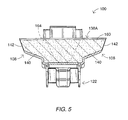
- FIG. 5 is a cross-sectional view of the enclosure assembly of FIG. 1 taken along the line 5 - 5 of FIG. 1 .
- FIG. 6 is a top perspective view of a housing forming a part of the enclosure assembly of FIG. 1 .
- FIG. 7 is a top plan view of the housing of FIG. 6 .
- FIG. 8 is an exploded, top perspective view of a transverse wedge connector and conductors according to embodiments of the present invention.
- FIG. 9 is a top perspective view of a connection formed from the transverse wedge connector and conductors of FIG. 8 .
- FIG. 10 is a side elevational view of the connection of FIG. 9 .
- FIG. 11 is a top perspective view of the connection of FIG. 10 partially mounted in the enclosure assembly of FIG. 1 .
- FIG. 12 is a top perspective view of an enclosed connection assembly including the connection of FIG. 10 and the enclosure assembly of FIG. 1 .
- FIG. 13 is a cross-sectional view of the enclosed connection assembly of FIG. 1 taken along the line 13 - 13 of FIG. 12 .
- FIG. 14 is a cross-sectional view of the enclosed connection assembly of FIG. 1 taken along the line 14 - 14 of FIG. 12 .
- FIG. 15 is a cross-sectional view of the enclosed connection assembly of FIG. 1 taken along the line 15 - 15 of FIG. 12 .
- FIGS. 16 and 17 illustrate methods for forming the enclosure assembly of FIG. 1 .
- FIG. 18 is a top perspective view of an enclosure assembly according to further embodiments of the present invention in an open position.
- FIG. 19 is a top perspective view of a housing forming a part of the enclosure assembly of FIG. 18 .
- FIG. 20 is a bottom perspective view of the housing of FIG. 19 .
- FIG. 21 is a perspective view of an enclosed connection assembly including the enclosure assembly of FIG. 18 .
- FIG. 22 is an enlarged, fragmentary, perspective view of the enclosed connection assembly of FIG. 21 .
- FIG. 23 is a cross-sectional view of the enclosed connection assembly of FIG. 21 taken along the line 23 - 23 of FIG. 21 .
- FIG. 24 is a cross-sectional view of the enclosed connection assembly of FIG. 21 taken along the line 24 - 24 of FIG. 23 .
- FIG. 25 is a cross-sectional, perspective view of the enclosed connection assembly of FIG. 21 taken along the line 23 - 23 of FIG. 21 wherein, for the purposes of illustration, the sealant is not shown.
- first, second, etc. may be used herein to describe various elements, components, regions, layers and/or sections, these elements, components, regions, layers and/or sections should not be limited by these terms. These terms are only used to distinguish one element, component, region, layer or section from another region, layer or section. Thus, a first element, component, region, layer or section discussed below could be termed a second element, component, region, layer or section without departing from the teachings of the present invention.
- spatially relative terms such as “beneath”, “below”, “lower”, “above”, “upper” and the like, may be used herein for ease of description to describe one element or feature's relationship to another element(s) or feature(s) as illustrated in the figures. It will be understood that the spatially relative terms are intended to encompass different orientations of the device in use or operation in addition to the orientation depicted in the figures. For example, if the device in the figures is turned over, elements described as “below” or “beneath” other elements or features would then be oriented “above” the other elements or features. Thus, the exemplary term “below” can encompass both an orientation of above and below. The device may be otherwise oriented (rotated 90° or at other orientations) and the spatially relative descriptors used herein interpreted accordingly.
- a connector system 20 ( FIG. 11 ) according to embodiments of the present invention may be used to form an enclosed and protected connection assembly 24 as shown in FIGS. 12-15 .
- the connector system 20 includes a transverse wedge connector 50 ( FIGS. 8-10 ) and an enclosure assembly 100 ( FIGS. 1-7 ).
- the connector 50 can be used to form a connection 22 ( FIGS. 9 and 10 ) including a pair of elongate conductors 12 , 14 (e.g., electrical power lines) mechanically and electrically coupled by the connector 50 .
- a driver 26 ( FIG. 10 ) may be used to secure the connector 50 on the conductors 12 , 14 .
- the enclosure assembly 100 according to embodiments of the present invention may be installed on and surround the connection 22 to form the enclosed connection assembly 24 .
- the connector 50 includes a first connector member 60 and a second connector member 62 , which together define opposed conductor passages 52 , 54 for receiving the conductors 12 , 14 .
- the connector 50 further includes a clamping mechanism 55 that provides a loading force and secures the connector members 60 , 62 in a desired position.
- the connector members 60 , 62 have the same configuration, shape or profile except as discussed below. Accordingly, it will be appreciated that the description of one connector member 60 , 62 likewise applies to the other.
- Each connector member 60 , 62 includes a generally U-shaped or J-shaped body.
- the body includes opposed leg sections 64 , 66 .
- the leg sections 64 , 66 are joined to by a bend 68 that defines a recess 68 A on its inner side.
- a U-shaped receiver portion or hook portion 70 extends from the distal end of the leg section 64 opposite the bend 68 .
- the hook portion 70 includes a seat surface 72 defining an arcuate, concave (semi-cylindrical) channel 72 A.
- a wedge or abutment portion 74 is provided on the leg section 66 opposite the bend 68 .
- the abutment portion 74 has a flat, planar seat surface 76 .
- a non-threaded bore 80 ( FIG. 8 ) extends through the leg section 66 .
- a non-threaded bore 82 ( FIG. 8 ) extends through the leg section 66 .
- the connector members 60 , 62 are relatively inverted and nested as shown in FIGS. 9 and 10 . That is, the connector members 60 , 62 are rotated 180 degrees with respect to one another so that the abutment portion 74 of the connector member 60 is proximate the hook portion 70 of the connector member 62 and the abutment portion 74 of the connector member 62 is proximate the hook portion 70 of the connector member 60 .
- the adjacent seat surfaces 72 , 76 face one another and define the respective conductor passages 52 , 54 therebetween.
- the channels 72 A of the connector members 60 , 62 define respective channel axes I-I and J-J ( FIG. 9 ).
- a connector longitudinal axis K-K FIGS.
- the axes I-I and J-J are parallel to one another and perpendicular to the axis K-K.
- the axes I-I and J-J define a plane in which the axis K-K lies.
- a bolt 56 and a nut 57 cooperatively serve as a clamping mechanism 55 .
- the bores 80 , 82 are aligned and the shank 56 A of the bolt 56 extends through the bores 80 , 82 .
- the shank 56 A is threaded and threadedly engages the nut 57 but is capable of sliding loosely in the bores 80 , 82 .
- a head 56 B of the bolt 56 is oversized relative to the bore 80 .
- a lock washer 57 A may be positioned between the nut 57 and the connector member 62 .
- Fasteners other that a bolt and nut may be used as a clamping mechanism.
- the bore 82 may be threaded and cooperate with the bolt 56 to serve as the clamping mechanism, in which case the nut 57 may be omitted.
- the clamping mechanism 55 is configured to translate the connector members 60 , 62 relative to one another along a translation axis M-M ( FIGS. 9 and 10 ).
- the translation axis M-M is non-perpendicular to the connector longitudinal axis K-K.
- the axis M-M is transverse to the axis K-K.
- the axis M-M forms an oblique angle B ( FIG. 10 ) with the axis K-K.
- the angle B is between about 40 and 80 degrees.
- the connector members 60 , 62 together have 180 degree rotational symmetry (i.e., are collectively symmetric under a 180 degree rotation or are reverse mirror images of one another). That is, with the exception of the clamping mechanism 55 , the connector 50 is 180 degree rotationally symmetric.
- the connector members 60 , 62 may be formed of any suitable material. According to some embodiments, the connector members 60 , 62 are formed of metal. According to some embodiments, the connector members 60 , 62 are formed of aluminum or steel. According to some embodiments, the connector members 60 , 62 are formed of aluminum alloy 6061 heat treated in T6 condition. The connector members 60 , 62 may be formed using any suitable technique. According to some embodiments, each of the connector members 60 , 62 is unitarily formed. According to some embodiments, the connector members 60 , 62 are extruded and cut. Alternatively or additionally, the connector members 60 , 62 may be stamped (e.g., die-cut), cast and/or machined. Because the connector members 60 , 62 are identically configured, only one configuration needs to be produced.
- the leg section 64 has a thickness that is less than the thickness of the leg section 66 so that the leg section 64 tends to bend between the bend 68 and the hook portion 70 when the connector 50 is loaded against the conductors 12 , 14 .
- the radius of curvature of the hook portion seat surfaces 72 is between about 1 ⁇ 8 and 3 ⁇ 4 inch. According to some embodiments, each of the seat surfaces 72 extends along an arc of between about 120 and 180 degrees.
- each planar abutment portion seat surface 76 is between about 1 and 2 inches.
- the ratio of the length L ( FIG. 8 ) of each channel 72 A to the outer diameter of the conductor 12 , 14 to be received is between about 2 and 25.
- the depth of the channels 72 A is between about 1 ⁇ 8 and 1.2 inches.
- transverse wedge connectors that may be suitable for use in place of the connector 50 are disclosed in U.S. Pat. No. 7,182,653 to Hoxha and U.S. Pat. No. 7,309,263 to Copper et al., the disclosures of which are incorporated herein by reference.
- the sealant-filled enclosure 100 includes a housing 120 and masses of sealant 160 , 170 disposed therein.
- the sealant 160 , 170 may be a gel.
- the housing 100 includes a first shell or cover member 122 and a second shell or cover member 124 joined to one another by a hinge 126 and adapted to move between an open position as shown in FIGS. 1 and 11 and a closed position as shown in FIGS. 12-15 .
- the cover members are not hinged. In the open position, the enclosure assembly 100 can receive the connection 22 and adjacent portions of the conductors 12 , 14 .
- the enclosure assembly 100 In the closed position, the enclosure assembly 100 , including the masses of sealant 160 , 170 , may operate to seal about and protect the connection 22 . In the closed position, the enclosure assembly 100 defines an enclosure cavity 106 ( FIGS. 13 and 15 ) and opposed pairs of ports 108 communicating with the enclosure cavity 106 . The shape or geometry of the enclosure cavity 106 resembles or substantially conforms to that of the connector 50 .
- each cover member 122 , 124 is constructed in generally the same manner, except for the configurations of the latch structures and placement relative to the hinge 126 .
- Each cover member 122 , 124 includes a bottom wall 130 .
- a dome 130 A is defined in the bottom wall 130 .
- Opposed side walls 132 and opposed end walls 134 extend upwardly from the bottom wall 130 .
- Opposed locator ribs 148 extend upwardly from the bottom wall 130 and inwardly from the side walls 132 .
- Opposed pairs of port extensions 140 extend longitudinally from either end of each cover member 122 , 124 .
- Each port extension 140 is terminated by a port wall 142 .
- the port walls 142 may be frangible.
- the port walls 142 may include corrugations comprising a series of fingers joined by relatively thin membranes as shown.
- the upper edges of the walls 132 , 134 form a perimeter edge 138 defining an opening 138 A.
- the walls 130 , 132 , 134 and the port extensions 140 of each cover member 122 , 124 define an overall cover member chamber or cavity 136 and a front opening 130 A communicating with opening 138 A.
- the cavity 136 includes a main cavity portion 136 A and conductor port subchannels 136 B defined within each port extension 140 .
- the cover members 122 , 124 are pivotably joined by the hinge 126 .
- the hinge 126 is a flexible, living hinge.
- a living hinge may allow for unitary formation of the housing 120 , as well as possible cost savings in materials and assembly.
- other hinge configurations may be employed.
- the hinge 126 may be replaced by or supplemented with interlocking pivotally coupled hinge structures and/or a pivot pin.
- the cover members 122 , 124 may be non-hinged.
- Latch structures 144 A, 144 B are located on the respective sidewalls 132 opposite the hinge 126 .
- the latch structures 144 A, 144 B are adapted to cooperate with one another to permanently or releasably secure the housing 120 in the closed position.
- Opposed tie slots 146 are defined in each cover member 122 , 124 .
- the housing 120 may be formed of any suitable material. According to some embodiments, the housing 120 is formed of an electrically insulative material. In some embodiments, the housing 120 is formed of a vacuum formed or molded polymeric material. The housing 120 may be formed of polypropylene, nylon, polyethylene, ABS and/or PMMA. The housing 120 may be formed of a flame retardant material. The housing material may be any color or transparent.
- the sealant 160 may be contained in the cavity 136 of the cover member 122 such that a main sealant portion 162 ( FIG. 1 ) of the sealant is disposed in the main cavity 136 and port sealant portions 166 ( FIG. 1 ) are disposed in the port subchannels 136 B.
- a void 164 ( FIG. 1 ) is defined in the sealant 160 .
- the void 164 is open to the opening 138 A.
- the sealant 160 fully surrounds the remainder of the void 164 so that the void 164 is spaced apart from cover member 122 on all sides except the top side.
- the void extends fully to the bottom wall 130 .
- the sealant 160 fills the cover member cavity 136 to a level near but not fully to the perimeter edge 138 .
- the sealant 160 fills the cover member cavity 136 substantially fully up to the perimeter edge 138 or to any other desired level.
- the void 164 has sloped side walls that taper outwardly in a direction from the bottom wall 130 to the opening 138 A.
- the void 164 is shaped as an inverted frusto-pyramid.
- the void 164 may be of any other suitable shape.
- the sealant 170 may be contained in the cavity 136 of the cover member 124 such that a main sealant portion 172 ( FIG. 1 ) of the sealant is disposed in the main cavity 136 and port sealant portions 176 ( FIG. 1 ) are disposed in the port subchannels 136 B.
- a void 174 is defined in the sealant 170 .
- the void 174 is open to the opening 138 A.
- the sealant 170 fully surrounds the remainder of the void 174 so that the void 174 is spaced apart from cover member 124 on all sides except the top side.
- the void extends fully to the bottom wall 130 .
- the sealant 170 fills the cover members cavity 136 to a level near but not fully to the perimeter edge 138 . In other embodiments, the sealant 170 fills the cover member cavity 136 substantially fully up to the perimeter edge 138 or to any other desired level.
- the void 174 has sloped side walls that taper outwardly in a direction from the bottom wall 130 to the opening 138 A.
- the void 174 is shaped as an inverted frusto-pyramid.
- the void 174 may be of any other suitable shape.
- the sealants 160 , 170 may be any suitable sealants.
- the sealants 160 , 170 are gel sealants.
- gel refers to the category of materials which are solids extended by a fluid extender. The gel may be a substantially dilute system that exhibits no steady state flow.
- a polymer gel may be a cross-linked solution whether linked by chemical bonds or crystallites or some other kind of junction.
- the absence of the steady state flow may be considered to be the definition of the solid-like properties while the substantial dilution may be necessary to give the relatively low modulus of gels.
- the solid nature may be achieved by a continuous network structure formed in the material generally through crosslinking the polymer chains through some kind of junction or the creation of domains of associated substituents of various branch chains of the polymer.
- the crosslinking can be either physical or chemical as long as the crosslink sites may be sustained at the use conditions of the gel.
- Gels for use in this invention may be silicone (organopolysiloxane) gels, such as the fluid-extended systems taught in U.S. Pat. No. 4,634,207 to Debbaut (hereinafter “Debbaut '207”); U.S. Pat. No. 4,680,233 to Camin et al.; U.S. Pat. No. 4,777,063 to Dubrow et al.; and U.S. Pat. No. 5,079,300 to Dubrow et al. (hereinafter “Dubrow '300”), the disclosures of each of which are hereby incorporated herein by reference.
- silicone organopolysiloxane
- silicone gels may be created with nonreactive fluid extenders as in the previously recited patents or with an excess of a reactive liquid, e.g., a vinyl-rich silicone fluid, such that it acts like an extender, as exemplified by the Sylgard® 527 product commercially available from Dow-Corning of Midland, Mich. or as disclosed in U.S. Pat. No. 3,020,260 to Nelson. Because curing is generally involved in the preparation of these gels, they are sometimes referred to as thermosetting gels.
- a reactive liquid e.g., a vinyl-rich silicone fluid
- the gel may be a silicone gel produced from a mixture of divinyl terminated polydimethylsiloxane, tetrakis (dimethylsiloxy)silane, a platinum divinyltetramethyldisiloxane complex, commercially available from United Chemical Technologies, Inc. of Bristol, Pa., polydimethylsiloxane, and 1,3,5,7-tetravinyltetra-methylcyclotetrasiloxane (reaction inhibitor for providing adequate pot life).
- Gels may be used, for example, polyurethane gels as taught in the aforementioned Debbaut '261 and U.S. Pat. No. 5,140,476 to Debbaut (hereinafter “Debbaut '476”) and gels based on styrene-ethylene butylenestyrene (SEBS) or styrene-ethylene propylene-styrene (SEPS) extended with an extender oil of naphthenic or nonaromatic or low aramatic content hydrocarbon oil, as described in U.S. Pat. No. 4,369,284 to Chen; U.S. Pat. No. 4,716,183 to Gamarra et al.; and U.S. Pat. No.
- SEBS styrene-ethylene butylenestyrene
- SEPS styrene-ethylene propylene-styrene
- the SEBS and SEPS gels comprise glassy styrenic microphases interconnected by a fluid-extended elastomeric phase.
- the microphase-separated styrenic domains serve as the junction points in the systems.
- the SEBS and SEPS gels are examples of thermoplastic systems.
- EPDM rubber-based gels as described in U.S. Pat. No. 5,177,143 to Chang et al.
- Yet another class of gels which may be used are based on anhydride-containing polymers, as disclosed in WO 96/23007. These gels reportedly have good thermal resistance.
- the gel may include a variety of additives, including stabilizers and antioxidants such as hindered phenols (e.g., IrganoxTM 1076, commercially available from Ciba-Geigy Corp. of Tarrytown, N.Y.), phosphites (e.g., IrgafosTM 168, commercially available from Ciba-Geigy Corp. of Tarrytown, N.Y.), metal deactivators (e.g., IrganoxTM D1024 from Ciba-Geigy Corp. of Tarrytown, N.Y.), and sulfides (e.g., Cyanox LTDP, commercially available from American Cyanamid Co.
- stabilizers and antioxidants such as hindered phenols (e.g., IrganoxTM 1076, commercially available from Ciba-Geigy Corp. of Tarrytown, N.Y.), phosphites (e.g., Irgaf
- halogenated paraffins e.g., Bromoklor 50, commercially available from Ferro Corp. of Hammond, Ind.
- phosphorous containing organic compounds e.g., Fyrol PCF and Phosflex 390, both commercially available from Akzo Nobel Chemicals Inc. of Dobbs Ferry, N.Y.
- acid scavengers e.g., DHT-4A, commercially available from Kyowa Chemical Industry Co. Ltd through Mitsui & Co. of Cleveland, Ohio, and hydrotalcite.
- suitable additives include colorants, biocides, tackifiers and the like described in “Additives for Plastics, Edition 1” published by D.A.T.A., Inc. and The International Plastics Selector, Inc., San Diego, Calif.
- the hardness, stress relaxation, and tack may be measured using a Texture Technologies Texture Analyzer or like machine, having a load cell to measure force, a 5 gram trigger, and 1 ⁇ 2 inch (6.35 mm) stainless steel probe.
- a Texture Technologies Texture Analyzer or like machine having a load cell to measure force, a 5 gram trigger, and 1 ⁇ 2 inch (6.35 mm) stainless steel probe.
- the probe is forced into the gel at the speed of 0.2 mm/sec to a penetration distance of 4.0 mm.
- the hardness of the gel is the force in grams required to force the probe at that speed to penetrate the gel specified for 4.0 mm. Higher numbers signify harder gels.
- the tack and stress relaxation are read from the stress curve generated by tracing the force versus time curve experienced by the load cell when the penetration speed is 2.0 mm/second and the probe is forced into the gel a penetration distance of about 4.0 mm. The probe is held at 4.0 mm penetration for 1 minute and withdrawn at a speed of 2.00 mm/second.
- the stress relaxation is the ratio of the initial force (F i ) resisting the probe at the pre-set penetration depth minus the force resisting the probe (F f ) after 1 min divided by the initial force F i , expressed as a percentage. That is, percent stress relaxation is equal to
- the stress relaxation is the ratio of the initial force minus the force after 1 minute over the initial force. It may be considered to be a measure of the ability of the gel to relax any induced compression placed on the gel.
- the tack may be considered to be the amount of force in grams resistance on the probe as it is pulled out of the gel when the probe is withdrawn at a speed of 2.0 mm/second from the preset penetration depth.
- Cone penetration (“CP”) values may range from about 70 (10 ⁇ 1 mm) to about 400 (10 ⁇ 1 mm).
- Harder gels may generally have CP values from about 70 (10 ⁇ 1 mm) to about 70 (10 ⁇ 1 mm).
- Softer gels may generally have CP values from about 200 (10 ⁇ 1 mm) to about 400 (10 ⁇ 1 mm), with particularly preferred range of from about 250 (10 ⁇ 1 mm) to about 375 (10 ⁇ 1 mm).
- CP values from about 200 (10 ⁇ 1 mm) to about 400 (10 ⁇ 1 mm)
- particularly preferred range of from about 250 (10 ⁇ 1 mm) to about 375 (10 ⁇ 1 mm).
- a relationship between CP and Voland gram hardness can be developed as proposed in U.S. Pat. No. 4,852,646 to Dittmer et al.
- the gel has a Voland hardness, as measured by a texture analyzer, of between about 5 and 100 grams force.
- the gel may have an elongation, as measured by ASTM D-638, of at least 55%. According to some embodiments, the elongation is of at least 100%.
- the gel may have a stress relaxation of less than 80%.
- the gel may have a tack greater than about 1 gram.
- sealants 160 , 170 are gels as described above, other types of sealants may be employed.
- the sealants 160 , 170 may be silicone grease or hydrocarbon-based grease.
- the enclosure assembly 100 may be formed in the following manner.
- the cover members 122 , 124 and the hinge 126 may be integrally formed.
- the cover members 122 , 124 and the hinge 126 are unitarily molded.
- the entirety of the housing 120 is unitarily molded.
- the housing 120 may be injection molded or vacuum formed, for example.
- the cover members 122 , 124 are separately molded or otherwise formed.
- the sealant 160 , 170 is a material, such as a curable gel, that requires curing, the sealant may be cured in situ.
- the sealants 160 , 170 may be formed as follows. Spacer inserts 8 having the shape and size of the voids 164 , 174 are placed in each cavity 136 .
- the housing 120 is oriented so that the cavities 136 are open upwardly as shown in FIG. 16 .
- Liquid, uncured sealant 163 , 173 is dispensed into the cavities 136 such that it fills the cavities 136 of the cover members 122 , 124 up to the desired level.
- the sealant may then be cured in situ.
- the spacer inserts 8 may be held in place using clips, a jig or the like to properly register the spacer inserts with the cover members 122 , 124 and to prevent the spacer inserts 8 from floating out of the liquid sealant.
- the spacer inserts 8 are then removed as shown in FIG. 17 to provide the voids 164 , 174 in the sealants 160 , 170 .
- the liquid, uncured sealant 163 , 173 may instead be inserted first and then displaced by insertion of the spacer inserts 8 prior to curing the uncured sealant.
- sealant-filled enclosures of the present invention may be formed by other methods. For example, a pre-cured sealant may be introduced into the cavities 136 (e.g., around the spacer inserts 8 ).
- the connector system 20 can be used as follows in accordance with methods of the present invention to form the enclosed connection 24 ( FIGS. 12-15 ).
- the connection 22 is first formed by installing the connector 50 on the conductors 12 , 14 .
- the enclosure assembly 100 is installed over the connection 22 and portions of the conductors 12 , 14 .
- the connector 50 can be used as follows in accordance with methods of the present invention to form the connection 22 ( FIGS. 9 and 10 ).
- the bolt 56 may be initially inserted through the bores 80 , 82 and the nut 57 loosely threaded onto the bolt 56 so that the connector members 60 , 62 can be separated into an open position (e.g., as shown in FIG. 8 ).
- the conductor passages 52 , 54 open sidewardly to permit lateral insertion of the conductors 12 , 14 into the respective passages 102 , 104 .
- the bolt 56 holds the connector members 60 , 62 together and the widths of the connector members 60 , 62 prevent over-rotation about the bolt 56 so that the proper relative orientation between the connector members 60 , 62 can be easily maintained.
- the installer inserts the conductors 12 , 14 into the passages 52 , 54 as shown in FIG. 8 .
- the conductor 14 is a main electrical power line or conductor
- the connector member 62 is first hooked onto the conductor 14 (i.e., the conductor 14 is positioned in the passage 54 ), and the conductor 12 , which may be a tap electrical power line or conductor, is then positioned in the passage 52 .
- the U-shaped hook portions 70 may serve to temporarily retain the conductors 12 , 14 in the passages 52 , 54 .
- the conductors 12 , 14 are aligned in parallel along the connector axis K-K.
- the installer rotates the bolt 56 in any suitable manner to tighten the connector 50 .
- the bolt 56 is rotated using a driver such as the driver 26 ( FIG. 10 ).
- the driver 26 includes a socket 26 A configured to engage and drive the head 56 B and a power tool 26 B to drive the socket 26 A.
- the power tool 26 B is a battery-powered tool.
- the power tool 26 B is a rechargeable battery-powered tool.
- the bolt 56 draws the connector members 60 , 62 together along the translation axis M-M into a nested configuration.
- the respective portions 70 , 74 are thereby driven or translated towards one another along axes N-N parallel to the axis M-M.
- the abutment faces 76 are angled or sloped with respect to the axes N-N so that they present wedge surfaces that increasingly bear against the conductors 12 , 14 as the abutment faces 76 translate inwardly or converge along the axes N-N.
- the conductor passages 52 , 54 are thereby simultaneously reduced about the conductors 12 , 14 .
- the abutment portions 74 are thus driven in a direction transverse to the axes I-I, J-J of the conductors 12 , 14 to clamp the connector members 60 , 62 about the conductors 12 , 14 .
- the engagement between the inner ends of the abutment portions 74 and the inner sides of the respective bends 68 serves as a displacement stop mechanism to limit the final nesting position of the connector members 60 , 62 .
- the facing surfaces of the abutment portions 74 may slide across one another.
- the configuration of the connector 50 including the oblique angle between the axis M-M and the axis K-K may facilitate operation of the clamping mechanism 55 by positioning the bolt head 568 for convenient access with the driver 26 .
- the installer continues to rotate and torque the bolt 56 until the conductors 12 , 14 are engaged by each of the seat surfaces 72 , 76 and loaded thereby as desired.
- the connector 50 may collapse or deform the conductors 12 , 14 in the passages 52 , 54 .
- the seat surfaces 72 , 76 may form an interference fit with the conductors 12 , 14 .
- the clamping mechanism 55 maintains the connector 50 in this clamping position (as shown in FIGS. 9 and 10 ).
- the U-shaped hook portions 70 form end enclosures that prevent endwise pullout of the conductors 12 , 14 from the connector 50 .
- the arrangement of the connector 50 and its clamping mechanism 55 may serve to efficiently and reliably transfer the tensile force from the bolt 56 to the conductors 12 , 14 .
- the seat surfaces 72 , 76 apply a clamping or compression load of at least about 3000 lbs to the conductors 12 , 14 when the connector 50 is in the clamping position.
- the seat surfaces 72 , 76 apply a clamping load in the range of from about 1500 to 7500 lbs.
- the bolt 56 is rotated and the conductors 12 , 14 are loaded such that the connector members 60 , 62 are elastically and plastically deflected.
- the U-shaped hook portions 70 are elastically deflected within the “U” and/or about the bends 68 .
- the leg sections 66 are elastically deflected about the bends 68 .
- this spring bias may serve to compensate for physical and environmental variations over the life of the connection 22 , such as variations caused by heat and cooling, wind, relaxation, etc. In this way, the elastic deflection may help to ensure a consistently strong or adequate connection.
- the enclosure assembly 100 is installed on the connection 22 and the conductors 12 , 14 .
- the enclosure assembly 100 may be held in a fully or partially open position as shown in FIG. 11 and the connection 22 may be inserted between the cover members 122 , 124 .
- the enclosure assembly 100 is then closed by urging one or both of the cover members 122 , 124 to relatively pivot about the hinge 126 into engagement as shown in FIGS. 12-15 , such that the latch structures 144 A, 144 B are made to lock in the closed position.
- the ties 110 may then be inserted through the tie slots 146 and secured to secure the cover members 122 , 124 in the closed position.
- the closed housing 120 defines an enclosure cavity 106 including a main enclosure cavity 107 and contiguous port channels 109 (collectively defined by the port extensions 140 ).
- the connector 50 is received in the voids 164 , 174 ( FIG. 1 ) of the sealants 160 , 170 .
- the connection 22 is encapsulated within the sealant 160 , 170 , and the sealant 160 , 170 and the connection 22 are in turn encapsulated within the housing 120 (i.e., contained within the enclosure cavity 106 ).
- the portions of the conductors 12 , 14 within the connection 22 and extending from the connection 22 and through the port channels 109 to the frangible walls 142 are likewise encapsulated in the sealant 160 , 170 .
- connection 22 is first placed in the cover member 124 of the enclosure assembly 100 (as shown in FIG. 11 ). More particularly, the connector 50 may be placed or seated in the pre-defined void 174 as shown in FIG. 11 such that the connector 50 may be partially encapsulated in the sealant 170 . The cover 122 is then closed on the cover 124 so that the exposed portion of the connector 50 is received in the pre-defined void 164 and so that this portion of the connector 50 is encapsulated in the sealant 160 . It will be appreciated that the order may be reversed so that the connector 50 is instead first placed in the cover member 122 before closing the enclosure assembly 100 .
- the conductors 12 , 14 may break or splay the frangible walls 142 so that the conductors 12 , 14 pass therethrough and are generally surrounded thereby. Because the walls 142 may be angled outwardly, they tend to be splayed outwardly by the conductors 12 , 14 .
- the locator ribs 148 can serve as centering stops to positively locate the connector 50 with respect to the housing 120 . In this manner, the locator ribs can ensure that a desired minimum standoff is provided as needed to provide an effective encapsulation by the sealant 160 , 170 .
- the volumes and configurations of the sealants 160 , 170 are selected to ensure that the connection 22 displaces at least one, and according to some embodiments, both of the sealants 160 , 170 when the enclosure assembly 100 is transitioned from the opened position to the closed position with the connection 22 disposed therein.
- the combined volume of the connector 50 , the portions of the conductors 12 , 14 in the enclosure cavity 106 , and the sealants 160 , 170 is greater than the volume of the enclosure cavity 106 .
- the volume of the enclosure cavity 106 is greater than the combined volume of the sealants 160 , 170 , but the volume of the enclosure cavity 106 not filled with the sealants 160 , 170 is less than the volume of the connection 22 (i.e., the connector 50 and the portions of the conductors 12 , 14 in the enclosure cavity 106 ).
- the combined volume of the voids 164 , 174 is less than or equal to the volume of the connector 50 .
- the sum of the volumes of the voids 164 , 174 is in the range of from about zero to 95 percent of the volume of the connector 50 and, according to some embodiments, in the range of from about 25 to 95 percent of the volume of the connector 50 .
- the closing of the cover members 122 , 124 about the connection 22 forcibly displaces the sealants 160 , 170 about the connector 50 such that the sealants 160 , 170 flow around the connector 50 and, in some cases, into interstices within the connector 50 .
- the sealants 160 , 170 substantially fully encapsulate the connector 50 as illustrated in FIGS. 13-15 .
- the sealants 160 , 170 only partially surround the connector 50 (e.g., in the case where the voids 164 , 174 extend to the bottom walls 130 ).
- the enclosure assembly 100 may ensure that the housing 120 can be closed without requiring undue force, but nonetheless that the sealants 160 , 170 are displaced and forced to flow about the connection 22 and also that the sealants 160 , 170 sufficiently engage with one another at the interface between the cover members 122 , 124 .
- the side walls 132 ( FIG. 3 ), the end walls 134 ( FIG. 4 ) and the port extensions 140 ( FIG. 5 ) may have slopes that tend to cause each sealant 160 , 170 to flow toward the top opening 138 A of its respective cover member 122 , 124 to promote flow of the sealant about the connection 22 and into engagement with the other sealant 160 , 170 .
- substantially all of the sealant 160 , 170 is retained in the housing 120 when the housing 120 is closed about the connection 22 .
- some of the sealant 160 , 170 may be forced out of the enclosure cavity 106 (e.g., through the ports 108 and/or other opening(s)).
- the sealant 160 , 170 engages portions of the conductors 12 , 14 to form seals thereabout.
- the sealant 160 , 170 also forms a sealing block that surrounds the connector 50 , thereby sealing the connector 50 .
- the sealant masses 160 , 170 connect with one another to encapsulate the connector 50 and conductors 12 , 14 .
- the enclosure assembly 100 may be sized and configured to accommodate and seal multiple or a range of sizes of connectors 50 and conductors 12 , 14 .
- the enclosure assembly 100 may provide a number of advantages.
- the enclosure assembly 100 may provide a reliable seal about the connection 22 . This seal may prevent or inhibit the ingress of moisture that would otherwise cause corrosion of the connection 22 .
- the sealant 160 , 170 particularly gel sealant, may accommodate conductors of different sizes within a prescribed range.
- the interfacing sealant masses 160 , 170 and the relationship between the connector or connection volume and the sealant volumes (and the void 164 , 174 volumes, if provided) may ensure that a suitable seal is provided by and between the sealant masses for a broadened range of sizes connections 22 positioned in the enclosure assembly 100 .
- the conductors 12 , 14 and the housing 120 may apply a compressive force to the sealant 160 , 170 as the assembly 100 is transitioned from the open position to the closed position.
- the gel may thereby be elongated and be generally deformed and substantially conform to the outer surfaces of the connector 50 , the conductors 12 , 14 and to the inner surface of the housing 120 . Some shearing of the gel may occur as well. At least some of the gel deformation may be elastic.
- the restoring force in the gel resulting from this elastic deformation generally causes the gel to operate as a spring exerting an outward force between the housing 120 and the connector 50 and the conductors 12 , 14 .
- the compressive loading and restoring force are maintained by the closure of the cover members 122 , 124 .
- the gel sealant 160 , 170 maintains a reliable and long lasting seal between the housing 120 and the connector 50 and the conductors 12 , 14 .
- the elastic memory of and the retained or restoring force in the elongated, elastically deformed gel generally cause the gel to bear against the mating surfaces of the connector 50 , the conductors 12 , 14 and the interior surface of the housing 120 .
- the tack of the gel may provide adhesion between the gel and these surfaces. The gel, even though it is cold-applied, is generally able to flow about the connector 50 , the conductors 12 , 14 and the housing 120 to accommodate their irregular geometries.
- the sealant 160 , 170 is a self-healing or self-amalgamating gel. This characteristic, combined with the aforementioned compressive force between the connector 50 , conductors 12 , 14 and the housing 120 , may allow the sealant 160 , 170 to re-form into a continuous body if the gel is sheared by the insertion of the conductors 12 , 14 into the enclosure assembly 100 . The gel may also re-form if the connector 50 and conductors 12 , 14 are withdrawn from the gel.
- the sealant 160 , 170 may provide a reliable moisture barrier for the conductors 12 , 14 and the connector 50 , even when the enclosure assembly 100 is subjected to extreme temperatures and temperature changes.
- the housing 120 may be made from an abrasion resistant material that resists being punctured by the abrasive forces.
- the gel sealant may also serve to prevent or inhibit corrosion of the connection 22 by depositing a layer of oil from the gel on the exposed surfaces of the connector 50 and conductor portions 12 , 14 in the enclosure cavity 106 . Even if the gel is removed from the connection 22 , the oil may remain to coat the connection surfaces as a barrier to moisture.
- enclosure assemblies according to the present invention may be provided as pre-formed and fully assembled units, with pre-cured gel or other sealant therein as described above, that may be cold applied about a connection to form a seal.
- the housing 120 is integrally and unitarily formed, the housing may be otherwise formed in accordance with some aspects of invention.
- the cover members 122 , 124 and/or the hinge 126 may be separate parts joined together in hinged fashion or otherwise.
- the cover members 122 , 124 may be separate pieces secured together by tie wraps, snaps, latches or the like and/or not hinged.
- enclosures in accordance with the present invention may have components (e.g., cover members, walls, etc.) and cavities or chambers having shapes, configurations and/or sizes different than those shown and described herein.
- the voids 164 , 174 are substantially centered with respect to the cavities 136 . According to some embodiments, the voids may instead be offset.
- the voids 164 , 174 extend all the way to the bottom walls 130 .
- an enclosure assembly 100 as described herein may be formed without the sealant voids 164 , 174 (i.e., the cover members 122 , 124 are solid filled up to a desired level). In this case, portions of the sealants 160 , 170 may be forced out of the enclosure cavity 106 (e.g., through the ports 108 and/or other openings).
- This modified enclosure assembly can be formed in the same manner as described above for the enclosure assembly 100 except that the aforementioned spacer inserts are omitted.
- a housing as disclosed herein may be used to enclose a connection including a transverse wedge connector (e.g., the connection 22 ) without the provision of sealant (e.g., the sealants 160 , 170 ) therein.
- sealant e.g., the sealants 160 , 170
- Such a sealant-free housing may provide touch protection.
- the enclosure assembly 100 and the connector 50 are pre-configured or packaged as a matched kit.
- the enclosure assembly 100 and the connector 50 need not be provided as a kit.
- the enclosure assembly 100 may be retrofitted onto a connector 50 that has been previously installed, even years prior.
- Connectors according to embodiments of the invention may employ more or fewer clamping mechanisms than shown for the exemplary embodiments. According to some embodiments, other types of clamping mechanisms may be employed.
- the methods and connector assemblies in accordance with embodiments of the present invention may provide the advantages of relatively slow displacement tools (including battery-powered tools). As compared to at least some explosive actuated tools, the present methods and connector assemblies may provide improvements in simplicity, safety, speed, reduction in training requirements, environmental impact, ergonomics, and cost savings. Hand and battery operated tools may also be employed in countries, environments and applications where use of explosives is limited.
- the conductors 12 , 14 are power transmission conductors. According to some embodiments, the conductors 12 , 14 are aerial power transmission conductors. According to some embodiments, the conductor 14 is a main line electrical conductor and the conductor 12 is a tap line electrical conductor. According to some embodiments, the conductors 12 , 14 each include a plurality of elongate strands (e.g., helically wound strands). The conductors 12 , 14 may be insulated or uninsulated. According to some embodiments, one of the conductors 12 , 14 may be replaced with a bar, stirrup or the like.
- the conductors 12 , 14 have a diameter of from about 3/16 to 1.5 inches.
- a connector system 20 ′ ( FIGS. 21 , 23 and 24 ) according to further embodiments of the present invention is shown therein.
- the connector system 20 ′ may be used to form an enclosed and protected connection assembly 24 ′ as shown in FIGS. 21 , 23 and 24 .
- the connector system 20 ′ includes a transverse wedge connector 50 ′ ( FIG. 25 ) and an enclosure assembly 200 ( FIG. 18 ).
- the connector 50 ′ can be used to form a connection 22 ′ ( FIG. 23 ) including a pair of elongate conductors 12 , 14 (e.g., electrical power lines) mechanically and electrically coupled by the connector 50 ′.
- the enclosure assembly 100 according to embodiments of the present invention may be installed on and surround the connection 22 to faun the enclosed connection assembly 24 .
- the connector system 20 ′ may be constructed and used as discussed above with regard to the connector system 20 except as discussed below.
- the connector 50 ′ may correspond to the connector 50 except as follows.
- the connector 50 ′ includes a first connector member 60 ′ and a second connector member 62 ′, which together define opposed conductor passages 52 A′, 54 A′ for receiving the conductors 12 , 14 .
- the connector members 60 ′, 62 ′ may differ from the connector members 60 , 62 of the connector 50 in that the connector members 60 ′, 62 ′ also define an additional set of smaller opposed conductor passages 52 B′, 54 B′ when the connector 50 ′ is assembled.
- the connector 50 ′ further includes a clamping mechanism 55 ′ that provides a loading force and secures the connector members 60 ′, 62 ′ in a desired position.
- the clamping mechanism 55 ′ includes a nut 57 ′ and a bolt 56 ′ having a threaded shank 56 A′ and a head 56 B′.
- the shank 56 A′ includes an extended portion 56 C′ extending outwardly from the connector members 60 ′, 62 ′ and the nut 57 ′ a distance U ( FIG. 23 ).
- the sealant-filled enclosure 100 includes a housing 220 and masses of sealant 260 , 270 disposed therein and corresponding to the sealant 160 , 170 .
- the enclosure 200 has a longitudinal axis A-A ( FIG. 21 ).
- the housing 220 includes a first shell or cover member 222 and a second shell or cover member 224 corresponding to the cover members 122 , 124 except as discussed below.
- the cover members 222 , 224 are joined to one another by a hinge 226 and adapted to move between an open position as shown in FIG. 18 and a closed position as shown in FIG. 21 . In other embodiments, the cover members 222 , 224 are not hinged.
- the enclosure assembly 200 can receive the connection 22 ′ and adjacent portions of the conductors 12 , 14 .
- the enclosure assembly 200 including the masses of sealant 260 , 270 , may operate to seal about and protect the connection 22 ′.
- the enclosure assembly 200 defines an enclosure cavity 206 ( FIG. 23 ) and opposed pairs of ports 210 A-D communicating with the enclosure cavity 206 .
- the shape or geometry of the enclosure cavity 206 resembles or substantially conforms to that of the connector 50 ′.
- each cover member 222 , 224 is differently configured from one another with respect to their interior chambers, latch structures and placement relative to the hinge 226 .
- Each cover member 222 , 224 includes a bottom wall 230 .
- Opposed side walls 232 and opposed end walls 234 extend upwardly from the bottom walls 230 .
- Opposed locator ribs 248 extend upwardly from the bottom walls 230 and inwardly from the side walls 232 .
- Opposed pairs of port extensions 240 A-H extend longitudinally from either end of each cover member 222 , 224 .
- Each port extension 240 A-H is terminated by a port wall 242 .
- the port walls 242 may be frangible.
- the port walls 242 may include corrugations comprising a series of fingers joined by relatively thin membranes as shown.
- a dome 230 A is defined in the bottom wall 230 of the cover member 222 .
- the dome 230 A is flanked by shoulders 230 B that together define a channel or trough 230 C in the dome 230 A.
- each cover member 222 , 224 The upper edges of the walls 232 , 234 form a perimeter edge defining an opening.
- the walls 230 , 232 , 234 and the port extensions 240 A-H of each cover member 222 , 224 define an overall cover member chamber or cavity 236 communicating with opening.
- Each cavity 236 includes a main cavity portion 236 A and respective conductor port subchannels 244 A-H defined within each port extension 240 A-H.
- the cover members 222 , 224 are pivotably joined by the hinge 226 .
- the hinge 226 is a flexible, living hinge.
- the cover members 222 , 224 may be non-hinged.
- further integral latch mechanisms as described herein may be provided on the rear side of the housing 220 .
- the housing 220 includes an integral latch system 251 .
- the latch system 251 includes a main latch mechanism 250 , a pair of outer port latch mechanisms 252 , and a pair of opposed inner port latch mechanisms 254 .
- the main latch mechanism 250 includes an outer latch structure or panel 250 A having a catch feature or barb 250 B extending inwardly therefrom.
- the main latch mechanism 250 also includes an inner latch feature, rib or strip 250 C opposite the latch panel 250 A.
- the latch panel 250 A is deflectable and resilient to enable the latch panel 250 A to engage and interlock with the latch strip 250 C as shown in FIGS. 22 and 23 .
- the latch structures 250 A and 250 C are integral with the front sides of the cover members 222 and 224 , respectively.
- Each outer port latch mechanism 252 includes a first latch structure or prong 252 A having a catch feature or barb 252 B extending outwardly therefrom.
- Each outer port latch mechanism 252 also includes a second latch structure or receiver 252 C opposite the latch prong 252 A and having a slot or opening 252 D.
- the latch prong 252 A is deflectable and resilient to enable the latch prong 252 A to engage and interlock with the latch receiver 252 C through the opening 252 D as shown in FIG. 22 .
- the latch structures 252 A and 252 C are integral with the front sides of the port extensions 240 A, 240 E and 240 B, 240 F, respectively.
- each inner port latch mechanism 254 includes a first latch structure or tab 254 A coupled to the cover member 222 by a hinge 254 B (e.g., a living hinge) between the port extensions 240 A and 240 C or 240 E and 240 G and having a slot or hole 254 C therein.
- Each inner port latch mechanism 254 also includes a second latch structure or post 254 D extending from the cover member 224 between the port extensions 240 B and 240 D or 240 F and 240 H and opposite the latch tab 254 A.
- Each post 254 D can have a securing notch 254 E.
- the latch tab 252 A is bendable about the hinge 254 B to enable the latch tab 254 A to engage and interlock with the latch post 254 D, which will extend through the opening 254 C as shown in FIG. 21 .
- the latch structures 254 A and 254 D are integral with the inner sides of the port extensions 240 A, 240 C and 240 E, 240 G, respectively.
- Integral scaffolding or bracing structures 254 F may be provided to support the latch structures 254 A, 254 D and stabilize the port extensions 240 A-H.
- the sealant 260 , 270 may be installed and configured in the cavities of the cover members 222 , 224 as discussed above with regard to the sealants 160 , 170 .
- the sealant 260 may be contained in the cavity 236 of the cover member 222 such that port sealant portions 266 ( FIG. 18 ) are disposed in the port subchannels 244 A, 244 C, 244 E, 244 G ( FIG. 19 ).
- the sealant 270 may be contained in the cavity 236 of the cover member 224 such that port sealant portions 276 ( FIG. 18 ) are disposed in the port subchannels 244 B, 244 D, 244 F, 244 H ( FIG. 19 ).
- Voids 264 , 274 may be provided in one or both of the sealants 260 , 270 .
- the enclosure assembly 200 may be formed in the same manner as discussed above with regard to the enclosure assembly 100 .
- the connector system 20 ′ can be used as follows in accordance with methods of the present invention to form the enclosed connection 24 ′ ( FIGS. 21-24 ).
- the connection 22 ′ is first formed by installing the connector 50 ′ on the conductors 12 , 14 as described above with respect to the connector 50 .
- the enclosure assembly 200 is installed over the connection 22 ′ and portions of the conductors 12 , 14 .
- the enclosure assembly 200 can be installed in substantially the same manner as described above with respect to the connector 50 except as follows.
- connection 22 ′ is installed with the lower part of the connector 50 ′ in the cover member 222 and the shank extended portion 56 C′ extending into the channel 230 C, and with the upper part of the connector 50 ′ and the bolt head 5613 ′ in the cover member 224 .
- the cavities 236 of the cover members 222 , 224 are differently shaped so that the interior cavity 206 collectively defined by the closed cover members 222 , 224 is asymmetric about a plane P-P ( FIG. 23 ).
- the interior cavity 206 thus has a shape that fully receives and substantially conforms to the asymmetric shape of the connector 50 ′ when the connector 50 ′ is positioned in a first orientation with the conductor 12 extending through the conductor passages 214 A and 214 C and the conductor 14 extending through the conductor passages 214 B and 214 D, and the shank extended portion 56 C′ projecting into the cover member 222 as shown in FIGS. 21 , 23 and 24 .
- the shape of the interior cavity 206 prevents the insertion of the connector 50 ′ and full closure of the cover members 222 , 224 when the connector 50 ′ is in a second orientation with the conductor 12 extending through the conductor passages 214 B and 214 D, and the conductor 14 extending through the conductor passages 214 A and 214 C, and the shank extended portion 56 C′ projecting into the cover member 224 .
- plane P-P is defined by the interface between the cover members 222 , 224 (i.e., the mating plane).
- the plane P-P is defined by the central longitudinal axes V-V and W-W ( FIG. 24 ) of the ports 210 A, 210 C and 210 , 210 D, respectively.
- the closed housing 220 defines an enclosure cavity 206 including a main enclosure cavity 207 and contiguous port passages 214 A, 214 B, 214 C and 214 D extending through the conductor tubes 212 A, 212 B, 212 C, and 212 D, respectively, and extending to respective port openings 216 A, 216 B, 216 C and 216 D, respectively.
- connection 22 ′ is encapsulated within the sealant 260 , 270 , and the sealant 260 , 270 and the connection 22 ′ are in turn encapsulated within the housing 220 (i.e., contained within the enclosure cavity 206 ).
- the portions of the conductors 12 , 14 within the connection 22 ′ and extending from the connection 22 ′ and through the port passages 214 A-D to the frangible walls 142 are likewise encapsulated in the sealant 260 , 270 .
- Full closure of the cover members 222 , 224 brings the main latch structures 250 A, 250 C into engagement to interlock and also brings the latch structures 252 A, 252 C of each outer port latch mechanism 252 into engagement to interlock, as shown in FIGS. 21-23 .
- the installer can fold each latch tab 254 A up and over the adjacent latch post 254 D to interlock the latch posts 254 D in the holes 254 C as shown in FIGS. 21 and 25 .
- the expansive bias of the sealant 260 , 270 can assist in maintaining the interlocks of the latch mechanisms 250 , 252 , 254 .
- the conductors 12 , 14 may break or splay the frangible walls 242 so that the conductors 12 , 14 pass therethrough and are generally surrounded thereby. Because the walls 242 may be angled outwardly, they tend to be splayed outwardly by the conductors 12 , 14 .
- the locator ribs 248 can serve as centering stops to positively locate the connector 50 ′ with respect to the housing 220 . In this manner, the locator ribs 248 can ensure that a desired minimum standoff is provided as needed to provide an effective encapsulation by the sealant 260 , 270 and that the conductors 12 , 14 are properly aligned with the conductor ports 210 A-D.
- the connector 50 ′ provides additional versatility in that the conductor passages 52 B′, 54 B′ can be used in place of the conductor passages 52 A′, 54 A′ for smaller diameter conductors.
- the relative positions of the conductors and the bolt shank extended portion 56 C′ will be different.
- the installer can rotate the connection 22 ′ as needed about the longitudinal axis A-A in pivot directions R 1 , R 2 ( FIG. 23 ). Such rotation is accommodated by the elongated dome channel 230 C.
- the enclosure assembly 200 may provide a number of advantages.
- the port latch mechanisms 252 , 254 individually and in combination, can serve to fortify the conductor tubes 212 A-D against deformation that may be induced by deflection of the conductors 12 , 14 , bias from the sealant 260 , 270 under compression, or the like.
- the latch mechanisms 252 , 254 in combination with the main latch mechanism 250 and the hinge 226 can provide a reliable and robust closure.
- the barbs or catches 250 B of the main latch panel 250 A are directed inwardly (i.e., toward the cavity 207 ) and the barbs or catches 252 B of the port latch prongs 252 A are directed outwardly (i.e., away from the cavity 207 ).
- This configuration can provide enhanced security and resistance to unintended release when the enclosure 200 is subjected to deforming loads. More particularly and with reference to FIG. 22 , if the cover member 224 is forced rearwardly (i.e., in a direction Q toward the hinge side) relative to the cover member 222 , relative displacement may tend to cause the catches 250 B to slide off of and release from the latch strip 250 C.
- the latch prongs 252 A will be pushed into tighter engagement with the latch receivers 252 C so that the cover members 222 , 224 remain securely locked closed.
- the cover member 224 is forced forwardly (i.e., in a direction T away from the hinge side) relative to the cover member 222 , relative displacement may tend to cause the catches 252 B to slide off of and release from the latch receivers 252 C.
- the main latch panel 250 A will be pushed into tighter engagement with the latch strip 250 C so that the cover members 222 , 224 remain securely locked closed.
- the integral port latch mechanisms 252 , 254 may also be advantageous in that no loose pieces are needed to secure the housing 220 in the closed position.
- the asymmetric interior cavity 207 can accommodate the irregular shape of the connector 50 ′ while also reducing the amount of sealant required to suitably fill the cover members 222 , 224 .
Abstract
Description
Claims (18)
Priority Applications (5)
| Application Number | Priority Date | Filing Date | Title |
|---|---|---|---|
| US12/502,743 US7845990B2 (en) | 2008-07-31 | 2009-07-14 | Connection enclosure assemblies, connector systems and methods for forming an enclosed connection between conductors |
| AU2009277136A AU2009277136B2 (en) | 2008-07-31 | 2009-07-23 | Connection enclosure assemblies, connector systems and methods for forming an enclosed connection between conductors |
| PCT/US2009/004276 WO2010014178A1 (en) | 2008-07-31 | 2009-07-23 | Connection enclosure assemblies, connector systems and methods for forming an enclosed connection between conductors |
| NZ610359A NZ610359A (en) | 2008-07-31 | 2009-07-23 | Connection enclosure assemblies, connector systems and methods for forming an enclosed connection between conductors |
| NZ591404A NZ591404A (en) | 2008-07-31 | 2009-07-23 | Connection enclosure assemblies, connector systems and methods for forming an enclosed connection between conductors |
Applications Claiming Priority (2)
| Application Number | Priority Date | Filing Date | Title |
|---|---|---|---|
| US12/183,577 US7686661B2 (en) | 2008-07-31 | 2008-07-31 | Connection enclosure assemblies, connector systems and methods for forming an enclosed connection between conductors |
| US12/502,743 US7845990B2 (en) | 2008-07-31 | 2009-07-14 | Connection enclosure assemblies, connector systems and methods for forming an enclosed connection between conductors |
Related Parent Applications (1)
| Application Number | Title | Priority Date | Filing Date |
|---|---|---|---|
| US12/183,577 Continuation-In-Part US7686661B2 (en) | 2008-07-31 | 2008-07-31 | Connection enclosure assemblies, connector systems and methods for forming an enclosed connection between conductors |
Publications (2)
| Publication Number | Publication Date |
|---|---|
| US20100130076A1 US20100130076A1 (en) | 2010-05-27 |
| US7845990B2 true US7845990B2 (en) | 2010-12-07 |
Family
ID=41010480
Family Applications (1)
| Application Number | Title | Priority Date | Filing Date |
|---|---|---|---|
| US12/502,743 Active US7845990B2 (en) | 2008-07-31 | 2009-07-14 | Connection enclosure assemblies, connector systems and methods for forming an enclosed connection between conductors |
Country Status (4)
| Country | Link |
|---|---|
| US (1) | US7845990B2 (en) |
| AU (1) | AU2009277136B2 (en) |
| NZ (2) | NZ610359A (en) |
| WO (1) | WO2010014178A1 (en) |
Cited By (15)
| Publication number | Priority date | Publication date | Assignee | Title |
|---|---|---|---|---|
| WO2013006546A1 (en) | 2011-07-06 | 2013-01-10 | Tyco Electronics Corporation | Customizable power utility connectors and methods and connections including same |
| WO2013046001A1 (en) | 2011-09-27 | 2013-04-04 | Tyco Eletronics Brazil Ltda. | Wedge connector assemblies and methods and connections including same |
| US20130280948A1 (en) * | 2012-04-19 | 2013-10-24 | Hirose Electric Co., Ltd. | Electrical connector |
| US20160135315A1 (en) * | 2013-06-27 | 2016-05-12 | Fibox Oy Ab | Enclosure for electrical installations |
| WO2018208540A1 (en) | 2017-05-09 | 2018-11-15 | Te Connectivity Corporation | Wedge connector assembly and method thereof |
| US10283954B2 (en) * | 2017-07-28 | 2019-05-07 | Nicholas T. Tavare | Connection shield for power distribution networks |
| US20200006869A1 (en) * | 2018-06-28 | 2020-01-02 | Te Connectivity Corporation | Connection enclosure assemblies, connector systems and methods for forming an enclosed connection between conductors |
| WO2020100030A1 (en) | 2018-11-13 | 2020-05-22 | TE Connectivity Services Gmbh | Wedge connector assemblies and methods and connections including same |
| US10680353B2 (en) | 2017-05-09 | 2020-06-09 | TE Connectivity Services Gmbh | Wedge connector assemblies and methods and connections including same |
| US10957994B2 (en) | 2017-05-26 | 2021-03-23 | Tyco Electronics Canada Ulc | Wedge connector assemblies and methods and connections including same |
| US10996414B1 (en) | 2020-03-23 | 2021-05-04 | Afl Telecommunications Llc | Butt closures and bases therefor |
| US11152739B2 (en) * | 2019-11-05 | 2021-10-19 | Centurylink Intellectual Property Llc | Connector protective KAP |
| US11329401B2 (en) | 2019-02-20 | 2022-05-10 | Tyco Electronics Canada Ulc | Electrical connection bails and stirrup systems and methods including same |
| US11431114B2 (en) * | 2020-02-14 | 2022-08-30 | Te Connectivity Solutions Gmbh | Enclosed connection systems for forming an enclosed connection between conductors, and methods including same |
| US11561354B2 (en) | 2018-05-09 | 2023-01-24 | Afl Telecommunications Llc | Butt closures and bases therefor |
Families Citing this family (8)
| Publication number | Priority date | Publication date | Assignee | Title |
|---|---|---|---|---|
| US9186175B2 (en) | 2004-10-28 | 2015-11-17 | Nico Corporation | Surgical access assembly and method of using same |
| US9161820B2 (en) * | 2004-10-28 | 2015-10-20 | Nico Corporation | Surgical access assembly and method of using same |
| US20120021658A1 (en) * | 2010-07-22 | 2012-01-26 | Tyco Electronics Corporation | Electrical connector for power conductors |
| DE102012212274B4 (en) * | 2012-07-13 | 2018-06-07 | Te Connectivity Germany Gmbh | Electric plug with seal and method of making the electrical connector |
| US9627793B2 (en) | 2014-03-05 | 2017-04-18 | Standard Cable USA, Inc. | Insulating electrical plugs and method of manufacture |
| US9744703B2 (en) | 2014-03-05 | 2017-08-29 | Standard Cable USA, Inc. | Method of manufacture insulating electrical plugs |
| US9142911B1 (en) * | 2014-03-05 | 2015-09-22 | Standard Cable USA, Inc. | Insulating electrical plugs and method of manufacture |
| JP6466983B2 (en) * | 2017-03-22 | 2019-02-06 | 京セラ株式会社 | connector |
Citations (14)
| Publication number | Priority date | Publication date | Assignee | Title |
|---|---|---|---|---|
| US3112148A (en) | 1962-01-12 | 1963-11-26 | Jasper Blackburn Corp | Protective sheath for an electric connector |
| US3147338A (en) | 1961-08-15 | 1964-09-01 | Harold N Ekvall | Longitudinally divided hinged insulating connector covers |
| US3715459A (en) | 1971-07-15 | 1973-02-06 | Amp Inc | Cable coupling covering and moisture barrier |
| US5347084A (en) | 1991-06-07 | 1994-09-13 | Raychem Corporation | Hinged gel-filled security and environmental protection device |
| US5397859A (en) | 1993-12-10 | 1995-03-14 | The Whitaker Corporation | Enclosure with sealant for spliced coaxial cables |
| US5594210A (en) | 1994-09-28 | 1997-01-14 | Yazaki Corporation | Waterproof protective cover |
| US5763835A (en) | 1995-11-01 | 1998-06-09 | Raychem Corporation | Gel-filled closure |
| US6169250B1 (en) | 1999-04-29 | 2001-01-02 | 3M Innovative Properties Company | Low voltage re-enterable splice enclosure |
| US6333463B1 (en) | 2000-11-17 | 2001-12-25 | Tyco Electronics Corporation | Wire separators having sealant material reservoirs and cable splice closures employing such separators |
| US7138580B2 (en) | 2005-04-25 | 2006-11-21 | Fci Americas Technology, Inc. | Protective cover for fastened electrical connectors |
| US7182653B1 (en) | 2006-04-21 | 2007-02-27 | Tyco Electronics Corporation | Connector assemblies and methods for forming a connection between cables |
| US20070270046A1 (en) * | 2006-05-18 | 2007-11-22 | Tyco Electronics Corporation | Combination wedge tap connector |
| US20080050987A1 (en) * | 2006-05-18 | 2008-02-28 | Tyco Electronics Corporation | Stirrup-Type Power Utility Electrical Connector Assemblies |
| US7432445B2 (en) | 2006-12-18 | 2008-10-07 | Ford Global Technologies, Llc | Wire inline T tap/splice |
-
2009
- 2009-07-14 US US12/502,743 patent/US7845990B2/en active Active
- 2009-07-23 NZ NZ610359A patent/NZ610359A/en not_active IP Right Cessation
- 2009-07-23 AU AU2009277136A patent/AU2009277136B2/en not_active Ceased
- 2009-07-23 WO PCT/US2009/004276 patent/WO2010014178A1/en active Application Filing
- 2009-07-23 NZ NZ591404A patent/NZ591404A/en not_active IP Right Cessation
Patent Citations (17)
| Publication number | Priority date | Publication date | Assignee | Title |
|---|---|---|---|---|
| US3147338A (en) | 1961-08-15 | 1964-09-01 | Harold N Ekvall | Longitudinally divided hinged insulating connector covers |
| US3112148A (en) | 1962-01-12 | 1963-11-26 | Jasper Blackburn Corp | Protective sheath for an electric connector |
| US3715459A (en) | 1971-07-15 | 1973-02-06 | Amp Inc | Cable coupling covering and moisture barrier |
| US5347084A (en) | 1991-06-07 | 1994-09-13 | Raychem Corporation | Hinged gel-filled security and environmental protection device |
| US5397859A (en) | 1993-12-10 | 1995-03-14 | The Whitaker Corporation | Enclosure with sealant for spliced coaxial cables |
| US5561269A (en) | 1993-12-10 | 1996-10-01 | The Whitaker Corporation | Enclosure for spliced coaxial cables |
| US5594210A (en) | 1994-09-28 | 1997-01-14 | Yazaki Corporation | Waterproof protective cover |
| US5763835A (en) | 1995-11-01 | 1998-06-09 | Raychem Corporation | Gel-filled closure |
| US6169250B1 (en) | 1999-04-29 | 2001-01-02 | 3M Innovative Properties Company | Low voltage re-enterable splice enclosure |
| US6333463B1 (en) | 2000-11-17 | 2001-12-25 | Tyco Electronics Corporation | Wire separators having sealant material reservoirs and cable splice closures employing such separators |
| US7138580B2 (en) | 2005-04-25 | 2006-11-21 | Fci Americas Technology, Inc. | Protective cover for fastened electrical connectors |
| US7341479B2 (en) | 2005-04-25 | 2008-03-11 | Fci Americas Technology, Inc. | Protective cover for fastened electrical connectors |
| US7182653B1 (en) | 2006-04-21 | 2007-02-27 | Tyco Electronics Corporation | Connector assemblies and methods for forming a connection between cables |
| US20070270046A1 (en) * | 2006-05-18 | 2007-11-22 | Tyco Electronics Corporation | Combination wedge tap connector |
| US7309263B2 (en) | 2006-05-18 | 2007-12-18 | Tyco Electronics Corporation | Combination wedge tap connector |
| US20080050987A1 (en) * | 2006-05-18 | 2008-02-28 | Tyco Electronics Corporation | Stirrup-Type Power Utility Electrical Connector Assemblies |
| US7432445B2 (en) | 2006-12-18 | 2008-10-07 | Ford Global Technologies, Llc | Wire inline T tap/splice |
Non-Patent Citations (1)
| Title |
|---|
| Notification of Transmittal of the International Search Report and the Written Opinion of the International Searching Authority, or the Declaration for PCT Application No. PCT/US2009/004276, mailed Oct. 11, 2009. |
Cited By (25)
| Publication number | Priority date | Publication date | Assignee | Title |
|---|---|---|---|---|
| US20130012075A1 (en) * | 2011-07-06 | 2013-01-10 | Tyco Electronics Corporation | Customizable power utility connectors and methods and connections including same |
| US8469721B2 (en) * | 2011-07-06 | 2013-06-25 | Tyco Electronics Corporation | Customizable power utility connectors and methods and connections including same |
| WO2013006546A1 (en) | 2011-07-06 | 2013-01-10 | Tyco Electronics Corporation | Customizable power utility connectors and methods and connections including same |
| US8684774B1 (en) | 2011-09-27 | 2014-04-01 | Tyco Electronics Brasil Ltda | Wedge connector assemblies and methods and connections including same |
| WO2013046001A1 (en) | 2011-09-27 | 2013-04-04 | Tyco Eletronics Brazil Ltda. | Wedge connector assemblies and methods and connections including same |
| US8608517B2 (en) | 2011-09-27 | 2013-12-17 | Tyco Electronics Brasil Ltda | Wedge connector assemblies and methods and connections including same |
| US20130280948A1 (en) * | 2012-04-19 | 2013-10-24 | Hirose Electric Co., Ltd. | Electrical connector |
| US9184535B2 (en) * | 2012-04-19 | 2015-11-10 | Hirose Electric Co., Ltd. | Electrical connector |
| US20160135315A1 (en) * | 2013-06-27 | 2016-05-12 | Fibox Oy Ab | Enclosure for electrical installations |
| US9723738B2 (en) * | 2013-06-27 | 2017-08-01 | Fibox Oy Ab | Enclosure for electrical installations |
| WO2018208540A1 (en) | 2017-05-09 | 2018-11-15 | Te Connectivity Corporation | Wedge connector assembly and method thereof |
| US10594054B2 (en) | 2017-05-09 | 2020-03-17 | Tyco Electronics Canada Ulc | Wedge connector assemblies and methods and connections including same |
| US10680353B2 (en) | 2017-05-09 | 2020-06-09 | TE Connectivity Services Gmbh | Wedge connector assemblies and methods and connections including same |
| US10957994B2 (en) | 2017-05-26 | 2021-03-23 | Tyco Electronics Canada Ulc | Wedge connector assemblies and methods and connections including same |
| US10283954B2 (en) * | 2017-07-28 | 2019-05-07 | Nicholas T. Tavare | Connection shield for power distribution networks |
| US11561354B2 (en) | 2018-05-09 | 2023-01-24 | Afl Telecommunications Llc | Butt closures and bases therefor |
| US20200006869A1 (en) * | 2018-06-28 | 2020-01-02 | Te Connectivity Corporation | Connection enclosure assemblies, connector systems and methods for forming an enclosed connection between conductors |
| US10840615B2 (en) * | 2018-06-28 | 2020-11-17 | Te Connectivity Corporation | Connection enclosure assemblies, connector systems and methods for forming an enclosed connection between conductors |
| US11121480B2 (en) | 2018-06-28 | 2021-09-14 | Te Connectivity Corporation | Connection enclosure assemblies, connector systems and methods for forming an enclosed connection between conductors |
| WO2020100030A1 (en) | 2018-11-13 | 2020-05-22 | TE Connectivity Services Gmbh | Wedge connector assemblies and methods and connections including same |
| US11329401B2 (en) | 2019-02-20 | 2022-05-10 | Tyco Electronics Canada Ulc | Electrical connection bails and stirrup systems and methods including same |
| US11152739B2 (en) * | 2019-11-05 | 2021-10-19 | Centurylink Intellectual Property Llc | Connector protective KAP |
| US11431114B2 (en) * | 2020-02-14 | 2022-08-30 | Te Connectivity Solutions Gmbh | Enclosed connection systems for forming an enclosed connection between conductors, and methods including same |
| US10996414B1 (en) | 2020-03-23 | 2021-05-04 | Afl Telecommunications Llc | Butt closures and bases therefor |
| US11500170B2 (en) | 2020-03-23 | 2022-11-15 | Afl Telecommunications Llc | Butt closures and bases therefor |
Also Published As
| Publication number | Publication date |
|---|---|
| NZ610359A (en) | 2014-11-28 |
| WO2010014178A1 (en) | 2010-02-04 |
| US20100130076A1 (en) | 2010-05-27 |
| AU2009277136B2 (en) | 2016-03-10 |
| NZ591404A (en) | 2013-09-27 |
| AU2009277136A1 (en) | 2010-02-04 |
Similar Documents
| Publication | Publication Date | Title |
|---|---|---|
| US7845990B2 (en) | Connection enclosure assemblies, connector systems and methods for forming an enclosed connection between conductors | |
| US7686661B2 (en) | Connection enclosure assemblies, connector systems and methods for forming an enclosed connection between conductors | |
| US11121480B2 (en) | Connection enclosure assemblies, connector systems and methods for forming an enclosed connection between conductors | |
| US9059579B2 (en) | Sealant-filled enclosures and methods for environmentally protecting a connection | |
| CA2736059C (en) | Electrical connection protector kit and method for using the same | |
| US20040157488A1 (en) | Electrical connectors and methods for using the same | |
| US20090023321A1 (en) | Electrical connector assemblies and methods for forming and using the same | |
| US7201596B1 (en) | Electrical connector systems, plug systems and methods for using the same | |
| US8178783B2 (en) | Sealant-filled enclosures and methods for environmentally protecting a connection | |
| US6333463B1 (en) | Wire separators having sealant material reservoirs and cable splice closures employing such separators | |
| KR101634206B1 (en) | Sealant-filled enclosures and methods for environmentally protecting a connection | |
| US7109423B1 (en) | Electrical connection protector kits, insert assemblies and methods for using the same | |
| US11431114B2 (en) | Enclosed connection systems for forming an enclosed connection between conductors, and methods including same | |
| CA2400029C (en) | Electrical connection protector kit and method for using the same | |
| AU2001249671A1 (en) | Electrical connection protector kit and method for using the same |
Legal Events
| Date | Code | Title | Description |
|---|---|---|---|
| AS | Assignment |
Owner name: TYCO ELECTRONICS CORPORATION, PENNSYLVANIA Free format text: ASSIGNMENT OF ASSIGNORS INTEREST;ASSIGNORS:SHRUM, MAIGAN G.;MARKS, JIMMY E.;PULLIUM, GEORGE W., III;AND OTHERS;SIGNING DATES FROM 20100120 TO 20100329;REEL/FRAME:024338/0510 |
|
| STCF | Information on status: patent grant |
Free format text: PATENTED CASE |
|
| FPAY | Fee payment |
Year of fee payment: 4 |
|
| AS | Assignment |
Owner name: TE CONNECTIVITY CORPORATION, PENNSYLVANIA Free format text: CHANGE OF NAME;ASSIGNOR:TYCO ELECTRONICS CORPORATION;REEL/FRAME:041350/0085 Effective date: 20170101 |
|
| MAFP | Maintenance fee payment |
Free format text: PAYMENT OF MAINTENANCE FEE, 8TH YEAR, LARGE ENTITY (ORIGINAL EVENT CODE: M1552) Year of fee payment: 8 |
|
| AS | Assignment |
Owner name: TE CONNECTIVITY SERVICES GMBH, SWITZERLAND Free format text: CHANGE OF ADDRESS;ASSIGNOR:TE CONNECTIVITY SERVICES GMBH;REEL/FRAME:056514/0015 Effective date: 20191101 Owner name: TE CONNECTIVITY SERVICES GMBH, SWITZERLAND Free format text: ASSIGNMENT OF ASSIGNORS INTEREST;ASSIGNOR:TE CONNECTIVITY CORPORATION;REEL/FRAME:056514/0048 Effective date: 20180928 |
|
| AS | Assignment |
Owner name: TE CONNECTIVITY SOLUTIONS GMBH, SWITZERLAND Free format text: MERGER;ASSIGNOR:TE CONNECTIVITY SERVICES GMBH;REEL/FRAME:060885/0482 Effective date: 20220301 |
|
| MAFP | Maintenance fee payment |
Free format text: PAYMENT OF MAINTENANCE FEE, 12TH YEAR, LARGE ENTITY (ORIGINAL EVENT CODE: M1553); ENTITY STATUS OF PATENT OWNER: LARGE ENTITY Year of fee payment: 12 |