US7846176B2 - Embolic protection system - Google Patents
Embolic protection system Download PDFInfo
- Publication number
- US7846176B2 US7846176B2 US11/669,460 US66946007A US7846176B2 US 7846176 B2 US7846176 B2 US 7846176B2 US 66946007 A US66946007 A US 66946007A US 7846176 B2 US7846176 B2 US 7846176B2
- Authority
- US
- United States
- Prior art keywords
- embolic protection
- filter
- catheter
- guidewire
- filter element
- Prior art date
- Legal status (The legal status is an assumption and is not a legal conclusion. Google has not performed a legal analysis and makes no representation as to the accuracy of the status listed.)
- Expired - Fee Related, expires
Links
Images


Classifications
-
- A—HUMAN NECESSITIES
- A61—MEDICAL OR VETERINARY SCIENCE; HYGIENE
- A61F—FILTERS IMPLANTABLE INTO BLOOD VESSELS; PROSTHESES; DEVICES PROVIDING PATENCY TO, OR PREVENTING COLLAPSING OF, TUBULAR STRUCTURES OF THE BODY, e.g. STENTS; ORTHOPAEDIC, NURSING OR CONTRACEPTIVE DEVICES; FOMENTATION; TREATMENT OR PROTECTION OF EYES OR EARS; BANDAGES, DRESSINGS OR ABSORBENT PADS; FIRST-AID KITS
- A61F2/00—Filters implantable into blood vessels; Prostheses, i.e. artificial substitutes or replacements for parts of the body; Appliances for connecting them with the body; Devices providing patency to, or preventing collapsing of, tubular structures of the body, e.g. stents
- A61F2/0095—Packages or dispensers for prostheses or other implants
-
- A—HUMAN NECESSITIES
- A61—MEDICAL OR VETERINARY SCIENCE; HYGIENE
- A61F—FILTERS IMPLANTABLE INTO BLOOD VESSELS; PROSTHESES; DEVICES PROVIDING PATENCY TO, OR PREVENTING COLLAPSING OF, TUBULAR STRUCTURES OF THE BODY, e.g. STENTS; ORTHOPAEDIC, NURSING OR CONTRACEPTIVE DEVICES; FOMENTATION; TREATMENT OR PROTECTION OF EYES OR EARS; BANDAGES, DRESSINGS OR ABSORBENT PADS; FIRST-AID KITS
- A61F2/00—Filters implantable into blood vessels; Prostheses, i.e. artificial substitutes or replacements for parts of the body; Appliances for connecting them with the body; Devices providing patency to, or preventing collapsing of, tubular structures of the body, e.g. stents
- A61F2/01—Filters implantable into blood vessels
- A61F2/011—Instruments for their placement or removal
-
- A—HUMAN NECESSITIES
- A61—MEDICAL OR VETERINARY SCIENCE; HYGIENE
- A61B—DIAGNOSIS; SURGERY; IDENTIFICATION
- A61B17/00—Surgical instruments, devices or methods, e.g. tourniquets
- A61B17/22—Implements for squeezing-off ulcers or the like on the inside of inner organs of the body; Implements for scraping-out cavities of body organs, e.g. bones; Calculus removers; Calculus smashing apparatus; Apparatus for removing obstructions in blood vessels, not otherwise provided for
- A61B17/221—Gripping devices in the form of loops or baskets for gripping calculi or similar types of obstructions
-
- A—HUMAN NECESSITIES
- A61—MEDICAL OR VETERINARY SCIENCE; HYGIENE
- A61F—FILTERS IMPLANTABLE INTO BLOOD VESSELS; PROSTHESES; DEVICES PROVIDING PATENCY TO, OR PREVENTING COLLAPSING OF, TUBULAR STRUCTURES OF THE BODY, e.g. STENTS; ORTHOPAEDIC, NURSING OR CONTRACEPTIVE DEVICES; FOMENTATION; TREATMENT OR PROTECTION OF EYES OR EARS; BANDAGES, DRESSINGS OR ABSORBENT PADS; FIRST-AID KITS
- A61F2/00—Filters implantable into blood vessels; Prostheses, i.e. artificial substitutes or replacements for parts of the body; Appliances for connecting them with the body; Devices providing patency to, or preventing collapsing of, tubular structures of the body, e.g. stents
- A61F2/01—Filters implantable into blood vessels
- A61F2/013—Distal protection devices, i.e. devices placed distally in combination with another endovascular procedure, e.g. angioplasty or stenting
-
- A—HUMAN NECESSITIES
- A61—MEDICAL OR VETERINARY SCIENCE; HYGIENE
- A61F—FILTERS IMPLANTABLE INTO BLOOD VESSELS; PROSTHESES; DEVICES PROVIDING PATENCY TO, OR PREVENTING COLLAPSING OF, TUBULAR STRUCTURES OF THE BODY, e.g. STENTS; ORTHOPAEDIC, NURSING OR CONTRACEPTIVE DEVICES; FOMENTATION; TREATMENT OR PROTECTION OF EYES OR EARS; BANDAGES, DRESSINGS OR ABSORBENT PADS; FIRST-AID KITS
- A61F2/00—Filters implantable into blood vessels; Prostheses, i.e. artificial substitutes or replacements for parts of the body; Appliances for connecting them with the body; Devices providing patency to, or preventing collapsing of, tubular structures of the body, e.g. stents
- A61F2/95—Instruments specially adapted for placement or removal of stents or stent-grafts
- A61F2/9522—Means for mounting a stent or stent-graft onto or into a placement instrument
-
- A—HUMAN NECESSITIES
- A61—MEDICAL OR VETERINARY SCIENCE; HYGIENE
- A61F—FILTERS IMPLANTABLE INTO BLOOD VESSELS; PROSTHESES; DEVICES PROVIDING PATENCY TO, OR PREVENTING COLLAPSING OF, TUBULAR STRUCTURES OF THE BODY, e.g. STENTS; ORTHOPAEDIC, NURSING OR CONTRACEPTIVE DEVICES; FOMENTATION; TREATMENT OR PROTECTION OF EYES OR EARS; BANDAGES, DRESSINGS OR ABSORBENT PADS; FIRST-AID KITS
- A61F2/00—Filters implantable into blood vessels; Prostheses, i.e. artificial substitutes or replacements for parts of the body; Appliances for connecting them with the body; Devices providing patency to, or preventing collapsing of, tubular structures of the body, e.g. stents
- A61F2/01—Filters implantable into blood vessels
- A61F2/013—Distal protection devices, i.e. devices placed distally in combination with another endovascular procedure, e.g. angioplasty or stenting
- A61F2002/015—Stop means therefor
-
- A—HUMAN NECESSITIES
- A61—MEDICAL OR VETERINARY SCIENCE; HYGIENE
- A61F—FILTERS IMPLANTABLE INTO BLOOD VESSELS; PROSTHESES; DEVICES PROVIDING PATENCY TO, OR PREVENTING COLLAPSING OF, TUBULAR STRUCTURES OF THE BODY, e.g. STENTS; ORTHOPAEDIC, NURSING OR CONTRACEPTIVE DEVICES; FOMENTATION; TREATMENT OR PROTECTION OF EYES OR EARS; BANDAGES, DRESSINGS OR ABSORBENT PADS; FIRST-AID KITS
- A61F2/00—Filters implantable into blood vessels; Prostheses, i.e. artificial substitutes or replacements for parts of the body; Appliances for connecting them with the body; Devices providing patency to, or preventing collapsing of, tubular structures of the body, e.g. stents
- A61F2/01—Filters implantable into blood vessels
- A61F2002/018—Filters implantable into blood vessels made from tubes or sheets of material, e.g. by etching or laser-cutting
-
- A—HUMAN NECESSITIES
- A61—MEDICAL OR VETERINARY SCIENCE; HYGIENE
- A61F—FILTERS IMPLANTABLE INTO BLOOD VESSELS; PROSTHESES; DEVICES PROVIDING PATENCY TO, OR PREVENTING COLLAPSING OF, TUBULAR STRUCTURES OF THE BODY, e.g. STENTS; ORTHOPAEDIC, NURSING OR CONTRACEPTIVE DEVICES; FOMENTATION; TREATMENT OR PROTECTION OF EYES OR EARS; BANDAGES, DRESSINGS OR ABSORBENT PADS; FIRST-AID KITS
- A61F2230/00—Geometry of prostheses classified in groups A61F2/00 - A61F2/26 or A61F2/82 or A61F9/00 or A61F11/00 or subgroups thereof
- A61F2230/0002—Two-dimensional shapes, e.g. cross-sections
- A61F2230/0004—Rounded shapes, e.g. with rounded corners
- A61F2230/0006—Rounded shapes, e.g. with rounded corners circular
-
- A—HUMAN NECESSITIES
- A61—MEDICAL OR VETERINARY SCIENCE; HYGIENE
- A61F—FILTERS IMPLANTABLE INTO BLOOD VESSELS; PROSTHESES; DEVICES PROVIDING PATENCY TO, OR PREVENTING COLLAPSING OF, TUBULAR STRUCTURES OF THE BODY, e.g. STENTS; ORTHOPAEDIC, NURSING OR CONTRACEPTIVE DEVICES; FOMENTATION; TREATMENT OR PROTECTION OF EYES OR EARS; BANDAGES, DRESSINGS OR ABSORBENT PADS; FIRST-AID KITS
- A61F2230/00—Geometry of prostheses classified in groups A61F2/00 - A61F2/26 or A61F2/82 or A61F9/00 or A61F11/00 or subgroups thereof
- A61F2230/0063—Three-dimensional shapes
- A61F2230/0067—Three-dimensional shapes conical
Definitions
- This invention relates to a transvascular embolic protection system for safely capturing and retaining embolic material released during an interventional procedure while maintaining blood flow.
- WO-A-99/23976 describes various embolic protection systems of this type.
- WO-A-99/51167 and WO-A-99/51166 describe delivery catheters for delivery of an embolic protection filter to a desired site in the vascular system.
- Various embolic filters are described in WO-A-00/67668, WO-A-00/67669 WO-A-00/67670 and WO-A00/67671.
- a retrieval catheter for use with such embolic protection systems is described in WO-A-01/12082.
- an embolic protection system comprising:
- the guidewire path is in isolation from the embolic material captured within the filter body.
- the tubular guidewire path is defined by a tubular sleeve.
- the tubular sleeve extends from the proximal end to the distal end of the filter.
- the guidewire path is a tubular guidewire path.
- the engagement elements comprise a guidewire engagement element on the guidewire and a filter engagement element on the filter, the engagement elements co-operating to provide selective engagement and positioning of the filter with respect to the guidewire.
- the engagement element of the guidewire comprises a guidewire abutment on the guidewire.
- the guidewire abutment may be located at the distal end of the guidewire.
- the guidewire abutment may be located proximal of the distal and of the guidewire.
- the engagement element of the filter comprises a filter abutment on the filter.
- the filter abutment may be a distal abutment on the filter.
- the filter abutment may be a proximal abutment on the filter.
- tubular guidewire path is defined by a sleeve and the filter abutment is provided by the sleeve.
- the engagement elements comprise releasable locking elements.
- the releasable locking elements comprise a taper lock.
- the guidewire engagement element comprises a locking ring on the guidewire and the filter engagement element comprises a tapered surface of the filter, the locking ring having a tapered surface which is engageable with the tapered surface of the filter to lock the filter to the guidewire.
- the locking ring is a split ring.
- the embolic protection system includes a tube advanceable over the guidewire, the locking ring being located between a distal end of the tube and the filter for retrieval of the filter.
- the releasable locking means includes a tether engageable with the filter for retrieving the filter into the retrieval catheter.
- the embolic protection system comprises deployment means for moving the collapsed filter relative to the distal end of the delivery catheter.
- deployment means comprises a tube which is advanceable over the guidewire for engagement with the proximal end of the filter, the tube being movable longitudinally relative to the delivery catheter for deployment of the filter from the distal end of the delivery catheter.
- the embolic protection system includes loading means for loading the filter into the delivery catheter.
- the loading means comprises a funnel having a narrowed portion disposed at the distal end of the delivery catheter and an enlarged portion for receiving a proximal portion of the filter in the expanded configuration, the filter being progressively collapsed as it is moved through the funnel for loading into the delivery catheter.
- the embolic protection system includes engagement means for engaging the filter within the retrieval catheter.
- the engagement means comprises a frictional engagement between the filter body and an internal surface of the distal end of the retrieval catheter.
- the engagement means comprises projections on the inner surface of the retrieval catheter adjacent the distal end thereof.
- the delivery catheter includes an elongate slot disposed in a first sidewall thereof at a first distal location which is spaced a relatively longer distance from the proximal end of the delivery catheter than from the distal end of the delivery catheter, and wherein the inner deployment catheter includes an aperture disposed in a second sidewall thereof at a second distal location which substantially corresponds with said first distal location for said elongate slot, thereby permitting cooperative movement of said filter with respect to said guidewire and associated delivery and deployment catheters for selective deployment of the filter while facilitating the rapid exchange of said catheter and filer assembly over a guidewire without the utilization of exchange wires or extension wires.
- the embolic protection filter may comprise a collapsible filter body, the proximal inlet end of the filter body having one or more inlet openings sized to allow blood and embolic material enter the filter body, the distal outlet end of the filter body having a plurality of outlet openings sized to allow through passage of blood but to retain undesired embolic material within the filter body.
- the filter comprises a collapsible filter support frame having a proximal end and a distal end, the filter support frame being movable between a collapsed position for movement during delivery through the vascular system and an extended outwardly projecting position to support the filter body in an expanded position thereby urging the filter body into apposition with the vasculature upon deployment.
- the embolic protection system comprises a guide olive provided at the distal end of the filter body.
- the embolic protection system comprises an inner elongate sleeve to which the filter body and the filter support frame are mounted, the sleeve having a proximal end and a distal end, the guide olive extending distally of the sleeve distal end.
- the proximal end of the filter support frame and the inlet end of the filter body are preferably attached to the proximal end of the sleeve.
- the guide olive may be integral with the filter body.
- the guide olive tapers distally inwardly.
- the invention provides a method for the capture and removal of embolic material from a blood vessel during an interventional procedure comprising the steps of:
- the method comprises the step of providing a catheter over the guidewire after withdrawal of the retrieval catheter.
- the method includes the step of moving the guidewire after withdrawal of the retrieval catheter and the collapsed filter from the vasculature to re-position the guidewire in the vasculature.
- the catheter may be a catheter for delivery of a diagnostic medium.
- the catheter may be a catheter for delivery of a lytic agent.
- the filter is preferably slidably disposed on the guidewire when the filter is in the expanded deployed configuration.
- the filter is rotatably disposed on the guidewire when the filter is in the expanded deployed configuration.
- the method includes the steps of:
- the treatment location may be a region of stenosis.
- the interventional procedure includes a balloon dilation of the stenosis while the filter is deployed.
- the interventional procedure includes a stenting of the treatment location while the filter is deployed.
- a medical catheter for transvascular delivery and deployment of an embolic protection filter comprising:
- the inner catheter tube at least partially comprises a relatively stiff core encased in a more pliable body.
- the outer catheter tube at least partially comprises a relatively stiff core encased in a more pliable body.
- the core is preferably oriented to prevent elongation of the outer catheter tube and/or compression of the inner catheter tube.
- the core may comprise a mesh.
- the core comprises a plurality of longitudinally oriented strips of a stiff material. In another case the core comprises a plurality of circumferentially oriented strips of a stiff material.
- the core may be of a metallic material.
- the metal is preferably stainless steel.
- the pliable body may be of a plastics material.
- the plastic is preferably polyamide.
- an embolic protection device comprising:
- the filter body comprises one or more linking webs between adjacent inlet openings, and a part off the proximal section of the frame extends radially inwardly in alignment with the webs.
- the frame proximal section preferably comprises one or more frame elements, at least one frame element providing the part of the proximal section spaced distally. Ideally at least one frame element provides the part of the proximal section extending radially inwardly in alignment with a linking web between adjacent inlet openings. Most preferably the number of frame elements is four, two frame elements extending radially inwardly in alignment with two webs between two inlet openings, and two frame elements spaced distally of the inlet openings.
- the support frame is gold-plated and electropolished.
- an assembly for loading a collapsible embolic protection filter into a catheter comprising:—
- the assembly comprises a separate loading device to collapse the embolic protection filter, the loading device defining an inlet end and an outlet end, the outlet end being configured for co-operative alignment with the reception space.
- the pushing device may comprises a proximal stop for engagement with the embolic protection filter.
- the pushing device comprises a stem, the stem having a distal stop for engaging the embolic protection filter.
- the pushing device comprises a handle.
- the loading device comprises means for radially compressing the embolic protection filter.
- the loading device preferably comprises a funnel, the inlet end defining a larger cross sectional area than the outlet end.
- the loading device comprises a main support having a funnel-shaped bore formed from a frusto-conical embolic protection filter receiving portion terminating in a cylindrical portion formed by a loading tube projecting from the main support for alignment with the reception space before loading.
- the cone angle of the funnel is preferably between 15° and 65°. Most preferably the cone angle is between 35° and 45°.
- the loading device extends into the reception space.
- the loading device extends around the outside of the reception space.
- the assembly comprises a tray, the tray comprising a first retaining means for releasably supporting the pushing device in a disengaged position before delivering the embolic protection filter into the catheter.
- the assembly comprises a second retaining means for releasably supporting the loading device in co-operative alignment with the catheter during loading.
- the retaining means may comprises a channel for receiving the loading device and/or the catheter and/or the pushing device, and at least one projection on the channel wall projecting inwardly for snap retention of the loading device and/or the catheter and/or the pushing device.
- the tray comprises a liquid retaining bath formed by a recess in the tray, the bath having a depth sufficient to accommodate in a totally submerged state the reception space of the catheter and the embolic protection device for submerged loading of the embolic protection filter into the reception space.
- the tray preferably has a catheter holding channel communicating with the bath, the channel defining a pathway around the tray which supports the catheter in a loading position on the tray.
- means for securing the catheter within the channel comprises a number of retainers spaced-apart along the channel, each retainer comprising two or more associated projections which project inwardly from opposite side walls of the channel adjacent a mouth of the channel, the projections being resiliently deformable for snap engagement of the catheter within the channel behind the projections.
- a ramp may be provided at an end of the channel communicating with the bath to direct the reception space of the catheter towards a bottom of the bath.
- means is provided within the bath for supporting the reception space of the catheter above the bottom of the bath.
- Said supporting means is preferably a step adjacent the channel.
- the first retaining means may be provided within the bath.
- the assembly comprises a flushing means.
- the flushing means comprises a syringe.
- a method of loading an embolic protection filter into a catheter comprising the steps of:
- the catheter comprises an internal proximal stop
- the method comprises the step of moving the collapsed embolic protection filter proximally in the reception space using the pushing device to engage the internal proximal stop and disassociate the loaded catheter from the loading device before removing the pushing device.
- the catheter may be constrained relative to the loading device before delivery of the embolic protection filter through the loading device into the reception space, and the method comprises the step of releasing the constraint to facilitate disassociation of the loaded catheter from the loading device.
- the pushing device comprises a wire for threading through the embolic protection filter, the wire defining a distal stop for engaging the embolic protection filter.
- the loading device may comprise an elongate neck at the outlet end, and the method comprises the step of at least partially positioning the elongate neck in the reception space before delivering the embolic protection filter into the reception space.
- the method comprises the step of flushing the embolic protection filter before delivering the embolic protection filter into the reception space.
- the method comprises the step of flushing the catheter before delivering the embolic protection filter into the reception space.
- the catheter comprises an outer catheter tube and an inner catheter tube, the inner catheter tube defining the internal proximal stop.
- both the inner catheter tube and the outer catheter tube are flushed before delivering the embolic protection filter through the loading device.
- the invention provides a method of loading an embolic protection filter into a catheter, the method comprising the steps of:
- the pushing device comprises a wire for threading through the embolic protection filter, the wire defining a distal stop for engaging the embolic protection filter.
- the loading device preferably comprises an elongate neck at the outlet end, and the method preferably comprises the step of at least partially aligning the elongate neck with the reception space before delivering the embolic protection filter through the loading device.
- the method may comprise the step of flushing the embolic protection filter before delivering the embolic protection filter through the loading device.
- the method may comprise the step of flushing the catheter before delivering the embolic protection filter into the reception space.
- the catheter comprises an outer catheter tube and an inner catheter tube, the inner catheter tube defining the internal proximal stop.
- both the inner catheter tube and the outer catheter tube are flushed before delivering the embolic protection filter through the loading device.
- a, removable device for loading a collapsible embolic protection filter into a catheter comprising a distal stop for releasably engaging with the embolic protection filter to push the embolic protection filter towards a proximal end of a catheter thereby loading the embolic protection filter into the catheter.
- the distal stop is preferably provided on an elongate stem.
- distal stop is integral with the stem.
- the distal stop comprises a step in the stem from a small diameter portion proximal of the step to a large diameter portion distal of the step.
- the small diameter portion preferably has a diameter of approximately 0.014′′ (0.3556 mm).
- the large diameter portion preferably has a diameter of approximately 0.018′′ (0.4572 mm).
- the distal stop may be attached to the stem.
- the stem comprises a wire.
- the stem may comprise a low friction coating for ease of threading through the medical device.
- the coating is of polytetrafluoroethylene.
- the device comprises a handle.
- the invention provides a clinician with the freedom to select from different guidewires prior to selection of an embolic filter.
- An important advantage of the invention is that because the filter is not attached to the guidewire in a collapsed configuration for delivery, the guidewire which is first advanced through the vasculature has a lower-profile. Therefore the guidewire alone can more easily navigate narrow and tortuous regions of the vasculature.
- Another important advantage of the invention is that because the filter is not fixed to the guidewire, if the deployed filter is mis-sized with respect to the region of the treatment site it is free to be carried distally by blood flow to a narrow section of the vasculature at which the filter effectively achieves apposition with the vessel wall. This ensures that all blood flow with entrained embolic material passes through the filter.
- FIG. 1 is a perspective view of an embolic protection system pack
- FIG. 2 is a plan view of a delivery catheter of the embolic protection system
- FIG. 3 is a side, partially cross-sectional view of the delivery catheter of FIG. 2 ;
- FIG. 4 is an enlarged view of part of the delivery catheter of FIG. 3 ;
- FIG. 4A is a perspective, partially cut-away view of the delivery catheter
- FIG. 5 is a side, partially cross-sectional view of a handle piece of the delivery catheter of FIG. 3 ;
- FIG. 6 is an enlarged view of part of the handle piece of FIG. 5 ;
- FIG. 7 is an enlarged view of another part of the handle piece of FIG. 5 ;
- FIG. 8 is a perspective view of a female luer of the delivery catheter of FIG. 3 ;
- FIG. 9 is a plan view of an inner catheter of the embolic protection system.
- FIG. 10 is a side, partially cross-sectional view of the inner catheter of FIG. 9 ;
- FIG. 11 is an enlarged view of part of the inner catheter of FIG. 10 ;
- FIG. 12 is an enlarged view of another part of the inner catheter of FIG. 10 ;
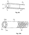
- FIG. 12A is a perspective, partially cut-away view of the inner catheter
- FIG. 13 is a plan view of the inner catheter and the delivery catheter assembled
- FIG. 14 is a side, partially cross-sectional view of the catheter assembly of FIG. 13 ;
- FIG. 15 is an enlarged view of part of the catheter assembly of FIG. 14 ;
- FIG. 16 is an enlarged view of another part of the catheter assembly of FIG. 14 ;
- FIG. 17 is a side view of the catheter assembly of FIG. 14 with the inner catheter in a distal configuration of use;
- FIG. 18 is a side, partially cross-sectional view of an embolic protection device of the embolic protection system
- FIG. 19 is a plan view of the embolic protection device of FIG. 18 ;
- FIG. 20 is a side view of a pushing device of the embolic protection system
- FIG. 21 is a side, cross-sectional view of a part of the pushing device of FIG. 8 ;
- FIG. 22 is a side, partially cross-sectional view of a loading device of the embolic protection system
- FIG. 23 is an enlarged view of the detail of the loading device of FIG. 22 ;
- FIG. 23A is a cross-sectional view of an alternative loading device
- FIGS. 24 to 27 are schematic views illustrating release and flushing of the catheter assembly of FIGS. 13 to 17 ;
- FIGS. 28 and 29 are schematic views illustrating release of the pushing device of FIGS. 20 and 21 ;
- FIG. 29A is a cross sectional view on the line AA in FIG. 29 ;
- FIGS. 30 to 32B are schematic views illustrating loading of the embolic protection device of FIGS: 18 and 19 into the catheter assembly of FIGS. 13 to 17 ;
- FIGS. 33 and 34 are schematic views illustrating disassociation of the loaded catheter assembly of FIG. 32A from the loading device of FIGS. 22 and 23 ;
- FIG. 35 is a side view of a guidewire of the embolic protection system
- FIGS. 36 to 41 are schematic views illustrating delivery and deployment of the embolic protection device of FIGS. 18 and 19 in a vasculature;
- FIGS. 42 and 43 are schematic views illustrating treatment of the vasculature
- FIGS. 44 to 47 are schematic views illustrating retrieval of the embolic protection device of FIGS. 18 and 19 from the vasculature;
- FIGS. 48 to 56 are side, partially cross-sectional views of other embolic protection devices of the embolic protection system
- FIGS. 57 and 58 are schematic views illustrating loading of embolic protection devices into the catheter assembly of FIGS. 13 to 17 ;
- FIGS. 59 to 61 are schematic views illustrating loading of the embolic protection device of FIGS. 18 and 19 into the catheter assembly of FIGS. 13 to 17 using a removable pulling device;
- FIG. 62 is a side view of the loaded catheter assembly
- FIGS. 63 and 64 are schematic views illustrating loading of embolic protection devices into the catheter assembly of FIGS. 13 to 17 using the pulling device of FIGS. 59 to 61 ;
- FIGS. 65 to 69 are schematic views illustrating retrieval of an embolic protection device from a vasculature
- FIG. 70 is a side view of another guidewire of the embolic protection system.
- FIGS. 71 to 74 are schematic views illustrating deployment of an embolic protection device in a vasculature
- FIGS. 75 and 76 are schematic views illustrating deployment of another embolic protection device in the vasculature using tethers
- FIG. 77 is a schematic view illustrating release of a tether of FIGS. 75 and 76 ;
- FIGS. 78 to 81 are schematic views illustrating delivery and deployment of an embolic protection device of a rapid exchange embolic protection system in a vasculature
- FIG. 82 is a side, partially cross-sectional view of another embolic protection system
- FIG. 83 is a side, partially cross-sectional view of a further embolic protection device.
- FIGS. 84 and 85 are cross-sectional views of a distal portion of catheters.
- transvascular embolic protection system for safely capturing and retaining embolic material released during an interventional procedure while maintaining blood flow.
- the embolic protection system comprises an embolic protection device 1 , a delivery catheter 2 for delivery of the embolic protection device 1 to a desired location in the vascular system and a proximal stop for deployment of the embolic protection device 1 .
- the device 1 is collapsible from an expanded deployed configuration to a retracted delivery configuration.
- the delivery catheter 2 has a pod 13 at the distal end to define a reception space for the embolic protection device 1 in the collapsed delivery configuration.
- the proximal stop in this case is provided by the distal end 27 of an inner catheter 25 which extends towards the pod 13 of the delivery catheter 2 for deployment of the embolic protection device 1 from the pod 13 .
- the embolic protection device 1 is loaded into the pod 13 of the delivery catheter 2 which is delivered over a pre-positioned guidewire 99 .
- the inner catheter 25 is moved relative to the delivery catheter 2 to deploy the embolic protection device 1 from the pod 13 .
- the delivery and inner catheters 2 , 25 are then withdrawn leaving a bare guidewire 99 over which various devices such as a dilation balloon and/or a stent can be advanced to the treatment site. Embolic material dislodged during the treatment procedure(s) is collected in the embolic protection device 1 .
- the device 1 may be retrieved into a retrieval catheter 3 .
- the guidewire 99 may be left in place for further catheter advancements or may be withdrawn with or subsequent to the withdrawal of the retrieval catheter 3 .
- a pack 4 is provided to safely store and prepare the embolic protection system for use.
- the pack 4 comprises a vacuum-formed tray 5 , typically of PETG.
- the tray 5 has a channel 6 extending in a looped configuration around the tray 5 for receiving the delivery catheter 2 .
- the delivery catheter 2 has a proximal end 11 and a distal end 12 .
- a handle 14 is provided at the proximal end 11
- the inner catheter 25 which extends through the delivery catheter 2 has a luer 36 at the proximal end.
- the luer 36 is located in the tray 5 adjacent to the handle 14 .
- the pod 13 is provided at the distal end 12 of the inner catheter 2 .
- a loading device 7 in the form of a funnel piece is mounted in the tray adjacent to and, in this case extending into the pod 13 .
- the embolic protection device 1 is mounted in its expanded configuration in a well 90 in the tray 5 adjacent to and extending into the loading device 7 .
- a pushing device 8 for loading the collapsible embolic protection device 1 is mounted in the tray 5 adjacent to the embolic protection device 1 .
- a syringe 91 is also mounted in a recess 92 of the tray 5 . The syringe 91 is used to flush the system and, after flushing, the pushing device 8 is used to push the embolic protection device 1 through the loading device 7 and into the pod 13 of the delivery catheter 2 in the collapsed configuration.
- the delivery catheter 2 is now ready for advancement over the guidewire 99 .
- the delivery catheter 2 comprises a tubular body 10 , typically of polyimide, or nylon extending between a proximal end 11 and a distal end 12 .
- a pod 13 is provided, the pod 13 having a smaller wall thickness and in this case a larger internal diameter, as illustrated in FIG. 4 , to define a reception space for receiving the embolic protection device in a collapsed configuration.
- the handle 14 illustrated in detail in FIGS. 5 to 7 , is attached to the proximal end 11 of the tubular body 10 , with a strain relief member 15 extending from the handle 14 partially along the tubular body 10 .
- the handle 14 defines a central lumen 16 extending between a proximal opening 17 and a distal opening 18 .
- a side port opening 19 is provided in the handle 14 , the side port 19 being in communication with the central lumen 16 ( FIG. 3 ).
- a female luer 20 as illustrated in FIG. 8 , is also provided, the luer 20 being fixedly mounted in the side port 19 .
- a double-start thread is provided at the free end of the luer 20 for threadable attachment of, for example, a flushing syringe 91 to the luer 20 .
- the proximal stop is provided by an inner catheter 25 .
- the inner catheter 25 comprises a tubular body extending between a proximal end 26 and a distal end 27 .
- the tubular body comprises an inner tubular stem 28 extending between the proximal end 26 and the distal end 27 , and an outer tubular stem 29 , typically of polyimide, extending from the proximal end 26 only partially along the inner stem 28 , as illustrated in FIG. 10 .
- the outer stem 29 terminates in a protruding O-ring shoulder 30 .
- An annular collar 31 is slidably mounted to the outer stem 29 proximally of the O-ring shoulder 30 ( FIG. 12 ).
- the female winged luer piece 36 is attached to the proximal end 26 of the stems 28 , 29 by means of a flair connector 32 .
- the winged luer 36 defines a central lumen 33 extending between a proximal opening 34 and a distal opening 35 .
- the inner catheter 25 is configured for insertion through the proximal opening 17 of the handle 14 and advancement through the handle 14 , and the tubular body 10 until the collar 31 engages the handle 14 ( FIG. 15 ) in the region of the proximal opening 17 .
- the collar 31 is fixedly attached within the proximal opening 17 of the handle 14 .
- the inner catheter 25 is slidable relative to the delivery catheter 2 between a retracted position, as illustrated in FIG. 14 , in which the distal end 27 of the inner catheter 25 is proximal of the pod 13 defining the reception space in the delivery catheter 2 ( FIG. 16 ), and an extended position, in which the distal end 27 of the inner catheter 25 extends distally of the pod 13 of the delivery catheter 2 ( FIG. 17 ). Movement of the inner catheter 25 proximally relative to the delivery catheter 2 is limited by engagement of the O-ring shoulder 30 with the collar 31 ( FIGS. 14 and 15 ).
- the pod 13 of the delivery catheter 2 and the inner stem 28 of the inner catheter 25 at least partially comprise a stiff core, for example of a metallic material, such as stainless steel, encased in a more pliable body, for example of a plastics material such as polyimide.
- the cores comprise a mesh of longitudinally oriented strips of the stiff material and circumferentially oriented strips of the stiff material.
- the outer shaft or delivery catheter 2 is subjected to high levels of tensile strain.
- the design/construction of the outer shaft 2 is such that the amount of strain energy that can be stored within the outer shaft is minimized.
- Low flexural stiffness is also desirable in catheter design to ensure good catheter flexibility, trackability and low insertion forces.
- These attributes are achieved by incorporating high tensile elements 21 within the wall construction of the outer shaft 2 .
- These high tensile elements 2 can be high tensile longitudinal steel wires as shown in the example below or they may be flexible high tensile wires or fibers, carbon fibers and or kevlar fibers. These fibers/wires are contained within the wall 22 of the catheter which may be a polymeric material (detailed in FIG.
- 4A is a polyimide wall). These wires/fibers provide the outer shaft with high tensile modulus (minimal stretch) which results in a shaft that can not store much strain energy.
- the inclusion of the above high tensile elements 21 allows for a low profile outer shaft 2 .
- This low wall thickness outer catheter shaft therefore also has low flexural stiffness, good flexibility, trackability and subsequently low insertion force.
- the inner surface 23 of the lumen of this shaft 2 is a low friction (PTFE) material to minimize the friction strain energy incurred during the deployment action.
- the inner catheter shaft 25 is subjected to high levels of compression strain.
- the design/construction of the inner shaft 25 is such that the modulus of compression is high which reduces the amount of strain energy that can be stored within the inner shaft 25 .
- the inclusion of the above high compression elements allows for a low profile outer shaft.
- the low wall thickness inner shaft will therefore also have low flexural stiffness, good flexibility and trackability.
- the example illustrated in FIG. 14A is a high compression modulus steel wire braid 24 contained within a polymeric matrix 24 A.
- the inner lumen of the shaft 25 is made of a low friction (PTFE) material layer 24 B.
- PTFE low friction
- the outer surface of the shaft 25 is also provided with a low friction (FEP) material layer 24 C.
- FEP low friction
- the layers 24 B and 24 C minimize the frictional strain energy incurred during delivery and deployment. Due to the combination of the above inner and outer shaft 2 , 25 the amount of strain energy that can be stored within the system during use is very low. Due to the low strain energy build up within the system a precise, controlled, low force deployment is achieved even in difficult vessel paths.
- the embolic protection device 1 comprises a collapsible filter element 40 for delivery through a vascular system of a patient and deployment at a desired location in the vascular system.
- FIGS. 18 and 19 illustrate the filter element 40 in detail.
- the filter element 40 comprises a collapsible filter body 41 , a collapsible filter support frame 42 contacting the filter body 41 , and an inner elongate sleeve 43 to which both the filter body 41 and the frame 42 are mounted.
- a proximal end 44 of the filter body 41 and a proximal end 45 of the frame 42 are both fixedly attached to a proximal end 46 of the sleeve 43 , in this case by means of an adhesive bond.
- a distal end 47 of the filter body 41 and a distal end 48 of the frame 42 are free to slide over a distal end 49 of the sleeve 43 .
- the filter body 41 has a proximal inlet end and a distal outlet end.
- the inlet end of the filter body 41 has one or more, in this case two, large inlet openings 50
- the outlet end has a plurality of, in this case approximately three hundred, small outlet openings 51 sized to allow through passage of blood but to retain undesired embolic material within the filter body 41 .
- the filter support frame 42 is movable between a collapsed position for movement of the filter element 40 through a vascular system and an extended outwardly projecting position to support the filter body 41 in an expanded position.
- the frame 42 has a distal section 52 , an intermediate section 53 for urging the filter body 41 in the expanded position into apposition with a vascular vessel wall, and a proximal section 54 extending proximally and radially inwardly of the intermediate section 53 ( FIGS. 18 and 19 ).
- At least part of the proximal section 54 of the frame is spaced distally of the inlet openings, 50 in the filter body 41 to accommodate inflow of embolic material through the inlets 50 and into the expanded filter body 41 .
- the filter body 41 comprises one or more, in this case two, linking webs 55 between adjacent inlets 50 , and a part of the proximal section 54 of the frame extends radially inwardly in alignment with the webs 55 , as illustrated in FIG. 19 , to avoid occluding the inlets 50 to the filter body 41 when the filter body 41 is in the expanded position. In this manner the possibility of embolic material becoming caught or hung-up on the proximal section 54 of the frame as the embolic material flows distally through the inlet openings 50 is minimized.
- the proximal section 54 of the frame comprises one or more frame elements, in this case four. At least one frame element, in this case two, provides the part of the proximal section 54 which is spaced distally of the inlets 50 , and at least one frame element, in this case two, provides the part of the proximal section 54 extending radially inwardly in alignment with the webs 55 .
- the proximal section of the frame runs generally parallel with a vessel wall and then turns radially inwards.
- the proximal arm(s) of the frame have a section that is displaced distally. The advantage of this displacement is that it creates an inlet path which is offset and therefore larger.
- the frame elements are preferably of a shape memory material, such as Nitinol, or of a superelastic material, and may have a plating of gold or other dense material around the Nitinol.
- the frame elements facilitate movement of the frame 42 between the collapsed position and the extended outwardly projecting position.
- the frame 42 is electropolished.
- the sleeve 43 defines a lumen 56 extending therethrough for exchange of the filter element 40 over the guidewire 99 .
- the distal end 49 of the sleeve 43 is engageable with a stop such as a stop on the guidewire 99 . This is particularly useful for retrieval of the filter element 40 from, a vascular system.
- the sleeve 43 is typically of polyimide.
- the sleeve 43 acts as a barrier between the lumen 56 through which a guidewire may be exchanged, and the internal annular volume of the filter body 41 within which embolic material is retained.
- the proximal end 46 of the sleeve 43 is proximal of the inlets 50
- the distal end 49 of the sleeve 43 is distal of the small outlets 51 . This ensures that all blood flows into the filter body 41 through the inlets 50 , through the filter body 41 and out of the fitter body 41 through the small outlets 51 which are sized to retain undesired embolic material within the filter body 41 .
- the sleeve 43 prevents escape of any embolic material from the filter body 41 into the lumen 56 , for example, during exchange of medical devices over a guidewire received within the lumen 56 , or during retrieval of the filter element 40 .
- a guide olive 57 is provided for atraumatic delivery of the filter element 40 through a vascular system, the guide olive 57 forms an extension of the distal end 47 of the filter body 41 and tapering distally inwardly for a smooth transition profile.
- the guide olive 57 is integral with the filter body 41 and is of the material Pellethane. As illustrated in FIGS. 18 and 19 , the guide olive 57 extends distally of the distal end 49 of the sleeve 43 .
- the region of a vasculature in which the filter element 40 is deployed is substantially straight for a length at least equal to the longitudinal length of the filter element 40 to ensure apposition of the filter body 41 with the vasculature wall.
- the overall longitudinal length of the filter element 40 is reduced to define a longitudinally compact filter element 40 .
- the user has greater freedom when choosing a site in a vasculature to deploy the filter element 40 because the length of the vasculature which is required to be straight is correspondingly reduced.
- the distal end 48 of the frame 42 acts to reinforce the proximal section of the guide olive 57 and prevents flaring of the sleeve 43 .
- the guide olive 57 has a soft distal tip 58 .
- Two gold marker bands 59 , 60 are provided mounted to the sleeve 43 .
- One marker band 59 is fixedly attached to the olive 51 and one marker band 60 is fixedly attached to the proximal end 45 of the frame 42 .
- the marker bands 59 , 60 assist in visualization of the filter element 40 during an interventional procedure.
- a transition element 61 is fixedly mounted to the proximal end 46 of the sleeve 43 , in this case by means of an adhesive bond.
- the transition element 61 is sized to fit made the lumen of the delivery catheter 2 to provide a smooth stiffness transition and prevent kinking.
- the pushing device 8 for loading the collapsible filter element 40 into the pod 13 of the delivery catheter 2 is illustrated.
- the pushing device 8 comprises a handle 70 for gripping the pushing device 8 and an elongate stem in this case provided by a wire 71 , extending from the handle 70 for threading through the lumen 56 of the filter element 40 .
- the wire 71 defines a distal stop 72 for releasably engaging with the distal end 49 of the sleeve 43 of the filter element 40 to push the filter element 40 into the pod 13 of the delivery catheter 2 .
- the distal stop 72 is provided by an end 74 of an outer hypotube 73 which extends from the handle 70 partially along the wire 71 .
- the free end 74 of the hypotube 73 forms a step from the small diameter wire 71 proximal of the step to the larger diameter hypotube 73 distal of the step.
- the small diameter is preferably approximately 0.014′′ (0.3556 mm)
- the large diameter is preferably approximately 0.018′′ (0.4572 mm).
- the hypotube 73 may be attached to the wire 71 by any suitable means, such as an adhesive means, or a mechanical keying means, or by brazing, or soldering, or welding, or by any other suitable means.
- the wire 71 may have a low friction coating, for example of polytetrafluoroethylene, for ease, of threading of the wire 71 through the filter element 40 .
- the handle 70 facilitates ease of gripping and of use of the pushing device 8 .
- distal stop 72 may be provided integral with the wire 71 , for example by machining a step in the wire 71 .
- the large diameter portion distal of the step may be only a locally defined feature on the wire 71 that does not extend distally to the handle 70 .
- the loading device 7 is illustrated in detail in FIGS. 22 and 23 .
- the loading device 7 defines a funnel having an inlet end 80 and an outlet end 81 , the inlet end 80 defining a larger cross-sectional area than the outlet end 81 , and the outlet end 81 being configured for co-operative alignment with the reception space of the delivery catheter 2 .
- the loading device 7 has means for radially compressing the filter element 40 from the extended outwardly projecting position to the collapsed position.
- the loading device 7 comprises a main support 82 having a funnel-shaped bore formed from a frusto-conical filter element receiving portion terminating in a cylindrical portion formed by a thin walled loading tube 83 projecting from the main support 82 for positioning within the reception space of the delivery catheter 2 .
- the cone angle of the bore is chosen from an angle in the range of between 15° and 65°, preferably between 35° and 45°.
- the loading tube 83 is preferably formed from polyethyleneterephthalate (PET), and is mounted on a metal spigot 84 , typically a grit blasted hypotube, by a combination of a polyolefin shrink tube bond and an adhesive bond.
- the metal spigot 84 is adhesively fixed to the main support 82 which is formed from “Perspex” or a similar material.
- the loading tube 83 may be coated with a lubricant.
- FIG. 23A there is illustrated an alternative loading device 85 in which an outer support 86 is provided around the pod 13 of the delivery catheter 2 .
- a smooth transition is provided by a funnel section 87 and the distal end of the pod 13 .
- the area between the outer support 86 and the pod 13 may be a wetted annular space for ease of mounting and demounting.
- the tray 5 includes integral projections 9 that extend into various recesses.
- the projections 9 releasably support the loading device 7 in cooperative alignment with the delivery catheter 2 before loading and during the loading procedure.
- the loading device 7 is supported with the loading tube 83 extending proximally into the reception space of the delivery catheter 2 before loading and during the loading procedure.
- the projections 9 on the channel wall are configured to releasably support the pushing device 8 in a position in which the distal stop 72 does not engage the filter element 40 before the loading procedure commences.
- the projections 9 are also configured to releasably support the luer 20 of the delivery catheter 2 in the horizontal position illustrated in FIGS. 1 and 24 . In this position it is not possible to slide the delivery catheter 2 proximally in the channel 6 , or, in the configuration illustrated, to flush the delivery catheter 2 through the luer 20 .
- a liquid retaining bath 90 is provided by recesses in the tray 5 , the bath 90 having a depth sufficient to accommodate in a totally submerged state the reception space of the delivery catheter 2 and the filter element 40 for submerged loading of the filter element 40 through the loading device 7 and into the pod 13 of the delivery catheter 2 .
- the channel 6 communicates with the bath 90
- a ramp is provided at an end of the channel 6 communicating with the bath 90 to direct the reception space downwards towards the bottom of the bath 90 but supporting the pod 13 of the delivery catheter 2 above the bottom of the bath 90 by means of a step.
- the syringe 91 is provided for flushing the delivery catheter 2 , the inner catheter 25 , the loading device 7 and the filter element 40 .
- the recess 92 is provided in the tray 5 for snap retention of the syringe 91 before use.
- the components of the embolic protection system are placed in the pack 4 in the following manner.
- the loading device 7 is snapped into place in the channel 6 , with the projections 9 releasably supporting the loading device 7 in the position illustrated in FIG. 1 .
- the inner catheter 25 is inserted through the proximal opening 17 of the handle 14 , and advanced through the handle 14 and the tubular body 10 until the collar 31 engages the proximal opening 17 of the handle 14 .
- the collar 31 is fixedly attached within the proximal opening 17 of the handle 14 by pushing the collar 31 home to create an interference fit between the collar 31 and the proximal opening walls.
- This catheter assembly is then looped through the channel 6 and held in place so that the loading tube 83 of the loading device 7 extends proximally into the pod 13 of the delivery catheter 2 .
- the wire 71 of the pushing device 8 is then threaded through the filter element 40 , a proximal end of the wire 71 is inserted through the loading device 7 and extended partially through the inner catheter 25 .
- the handle 70 is snapped into place in the channel 6 by the projections 9 .
- the filter element 40 is slidable over the wire 71 but is normally positioned within the bath 90 , as illustrated in FIG. 1 .
- the projections 9 retain the pushing device 8 in a position in which the distal stop 72 is spaced distally of the bath 90 , and so the distal stop 72 does not engage the filter element 40 in this storage configuration, as illustrated in FIG. 1 .
- the syringe 91 is snapped into place in the recess 92 , and the assembled pack 4 is now ready to be sealed and stored until required for use.
- the filter element 40 is in the expanded configuration. This is an advantageous arrangement. If the filter element 40 was loaded into the delivery catheter 2 and stored in the collapsed position for a long period of time, the filter element 40 would be subject to material deformation, in particular to material creep.
- the assembled pack 4 of the invention may be safely stored for long periods in a packaged configuration without risk of filter element material deformation.
- the pack 4 is placed in a porch and sealed.
- the seal is broken, the pack 4 is removed and the syringe 91 is removed from the recess 92 .
- the luer 20 of the delivery catheter 2 is rotated through 90° in a “bolt-action” to release the luer 20 from the snap-fit retaining projections 9 in the tray 5 , as illustrated in FIGS. 24 and 25 .
- the delivery catheter 2 is now slidable proximally in the channel 6 , and the luer 20 is now accessible for flushing ( FIG. 25 ).
- the syringe 91 is used to flush the delivery catheter 2 through the luer 20 ( FIG.
- a saline solution is generally used for flushing the catheters 2 , 25 .
- the syringe 91 is also used to fill the bath 90 with saline solution, thereby immersing the filter element 40 , the reception space of the delivery catheter 2 and the loading device 7 in the saline solution. This ensures all removed from the system.
- This flushing step is performed shortly before intended use.
- the filter element 40 is completely visible and accessible to the user during prepping in this way, the user can squeeze or pinch parts of the filter element 40 to ensure the filter element 40 is completely flushed of air. This is difficult if the filter element 40 was loaded into the delivery catheter 2 upon assembly and stored for a potentially long period in the collapsed position.
- the flushed filter element 40 is now ready for loading into the pod 13 of the delivery catheter 2 .
- the pushing device 8 is rotated through 90° in a “bolt action” to release the handle 70 from the snap-fit retaining projections 9 in the tray 5 , as illustrated in FIGS. 28 and 29 . In this configuration the pushing device is still retained to the tray ( FIG. 29A ).
- the pushing device 8 is now free to slide proximally in the channel 6 ( FIG. 30 ), until the distal stop 72 engages with the distal end 49 of the sleeve 43 of the filter element 40 ( FIGS. 31A and 31B ). Continued pushing of the pushing device 8 will push the filter element 40 proximally towards the loading device 7 ( FIG.
- the loading device 7 has thus far remained in co-operative alignment with the delivery catheter 2 . Because the luer 20 of the delivery catheter 2 has been released from the snap-fit retaining projections 9 in the tray 5 , as illustrated in FIG. 32B , the catheter assembly is free to slide proximally in the channel 6 away from the loading device 7 . When the pushing device 8 is further pushed proximally, this causes the inner catheter 25 to move proximally and with it the delivery catheter 2 due to the engagement of the O-ring shoulder 30 with the handle 14 . In this manner, the delivery catheter 2 , the inner catheter 25 and the collapsed filter element 40 are all moved together proximally away from the loading device 7 , and thereby the loaded catheter assembly is disassociated from the loading device 7 ( FIG. 33 ).
- the loaded catheter assembly is then removed from the channel 6 leaving the loading device 7 and the pushing device 8 behind in the channel 6 .
- the assembly of the loaded delivery catheter 2 and the inner catheter 25 as illustrated in FIG. 34 , is now ready for insertion into a vascular system of a patient.
- the filter element 40 is loaded into the pod 13 of the delivery catheter 2 by a simple, single-direction pushing action. This minimizes potential loading difficulties.
- the components of the pack 4 are retained in the correct loading alignments by the tray 5 .
- the pushing device 8 is completely separated from the loaded catheter assembly after completion of the loading procedure.
- the loaded filter element 40 is not attached or associated in any way with the pushing device 8 .
- the user is free to choose any suitable guidewire, as desired, for subsequent delivery of the filter element 40 through a vascular system of a patient.
- the guidewire 99 is suitable for the exchange of the filter element 40 through a vascular system of a patient over the guidewire 99 .
- the guidewire 99 defines a distal end 100 and comprises a distal stop 101 to prevent relative movement of the filter element 40 distally of the distal end 100 of the guidewire 99 .
- the portion of the guidewire 99 proximally of the distal stop 101 is bare for exchange of the filter element 40 and/or other medical devices over the guidewire 99 .
- the distal stop 101 is provided by a wire coil 102 fixedly attached around the distal end 100 of the guidewire 99 ( FIG. 35 ).
- the coil 102 has a larger outer diameter than the bare portion of the guidewire 99 to define a step from the small diameter bare portion of the guidewire 99 to the large diameter coil portion of the guidewire 99 .
- the small diameter is preferably approximately 0.014′′ (03556 mm), and the large diameter is preferably 0.018′′ (0.4572 mm).
- a curve is typically formed towards the distal end 100 of the guidewire 99 to facilitate navigating and/or positioning the guidewire 99 in a vasculature.
- the coil 102 may be attached to the small diameter portion of the guidewire 99 by an adhesive means, or by a mechanical keying means, or by brazing, or soldering, or welding, or by any other suitable means of attachment.
- the guidewire 99 is partially of stainless steel, and partially of a radiopoque material to aid the user in positioning the guidewire 99 accurately in a vasculature.
- the guidewire 99 has a coating of a low friction material, for example of a fluoropolymer such as polytetrafluoroethylene, or of a silicone material, or of a hydrophilic material, for ease of advancement of the guidewire 99 through a vasculature and ease of exchange of the filter element 40 and/or other medical devices over the guidewire 99 .
- the large diameter coil 102 extends distally of the step to the distal end 100 of the guidewire 99 .
- the large diameter portion of the guidewire 99 may extend distally of the step only a part of the distance to the distal end 101 of the guidewire 99 .
- the large diameter portion may taper distally inwardly back to the small diameter in an arrow-head type shape or by gradually tapering.
- the guidewire 99 will be selected to suit the geometry of the vasculature 110 to be negotiated, and/or the disease site, and/or the preference of the user.
- the guidewire 99 is firstly inserted on its own into the vasculature system of a patient and advanced through the vasculature 110 until the distal stop 101 of the guidewire 99 is distal of a treatment site such as a region of stenosis 111 in the vasculature 110 ( FIG. 36 ).
- the curved distal end 100 of the guidewire 99 is often anchored in a bend in the vasculature 110 distally of the stenosed region 111 ( FIG. 41 ) to facilitate some straightening of the anatomy by the user prior to delivery of the filter element 40 .
- the loaded delivery catheter assembly of FIG. 34 is then inserted into the vasculature system and advanced over the guidewire 99 through the vasculature 110 , until the pod 13 of the delivery catheter 2 with the collapsed filter element 40 therein is positioned at a desired location of the vasculature 110 distally of the stenosed region 111 ( FIG. 37 ).
- At least part of the filter element 40 in this case part of the distal end 58 of the guide olive 57 , protrudes distally out of the pod 13 of the delivery catheter 2 during advancement of the delivery catheter 2 through the vascular system to minimize trauma to the vessel walls.
- the olive also provides a stiffness transition.
- the delivery catheter 2 is refracted while maintaining the position of the inner catheter 25 ( FIG. 38 ).
- the distal end 27 of the inner stem 28 of the inner catheter 25 acts as a proximal stop against which the transition element 61 of the filter element 40 abuts, thus the distal end 27 of the inner stem 28 of the inner catheter 25 prevents retraction of the collapsed filter element 40 with the delivery catheter 2 .
- the filter element 40 is freed to expand from the collapsed, delivery configuration to the extended, outwardly projecting position of FIG. 39 .
- the filter element 40 may alternatively be deployed by advancing the inner catheter 25 while maintaining the position of the delivery catheter 2 .
- the distal end 27 of the inner stem 28 of the inner catheter 25 effectively acts as a pusher to eject the collapsed filter element 40 from the pod 13 of the delivery catheter 2 , and thereby facilitate expansion of the filter element 40 to the deployed configuration of FIG. 39 .
- the filter element 40 may be deployed by any sufficient movement of the delivery catheter 2 proximally relative to the inner catheter 25 , thereby engaging the distal end 27 of the inner stem 28 of the inner catheter 25 with the filter element 40 to facilitate deployment of the filter element 40 .
- the construction of the pod 13 of the delivery catheter 2 and the inner stem 28 of the inner catheter 25 prevent deformation of the pod 13 and the inner stem 28 during deployment of the filter element 40 .
- elongation of the pod 13 and compression of the inner stem 28 are avoided. This ensures that the filter element 40 is accurately and smoothly deployed in the desired location in the vasculature 110 .
- the filter body 41 In the extended outwardly projecting position the filter body 41 is in complete circumferential apposition with the wall of the vasculature 110 over a length substantially equal to the intermediate section 53 of the filter support frame 42 .
- both the delivery catheter 2 and the inner catheter 25 are retracted and withdrawn from the vasculature 110 , leaving the guidewire 1 in place in the vasculature 110 , and the deployed filter element 40 in place in the vasculature 110 distally of the stenosed region 111 ( FIGS. 40 and 41 ).
- the guidewire 99 is not attached to the filter element 40 , and thus the guidewire 99 is free to rotate and/or to move longitudinally relative to the deployed filter element 40 .
- This is highly advantageous as it prevents any accidental movement of the guidewire 99 causing twisting and/or dislodging of the deployed filter element 40 .
- the user has more freedom to carry out a treatment procedure on the stenosed region 111 without the risk of intimal abrasion, or of the deployed filter element 40 becoming dislodged or in some other way creating a potential flow path for embolic material around the filter element 40 .
- the portion of the guidewire 99 in place in the vasculature 110 proximal of the deployed filter element 40 is bare.
- This bare portion of the guidewire 99 facilitates the, exchange of a wide variety of different medical devices, for example a treatment means, over the bare guidewire 99 while the deployed filter element 40 remains in place in the vasculature 110 .
- medical devices are atherectomy devices to carry out an atherectomy procedure on the stenosed region 111 , or an angioplasty balloon 112 to carry out an angioplasty procedure on the stenosed region 111 , as illustrated in FIG. 42 , or a stent 113 to carry out a stenting procedure on the stenosed region 111 , as illustrated in FIG. 43 , or any possible combination of these procedures, or any other therapeutic or diagnostic procedure. Any embolic material released during such an interventional procedure will be collected and safely retained in the filter element 40 .
- the retrieval catheter 3 After completion of an interventional procedure, for example a treatment of the stenosed region 111 , the retrieval catheter 3 is flushed, for example with a saline solution, using the syringe 91 .
- the retrieval catheter 3 comprises an elongate tubular centering catheter 121 .
- the centering catheter 121 has a tapered distal tip 122 which protrudes distally of a distal end 120 of the retrieval catheter 3 during advancement through the vasculature 110 , as illustrated in FIG. 44 , to prevent snagging of the retrieval catheter 3 on the stent 113 , and to minimize vessel trauma.
- the retrieval catheter 3 is inserted into the vascular system and advanced over the bare guidewire 99 until the distal end 120 of the retrieval catheter 3 is distal of the stent 113 ( FIG. 44 ). The retrieval catheter 3 is then further advanced distally over the guidewire 99 while maintaining the position of the centering catheter 121 until the distal end 120 of the retrieval catheter 3 is immediately proximal of the deployed filter element 40 . The guidewire 99 is retracted to engage the distal stop 101 with the distal end 49 of the sleeve 43 of the filter element 40 .
- the distal stop 101 of the guidewire 99 may alternatively be engaged with the distal end 49 of the sleeve 43 of the filter element 40 by advancing the retrieval catheter 3 further distally to engage the deployed filter element 40 and push the deployed filter element 40 distally until the distal end 49 of the sleeve 43 of the filter element, 40 engages the distal stop 101 of the guidewire 99 . In this case no retraction of the guidewire 99 is necessary to engage the distal stop 101 with the distal end 49 of the sleeve 43 of the filter element 40 .
- any suitable combination of advancement of the retrieval catheter 3 and retraction of the guidewire 99 may be employed to effect engagement of the distal stop 101 of the guidewire 99 with the distal end 49 of the sleeve 43 of the filter element 40 .
- the retrieval catheter 3 With the distal stop 101 of the guidewire 99 engaging the distal end 49 of the sleeve 43 of the filter element 40 , the retrieval catheter 3 is advanced while maintaining the position of the guidewire 99 ( FIG. 45 ). This causes the filter element 40 to collapse into the retrieval catheter 3 until the filter element 40 is retrieved into the retrieval catheter 3 ( FIG. 46 ).
- the filter element 40 may alternatively be retrieved into the retrieval catheter 3 by retracting the guidewire 99 while maintaining the position of the retrieval catheter 3 to collapse and retrieve the filter element 40 into the retrieval catheter 3 .
- the guidewire 99 acts to pull the filter element 40 proximally into the retrieval catheter 3 .
- the filter element 40 may be retrieved by any suitable movement of the retrieval catheter 3 distally relative to the guidewire 99 .
- the distal stop 101 facilitates retrieval of the filter element 40 by preventing the filter element 40 moving distally of the distal end 100 of the guidewire 99 .
- the guide olive 57 of the filter element 40 may or may not protrude distally out of the distal end 120 of the retrieval catheter 3 after collapse of the filter element 40 .
- the retrieval filter element 40 is then withdrawn from the vasculature 110 by withdrawing the retrieval catheter 3 and the centering catheter 121 together from the vasculature 110 .
- the guidewire 99 may be left in place in the vasculature 110 after the retrieval catheter 3 , the centering catheter 121 , and the retrieval filter element 40 have been withdrawn from the vasculature 110 , as illustrated in FIG. 47 .
- the guidewire 1 may be withdrawn from the vasculature 110 upon withdrawal of the retrieval catheter 3 , the centering catheter 121 , and the retrieval filter element 40 .
- a further treatment or diagnostic means may be advanced over the bare guidewire 99 to access any desired location in the vasculature 110 .
- the position of the bare guidewire 99 may be adjusted, proximally or distally, as desired, to suit a further treatment or diagnostic procedure. Otherwise a fluoroscopic assessment of the treated vessel may be made through the guiding catheter or sheath prior to withdrawal of the guidewire. This is desirable.
- the embolic protection system of the invention offers considerable clinical advantages.
- the arrangement allows a clinician to select a suitable guidewire from a range of such guidewires. This provides enhanced flexibility by ensuring that filter performance can be optimized.
- the embolic protection device is not dedicated to a particular guidewire.
- the guidewire which is first advanced through a vasculature can have a low profile and be tailored to the proposed procedure or vasculature. Consequently, the guidewire can easily navigate narrow and tortuous regions of the vasculature.
- a clinician may readily select a particular type of guidewire which provides the appropriate flexibility and performance required for a particular vascular procedure being performed.
- the system also facilitates the safe crossing of a lesion not only in a first lesion.
- embolic protection device is not attached to the guidewire, if the embolic protection device is undersized with respect to the region of the treatment site it is free to be carried by blood flow to a distal narrowed section of the vasculature at which the embolic protection device effectively achieves apposition with the vessel wall. This ensures that all blood flow with entrained embolic material passes through the embolic protection device.
- the guidewire distal stop prevents movement of the embolic protection device distally off the guidewire.
- the possibility of successfully delivering other catheters and interventional devices to the lesion area is enhanced because of the independent movement compatibility of the deployed filter, and guidewire.
- the guidewire tip can be advanced into the distal vasculature to provide anchorage during the advancement of additional catheters and devices.
- the filter position is maintained by visual apposition and blood flow forces.
- the wire provides extra support to the catheter or interventional device being advanced. This increases the possibility of delivering the catheter to the intended location and minimizes the possibility of an uncontrolled proximal movement of the guidewire/filter. This uncontrolled proximal movement occurs when the guidewire has insufficient support to guide an advancing catheter, through a tortuous path.
- With fixed wire systems the filter may be quickly withdrawn back into the lesion area with increased, risk of an embolic event or stent dislodgement.
- the design of this invention substantially eliminates some of these serious clinical risks.
- FIGS. 48 to 56 there is illustrated other embolic protection devices which are similar to the embolic protection device of FIGS. 1 to 47 , and similar elements are assigned the same reference numerals in FIGS. 48 to 56 .
- the lumen 56 of the sleeve 43 is of a diameter greater than the outer diameter of the pushing device distal stop 72 , and greater than the diameter of the guidewire distal stop 101 .
- the distal end 49 of the sleeve 43 is not engageable with either the distal stop 72 of the pushing device 8 or the distal stop 101 of the guidewire 99 .
- an engagement grip 130 is provided on an inner wall of the sleeve 43 , the engagement grip 130 providing an abutment for engagement with the distal stop 72 of the pushing device 8 , and for engagement with the distal stop 101 of the guidewire 99 .
- the engagement grip 130 may be provided at the proximal end 46 of the sleeve 43 ( FIGS. 48 and 50 ) or at the distal end 49 of the sleeve 43 , or at any suitable point along the length of the sleeve 43 as desired ( FIGS. 49 and 51 ).
- the engagement grip 130 may be provided by a relatively short stop rigidly attached to the inner wall of the sleeve 43 , as illustrated in FIGS. 48 and 49 , for example by chemical means, such as an adhesive, or by mechanical means, such as welding, or brazing, or soldering, or keying means.
- the engagement grip 130 may be provided by crimping a portion of the sleeve 43 , as illustrated in FIGS. 50 and 51 .
- the distal end 49 of the sleeve 43 is engageable with the distal stop 72 of the pushing device 8 , and the distal stop 101 of the guidewire 99 .
- the sleeve 43 does not extend along the length of the filter body 41 as far distally as in the embolic protection device of FIGS. 1 to 51 .
- the sleeve 43 may terminate close to the distal end 47 of the filter body 41 ( FIG. 52 ), or close to the proximal end 44 of the filter body 41 ( FIG. 54 ), or at any suitable point along the filter body 41 ( FIG. 53 ).
- a distal portion of the lumen 56 of the sleeve 43 is of a diameter greater than the outer diameter of the pushing device distal stop 72 , and greater than the diameter of the guidewire distal stop 101 , and a proximal portion of the lumen 56 of the sleeve 43 is of a smaller diameter to facilitate engagement of the distal stop 72 of the pushing device 8 and engagement of the distal stop 101 of the guidewire 99 with a step 140 in the sleeve 43 .
- the step 140 may be provided by overlapping a small diameter sleeve with a large diameter sleeve ( FIG. 55 ), or alternatively the step 140 may be provided integral with the sleeve 43 for example by machining the step 140 into the sleeve 43 .
- FIG. 57 there is illustrated the loading of an embolic protection device, which is similar to that illustrated above in FIG. 49 , into the pod 13 at the distal end 12 of the delivery catheter 2 .
- the loading procedure is similar to that described above with reference, in particular, to FIGS. 28 to 34 .
- the distal stop 72 on the pushing device 8 engages the engagement grip 130 on the inner wall of the sleeve 43 to push the embolic protection device through the loading device 7 and into the delivery catheter reception space, thereby collapsing the embolic protection device, as described previously.
- FIG. 58 illustrates the loading of an embolic protection device, which is similar to that illustrated above in FIG. 48 , into the pod 13 of the delivery catheter 2 .
- engagement grip 130 may be of any suitable configuration that facilitates engagement with the distal stop 72 of the pushing device 8 for loading the embolic protection device into the pod 13 of the delivery catheter 2 .
- FIGS. 59 to 62 there is illustrated an alternative loading of the filter element 40 into the pod 13 at the distal end 12 of the delivery catheter 2 , which is similar to the loading procedure described above with reference, in particular, to FIGS. 28 to 36 .
- a pulling device 150 is provided in place of the pushing device 8 .
- the pulling device 150 is similar to the pushing device 8 described above, in particular with reference to FIGS. 20 and 21 .
- the wire 71 of the pulling device 150 extends proximally through the inner catheter 25 , and out of the proximal opening 34 of the catheter for manipulation by a user.
- the filter element 40 is loaded by pulling the pulling device 150 proximally to engage the distal stop 72 of the pulling device 150 with the distal end 49 of the sleeve 43 . Further pulling of the pulling device 150 draws the filter element 40 through the loading device 7 and into the pod 13 at the distal end 12 of the delivery catheter 2 , thereby collapsing the filter element 40 , in a manner similar to that described previously. Further pulling of the pulling device 150 proximally disassociates the loaded catheter assembly from the loading device 7 ( FIG. 62 ), as described previously.
- FIG. 63 there is illustrated the loading of an embolic protection device, which is similar to that illustrated above in FIG. 49 , into the pod 13 at the distal end 12 of the delivery catheter 2 .
- the loading procedure is similar to that described above in FIGS. 59 to 62 .
- the distal stop 72 of the pulling device 150 engages the engagement grip 130 on the inner wall of the sleeve 43 to pull the embolic protection device through the loading device 7 and into the delivery catheter reception space, thereby collapsing the embolic protection device.
- FIG. 64 illustrates the loading of an embolic protection device, which is similar to that illustrated above in FIG. 48 , into the pod 13 of the delivery catheter 2 using the pulling device 150 .
- FIGS. 65 to 69 there is illustrated the retrieval of an embolic protection device, which is similar to that described above in FIG. 48 , into the retrieval catheter 3 .
- the retrieval procedure is similar to that described above with reference, in particular, to FIGS. 44 to 47 .
- the distal stop 101 on the guidewire 99 engages the engagement grip 130 on the inner wall of the sleeve 43 to prevent the embolic protection device moving distally relative to the distal stop 101 on the guidewire 1 during retrieval.
- engagement grip 130 may be of any suitable configuration that facilitates engagement with the distal stop 101 of the guidewire 99 for retrieving the deployed embolic protection device into the retrieval catheter 3 .
- FIG. 70 illustrates another guidewire 160 of the embolic protection system, which is similar to the guidewire 99 of FIGS. 1 to 69 , and similar elements are assigned the same reference numerals in FIG. 70 .
- the guidewire 160 does not comprise a step from a small diameter portion to a large diameter portion.
- FIGS. 71 to 74 illustrate the deployment of an embolic protection device of the embolic protection system which has been delivered over the guidewire 160 of FIG. 70 .
- the delivery and deployment procedure is similar to that described above with reference, in particular to FIGS. 36 to 41 .
- a tapered ring 161 is provided slidably mounted on the guidewire 160 between the distal end 27 of the inner stem 28 of the inner catheter 25 and a proximal end 163 of the embolic protection device.
- the delivery catheter 2 is retracted while maintaining the position of the inner catheter 25 .
- the retraction of the delivery catheter 2 initially draws the embolic protection device proximally due to the frictional force acting between the pod 13 of the delivery catheter 2 and the embolic protection device ( FIG. 71 ).
- the embolic protection device is initially drawn proximally it abuts the tapered ring and pushes the tapered ring 161 proximally until the tapered ring 161 abuts the distal end 27 of the inner stem 28 of the inner catheter 25 ( FIG. 72 ).
- the embolic protection device is retrieved in a manner similar to that described previously with reference to FIGS. 44 to 47 .
- the retrieval catheter 3 is advanced over the guidewire 160 until the retrieval catheter 3 is proximally adjacent the deployed embolic protection device.
- the retrieval catheter 3 is then further advanced while maintaining the position of the guidewire 160 to collapse and retrieve the embolic protection device into the retrieval catheter 3 . Because the embolic protection device is taper-locked to the guidewire 160 it is not necessary to provide a distal stop on the guidewire 160 for abutment with the embolic protection device.
- the taper-lock ensures no movement of the deployed embolic protection device distally relative to the guidewire 160 is possible, and thus facilitates retrieval of the embolic protection device into the retrieval catheter 3 .
- the retrieved embolic protection device is then withdrawn from the vasculature 110 by withdrawing the retrieval catheter 3 and the guidewire 160 together.
- FIGS. 75 to 77 there is illustrated an embolic protection system which is similar to the embolic protection system described above with reference to FIGS. 71 to 74 , and similar elements are assigned the same reference numerals in FIGS. 75 to 77 .
- the embolic protection system comprises two tethers 170 with inwardly arcing hooks 172 at distal ends of the tethers 170 , the tethers 170 extending between the inner catheter 25 and the delivery catheter 2 .
- the embolic protection device comprises co-operating recesses 171 in the proximal end 163 of the embolic protection device for receiving the tether hooks 172 , as illustrated in FIG. 76 .
- Deployment of the embolic protection device proceeds in a manner similar to that described above with reference to FIGS. 71 to 74 .
- the tethers 170 are also retracted to ensure that the embolic protection device is drawn proximally to effect a secure taper-lock of the embolic protection device to the guidewire 160 ( FIG. 76 ).
- the tethers 170 act in addition to the frictional force between the pod 13 of the delivery catheter 2 and the embolic protection device to draw the embolic protection device proximally.
- the hooks 172 of the tethers 170 are unclipped by advancing the inner catheter 25 ( FIGS. 76 and 77 ).
- the distal end 27 of the inner stem 28 of the inner catheter 25 engages the hooks 172 and levers the hooks 172 outwardly disengaging the hooks 172 from the co-operating recesses 171 ( FIG. 77 ).
- the tethers 170 and the inner catheter 25 are then withdrawn from the vasculature 110 to leave the deployed embolic protection device in place in the vasculature 110 taper-locked to the bare guidewire 160 .
- FIGS. 78 to 81 there is illustrated a rapid exchange embolic protection system which is similar to the embolic protection systems of FIGS. 1 to 77 , and similar elements are assigned the same reference numerals in FIGS. 78 to 81 .
- the pod 13 of the delivery catheter 2 comprises an elongate slit 180 and the inner stem 28 of the inner catheter 25 comprises a rapid exchange aperture 181 for passage of a guidewire 182 through the aperture 181 and the slit 180 ( FIG. 78 ).
- the embolic protection device is delivered to a desired location in the vasculature 110 distally of the stenosed region 111 ( FIG. 78 ) in a manner similar to that described previously with reference to FIGS. 36 and 37 .
- the embolic protection device is deployed by retracting the delivery catheter 2 while maintaining the position of the inner catheter 25 ( FIGS. 79 to 81 ), which facilitates deployment of the embolic protection device in a manner similar to that described previously with reference to FIGS. 38 and 39 .
- the slit 180 in the pod 13 of the delivery catheter 2 is aligned with the rapid exchange aperture 181 in the stern 28 of the inner catheter 25 to prevent occlusion of the rapid exchange aperture 181 during the relative movement of the delivery catheter 2 and the inner catheter 25 .
- the aperture 181 provided in a sidewall of inner stem 28 of inner catheter is preferably located at a position along the length of the inner catheter which is spaced a relatively longer distance from the proximal end of the catheter than from the distal end of the catheter.
- delivery catheter 2 desirably incorporates an elongate slit 180 which is located adjacent the distal end the catheter and co-operates with aperture 181 and the guide wire 182 which exits therethrough to facilitate a rapid exchange of the catheter and filter assembly over the guide wire, thereby promoting ease of exchange without the necessity of utilizing exchange wires or extension wires. As illustrated in FIGS. 78-81 , this arrangement permits use of rapid exchange wire techniques as well as controlled deployment and retrieval of the filter at the delivery pod portion 13 located at the distal end of delivery catheter 2 .
- a shorter guidewire may be used than for conventional systems making the device less cumbersome.
- the guidewire 99 includes a proximal stop provided by a step 201 and the filter has a proximal engagement element provided by integral projections 202 which extend radially inwardly.
- the projections 202 are configured to pass over the proximal step 201 when the filter element is being moved distally over the guidewire 99 for deployment but are prevented from moving proximally over the proximal step 201 .
- the filter element, on deployment can move between the proximal and distal stops on the guidewire.
- the arrangement may allow the filter to be retrieved over the proximal step 202 .
- FIG. 83 there is illustrated a system 205 similar to that of FIG. 82 and like parts are assigned the same reference numerals.
- the proximal step on the guidewire is provided by a proximally tapering element 206 .
- the embolic protection device is not restricted to use with a particular guidewire because it is not attached or engaged with the guidewire in any way as it is advanced over the guidewire. This is a highly advantageous arrangement. If the guidewire proves unsuitable for some reason, for example because it is too large or not trackable enough to access a desired site in a vascular system, the guidewire may be replaced with a more suitable guidewire, for example a guidewire with greater flexibility. However, because the embolic protection device is independent of the guidewire it may be used with any suitable guidewire.
- the invention gives greater freedom to a user by providing a choice of guidewires to suit a patient anatomy without requiring the user to select the embolic protection device to be used with the guidewire until after successful crossing of a lesion with the guidewire.
- vascular catheter functions are facilitated by the invention, such as:
- the embolic protection device can be retrieved if desired, in order to inject dye (over the remaining guidewire), such that minimal obstruction or interference occurs with the subsequent dye flow measurements.
- the wire can also be safely partially-retracted “behind” or “upstream” of the treated area, prior to performing the dye injection.
- lytic agents can be site-specifically delivered to a region of interest, either with the embolic protection device deployed, or with the embolic protection device retrieved, if desired.
- the retrieval sheath can also facilitate safe removal of the embolic protection device following a stenting procedure.
- the process of removing the embolic protection device favors certain sheath designs, such as a tapered distal tip.
- the distal tip of the sheath needs to permit easy crossing of the stent in a manner which will not catch up or “snag” at the proximal edge of the implanted stem, nor along any inwardly-projecting surface of the interior of the implanted stent, as the sheath is being introduced.
- the distal region of the retrieval sheath is also preferably formed of a material which permits radial expansion at the distal tip in order to accommodate retrieval of the embolic protection device.
- this embolic protection system accommodates barewire introduction, it is possible to replace a guidewire during a procedure, if desired. For example, during treatment of two or more, distally spaced-apart lesions, it may become necessary to replace the initial guidewire during the procedure with another guidewire offering improved steering or distal flexibility.
- the present invention might support such guidewire replacements as follows. First, the embolic protection device is retrieved into the retrieval sheath (which has already crossed the first lesion area). Then the wire can be withdrawn (or alternatively, the wire and embolic protection device together can be withdrawn), while the sheath remains across the lesion. Subsequently, a replacement guidewire can be introduced through the sheath lumen to the area of interest.
- a number of engagement means between the embolic protection device and the guidewire are described above which ensure that the embolic protection device is anchored or tethered while the retrieval sheath is advanced over the embolic protection device. It is also envisaged that an engagement means may be provided between the embolic protection device and the retrieval sheath after the filter is retrieved, to ensure that there is a positive engagement between the embolic protection device and the sheath.
- frictional engagement means may be provided on one or both of the embolic protection device and sheath.
- projections, rings, or the like may be provided on the inner surface of the retrieval sheath adjacent the distal end thereof to provide a frictional fit with the retrieved embolic protection device. Typical arrangements 210 ; 220 of this type are illustrated in FIGS. 84 and 85 .
- the frictional engagement may be provided by projections 225 which may be of any type including continuous, discontinuous, radially and/or longitudinally extending.
Abstract
Description
-
- a guidewire for advancing through a vasculature, the guidewire having a distal end and a proximal end;
- an embolic protection filter having a filter body with a distal end and a proximal end, the filter body providing for a collapsed configuration and an expanded deployed configuration;
- the embolic protection filter body having a guidewire path for slidably receiving the guidewire to permit movement of the filter relative to the guidewire when the filter is in the collapsed configuration and the expanded deployed configuration;
- a delivery catheter advanceable over the guidewire for delivery of the embolic protection filter; the delivery catheter having a proximal end and a distal end, the filter being deployed from the distal end of the delivery catheter into the expanded deployed configuration;
- a retrieval catheter advanceable over the guidewire for retrieval of the filter, the retrieval catheter having a distal end and a proximal end; and
- engagement elements for engaging the embolic protection filter with the guidewire for retrieval of the filter into the retrieval catheter in the collapsed configuration.
-
- advancing a guidewire through a vasculature;
- crossing a desired treatment location with the guidewire;
- introducing over the guidewire a collapsible embolic protection filter having a collapsed configuration, the collapsed configuration permitting delivery and withdrawal of the filter;
- deploying the filter distal to the treatment location;
- carrying out the interventional procedure, embolic material generated during the treatment procedure being captured by the deployed filter;
- advancing a retrieval catheter over the guidewire;
- collapsing the filter into the retrieval catheter and with it the captured embolic material;
- withdrawing the retrieval catheter and the collapsed filter from the vasculature leaving the guidewire in the vasculature.
-
- loading the filter in a collapsed configuration within a delivery catheter;
- advancing the delivery catheter and filter over the guidewire to deliver the filter to a desired location; and
- deploying the filter from the delivery catheter at the desired location.
-
- collapsing the filter from an expanded configuration for loading the filter into the delivery catheter;
- the filter being expanded to a deployment configuration on release from the delivery catheter.
-
- an outer catheter tube defining a distal end; and
- an inner catheter tube defining a distal end;
- the outer tube being at least partially movable relative to the inner tube between a delivery configuration in which the distal end of the outer tube extends distally of the distal end of the inner tube to define a reception space for an embolic protection filter within the outer tube, and a deployment configuration in which the distal end of the inner tube extends distally of the distal end of the outer tube for deployment of the embolic protection filter;
- the inner catheter tube providing compressive resistance and the outer catheter tube providing stretch resistance.
-
- a collapsible filter element for delivery through a vascular system of a patient;
- the filter element comprising a collapsible filter body and a collapsible filter support frame contacting the filter body;
- the filter body having an inlet end and an outlet end, the inlet end of the filter body having one or more inlet openings sized to allow blood and embolic material enter the filter body, the outlet end of the filter body having a plurality of outlet openings sized to allow through passage of blood but to retain undesired embolic material within the filter body;
- the filter support frame being movable between a collapsed position for movement through the vascular system and an extended outwardly projecting position to support the filter body in an expanded position;
- the frame having an intermediate section to urge the filter body in the expanded position into apposition with a vessel wall, and a proximal section extending radially inwardly of the intermediate section;
- at least part of the proximal section of the frame being spaced distally to accommodate inflow of embolic material through the inlet openings in the expanded position.
-
- a catheter defining a reception space at a distal end of the catheter for receiving a collapsed embolic protection filter;
- a separate removable pushing device for delivering the medical device into the reception space.
-
- providing an embolic protection filter, the embolic protection device being collapsible;
- providing a embolic protection catheter defining a reception space at a distal end of the catheter for receiving the collapsed embolic protection filter;
- providing a pushing device for delivering the embolic protection filter into the reception space;
- delivering the embolic protection filter into the reception space using the pushing device; and
- removing the pushing device from the reception space.
-
- providing a loading device to collapse the embolic protection filter, the loading device defining an inlet end and an outlet end;
- aligning the outlet end of the loading device in co-operation with the reception space; and
- delivering the embolic protection filter through the inlet end of the loading device and into the reception space.
-
- providing a embolic protection filter, the embolic protection filter being collapsible;
- providing a catheter defining a reception space at a distal end of the catheter for receiving the collapsed embolic protection filter, the catheter comprising at least one internal proximal stop;
- providing a loading device to collapse the embolic protection filter, the loading device defining an inlet end and an outlet end;
- aligning the outlet end of the loading device with the reception space;
- delivering the embolic protection filter through the loading device and into the reception space; and
- moving the collapsed embolic protection filter towards its proximal end in the reception space to engage said at least one the internal proximal stop and disassociate the loaded catheter from the loading device.
-
- providing a pushing device for delivering the embolic protection filter through the loading device and into the reception space, and for engaging the collapsed embolic protection filter with the internal proximal stop; and
- removing the pushing device after disassociating the loaded catheter from the loading device.
-
- Initial crossing with a bare guidewire is easier as a bare guidewire has an extremely low profile, is highly trackable and highly pushable.
- Attempted crossing with a bare guidewire presents a very low risk of an embolic event due to its low profile, and atraumatic tip.
- Once the bare wire is across the lesion, crossing with the filter delivery system is simplified. Advancing the tip of the guidewire and positioning it in the distal vasculature provides additional support to the filter delivery catheter.
Claims (10)
Priority Applications (1)
| Application Number | Priority Date | Filing Date | Title |
|---|---|---|---|
| US11/669,460 US7846176B2 (en) | 1997-11-07 | 2007-01-31 | Embolic protection system |
Applications Claiming Priority (20)
| Application Number | Priority Date | Filing Date | Title |
|---|---|---|---|
| IE970789 | 1997-11-07 | ||
| IE970789 | 1997-11-07 | ||
| IE980267 | 1998-04-08 | ||
| IE980267 | 1998-04-08 | ||
| US09/188,472 US6336934B1 (en) | 1997-11-07 | 1998-11-09 | Embolic protection device |
| IEPCT/IE00/00045 | 2000-04-20 | ||
| IE0000045 | 2000-04-20 | ||
| IE20010255 | 2001-03-16 | ||
| IE20010260 | 2001-03-16 | ||
| IE20010261 | 2001-03-16 | ||
| IE20010259 | 2001-03-16 | ||
| IE20010256 | 2001-03-16 | ||
| IE2001/0260 | 2001-03-16 | ||
| IE2001/0258 | 2001-03-16 | ||
| IE20010263 | 2001-03-16 | ||
| IE2001/0261 | 2001-03-16 | ||
| IE20010258 | 2001-03-16 | ||
| US09/838,544 US6887256B2 (en) | 1997-11-07 | 2001-04-20 | Embolic protection system |
| US10/939,995 US20050228437A1 (en) | 1997-11-07 | 2004-09-14 | Embolic protection system |
| US11/669,460 US7846176B2 (en) | 1997-11-07 | 2007-01-31 | Embolic protection system |
Related Parent Applications (1)
| Application Number | Title | Priority Date | Filing Date |
|---|---|---|---|
| US10/939,995 Continuation US20050228437A1 (en) | 1997-11-07 | 2004-09-14 | Embolic protection system |
Publications (2)
| Publication Number | Publication Date |
|---|---|
| US20070123931A1 US20070123931A1 (en) | 2007-05-31 |
| US7846176B2 true US7846176B2 (en) | 2010-12-07 |
Family
ID=38814537
Family Applications (20)
| Application Number | Title | Priority Date | Filing Date |
|---|---|---|---|
| US09/838,544 Expired - Lifetime US6887256B2 (en) | 1997-11-07 | 2001-04-20 | Embolic protection system |
| US09/838,545 Abandoned US20020049467A1 (en) | 1997-11-07 | 2002-01-08 | Embolic protection system |
| US10/379,435 Abandoned US20030187474A1 (en) | 1997-11-07 | 2003-03-05 | Embolic protection system |
| US10/378,675 Abandoned US20040049226A1 (en) | 1997-11-07 | 2003-03-05 | Embolic protection system |
| US10/396,716 Abandoned US20040127934A1 (en) | 1997-11-07 | 2003-03-26 | Embolic protection system |
| US10/917,538 Abandoned US20050234502A1 (en) | 1997-11-07 | 2004-08-13 | Embolic protection system |
| US10/939,995 Abandoned US20050228437A1 (en) | 1997-11-07 | 2004-09-14 | Embolic protection system |
| US10/980,865 Expired - Fee Related US7972352B2 (en) | 1997-11-07 | 2004-11-04 | Embolic protection system |
| US11/115,418 Abandoned US20060074446A1 (en) | 1997-11-07 | 2005-04-27 | Embolic protection system |
| US11/141,709 Expired - Fee Related US8123776B2 (en) | 1997-11-07 | 2005-06-01 | Embolic protection system |
| US11/508,805 Abandoned US20070173883A1 (en) | 1997-11-07 | 2006-08-23 | Embolic protection system |
| US11/512,702 Abandoned US20070162068A1 (en) | 1997-11-07 | 2006-08-30 | Embolic protection system |
| US11/620,509 Expired - Fee Related US8052716B2 (en) | 1997-11-07 | 2007-01-05 | Embolic protection system |
| US11/669,460 Expired - Fee Related US7846176B2 (en) | 1997-11-07 | 2007-01-31 | Embolic protection system |
| US11/669,447 Expired - Fee Related US7780697B2 (en) | 1997-11-07 | 2007-01-31 | Embolic protection system |
| US11/691,130 Abandoned US20070282369A1 (en) | 1997-11-07 | 2007-03-26 | Embolic protection device |
| US11/739,713 Expired - Fee Related US7842066B2 (en) | 1997-11-07 | 2007-04-25 | Embolic protection system |
| US11/841,302 Expired - Lifetime US8241319B2 (en) | 1997-11-07 | 2007-08-20 | Embolic protection system |
| US12/941,473 Abandoned US20110054516A1 (en) | 1997-11-07 | 2010-11-08 | Embolic protection method |
| US13/152,516 Abandoned US20110307002A1 (en) | 1997-11-07 | 2011-06-03 | Embolic protection system |
Family Applications Before (13)
| Application Number | Title | Priority Date | Filing Date |
|---|---|---|---|
| US09/838,544 Expired - Lifetime US6887256B2 (en) | 1997-11-07 | 2001-04-20 | Embolic protection system |
| US09/838,545 Abandoned US20020049467A1 (en) | 1997-11-07 | 2002-01-08 | Embolic protection system |
| US10/379,435 Abandoned US20030187474A1 (en) | 1997-11-07 | 2003-03-05 | Embolic protection system |
| US10/378,675 Abandoned US20040049226A1 (en) | 1997-11-07 | 2003-03-05 | Embolic protection system |
| US10/396,716 Abandoned US20040127934A1 (en) | 1997-11-07 | 2003-03-26 | Embolic protection system |
| US10/917,538 Abandoned US20050234502A1 (en) | 1997-11-07 | 2004-08-13 | Embolic protection system |
| US10/939,995 Abandoned US20050228437A1 (en) | 1997-11-07 | 2004-09-14 | Embolic protection system |
| US10/980,865 Expired - Fee Related US7972352B2 (en) | 1997-11-07 | 2004-11-04 | Embolic protection system |
| US11/115,418 Abandoned US20060074446A1 (en) | 1997-11-07 | 2005-04-27 | Embolic protection system |
| US11/141,709 Expired - Fee Related US8123776B2 (en) | 1997-11-07 | 2005-06-01 | Embolic protection system |
| US11/508,805 Abandoned US20070173883A1 (en) | 1997-11-07 | 2006-08-23 | Embolic protection system |
| US11/512,702 Abandoned US20070162068A1 (en) | 1997-11-07 | 2006-08-30 | Embolic protection system |
| US11/620,509 Expired - Fee Related US8052716B2 (en) | 1997-11-07 | 2007-01-05 | Embolic protection system |
Family Applications After (6)
| Application Number | Title | Priority Date | Filing Date |
|---|---|---|---|
| US11/669,447 Expired - Fee Related US7780697B2 (en) | 1997-11-07 | 2007-01-31 | Embolic protection system |
| US11/691,130 Abandoned US20070282369A1 (en) | 1997-11-07 | 2007-03-26 | Embolic protection device |
| US11/739,713 Expired - Fee Related US7842066B2 (en) | 1997-11-07 | 2007-04-25 | Embolic protection system |
| US11/841,302 Expired - Lifetime US8241319B2 (en) | 1997-11-07 | 2007-08-20 | Embolic protection system |
| US12/941,473 Abandoned US20110054516A1 (en) | 1997-11-07 | 2010-11-08 | Embolic protection method |
| US13/152,516 Abandoned US20110307002A1 (en) | 1997-11-07 | 2011-06-03 | Embolic protection system |
Country Status (12)
| Country | Link |
|---|---|
| US (20) | US6887256B2 (en) |
| EP (3) | EP1274372B1 (en) |
| JP (2) | JP2003530955A (en) |
| AT (2) | ATE476154T1 (en) |
| AU (2) | AU5059601A (en) |
| BR (1) | BR0110186A (en) |
| CA (2) | CA2406919A1 (en) |
| DE (5) | DE60142732D1 (en) |
| GB (2) | GB2369575A (en) |
| IE (1) | IE20010390A1 (en) |
| MX (1) | MXPA02010352A (en) |
| WO (2) | WO2001080776A1 (en) |
Cited By (40)
| Publication number | Priority date | Publication date | Assignee | Title |
|---|---|---|---|---|
| US8852205B2 (en) | 2011-03-09 | 2014-10-07 | Neuravi Limited | Clot retrieval device for removing occlusive clot from a blood vessel |
| US9351749B2 (en) | 2010-10-22 | 2016-05-31 | Neuravi Limited | Clot engagement and removal system |
| US9433429B2 (en) | 2013-03-14 | 2016-09-06 | Neuravi Limited | Clot retrieval devices |
| US9445829B2 (en) | 2013-03-14 | 2016-09-20 | Neuravi Limited | Clot retrieval device for removing clot from a blood vessel |
| US10080575B2 (en) | 2013-03-13 | 2018-09-25 | Neuravi Limited | Clot removal device |
| US10201360B2 (en) | 2013-03-14 | 2019-02-12 | Neuravi Limited | Devices and methods for removal of acute blockages from blood vessels |
| US10265086B2 (en) | 2014-06-30 | 2019-04-23 | Neuravi Limited | System for removing a clot from a blood vessel |
| US10285720B2 (en) | 2014-03-11 | 2019-05-14 | Neuravi Limited | Clot retrieval system for removing occlusive clot from a blood vessel |
| US10363054B2 (en) | 2014-11-26 | 2019-07-30 | Neuravi Limited | Clot retrieval device for removing occlusive clot from a blood vessel |
| US10441301B2 (en) | 2014-06-13 | 2019-10-15 | Neuravi Limited | Devices and methods for removal of acute blockages from blood vessels |
| US10582939B2 (en) | 2008-07-22 | 2020-03-10 | Neuravi Limited | Clot capture systems and associated methods |
| US10617435B2 (en) | 2014-11-26 | 2020-04-14 | Neuravi Limited | Clot retrieval device for removing clot from a blood vessel |
| US10792056B2 (en) | 2014-06-13 | 2020-10-06 | Neuravi Limited | Devices and methods for removal of acute blockages from blood vessels |
| US10842498B2 (en) | 2018-09-13 | 2020-11-24 | Neuravi Limited | Systems and methods of restoring perfusion to a vessel |
| US11147572B2 (en) | 2016-09-06 | 2021-10-19 | Neuravi Limited | Clot retrieval device for removing occlusive clot from a blood vessel |
| US11253278B2 (en) | 2014-11-26 | 2022-02-22 | Neuravi Limited | Clot retrieval system for removing occlusive clot from a blood vessel |
| US11259824B2 (en) | 2011-03-09 | 2022-03-01 | Neuravi Limited | Clot retrieval device for removing occlusive clot from a blood vessel |
| US11311304B2 (en) | 2019-03-04 | 2022-04-26 | Neuravi Limited | Actuated clot retrieval catheter |
| US11395669B2 (en) | 2020-06-23 | 2022-07-26 | Neuravi Limited | Clot retrieval device with flexible collapsible frame |
| US11395667B2 (en) | 2016-08-17 | 2022-07-26 | Neuravi Limited | Clot retrieval system for removing occlusive clot from a blood vessel |
| US11406416B2 (en) | 2018-10-02 | 2022-08-09 | Neuravi Limited | Joint assembly for vasculature obstruction capture device |
| US11439418B2 (en) | 2020-06-23 | 2022-09-13 | Neuravi Limited | Clot retrieval device for removing clot from a blood vessel |
| US11517340B2 (en) | 2019-12-03 | 2022-12-06 | Neuravi Limited | Stentriever devices for removing an occlusive clot from a vessel and methods thereof |
| US11529495B2 (en) | 2019-09-11 | 2022-12-20 | Neuravi Limited | Expandable mouth catheter |
| US11633198B2 (en) | 2020-03-05 | 2023-04-25 | Neuravi Limited | Catheter proximal joint |
| US11712231B2 (en) | 2019-10-29 | 2023-08-01 | Neuravi Limited | Proximal locking assembly design for dual stent mechanical thrombectomy device |
| US11717308B2 (en) | 2020-04-17 | 2023-08-08 | Neuravi Limited | Clot retrieval device for removing heterogeneous clots from a blood vessel |
| US11730501B2 (en) | 2020-04-17 | 2023-08-22 | Neuravi Limited | Floating clot retrieval device for removing clots from a blood vessel |
| US11737771B2 (en) | 2020-06-18 | 2023-08-29 | Neuravi Limited | Dual channel thrombectomy device |
| US11759217B2 (en) | 2020-04-07 | 2023-09-19 | Neuravi Limited | Catheter tubular support |
| US11779364B2 (en) | 2019-11-27 | 2023-10-10 | Neuravi Limited | Actuated expandable mouth thrombectomy catheter |
| US11839725B2 (en) | 2019-11-27 | 2023-12-12 | Neuravi Limited | Clot retrieval device with outer sheath and inner catheter |
| US11864781B2 (en) | 2020-09-23 | 2024-01-09 | Neuravi Limited | Rotating frame thrombectomy device |
| US11871946B2 (en) | 2020-04-17 | 2024-01-16 | Neuravi Limited | Clot retrieval device for removing clot from a blood vessel |
| US11872354B2 (en) | 2021-02-24 | 2024-01-16 | Neuravi Limited | Flexible catheter shaft frame with seam |
| US11883043B2 (en) | 2020-03-31 | 2024-01-30 | DePuy Synthes Products, Inc. | Catheter funnel extension |
| US11937839B2 (en) | 2021-09-28 | 2024-03-26 | Neuravi Limited | Catheter with electrically actuated expandable mouth |
| US11937836B2 (en) | 2020-06-22 | 2024-03-26 | Neuravi Limited | Clot retrieval system with expandable clot engaging framework |
| US11937837B2 (en) | 2020-12-29 | 2024-03-26 | Neuravi Limited | Fibrin rich / soft clot mechanical thrombectomy device |
| US11944327B2 (en) | 2020-03-05 | 2024-04-02 | Neuravi Limited | Expandable mouth aspirating clot retrieval catheter |
Families Citing this family (382)
| Publication number | Priority date | Publication date | Assignee | Title |
|---|---|---|---|---|
| US8323305B2 (en) * | 1997-02-11 | 2012-12-04 | Cardiva Medical, Inc. | Expansile device for use in blood vessels and tracts in the body and method |
| EP0934092A4 (en) | 1997-03-06 | 2008-03-26 | Boston Scient Scimed Inc | Distal protection device and method |
| DE69838952T2 (en) | 1997-11-07 | 2009-01-02 | Salviac Ltd. | EMBOLISM PROTECTION DEVICE |
| US7491216B2 (en) | 1997-11-07 | 2009-02-17 | Salviac Limited | Filter element with retractable guidewire tip |
| US7314477B1 (en) | 1998-09-25 | 2008-01-01 | C.R. Bard Inc. | Removable embolus blood clot filter and filter delivery unit |
| US6896690B1 (en) | 2000-01-27 | 2005-05-24 | Viacor, Inc. | Cardiac valve procedure methods and devices |
| US6309384B1 (en) | 1999-02-01 | 2001-10-30 | Adiana, Inc. | Method and apparatus for tubal occlusion |
| US8702727B1 (en) | 1999-02-01 | 2014-04-22 | Hologic, Inc. | Delivery catheter with implant ejection mechanism |
| US6918921B2 (en) | 1999-05-07 | 2005-07-19 | Salviac Limited | Support frame for an embolic protection device |
| US6964672B2 (en) * | 1999-05-07 | 2005-11-15 | Salviac Limited | Support frame for an embolic protection device |
| US20030150821A1 (en) * | 1999-07-16 | 2003-08-14 | Bates Mark C. | Emboli filtration system and methods of use |
| EP1207933B1 (en) | 1999-07-30 | 2011-05-11 | Incept Llc | Vascular filter having articulation region |
| DE69939753D1 (en) | 1999-08-27 | 2008-11-27 | Ev3 Inc | Movable vascular filter |
| US6325815B1 (en) | 1999-09-21 | 2001-12-04 | Microvena Corporation | Temporary vascular filter |
| US6371971B1 (en) * | 1999-11-15 | 2002-04-16 | Scimed Life Systems, Inc. | Guidewire filter and methods of use |
| US6660021B1 (en) | 1999-12-23 | 2003-12-09 | Advanced Cardiovascular Systems, Inc. | Intravascular device and system |
| US6575997B1 (en) | 1999-12-23 | 2003-06-10 | Endovascular Technologies, Inc. | Embolic basket |
| US6402771B1 (en) | 1999-12-23 | 2002-06-11 | Guidant Endovascular Solutions | Snare |
| US7918820B2 (en) | 1999-12-30 | 2011-04-05 | Advanced Cardiovascular Systems, Inc. | Device for, and method of, blocking emboli in vessels such as blood arteries |
| US6540722B1 (en) * | 1999-12-30 | 2003-04-01 | Advanced Cardiovascular Systems, Inc. | Embolic protection devices |
| US6695813B1 (en) | 1999-12-30 | 2004-02-24 | Advanced Cardiovascular Systems, Inc. | Embolic protection devices |
| US7749245B2 (en) | 2000-01-27 | 2010-07-06 | Medtronic, Inc. | Cardiac valve procedure methods and devices |
| US20040167567A1 (en) * | 2001-03-23 | 2004-08-26 | Cano Gerald G. | Method and apparatus for capturing objects beyond an operative site in medical procedures |
| GB2369575A (en) | 2000-04-20 | 2002-06-05 | Salviac Ltd | An embolic protection system |
| US6939362B2 (en) * | 2001-11-27 | 2005-09-06 | Advanced Cardiovascular Systems, Inc. | Offset proximal cage for embolic filtering devices |
| US6565591B2 (en) * | 2000-06-23 | 2003-05-20 | Salviac Limited | Medical device |
| AU2001266279A1 (en) * | 2000-06-23 | 2002-01-02 | Salviac Limited | Filter element for embolic protection device |
| US6964670B1 (en) | 2000-07-13 | 2005-11-15 | Advanced Cardiovascular Systems, Inc. | Embolic protection guide wire |
| AU2001285078A1 (en) | 2000-08-18 | 2002-03-04 | Atritech, Inc. | Expandable implant devices for filtering blood flow from atrial appendages |
| US6537294B1 (en) * | 2000-10-17 | 2003-03-25 | Advanced Cardiovascular Systems, Inc. | Delivery systems for embolic filter devices |
| US6893451B2 (en) * | 2000-11-09 | 2005-05-17 | Advanced Cardiovascular Systems, Inc. | Apparatus for capturing objects beyond an operative site utilizing a capture device delivered on a medical guide wire |
| US6506203B1 (en) | 2000-12-19 | 2003-01-14 | Advanced Cardiovascular Systems, Inc. | Low profile sheathless embolic protection system |
| US6979343B2 (en) | 2001-02-14 | 2005-12-27 | Ev3 Inc. | Rolled tip recovery catheter |
| US6974468B2 (en) * | 2001-02-28 | 2005-12-13 | Scimed Life Systems, Inc. | Filter retrieval catheter |
| US7226464B2 (en) * | 2001-03-01 | 2007-06-05 | Scimed Life Systems, Inc. | Intravascular filter retrieval device having an actuatable dilator tip |
| US6911036B2 (en) | 2001-04-03 | 2005-06-28 | Medtronic Vascular, Inc. | Guidewire apparatus for temporary distal embolic protection |
| US6706055B2 (en) | 2001-04-03 | 2004-03-16 | Medtronic Ave Inc. | Guidewire apparatus for temporary distal embolic protection |
| US7018372B2 (en) | 2001-04-17 | 2006-03-28 | Salviac Limited | Catheter |
| US6645223B2 (en) * | 2001-04-30 | 2003-11-11 | Advanced Cardiovascular Systems, Inc. | Deployment and recovery control systems for embolic protection devices |
| US6929652B1 (en) * | 2001-06-01 | 2005-08-16 | Advanced Cardiovascular Systems, Inc. | Delivery and recovery systems having steerability and rapid exchange operating modes for embolic protection systems |
| US7780693B2 (en) | 2001-06-27 | 2010-08-24 | Salviac Limited | Catheter |
| US7789860B2 (en) | 2001-06-27 | 2010-09-07 | Salviac Limited | Catheter for delivery and/or retrieval of a medical device |
| US6599307B1 (en) | 2001-06-29 | 2003-07-29 | Advanced Cardiovascular Systems, Inc. | Filter device for embolic protection systems |
| US7338510B2 (en) * | 2001-06-29 | 2008-03-04 | Advanced Cardiovascular Systems, Inc. | Variable thickness embolic filtering devices and method of manufacturing the same |
| US6962598B2 (en) * | 2001-07-02 | 2005-11-08 | Rubicon Medical, Inc. | Methods, systems, and devices for providing embolic protection |
| US6951570B2 (en) * | 2001-07-02 | 2005-10-04 | Rubicon Medical, Inc. | Methods, systems, and devices for deploying a filter from a filter device |
| US20030032941A1 (en) * | 2001-08-13 | 2003-02-13 | Boyle William J. | Convertible delivery systems for medical devices |
| US6638294B1 (en) | 2001-08-30 | 2003-10-28 | Advanced Cardiovascular Systems, Inc. | Self furling umbrella frame for carotid filter |
| US6592606B2 (en) | 2001-08-31 | 2003-07-15 | Advanced Cardiovascular Systems, Inc. | Hinged short cage for an embolic protection device |
| US20030050648A1 (en) | 2001-09-11 | 2003-03-13 | Spiration, Inc. | Removable lung reduction devices, systems, and methods |
| US20030060843A1 (en) * | 2001-09-27 | 2003-03-27 | Don Boucher | Vascular filter system with encapsulated filter |
| US8262689B2 (en) | 2001-09-28 | 2012-09-11 | Advanced Cardiovascular Systems, Inc. | Embolic filtering devices |
| US20030069597A1 (en) * | 2001-10-10 | 2003-04-10 | Scimed Life Systems, Inc. | Loading tool |
| US20030078614A1 (en) * | 2001-10-18 | 2003-04-24 | Amr Salahieh | Vascular embolic filter devices and methods of use therefor |
| US6592594B2 (en) | 2001-10-25 | 2003-07-15 | Spiration, Inc. | Bronchial obstruction device deployment system and method |
| US20030083692A1 (en) * | 2001-10-29 | 2003-05-01 | Scimed Life Systems, Inc. | Distal protection device and method of use thereof |
| US7153320B2 (en) * | 2001-12-13 | 2006-12-26 | Scimed Life Systems, Inc. | Hydraulic controlled retractable tip filter retrieval catheter |
| WO2003055412A2 (en) | 2001-12-21 | 2003-07-10 | Salviac Limited | A support frame for an embolic protection device |
| US7241304B2 (en) | 2001-12-21 | 2007-07-10 | Advanced Cardiovascular Systems, Inc. | Flexible and conformable embolic filtering devices |
| US9204956B2 (en) | 2002-02-20 | 2015-12-08 | C. R. Bard, Inc. | IVC filter with translating hooks |
| US6929637B2 (en) | 2002-02-21 | 2005-08-16 | Spiration, Inc. | Device and method for intra-bronchial provision of a therapeutic agent |
| US20030154988A1 (en) * | 2002-02-21 | 2003-08-21 | Spiration, Inc. | Intra-bronchial device that provides a medicant intra-bronchially to the patient |
| ATE369088T1 (en) * | 2002-03-05 | 2007-08-15 | Salviac Ltd | SYSTEM FOR PROTECTION AGAINST EMBOLIA |
| US6773448B2 (en) | 2002-03-08 | 2004-08-10 | Ev3 Inc. | Distal protection devices having controllable wire motion |
| US7192434B2 (en) | 2002-03-08 | 2007-03-20 | Ev3 Inc. | Vascular protection devices and methods of use |
| US20030181922A1 (en) | 2002-03-20 | 2003-09-25 | Spiration, Inc. | Removable anchored lung volume reduction devices and methods |
| US20030216769A1 (en) * | 2002-05-17 | 2003-11-20 | Dillard David H. | Removable anchored lung volume reduction devices and methods |
| US20030187495A1 (en) * | 2002-04-01 | 2003-10-02 | Cully Edward H. | Endoluminal devices, embolic filters, methods of manufacture and use |
| US20030212412A1 (en) * | 2002-05-09 | 2003-11-13 | Spiration, Inc. | Intra-bronchial obstructing device that permits mucus transport |
| AU2003241118A1 (en) | 2002-05-10 | 2003-11-11 | Salviac Limited | An embolic protection system |
| US20040006365A1 (en) * | 2002-05-13 | 2004-01-08 | Salviac Limited | Embolic protection system |
| US7001406B2 (en) * | 2002-05-23 | 2006-02-21 | Scimed Life Systems Inc. | Cartridge embolic protection filter and methods of use |
| US6887258B2 (en) * | 2002-06-26 | 2005-05-03 | Advanced Cardiovascular Systems, Inc. | Embolic filtering devices for bifurcated vessels |
| US7232452B2 (en) | 2002-07-12 | 2007-06-19 | Ev3 Inc. | Device to create proximal stasis |
| EP1539031B1 (en) * | 2002-09-19 | 2013-01-02 | Memory Metal Holland BV | Vascular filter with improved strength and flexibility |
| US7137184B2 (en) * | 2002-09-20 | 2006-11-21 | Edwards Lifesciences Corporation | Continuous heart valve support frame and method of manufacture |
| US7252675B2 (en) * | 2002-09-30 | 2007-08-07 | Advanced Cardiovascular, Inc. | Embolic filtering devices |
| US7331973B2 (en) | 2002-09-30 | 2008-02-19 | Avdanced Cardiovascular Systems, Inc. | Guide wire with embolic filtering attachment |
| US20040064099A1 (en) * | 2002-09-30 | 2004-04-01 | Chiu Jessica G. | Intraluminal needle injection substance delivery system with filtering capability |
| US20040093012A1 (en) * | 2002-10-17 | 2004-05-13 | Cully Edward H. | Embolic filter frame having looped support strut elements |
| WO2004039287A2 (en) * | 2002-10-29 | 2004-05-13 | Peacock James C Iii | Embolic filter device and related systems and methods |
| US20040088000A1 (en) | 2002-10-31 | 2004-05-06 | Muller Paul F. | Single-wire expandable cages for embolic filtering devices |
| DE50206409D1 (en) * | 2002-12-11 | 2006-05-24 | Abbott Lab Vascular Entpr Ltd | catheter |
| US7740644B2 (en) | 2003-02-24 | 2010-06-22 | Boston Scientific Scimed, Inc. | Embolic protection filtering device that can be adapted to be advanced over a guidewire |
| US20040172055A1 (en) * | 2003-02-27 | 2004-09-02 | Huter Scott J. | Embolic filtering devices |
| US8591540B2 (en) | 2003-02-27 | 2013-11-26 | Abbott Cardiovascular Systems Inc. | Embolic filtering devices |
| US20040210248A1 (en) * | 2003-03-12 | 2004-10-21 | Spiration, Inc. | Apparatus, method and assembly for delivery of intra-bronchial devices |
| EP1608295B1 (en) | 2003-03-28 | 2017-05-03 | Covidien LP | Double ended intravascular medical device |
| US7100616B2 (en) | 2003-04-08 | 2006-09-05 | Spiration, Inc. | Bronchoscopic lung volume reduction method |
| EP1648340B1 (en) * | 2003-05-19 | 2010-03-03 | SeptRx, Inc. | Tissue distention device and related methods for therapeutic intervention |
| US8337519B2 (en) * | 2003-07-10 | 2012-12-25 | Boston Scientific Scimed, Inc. | Embolic protection filtering device |
| US7533671B2 (en) | 2003-08-08 | 2009-05-19 | Spiration, Inc. | Bronchoscopic repair of air leaks in a lung |
| US20050113804A1 (en) * | 2003-10-03 | 2005-05-26 | Von Lehe Cathleen | Variable diameter delivery catheter |
| US7892251B1 (en) | 2003-11-12 | 2011-02-22 | Advanced Cardiovascular Systems, Inc. | Component for delivering and locking a medical device to a guide wire |
| US20050149110A1 (en) * | 2003-12-16 | 2005-07-07 | Wholey Mark H. | Vascular catheter with an expandable section and a distal tip for delivering a thromboembolic protection device and method of use |
| US8579962B2 (en) | 2003-12-23 | 2013-11-12 | Sadra Medical, Inc. | Methods and apparatus for performing valvuloplasty |
| US8828078B2 (en) | 2003-12-23 | 2014-09-09 | Sadra Medical, Inc. | Methods and apparatus for endovascular heart valve replacement comprising tissue grasping elements |
| CN100589779C (en) | 2003-12-23 | 2010-02-17 | 萨德拉医学公司 | Repositionable heart valve |
| US8287584B2 (en) | 2005-11-14 | 2012-10-16 | Sadra Medical, Inc. | Medical implant deployment tool |
| US7381219B2 (en) | 2003-12-23 | 2008-06-03 | Sadra Medical, Inc. | Low profile heart valve and delivery system |
| US7824442B2 (en) * | 2003-12-23 | 2010-11-02 | Sadra Medical, Inc. | Methods and apparatus for endovascularly replacing a heart valve |
| US8840663B2 (en) | 2003-12-23 | 2014-09-23 | Sadra Medical, Inc. | Repositionable heart valve method |
| US7959666B2 (en) * | 2003-12-23 | 2011-06-14 | Sadra Medical, Inc. | Methods and apparatus for endovascularly replacing a heart valve |
| US7445631B2 (en) | 2003-12-23 | 2008-11-04 | Sadra Medical, Inc. | Methods and apparatus for endovascularly replacing a patient's heart valve |
| US7748389B2 (en) * | 2003-12-23 | 2010-07-06 | Sadra Medical, Inc. | Leaflet engagement elements and methods for use thereof |
| US7780725B2 (en) * | 2004-06-16 | 2010-08-24 | Sadra Medical, Inc. | Everting heart valve |
| US11278398B2 (en) | 2003-12-23 | 2022-03-22 | Boston Scientific Scimed, Inc. | Methods and apparatus for endovascular heart valve replacement comprising tissue grasping elements |
| US20050137686A1 (en) * | 2003-12-23 | 2005-06-23 | Sadra Medical, A Delaware Corporation | Externally expandable heart valve anchor and method |
| US7329279B2 (en) | 2003-12-23 | 2008-02-12 | Sadra Medical, Inc. | Methods and apparatus for endovascularly replacing a patient's heart valve |
| US9526609B2 (en) | 2003-12-23 | 2016-12-27 | Boston Scientific Scimed, Inc. | Methods and apparatus for endovascularly replacing a patient's heart valve |
| US20050137694A1 (en) | 2003-12-23 | 2005-06-23 | Haug Ulrich R. | Methods and apparatus for endovascularly replacing a patient's heart valve |
| US7824443B2 (en) * | 2003-12-23 | 2010-11-02 | Sadra Medical, Inc. | Medical implant delivery and deployment tool |
| US20120041550A1 (en) | 2003-12-23 | 2012-02-16 | Sadra Medical, Inc. | Methods and Apparatus for Endovascular Heart Valve Replacement Comprising Tissue Grasping Elements |
| US20050137687A1 (en) | 2003-12-23 | 2005-06-23 | Sadra Medical | Heart valve anchor and method |
| US8343213B2 (en) * | 2003-12-23 | 2013-01-01 | Sadra Medical, Inc. | Leaflet engagement elements and methods for use thereof |
| US8603160B2 (en) | 2003-12-23 | 2013-12-10 | Sadra Medical, Inc. | Method of using a retrievable heart valve anchor with a sheath |
| US9005273B2 (en) | 2003-12-23 | 2015-04-14 | Sadra Medical, Inc. | Assessing the location and performance of replacement heart valves |
| US8182528B2 (en) | 2003-12-23 | 2012-05-22 | Sadra Medical, Inc. | Locking heart valve anchor |
| US20050177185A1 (en) * | 2004-02-05 | 2005-08-11 | Scimed Life Systems, Inc. | Counterwound coil for embolic protection sheath |
| US7678129B1 (en) | 2004-03-19 | 2010-03-16 | Advanced Cardiovascular Systems, Inc. | Locking component for an embolic filter assembly |
| US20080154303A1 (en) | 2006-12-21 | 2008-06-26 | Cardiva Medical, Inc. | Hemostasis-enhancing device and method for its use |
| US20050240215A1 (en) * | 2004-04-21 | 2005-10-27 | Scimed Life Systems, Inc. | Magnetic embolic protection device and method |
| US7209044B2 (en) * | 2004-05-04 | 2007-04-24 | Reustle M Charles | System and method for elimination of bedwetting behavior |
| US7799050B2 (en) * | 2004-05-05 | 2010-09-21 | Boston Scientific Scimed, Inc. | Devices and methods for magnetically manipulating intravascular devices |
| US7704267B2 (en) | 2004-08-04 | 2010-04-27 | C. R. Bard, Inc. | Non-entangling vena cava filter |
| US7794472B2 (en) * | 2004-08-11 | 2010-09-14 | Boston Scientific Scimed, Inc. | Single wire intravascular filter |
| US8545418B2 (en) | 2004-08-25 | 2013-10-01 | Richard R. Heuser | Systems and methods for ablation of occlusions within blood vessels |
| US8403955B2 (en) * | 2004-09-02 | 2013-03-26 | Lifescreen Sciences Llc | Inflatable intravascular filter |
| WO2006042114A1 (en) | 2004-10-06 | 2006-04-20 | Cook, Inc. | Emboli capturing device having a coil and method for capturing emboli |
| ITMI20042132A1 (en) * | 2004-11-05 | 2005-02-05 | Ethicon Endo Surgery Inc | DEVICE AND METHOD FOR OBESITY THERAPY |
| DE102005003632A1 (en) | 2005-01-20 | 2006-08-17 | Fraunhofer-Gesellschaft zur Förderung der angewandten Forschung e.V. | Catheter for the transvascular implantation of heart valve prostheses |
| ATE539789T1 (en) | 2005-02-18 | 2012-01-15 | Tyco Healthcare | QUICKLY REPLACEABLE CATHETER |
| CN100355399C (en) * | 2005-03-10 | 2007-12-19 | 成正辉 | Far end protecting device and its preparing method |
| US8221446B2 (en) | 2005-03-15 | 2012-07-17 | Cook Medical Technologies | Embolic protection device |
| US8945169B2 (en) | 2005-03-15 | 2015-02-03 | Cook Medical Technologies Llc | Embolic protection device |
| US20060229657A1 (en) * | 2005-03-30 | 2006-10-12 | Wasicek Lawrence D | Single operator exchange embolic protection filter |
| US9259305B2 (en) | 2005-03-31 | 2016-02-16 | Abbott Cardiovascular Systems Inc. | Guide wire locking mechanism for rapid exchange and other catheter systems |
| US20060229658A1 (en) * | 2005-04-07 | 2006-10-12 | Stivland Timothy M | Embolic protection filter with reduced landing zone |
| US7717936B2 (en) * | 2005-04-18 | 2010-05-18 | Salviac Limited | Device for loading an embolic protection filter into a catheter |
| US7962208B2 (en) | 2005-04-25 | 2011-06-14 | Cardiac Pacemakers, Inc. | Method and apparatus for pacing during revascularization |
| CA2607580C (en) | 2005-05-12 | 2016-12-20 | C.R. Bard Inc. | Removable embolus blood clot filter |
| US20060287668A1 (en) * | 2005-06-16 | 2006-12-21 | Fawzi Natalie V | Apparatus and methods for intravascular embolic protection |
| US7850708B2 (en) | 2005-06-20 | 2010-12-14 | Cook Incorporated | Embolic protection device having a reticulated body with staggered struts |
| US8109962B2 (en) | 2005-06-20 | 2012-02-07 | Cook Medical Technologies Llc | Retrievable device having a reticulation portion with staggered struts |
| US7771452B2 (en) | 2005-07-12 | 2010-08-10 | Cook Incorporated | Embolic protection device with a filter bag that disengages from a basket |
| US7766934B2 (en) | 2005-07-12 | 2010-08-03 | Cook Incorporated | Embolic protection device with an integral basket and bag |
| US20080172066A9 (en) * | 2005-07-29 | 2008-07-17 | Galdonik Jason A | Embolectomy procedures with a device comprising a polymer and devices with polymer matrices and supports |
| US8187298B2 (en) | 2005-08-04 | 2012-05-29 | Cook Medical Technologies Llc | Embolic protection device having inflatable frame |
| CA2616818C (en) | 2005-08-09 | 2014-08-05 | C.R. Bard, Inc. | Embolus blood clot filter and delivery system |
| US20070043390A1 (en) * | 2005-08-18 | 2007-02-22 | Salviac Limited | Delivery catheter |
| US7712606B2 (en) | 2005-09-13 | 2010-05-11 | Sadra Medical, Inc. | Two-part package for medical implant |
| US8377092B2 (en) | 2005-09-16 | 2013-02-19 | Cook Medical Technologies Llc | Embolic protection device |
| PL1926453T3 (en) * | 2005-09-19 | 2011-04-29 | Minvasys | Catheter for Placement of a Stent |
| US8632562B2 (en) | 2005-10-03 | 2014-01-21 | Cook Medical Technologies Llc | Embolic protection device |
| US8182508B2 (en) | 2005-10-04 | 2012-05-22 | Cook Medical Technologies Llc | Embolic protection device |
| US20070088382A1 (en) * | 2005-10-13 | 2007-04-19 | Bei Nianjiong J | Embolic protection recovery catheter assembly |
| US8252017B2 (en) | 2005-10-18 | 2012-08-28 | Cook Medical Technologies Llc | Invertible filter for embolic protection |
| US8216269B2 (en) * | 2005-11-02 | 2012-07-10 | Cook Medical Technologies Llc | Embolic protection device having reduced profile |
| US8152831B2 (en) | 2005-11-17 | 2012-04-10 | Cook Medical Technologies Llc | Foam embolic protection device |
| CA2630217C (en) | 2005-11-18 | 2016-10-11 | C.R. Bard, Inc. | Vena cava filter with filament |
| US20070213813A1 (en) | 2005-12-22 | 2007-09-13 | Symetis Sa | Stent-valves for valve replacement and associated methods and systems for surgery |
| US20070179519A1 (en) * | 2006-01-27 | 2007-08-02 | Wang Huisun | Stent delivery system to improve placement accuracy for self-expanding stent |
| EP1988851A2 (en) | 2006-02-14 | 2008-11-12 | Sadra Medical, Inc. | Systems and methods for delivering a medical implant |
| US20070219577A1 (en) * | 2006-03-20 | 2007-09-20 | Boston Scientific Scimed, Inc. | Sprayed in delivery sheath tubes |
| US7691151B2 (en) | 2006-03-31 | 2010-04-06 | Spiration, Inc. | Articulable Anchor |
| US20070239198A1 (en) * | 2006-04-03 | 2007-10-11 | Boston Scientific Scimed, Inc. | Filter and wire with distal isolation |
| WO2007133366A2 (en) | 2006-05-02 | 2007-11-22 | C. R. Bard, Inc. | Vena cava filter formed from a sheet |
| US8409238B2 (en) * | 2006-05-18 | 2013-04-02 | Boston Scientific Scimed, Inc. | Mini cams on support loop for vessel stabilization |
| US9326842B2 (en) | 2006-06-05 | 2016-05-03 | C. R . Bard, Inc. | Embolus blood clot filter utilizable with a single delivery system or a single retrieval system in one of a femoral or jugular access |
| JP2008012196A (en) * | 2006-07-07 | 2008-01-24 | Hi-Lex Corporation | Board and package set for medical long scroll |
| US8167902B2 (en) * | 2006-08-11 | 2012-05-01 | Tyco Healthcare Group Lp | Rapid exchange catheters for embolic protection devices |
| US9480548B2 (en) * | 2006-09-11 | 2016-11-01 | Edwards Lifesciences Ag | Embolic protection device and method of use |
| US20100179647A1 (en) * | 2006-09-11 | 2010-07-15 | Carpenter Judith T | Methods of reducing embolism to cerebral circulation as a consequence of an index cardiac procedure |
| US8460335B2 (en) * | 2006-09-11 | 2013-06-11 | Embrella Cardiovascular, Inc. | Method of deflecting emboli from the cerebral circulation |
| US20100179583A1 (en) * | 2006-09-11 | 2010-07-15 | Carpenter Judith T | Methods of deploying and retrieving an embolic diversion device |
| US9339367B2 (en) | 2006-09-11 | 2016-05-17 | Edwards Lifesciences Ag | Embolic deflection device |
| US20080071307A1 (en) | 2006-09-19 | 2008-03-20 | Cook Incorporated | Apparatus and methods for in situ embolic protection |
| US9326877B2 (en) * | 2006-09-29 | 2016-05-03 | Apollo Endosurgery, Inc. | Apparatus and method for intragastric balloon with in situ adjustment means |
| WO2008041094A2 (en) | 2006-10-06 | 2008-04-10 | Lithotech Medical Ltd. | Retrieval snare for extracting foreign objects from body cavities and method for manufacturing thereof |
| US9149609B2 (en) * | 2006-10-16 | 2015-10-06 | Embolitech, Llc | Catheter for removal of an organized embolic thrombus |
| US20080161825A1 (en) * | 2006-11-20 | 2008-07-03 | Stout Medical Group, L.P. | Anatomical measurement tool |
| US20090036840A1 (en) * | 2006-11-22 | 2009-02-05 | Cytyc Corporation | Atraumatic ball tip and side wall opening |
| EP2129425B1 (en) * | 2006-11-29 | 2023-12-27 | Emboline, INC. | Embolic protection device |
| US20080140003A1 (en) * | 2006-12-06 | 2008-06-12 | Advanced Cardiovascular Systems, Inc. | Balloon catheter having a regrooming sheath and method for collapsing an expanded medical device |
| US9107736B2 (en) * | 2006-12-06 | 2015-08-18 | Abbott Cardiovascular Systems Inc. | Highly trackable balloon catheter system and method for collapsing an expanded medical device |
| US9901434B2 (en) | 2007-02-27 | 2018-02-27 | Cook Medical Technologies Llc | Embolic protection device including a Z-stent waist band |
| US8100959B2 (en) * | 2007-03-09 | 2012-01-24 | Pulmonx Corporation | Loading device for a pulmonary implant |
| US7896915B2 (en) | 2007-04-13 | 2011-03-01 | Jenavalve Technology, Inc. | Medical device for treating a heart valve insufficiency |
| US8241318B2 (en) * | 2007-04-13 | 2012-08-14 | Abbott Laboratories | Embolic protection device with locking device |
| US20080269641A1 (en) * | 2007-04-25 | 2008-10-30 | Medtronic Vascular, Inc. | Method of using a guidewire with stiffened distal section |
| US8216209B2 (en) | 2007-05-31 | 2012-07-10 | Abbott Cardiovascular Systems Inc. | Method and apparatus for delivering an agent to a kidney |
| US7867273B2 (en) | 2007-06-27 | 2011-01-11 | Abbott Laboratories | Endoprostheses for peripheral arteries and other body vessels |
| US8328840B2 (en) | 2007-07-09 | 2012-12-11 | Artventive Medical Group, Inc. | Methods and apparatus for rapid endovascular vessel occlusion and blood flow interruption |
| US8613753B2 (en) | 2007-08-31 | 2013-12-24 | BiO2 Medical, Inc. | Multi-lumen central access vena cava filter apparatus and method of using same |
| US9138307B2 (en) | 2007-09-14 | 2015-09-22 | Cook Medical Technologies Llc | Expandable device for treatment of a stricture in a body vessel |
| US8252018B2 (en) | 2007-09-14 | 2012-08-28 | Cook Medical Technologies Llc | Helical embolic protection device |
| US8419748B2 (en) | 2007-09-14 | 2013-04-16 | Cook Medical Technologies Llc | Helical thrombus removal device |
| US8226701B2 (en) | 2007-09-26 | 2012-07-24 | Trivascular, Inc. | Stent and delivery system for deployment thereof |
| US8663309B2 (en) | 2007-09-26 | 2014-03-04 | Trivascular, Inc. | Asymmetric stent apparatus and method |
| US8066755B2 (en) | 2007-09-26 | 2011-11-29 | Trivascular, Inc. | System and method of pivoted stent deployment |
| US9597172B2 (en) | 2007-09-28 | 2017-03-21 | W. L. Gore & Associates, Inc. | Retrieval catheter |
| CN101917929A (en) | 2007-10-04 | 2010-12-15 | 特里瓦斯库拉尔公司 | Modular vascular graft for low profile percutaneous delivery |
| EP2194933B1 (en) | 2007-10-12 | 2016-05-04 | Spiration, Inc. | Valve loader method, system, and apparatus |
| US8043301B2 (en) | 2007-10-12 | 2011-10-25 | Spiration, Inc. | Valve loader method, system, and apparatus |
| WO2009052432A2 (en) | 2007-10-19 | 2009-04-23 | Coherex Medical, Inc. | Medical device for modification of left atrial appendange and related systems and methods |
| EP2211972B1 (en) * | 2007-10-26 | 2015-12-23 | Embolitech, LLC | Intravascular guidewire filter system for pulmonary embolism protection and embolism removal or maceration |
| US20090112126A1 (en) * | 2007-10-27 | 2009-04-30 | Salviac Limited | Stepped guidewire with shim |
| US8083789B2 (en) | 2007-11-16 | 2011-12-27 | Trivascular, Inc. | Securement assembly and method for expandable endovascular device |
| US8328861B2 (en) | 2007-11-16 | 2012-12-11 | Trivascular, Inc. | Delivery system and method for bifurcated graft |
| US8114116B2 (en) * | 2008-01-18 | 2012-02-14 | Cook Medical Technologies Llc | Introduction catheter set for a self-expandable implant |
| DE102008009525A1 (en) * | 2008-02-16 | 2009-08-27 | Peter Osypka Stiftung Stiftung des bürgerlichen Rechts | Device for implanting a closure device in the heart |
| WO2011104269A1 (en) | 2008-02-26 | 2011-09-01 | Jenavalve Technology Inc. | Stent for the positioning and anchoring of a valvular prosthesis in an implantation site in the heart of a patient |
| US9044318B2 (en) | 2008-02-26 | 2015-06-02 | Jenavalve Technology Gmbh | Stent for the positioning and anchoring of a valvular prosthesis |
| US8246649B2 (en) * | 2008-03-19 | 2012-08-21 | Schneider M Bret | Electrostatic vascular filters |
| CN102056574B (en) * | 2008-04-03 | 2014-07-16 | 加尔迪亚医疗有限公司 | Retrieval catheter and methods of retrieving deployed medical devices |
| EP2282684B1 (en) * | 2008-04-03 | 2016-06-15 | Cook Medical Technologies LLC | Occlusion device |
| US8308792B2 (en) * | 2008-05-30 | 2012-11-13 | Cordis Corporation | Device for loading self-expanding stents |
| EP2293838B1 (en) | 2008-07-01 | 2012-08-08 | Endologix, Inc. | Catheter system |
| US8052717B2 (en) * | 2008-07-14 | 2011-11-08 | Boston Scientific Scimed, Inc. | Embolic protection device |
| WO2010010545A1 (en) * | 2008-07-22 | 2010-01-28 | Neuravi Limited | Clot capture systems and associated methods |
| US8485969B2 (en) | 2008-09-18 | 2013-07-16 | Jeffrey Grayzel | Medical guide element with diameter transition |
| CN102245256B (en) | 2008-10-10 | 2014-07-23 | 萨德拉医学公司 | Medical devices and delivery systems for delivering medical devices |
| US8444669B2 (en) | 2008-12-15 | 2013-05-21 | Boston Scientific Scimed, Inc. | Embolic filter delivery system and method |
| US20100152711A1 (en) * | 2008-12-15 | 2010-06-17 | Boston Scientific Scimed, Inc. | Offset coupling region |
| US8388644B2 (en) | 2008-12-29 | 2013-03-05 | Cook Medical Technologies Llc | Embolic protection device and method of use |
| WO2010081033A1 (en) | 2009-01-08 | 2010-07-15 | Coherex Medical, Inc. | Medical device for modification of left atrial appendage and related systems and methods |
| US20100191272A1 (en) * | 2009-01-23 | 2010-07-29 | Salviac Limited | Distal access embolic protection system and methods of using the same |
| EP2241284B1 (en) | 2009-04-15 | 2012-09-19 | National University of Ireland, Galway | Intravasculature devices and balloons for use therewith |
| US9681967B2 (en) * | 2009-04-16 | 2017-06-20 | Cvdevices, Llc | Linked deflection devices, systems and methods for the prevention of stroke |
| US9649115B2 (en) | 2009-06-17 | 2017-05-16 | Coherex Medical, Inc. | Medical device for modification of left atrial appendage and related systems and methods |
| US10631969B2 (en) | 2009-06-17 | 2020-04-28 | Coherex Medical, Inc. | Medical device for modification of left atrial appendage and related systems and methods |
| US10064628B2 (en) | 2009-06-17 | 2018-09-04 | Coherex Medical, Inc. | Medical device for modification of left atrial appendage and related systems and methods |
| US9351716B2 (en) | 2009-06-17 | 2016-05-31 | Coherex Medical, Inc. | Medical device and delivery system for modification of left atrial appendage and methods thereof |
| US9693781B2 (en) | 2009-06-17 | 2017-07-04 | Coherex Medical, Inc. | Medical device for modification of left atrial appendage and related systems and methods |
| US9883864B2 (en) * | 2009-06-17 | 2018-02-06 | Coherex Medical, Inc. | Medical device for modification of left atrial appendage and related systems and methods |
| EP3505136A1 (en) | 2009-07-29 | 2019-07-03 | C.R. Bard Inc. | Tubular filter |
| US9539081B2 (en) | 2009-12-02 | 2017-01-10 | Surefire Medical, Inc. | Method of operating a microvalve protection device |
| US8696698B2 (en) | 2009-12-02 | 2014-04-15 | Surefire Medical, Inc. | Microvalve protection device and method of use for protection against embolization agent reflux |
| US8231619B2 (en) | 2010-01-22 | 2012-07-31 | Cytyc Corporation | Sterilization device and method |
| WO2011130256A2 (en) | 2010-04-13 | 2011-10-20 | Lumen Biomedical, Inc. | Embolectomy devices and methods for treatment of acute ischemic stroke condition |
| US8550086B2 (en) | 2010-05-04 | 2013-10-08 | Hologic, Inc. | Radiopaque implant |
| JP2013526388A (en) | 2010-05-25 | 2013-06-24 | イエナバルブ テクノロジー インク | Artificial heart valve, and transcatheter delivery prosthesis comprising an artificial heart valve and a stent |
| US9220506B2 (en) | 2010-06-16 | 2015-12-29 | DePuy Synthes Products, Inc. | Occlusive device with stretch resistant member and anchor filament |
| US9247942B2 (en) | 2010-06-29 | 2016-02-02 | Artventive Medical Group, Inc. | Reversible tubal contraceptive device |
| WO2012002944A1 (en) | 2010-06-29 | 2012-01-05 | Artventive Medical Group, Inc. | Reducing flow through a tubular structure |
| CN106073946B (en) | 2010-09-10 | 2022-01-04 | 西美蒂斯股份公司 | Valve replacement device, delivery device for a valve replacement device and method of producing a valve replacement device |
| US20120095500A1 (en) * | 2010-10-14 | 2012-04-19 | Heuser Richard R | Concentric wire embolism protection device |
| US9149277B2 (en) | 2010-10-18 | 2015-10-06 | Artventive Medical Group, Inc. | Expandable device delivery |
| DE102010053111B4 (en) * | 2010-12-01 | 2012-10-25 | Acandis Gmbh & Co. Kg | Arrangement with a device for supplying a medical functional element |
| US9770319B2 (en) | 2010-12-01 | 2017-09-26 | Surefire Medical, Inc. | Closed tip dynamic microvalve protection device |
| US8948848B2 (en) * | 2011-01-07 | 2015-02-03 | Innovative Cardiovascular Solutions, Llc | Angiography catheter |
| WO2012118901A1 (en) | 2011-03-01 | 2012-09-07 | Endologix, Inc. | Catheter system and methods of using same |
| EP2688516B1 (en) | 2011-03-21 | 2022-08-17 | Cephea Valve Technologies, Inc. | Disk-based valve apparatus |
| EP2520251A1 (en) | 2011-05-05 | 2012-11-07 | Symetis SA | Method and Apparatus for Compressing Stent-Valves |
| US8795241B2 (en) | 2011-05-13 | 2014-08-05 | Spiration, Inc. | Deployment catheter |
| CA2835893C (en) | 2011-07-12 | 2019-03-19 | Boston Scientific Scimed, Inc. | Coupling system for medical devices |
| US9089668B2 (en) | 2011-09-28 | 2015-07-28 | Surefire Medical, Inc. | Flow directional infusion device |
| CA2852266C (en) * | 2011-10-18 | 2019-11-26 | William E. Cohn | Method and apparatus for treating a patient by intentionally occluding a blood vessel, including method and apparatus for inducing weight loss in a patient by intentionally occluding the celiac artery |
| US9131926B2 (en) | 2011-11-10 | 2015-09-15 | Boston Scientific Scimed, Inc. | Direct connect flush system |
| US8940014B2 (en) | 2011-11-15 | 2015-01-27 | Boston Scientific Scimed, Inc. | Bond between components of a medical device |
| US8951243B2 (en) | 2011-12-03 | 2015-02-10 | Boston Scientific Scimed, Inc. | Medical device handle |
| US9510945B2 (en) | 2011-12-20 | 2016-12-06 | Boston Scientific Scimed Inc. | Medical device handle |
| US9277993B2 (en) | 2011-12-20 | 2016-03-08 | Boston Scientific Scimed, Inc. | Medical device delivery systems |
| US10172708B2 (en) | 2012-01-25 | 2019-01-08 | Boston Scientific Scimed, Inc. | Valve assembly with a bioabsorbable gasket and a replaceable valve implant |
| WO2013119573A1 (en) * | 2012-02-06 | 2013-08-15 | Artventive Medical Group, Inc. | Reversible tubal contraceptive device |
| US9089341B2 (en) | 2012-02-28 | 2015-07-28 | Surefire Medical, Inc. | Renal nerve neuromodulation device |
| US8992595B2 (en) | 2012-04-04 | 2015-03-31 | Trivascular, Inc. | Durable stent graft with tapered struts and stable delivery methods and devices |
| US9498363B2 (en) | 2012-04-06 | 2016-11-22 | Trivascular, Inc. | Delivery catheter for endovascular device |
| US9011513B2 (en) | 2012-05-09 | 2015-04-21 | Abbott Cardiovascular Systems Inc. | Catheter having hydraulic actuator |
| US20130304180A1 (en) | 2012-05-09 | 2013-11-14 | Michael L. Green | Catheter having dual balloon hydraulic actuator |
| US9883941B2 (en) | 2012-06-19 | 2018-02-06 | Boston Scientific Scimed, Inc. | Replacement heart valve |
| US9204887B2 (en) | 2012-08-14 | 2015-12-08 | W. L. Gore & Associates, Inc. | Devices and systems for thrombus treatment |
| US9095344B2 (en) | 2013-02-05 | 2015-08-04 | Artventive Medical Group, Inc. | Methods and apparatuses for blood vessel occlusion |
| US8984733B2 (en) | 2013-02-05 | 2015-03-24 | Artventive Medical Group, Inc. | Bodily lumen occlusion |
| US9283101B2 (en) | 2013-03-12 | 2016-03-15 | Abbott Cardiovascular Systems Inc. | Catheter having hydraulic actuator and locking system |
| US10420662B2 (en) | 2013-03-12 | 2019-09-24 | Abbott Cardiovascular Systems Inc. | Catheter having movable tubular structure and proximal stopper |
| US10531971B2 (en) * | 2013-03-12 | 2020-01-14 | Abbott Cardiovascular System Inc. | Balloon catheter having hydraulic actuator |
| CA2904862A1 (en) * | 2013-03-14 | 2014-10-02 | Incumedx Inc. | Implants, methods of manufacturing the same, and devices and methods for delivering the implants to a vascular disorder of a patient |
| EP3202340A1 (en) | 2013-03-15 | 2017-08-09 | National University of Ireland Galway | A device suitable for removing matter from inside the lumen and the wall of a body lumen |
| US10149968B2 (en) | 2013-06-14 | 2018-12-11 | Artventive Medical Group, Inc. | Catheter-assisted tumor treatment |
| CN105578989B (en) | 2013-06-14 | 2018-05-15 | 阿万泰血管公司 | Inferior vena cava filter and its withdrawal system |
| US9636116B2 (en) | 2013-06-14 | 2017-05-02 | Artventive Medical Group, Inc. | Implantable luminal devices |
| US9737308B2 (en) * | 2013-06-14 | 2017-08-22 | Artventive Medical Group, Inc. | Catheter-assisted tumor treatment |
| US9737306B2 (en) | 2013-06-14 | 2017-08-22 | Artventive Medical Group, Inc. | Implantable luminal devices |
| US8870948B1 (en) | 2013-07-17 | 2014-10-28 | Cephea Valve Technologies, Inc. | System and method for cardiac valve repair and replacement |
| CN105491978A (en) | 2013-08-30 | 2016-04-13 | 耶拿阀门科技股份有限公司 | Radially collapsible frame for a prosthetic valve and method for manufacturing such a frame |
| US9889031B1 (en) | 2014-03-25 | 2018-02-13 | Surefire Medical, Inc. | Method of gastric artery embolization |
| US9968740B2 (en) | 2014-03-25 | 2018-05-15 | Surefire Medical, Inc. | Closed tip dynamic microvalve protection device |
| US10363043B2 (en) | 2014-05-01 | 2019-07-30 | Artventive Medical Group, Inc. | Treatment of incompetent vessels |
| JP2016016197A (en) * | 2014-07-10 | 2016-02-01 | 有限会社Ptmc研究所 | Medical tool |
| US10315007B2 (en) * | 2014-07-15 | 2019-06-11 | Stryker Corporation | Vascular access system and method of use |
| JP6601501B2 (en) | 2014-11-04 | 2019-11-13 | ニプロ株式会社 | Catheter device internally provided with a longitudinal inflation element for compressing cancellous bone |
| EP3017775A1 (en) | 2014-11-07 | 2016-05-11 | National University of Ireland, Galway | A thrombectomy device |
| US9901445B2 (en) | 2014-11-21 | 2018-02-27 | Boston Scientific Scimed, Inc. | Valve locking mechanism |
| US9439757B2 (en) | 2014-12-09 | 2016-09-13 | Cephea Valve Technologies, Inc. | Replacement cardiac valves and methods of use and manufacture |
| US10278804B2 (en) | 2014-12-12 | 2019-05-07 | Avantec Vascular Corporation | IVC filter retrieval systems with releasable capture feature |
| JP6775507B2 (en) | 2014-12-12 | 2020-10-28 | アバンテック バスキュラー コーポレイション | IVC recovery system with intervening support members |
| WO2016115375A1 (en) | 2015-01-16 | 2016-07-21 | Boston Scientific Scimed, Inc. | Displacement based lock and release mechanism |
| US9861477B2 (en) | 2015-01-26 | 2018-01-09 | Boston Scientific Scimed Inc. | Prosthetic heart valve square leaflet-leaflet stitch |
| US9788942B2 (en) | 2015-02-03 | 2017-10-17 | Boston Scientific Scimed Inc. | Prosthetic heart valve having tubular seal |
| WO2016126524A1 (en) | 2015-02-03 | 2016-08-11 | Boston Scientific Scimed, Inc. | Prosthetic heart valve having tubular seal |
| US10426617B2 (en) | 2015-03-06 | 2019-10-01 | Boston Scientific Scimed, Inc. | Low profile valve locking mechanism and commissure assembly |
| US10285809B2 (en) | 2015-03-06 | 2019-05-14 | Boston Scientific Scimed Inc. | TAVI anchoring assist device |
| US10080652B2 (en) | 2015-03-13 | 2018-09-25 | Boston Scientific Scimed, Inc. | Prosthetic heart valve having an improved tubular seal |
| US20160287839A1 (en) | 2015-03-31 | 2016-10-06 | Surefire Medical, Inc. | Apparatus and Method for Infusing an Immunotherapy Agent to a Solid Tumor for Treatment |
| US9755091B2 (en) * | 2015-04-06 | 2017-09-05 | The Boeing Company | Dual-band infrared detector and method of detecting multiple bands of infrared radiation |
| US10709555B2 (en) | 2015-05-01 | 2020-07-14 | Jenavalve Technology, Inc. | Device and method with reduced pacemaker rate in heart valve replacement |
| EP3294220B1 (en) | 2015-05-14 | 2023-12-06 | Cephea Valve Technologies, Inc. | Cardiac valve delivery devices and systems |
| WO2016183526A1 (en) | 2015-05-14 | 2016-11-17 | Cephea Valve Technologies, Inc. | Replacement mitral valves |
| JP2018524025A (en) | 2015-06-30 | 2018-08-30 | エンドロジックス、インク | Lock assembly for coupling guidewire to delivery system |
| WO2017004377A1 (en) | 2015-07-02 | 2017-01-05 | Boston Scientific Scimed, Inc. | Adjustable nosecone |
| US10195392B2 (en) | 2015-07-02 | 2019-02-05 | Boston Scientific Scimed, Inc. | Clip-on catheter |
| CA3029186C (en) | 2015-07-24 | 2022-03-15 | Ichor Vascular Inc. | Embolectomy system and methods of making and using same |
| EP3331458B1 (en) * | 2015-08-06 | 2020-05-27 | KP Medcure, Inc. | Axially lengthening thrombus capture system |
| US10136991B2 (en) | 2015-08-12 | 2018-11-27 | Boston Scientific Scimed Inc. | Replacement heart valve implant |
| US10179041B2 (en) | 2015-08-12 | 2019-01-15 | Boston Scientific Scimed Icn. | Pinless release mechanism |
| EP3344184A4 (en) | 2015-09-01 | 2019-05-15 | Mivi Neuroscience, Inc. | Thrombectomy devices and treatment of acute ischemic stroke with thrombus engagement |
| US10779940B2 (en) | 2015-09-03 | 2020-09-22 | Boston Scientific Scimed, Inc. | Medical device handle |
| US10441404B2 (en) | 2015-09-21 | 2019-10-15 | Stryker Corporation | Embolectomy devices |
| JP6591664B2 (en) | 2015-09-21 | 2019-10-16 | ストライカー コーポレイションStryker Corporation | Embolization removal device |
| US10342660B2 (en) | 2016-02-02 | 2019-07-09 | Boston Scientific Inc. | Tensioned sheathing aids |
| US10813644B2 (en) | 2016-04-01 | 2020-10-27 | Artventive Medical Group, Inc. | Occlusive implant and delivery system |
| US10245136B2 (en) | 2016-05-13 | 2019-04-02 | Boston Scientific Scimed Inc. | Containment vessel with implant sheathing guide |
| US10583005B2 (en) | 2016-05-13 | 2020-03-10 | Boston Scientific Scimed, Inc. | Medical device handle |
| EP3454795B1 (en) | 2016-05-13 | 2023-01-11 | JenaValve Technology, Inc. | Heart valve prosthesis delivery system for delivery of heart valve prosthesis with introducer sheath and loading system |
| US10201416B2 (en) | 2016-05-16 | 2019-02-12 | Boston Scientific Scimed, Inc. | Replacement heart valve implant with invertible leaflets |
| US11331187B2 (en) | 2016-06-17 | 2022-05-17 | Cephea Valve Technologies, Inc. | Cardiac valve delivery devices and systems |
| US10780250B1 (en) | 2016-09-19 | 2020-09-22 | Surefire Medical, Inc. | System and method for selective pressure-controlled therapeutic delivery |
| US11400263B1 (en) | 2016-09-19 | 2022-08-02 | Trisalus Life Sciences, Inc. | System and method for selective pressure-controlled therapeutic delivery |
| US10874499B2 (en) | 2016-12-22 | 2020-12-29 | Avantec Vascular Corporation | Systems, devices, and methods for retrieval systems having a tether |
| US10953204B2 (en) | 2017-01-09 | 2021-03-23 | Boston Scientific Scimed, Inc. | Guidewire with tactile feel |
| CR20190381A (en) | 2017-01-23 | 2019-09-27 | Cephea Valve Tech Inc | Replacement mitral valves |
| AU2018203053B2 (en) | 2017-01-23 | 2020-03-05 | Cephea Valve Technologies, Inc. | Replacement mitral valves |
| CN110392557A (en) | 2017-01-27 | 2019-10-29 | 耶拿阀门科技股份有限公司 | Heart valve simulation |
| US11026693B2 (en) * | 2017-02-23 | 2021-06-08 | John S. DeMeritt | Endovascular occlusive device and associated surgical methodology |
| US10588636B2 (en) | 2017-03-20 | 2020-03-17 | Surefire Medical, Inc. | Dynamic reconfigurable microvalve protection device |
| KR102622098B1 (en) * | 2017-04-13 | 2024-01-08 | 씨. 알. 바드, 인크. | Catheter insertion tray with integrated instructions |
| CN114948106A (en) | 2017-05-03 | 2022-08-30 | 美敦力瓦斯科尔勒公司 | Tissue removal catheter with guidewire isolation bushing |
| US11690645B2 (en) | 2017-05-03 | 2023-07-04 | Medtronic Vascular, Inc. | Tissue-removing catheter |
| EP3634311A1 (en) | 2017-06-08 | 2020-04-15 | Boston Scientific Scimed, Inc. | Heart valve implant commissure support structure |
| JP7048118B2 (en) | 2017-07-17 | 2022-04-05 | アンテリス テクノロジーズ コーポレイション | Sterilization packaging system for catheters |
| EP3661458A1 (en) | 2017-08-01 | 2020-06-10 | Boston Scientific Scimed, Inc. | Medical implant locking mechanism |
| EP3668449A1 (en) | 2017-08-16 | 2020-06-24 | Boston Scientific Scimed, Inc. | Replacement heart valve commissure assembly |
| JP7055882B2 (en) | 2018-01-19 | 2022-04-18 | ボストン サイエンティフィック サイムド,インコーポレイテッド | Guidance mode indwelling sensor for transcatheter valve system |
| WO2019144071A1 (en) | 2018-01-19 | 2019-07-25 | Boston Scientific Scimed, Inc. | Medical device delivery system with feedback loop |
| US11147668B2 (en) | 2018-02-07 | 2021-10-19 | Boston Scientific Scimed, Inc. | Medical device delivery system with alignment feature |
| US11439732B2 (en) | 2018-02-26 | 2022-09-13 | Boston Scientific Scimed, Inc. | Embedded radiopaque marker in adaptive seal |
| CN112040905A (en) | 2018-03-07 | 2020-12-04 | 创新型心血管解决方案有限责任公司 | Embolic protection device |
| WO2019195860A2 (en) | 2018-04-04 | 2019-10-10 | Vdyne, Llc | Devices and methods for anchoring transcatheter heart valve |
| US11229517B2 (en) | 2018-05-15 | 2022-01-25 | Boston Scientific Scimed, Inc. | Replacement heart valve commissure assembly |
| US11241310B2 (en) | 2018-06-13 | 2022-02-08 | Boston Scientific Scimed, Inc. | Replacement heart valve delivery device |
| WO2020006451A1 (en) | 2018-06-29 | 2020-01-02 | Avantec Vascular Corporation | Systems and methods for implants and deployment devices |
| US11850398B2 (en) | 2018-08-01 | 2023-12-26 | Trisalus Life Sciences, Inc. | Systems and methods for pressure-facilitated therapeutic agent delivery |
| US20200069913A1 (en) * | 2018-09-05 | 2020-03-05 | Boston Scientific Scimed, Inc. | Aorto ostial fluid directing device |
| US11278437B2 (en) | 2018-12-08 | 2022-03-22 | Vdyne, Inc. | Compression capable annular frames for side delivery of transcatheter heart valve replacement |
| US11344413B2 (en) | 2018-09-20 | 2022-05-31 | Vdyne, Inc. | Transcatheter deliverable prosthetic heart valves and methods of delivery |
| US10321995B1 (en) | 2018-09-20 | 2019-06-18 | Vdyne, Llc | Orthogonally delivered transcatheter heart valve replacement |
| US11071627B2 (en) | 2018-10-18 | 2021-07-27 | Vdyne, Inc. | Orthogonally delivered transcatheter heart valve frame for valve in valve prosthesis |
| US10595994B1 (en) | 2018-09-20 | 2020-03-24 | Vdyne, Llc | Side-delivered transcatheter heart valve replacement |
| US11338117B2 (en) | 2018-10-08 | 2022-05-24 | Trisalus Life Sciences, Inc. | Implantable dual pathway therapeutic agent delivery port |
| US11109969B2 (en) | 2018-10-22 | 2021-09-07 | Vdyne, Inc. | Guidewire delivery of transcatheter heart valve |
| EP3880096A1 (en) | 2018-11-16 | 2021-09-22 | Medtronic Vascular Inc. | Tissue-removing catheter |
| WO2020123486A1 (en) | 2018-12-10 | 2020-06-18 | Boston Scientific Scimed, Inc. | Medical device delivery system including a resistance member |
| US11253359B2 (en) | 2018-12-20 | 2022-02-22 | Vdyne, Inc. | Proximal tab for side-delivered transcatheter heart valves and methods of delivery |
| US11751986B2 (en) * | 2019-01-04 | 2023-09-12 | Cook Medical Technologies Llc | Packaging system for ureteral stent |
| US11273032B2 (en) | 2019-01-26 | 2022-03-15 | Vdyne, Inc. | Collapsible inner flow control component for side-deliverable transcatheter heart valve prosthesis |
| US11185409B2 (en) | 2019-01-26 | 2021-11-30 | Vdyne, Inc. | Collapsible inner flow control component for side-delivered transcatheter heart valve prosthesis |
| US11383066B2 (en) * | 2019-02-05 | 2022-07-12 | Virginia Commonwealth University | Guidewire systems and methods for preventing wire advancement into the body during catheterization |
| WO2020181154A2 (en) | 2019-03-05 | 2020-09-10 | Vdyne, Inc. | Tricuspid regurgitation control devices for orthogonal transcatheter heart valve prosthesis |
| US11076956B2 (en) | 2019-03-14 | 2021-08-03 | Vdyne, Inc. | Proximal, distal, and anterior anchoring tabs for side-delivered transcatheter mitral valve prosthesis |
| US11173027B2 (en) | 2019-03-14 | 2021-11-16 | Vdyne, Inc. | Side-deliverable transcatheter prosthetic valves and methods for delivering and anchoring the same |
| JP2022530764A (en) | 2019-05-04 | 2022-07-01 | ブイダイン,インコーポレイテッド | Tightening device and method for deploying a laterally delivered artificial heart valve with a native annulus. |
| US11439504B2 (en) | 2019-05-10 | 2022-09-13 | Boston Scientific Scimed, Inc. | Replacement heart valve with improved cusp washout and reduced loading |
| US11819236B2 (en) | 2019-05-17 | 2023-11-21 | Medtronic Vascular, Inc. | Tissue-removing catheter |
| US11369355B2 (en) | 2019-06-17 | 2022-06-28 | Coherex Medical, Inc. | Medical device and system for occluding a tissue opening and method thereof |
| CA3152042A1 (en) | 2019-08-20 | 2021-02-25 | Vdyne, Inc. | Delivery and retrieval devices and methods for side-deliverable transcatheter prosthetic valves |
| JP2022545728A (en) | 2019-08-26 | 2022-10-28 | ブイダイン,インコーポレイテッド | Transcatheter prosthetic valves capable of lateral delivery and methods for their delivery and fixation |
| CN115175638A (en) | 2019-11-05 | 2022-10-11 | 瓦斯科尔勒治疗股份有限公司 | Axially elongated thrombus capture system, tensioning system, and expandable funnel catheter |
| EP4295818A3 (en) * | 2020-01-16 | 2024-03-13 | Edwards Lifesciences Corporation | Introducer sheath with camming tip |
| US11234813B2 (en) | 2020-01-17 | 2022-02-01 | Vdyne, Inc. | Ventricular stability elements for side-deliverable prosthetic heart valves and methods of delivery |
| US11812969B2 (en) | 2020-12-03 | 2023-11-14 | Coherex Medical, Inc. | Medical device and system for occluding a tissue opening and method thereof |
| JP2023553122A (en) * | 2020-12-09 | 2023-12-20 | エドワーズ ライフサイエンシーズ コーポレイション | Dock holder, packaging, and usage |
Citations (413)
| Publication number | Priority date | Publication date | Assignee | Title |
|---|---|---|---|---|
| US2854983A (en) | 1957-10-31 | 1958-10-07 | Arnold M Baskin | Inflatable catheter |
| US2943626A (en) | 1957-01-31 | 1960-07-05 | Dormia Enrico | Instruments for the extraction of foreign bodies |
| US3334629A (en) | 1964-11-09 | 1967-08-08 | Bertram D Cohn | Occlusive device for inferior vena cava |
| US3435824A (en) | 1966-10-27 | 1969-04-01 | Herminio Gamponia | Surgical apparatus and related process |
| US3540431A (en) | 1968-04-04 | 1970-11-17 | Kazi Mobin Uddin | Collapsible filter for fluid flowing in closed passageway |
| US3692029A (en) | 1971-05-03 | 1972-09-19 | Edwin Lloyd Adair | Retention catheter and suprapubic shunt |
| US3730185A (en) | 1971-10-29 | 1973-05-01 | Cook Inc | Endarterectomy apparatus |
| US3952747A (en) | 1974-03-28 | 1976-04-27 | Kimmell Jr Garman O | Filter and filter insertion instrument |
| US4295464A (en) | 1980-03-21 | 1981-10-20 | Shihata Alfred A | Ureteric stone extractor with two ballooned catheters |
| GB2020557B (en) | 1978-05-13 | 1983-01-19 | Ruesch Gmbh & Co Kg Willy | Medical instrument for removing foreign bodies |
| US4404971A (en) | 1981-04-03 | 1983-09-20 | Leveen Harry H | Dual balloon catheter |
| US4423725A (en) | 1982-03-31 | 1984-01-03 | Baran Ostap E | Multiple surgical cuff |
| US4425908A (en) | 1981-10-22 | 1984-01-17 | Beth Israel Hospital | Blood clot filter |
| US4425909A (en) | 1982-01-04 | 1984-01-17 | Rieser Michael J | Laryngoscope |
| US4445892A (en) | 1982-05-06 | 1984-05-01 | Laserscope, Inc. | Dual balloon catheter device |
| US4493711A (en) | 1982-06-25 | 1985-01-15 | Thomas J. Fogarty | Tubular extrusion catheter |
| US4512762A (en) | 1982-11-23 | 1985-04-23 | The Beth Israel Hospital Association | Method of treatment of atherosclerosis and a balloon catheter for same |
| US4585000A (en) | 1983-09-28 | 1986-04-29 | Cordis Corporation | Expandable device for treating intravascular stenosis |
| US4586919A (en) | 1984-04-06 | 1986-05-06 | Taheri Syde A | External shunt and method for procuring and preserving the endothelium of a vein used in arterial bypass |
| US4610662A (en) | 1981-11-24 | 1986-09-09 | Schneider Medintag Ag | Method for the elimination or the enlargement of points of constriction in vessels carrying body fluids |
| US4611594A (en) | 1984-04-11 | 1986-09-16 | Northwestern University | Medical instrument for containment and removal of calculi |
| US4619246A (en) | 1984-05-23 | 1986-10-28 | William Cook, Europe A/S | Collapsible filter basket |
| US4643187A (en) | 1983-05-30 | 1987-02-17 | Olympus Optical Co., Ltd. | High-frequency incising and excising instrument |
| US4650466A (en) | 1985-11-01 | 1987-03-17 | Angiobrade Partners | Angioplasty device |
| FR2580504B1 (en) | 1985-04-22 | 1987-07-10 | Pieronne Alain | FILTER FOR THE PARTIAL AND AT LEAST PROVISIONAL INTERRUPTION OF A VEIN AND CATHETER CARRYING THE FILTER |
| US4712551A (en) | 1986-10-14 | 1987-12-15 | Rayhanabad Simon B | Vascular shunt |
| US4723549A (en) | 1986-09-18 | 1988-02-09 | Wholey Mark H | Method and apparatus for dilating blood vessels |
| EP0256683A2 (en) | 1986-08-04 | 1988-02-24 | Aries Medical Incorporated | Means for furling a balloon of a balloon catheter |
| DE3706077C1 (en) | 1987-02-25 | 1988-06-09 | Mo Med Inst Pirogova | Intravenous filter and device and method for preparing the filter for the operation |
| US4781177A (en) | 1986-11-17 | 1988-11-01 | Promed | Blood clots filtering device |
| US4790812A (en) | 1985-11-15 | 1988-12-13 | Hawkins Jr Irvin F | Apparatus and method for removing a target object from a body passsageway |
| FR2616666A1 (en) | 1987-06-22 | 1988-12-23 | Scit Sc | Device of the catheter type for extracting and repositioning filters of the Greenfield or similar type which are wrongly positioned, through the vein |
| US4794928A (en) | 1987-06-10 | 1989-01-03 | Kletschka Harold D | Angioplasty device and method of using the same |
| US4807626A (en) | 1985-02-14 | 1989-02-28 | Mcgirr Douglas B | Stone extractor and method |
| US4817600A (en) | 1987-05-22 | 1989-04-04 | Medi-Tech, Inc. | Implantable filter |
| US4832055A (en) | 1988-07-08 | 1989-05-23 | Palestrant Aubrey M | Mechanically locking blood clot filter |
| US4867156A (en) | 1987-06-25 | 1989-09-19 | Stack Richard S | Percutaneous axial atheroectomy catheter assembly and method of using the same |
| US4873978A (en) | 1987-12-04 | 1989-10-17 | Robert Ginsburg | Device and method for emboli retrieval |
| US4926858A (en) | 1984-05-30 | 1990-05-22 | Devices For Vascular Intervention, Inc. | Atherectomy device for severe occlusions |
| US4927426A (en) | 1989-01-03 | 1990-05-22 | Dretler Stephen P | Catheter device |
| US4957501A (en) | 1987-12-31 | 1990-09-18 | Biomat, S.A.R.L. | Anti-embolic filter |
| US4969891A (en) | 1989-03-06 | 1990-11-13 | Gewertz Bruce L | Removable vascular filter |
| US4990156A (en) | 1988-06-21 | 1991-02-05 | Lefebvre Jean Marie | Filter for medical use |
| US5011488A (en) | 1988-12-07 | 1991-04-30 | Robert Ginsburg | Thrombus extraction system |
| US5026377A (en) | 1989-07-13 | 1991-06-25 | American Medical Systems, Inc. | Stent placement instrument and method |
| US5053008A (en) | 1990-11-21 | 1991-10-01 | Sandeep Bajaj | Intracardiac catheter |
| US5092839A (en) | 1989-09-29 | 1992-03-03 | Kipperman Robert M | Coronary thrombectomy |
| US5100423A (en) | 1990-08-21 | 1992-03-31 | Medical Engineering & Development Institute, Inc. | Ablation catheter |
| US5108419A (en) | 1990-08-16 | 1992-04-28 | Evi Corporation | Endovascular filter and method for use thereof |
| US5122125A (en) | 1990-04-25 | 1992-06-16 | Ashridge A.G. | Catheter for angioplasty with soft centering tip |
| US5133733A (en) | 1989-11-28 | 1992-07-28 | William Cook Europe A/S | Collapsible filter for introduction in a blood vessel of a patient |
| US5171233A (en) | 1990-04-25 | 1992-12-15 | Microvena Corporation | Snare-type probe |
| US5178158A (en) | 1990-10-29 | 1993-01-12 | Boston Scientific Corporation | Convertible guidewire-catheter with soft tip |
| US5192284A (en) | 1992-01-10 | 1993-03-09 | Pleatman Mark A | Surgical collector and extractor |
| EP0533511A1 (en) | 1991-07-22 | 1993-03-24 | Thomas Schmitz-Rode | Device for maintaining the patency of a bodily duct, and especially of a blood vessel, and uses thereof |
| US5254622A (en) | 1988-12-09 | 1993-10-19 | Asahi Kasei Kogyo Kabushiki Kaisha | ABS resin compositions and molded articles thereof having improved coating performances |
| US5324304A (en) | 1992-06-18 | 1994-06-28 | William Cook Europe A/S | Introduction catheter set for a collapsible self-expandable implant |
| US5329942A (en) | 1990-08-14 | 1994-07-19 | Cook, Incorporated | Method for filtering blood in a blood vessel of a patient |
| US5336234A (en) | 1992-04-17 | 1994-08-09 | Interventional Technologies, Inc. | Method and apparatus for dilatation of a stenotic vessel |
| US5354310A (en) | 1993-03-22 | 1994-10-11 | Cordis Corporation | Expandable temporary graft |
| US5370657A (en) | 1993-03-26 | 1994-12-06 | Scimed Life Systems, Inc. | Recoverable thrombosis filter |
| US5375612A (en) | 1992-04-07 | 1994-12-27 | B. Braun Celsa | Possibly absorbable blood filter |
| US5383887A (en) | 1992-12-28 | 1995-01-24 | Celsa Lg | Device for selectively forming a temporary blood filter |
| US5387219A (en) | 1992-09-23 | 1995-02-07 | Target Therapeutics | Medical retrieval snare with coil wrapped loop |
| US5405329A (en) | 1991-01-08 | 1995-04-11 | Durand; Alain J. | Intravascular multi-lumen catheter, capable of being implanted by "tunnelling" |
| EP0655228A1 (en) | 1993-11-29 | 1995-05-31 | B. BRAUN CELSA, Société Anonyme | Endovascular blood filter with petal shaped two-stage filtering elements |
| US5421832A (en) * | 1989-12-13 | 1995-06-06 | Lefebvre; Jean-Marie | Filter-catheter and method of manufacturing same |
| EP0461375B1 (en) | 1990-06-15 | 1995-09-13 | Corvita Corporation | Crack-resistant polycarbonate urethane polymer prostheses |
| US5454788A (en) | 1991-04-24 | 1995-10-03 | Baxter International Inc. | Exchangeable integrated-wire balloon catheter |
| US5490837A (en) * | 1991-07-05 | 1996-02-13 | Scimed Life Systems, Inc. | Single operator exchange catheter having a distal catheter shaft section |
| US5540707A (en) | 1992-11-13 | 1996-07-30 | Scimed Life Systems, Inc. | Expandable intravascular occlusion material removal devices and methods of use |
| US5549626A (en) | 1994-12-23 | 1996-08-27 | New York Society For The Ruptured And Crippled Maintaining The Hospital For Special Surgery | Vena caval filter |
| EP0743046A1 (en) | 1995-05-19 | 1996-11-20 | Cordis Europa N.V. | Filter catheter |
| US5593394A (en) | 1995-01-24 | 1997-01-14 | Kanesaka; Nozomu | Shaft for a catheter system |
| US5621065A (en) | 1995-04-07 | 1997-04-15 | Bayer Aktiengesellschift | Polycarbonate diols, their preparation and use as starting products for polyurethane plastics |
| US5658296A (en) | 1994-11-21 | 1997-08-19 | Boston Scientific Corporation | Method for making surgical retrieval baskets |
| US5662671A (en) | 1996-07-17 | 1997-09-02 | Embol-X, Inc. | Atherectomy device having trapping and excising means for removal of plaque from the aorta and other arteries |
| US5669933A (en) | 1996-07-17 | 1997-09-23 | Nitinol Medical Technologies, Inc. | Removable embolus blood clot filter |
| US5683451A (en) | 1994-06-08 | 1997-11-04 | Cardiovascular Concepts, Inc. | Apparatus and methods for deployment release of intraluminal prostheses |
| US5695519A (en) | 1995-11-30 | 1997-12-09 | American Biomed, Inc. | Percutaneous filter for carotid angioplasty |
| US5709704A (en) | 1994-11-30 | 1998-01-20 | Boston Scientific Corporation | Blood clot filtering |
| US5713853A (en) * | 1995-06-07 | 1998-02-03 | Interventional Innovations Corporation | Methods for treating thrombosis |
| US5720764A (en) | 1994-06-11 | 1998-02-24 | Naderlinger; Eduard | Vena cava thrombus filter |
| US5725519A (en) | 1996-09-30 | 1998-03-10 | Medtronic Instent Israel Ltd. | Stent loading device for a balloon catheter |
| US5766203A (en) | 1995-07-20 | 1998-06-16 | Intelliwire, Inc. | Sheath with expandable distal extremity and balloon catheters and stents for use therewith and method |
| US5769871A (en) | 1995-11-17 | 1998-06-23 | Louisville Laboratories, Inc. | Embolectomy catheter |
| US5769816A (en) | 1995-11-07 | 1998-06-23 | Embol-X, Inc. | Cannula with associated filter |
| US5779716A (en) | 1995-10-06 | 1998-07-14 | Metamorphic Surgical Devices, Inc. | Device for removing solid objects from body canals, cavities and organs |
| US5795322A (en) | 1995-04-10 | 1998-08-18 | Cordis Corporation | Catheter with filter and thrombus-discharge device |
| US5800525A (en) | 1997-06-04 | 1998-09-01 | Vascular Science, Inc. | Blood filter |
| US5800457A (en) | 1997-03-05 | 1998-09-01 | Gelbfish; Gary A. | Intravascular filter and associated methodology |
| US5810874A (en) | 1996-02-22 | 1998-09-22 | Cordis Corporation | Temporary filter catheter |
| US5814064A (en) | 1997-03-06 | 1998-09-29 | Scimed Life Systems, Inc. | Distal protection device |
| US5823992A (en) | 1995-04-17 | 1998-10-20 | Cardiovascular Imaging Systems, Inc. | Methods for using catheters having compliant lumens |
| US5827324A (en) | 1997-03-06 | 1998-10-27 | Scimed Life Systems, Inc. | Distal protection device |
| US5834449A (en) | 1996-06-13 | 1998-11-10 | The Research Foundation Of State University Of New York | Treatment of aortic and vascular aneurysms with tetracycline compounds |
| US5836969A (en) | 1993-10-01 | 1998-11-17 | Boston Scientific Corporation | Vena cava filter |
| US5843167A (en) | 1993-04-22 | 1998-12-01 | C. R. Bard, Inc. | Method and apparatus for recapture of hooked endoprosthesis |
| US5846260A (en) | 1997-05-08 | 1998-12-08 | Embol-X, Inc. | Cannula with a modular filter for filtering embolic material |
| US5848964A (en) | 1997-06-06 | 1998-12-15 | Samuels; Shaun Lawrence Wilkie | Temporary inflatable filter device and method of use |
| US5876367A (en) | 1996-12-05 | 1999-03-02 | Embol-X, Inc. | Cerebral protection during carotid endarterectomy and downstream vascular protection during other surgeries |
| US5879697A (en) | 1997-04-30 | 1999-03-09 | Schneider Usa Inc | Drug-releasing coatings for medical devices |
| US5882329A (en) | 1997-02-12 | 1999-03-16 | Prolifix Medical, Inc. | Apparatus and method for removing stenotic material from stents |
| US5895398A (en) | 1996-02-02 | 1999-04-20 | The Regents Of The University Of California | Method of using a clot capture coil |
| US5895410A (en) | 1997-09-12 | 1999-04-20 | B. Braun Medical, Inc. | Introducer for an expandable vascular occlusion device |
| US5897567A (en) | 1993-04-29 | 1999-04-27 | Scimed Life Systems, Inc. | Expandable intravascular occlusion material removal devices and methods of use |
| US5910154A (en) | 1997-05-08 | 1999-06-08 | Embol-X, Inc. | Percutaneous catheter and guidewire having filter and medical device deployment |
| US5911725A (en) | 1997-08-22 | 1999-06-15 | Boury; Harb N. | Intraluminal retrieval catheter |
| EP0596172B1 (en) | 1992-11-03 | 1999-07-07 | Robert E. Fischell | Radiopaque non-kinking thin-walled introducer sheath |
| US5928261A (en) | 1998-06-29 | 1999-07-27 | Ruiz; Carlos E. | Removable vascular filter, catheter system and methods of use |
| US5935139A (en) | 1996-05-03 | 1999-08-10 | Boston Scientific Corporation | System for immobilizing or manipulating an object in a tract |
| US5941896A (en) | 1997-09-08 | 1999-08-24 | Montefiore Hospital And Medical Center | Filter and method for trapping emboli during endovascular procedures |
| US5947995A (en) | 1997-06-06 | 1999-09-07 | Samuels; Shaun Lawrence Wilkie | Method and apparatus for removing blood clots and other objects |
| US5954745A (en) | 1997-05-16 | 1999-09-21 | Gertler; Jonathan | Catheter-filter set having a compliant seal |
| US5968071A (en) | 1997-01-03 | 1999-10-19 | B. Braun Celsa | Blood filtering device having improved permeability |
| FR2768326B1 (en) | 1997-09-18 | 1999-10-22 | De Bearn Olivier Despalle | TEMPORARY BLOOD FILTER |
| US5976172A (en) | 1996-07-03 | 1999-11-02 | Cordis Corporation | Retractable temporary vena cava filter |
| US5984947A (en) | 1998-05-04 | 1999-11-16 | Scimed Life Systems, Inc. | Removable thrombus filter |
| US5989281A (en) | 1995-11-07 | 1999-11-23 | Embol-X, Inc. | Cannula with associated filter and methods of use during cardiac surgery |
| US6007557A (en) | 1998-04-29 | 1999-12-28 | Embol-X, Inc. | Adjustable blood filtration system |
| US6013093A (en) | 1995-11-28 | 2000-01-11 | Boston Scientific Corporation | Blood clot filtering |
| US6027509A (en) | 1996-10-03 | 2000-02-22 | Scimed Life Systems, Inc. | Stent retrieval device |
| US6048645A (en) | 1997-08-21 | 2000-04-11 | Valence Technology, Inc. | Method of preparing lithium ion electrochemical cells |
| US6051014A (en) | 1998-10-13 | 2000-04-18 | Embol-X, Inc. | Percutaneous filtration catheter for valve repair surgery and methods of use |
| US6053832A (en) | 1997-09-27 | 2000-04-25 | Ricoh Company, Ltd. | Belt driving device having a belt shift correcting member |
| US6059814A (en) | 1997-06-02 | 2000-05-09 | Medtronic Ave., Inc. | Filter for filtering fluid in a bodily passageway |
| US6063173A (en) | 1995-09-21 | 2000-05-16 | Ricoh Company, Ltd. | Reversible thermosensitive coloring composition and reversible thermosensitive recording medium using the same |
| US6066149A (en) | 1997-09-30 | 2000-05-23 | Target Therapeutics, Inc. | Mechanical clot treatment device with distal filter |
| US6083239A (en) | 1998-11-24 | 2000-07-04 | Embol-X, Inc. | Compliant framework and methods of use |
| US6086577A (en) | 1997-08-13 | 2000-07-11 | Scimed Life Systems, Inc. | Detachable aneurysm neck bridge (III) |
| US6090097A (en) | 1996-05-14 | 2000-07-18 | Embol-X, Inc. | Aortic occluder with associated filter and methods of use during cardiac surgery |
| US6096053A (en) | 1996-05-03 | 2000-08-01 | Scimed Life Systems, Inc. | Medical retrieval basket |
| US6096027A (en) | 1998-09-30 | 2000-08-01 | Impra, Inc., A Subsidiary Of C.R. Bard, Inc. | Bag enclosed stent loading apparatus |
| US6099534A (en) | 1997-10-01 | 2000-08-08 | Scimed Life Systems, Inc. | Releasable basket |
| US6099549A (en) | 1998-07-03 | 2000-08-08 | Cordis Corporation | Vascular filter for controlled release |
| US6123715A (en) | 1994-07-08 | 2000-09-26 | Amplatz; Curtis | Method of forming medical devices; intravascular occlusion devices |
| US6129739A (en) | 1999-07-30 | 2000-10-10 | Incept Llc | Vascular device having one or more articulation regions and methods of use |
| US6132458A (en) | 1998-05-15 | 2000-10-17 | American Medical Systems, Inc. | Method and device for loading a stent |
| US6142987A (en) | 1999-08-03 | 2000-11-07 | Scimed Life Systems, Inc. | Guided filter with support wire and methods of use |
| US6146404A (en) | 1999-09-03 | 2000-11-14 | Scimed Life Systems, Inc. | Removable thrombus filter |
| US6146370A (en) * | 1999-04-07 | 2000-11-14 | Coaxia, Inc. | Devices and methods for preventing distal embolization from the internal carotid artery using flow reversal by partial occlusion of the external carotid artery |
| US6152946A (en) * | 1998-03-05 | 2000-11-28 | Scimed Life Systems, Inc. | Distal protection device and method |
| US6156200A (en) | 1998-12-08 | 2000-12-05 | Usf Filtration & Separations Group, Inc. | Gas-scrubbed hollow fiber membrane module |
| US6168604B1 (en) | 1995-10-06 | 2001-01-02 | Metamorphic Surgical Devices, Llc | Guide wire device for removing solid objects from body canals |
| US6168579B1 (en) | 1999-08-04 | 2001-01-02 | Scimed Life Systems, Inc. | Filter flush system and methods of use |
| US6171328B1 (en) | 1999-11-09 | 2001-01-09 | Embol-X, Inc. | Intravascular catheter filter with interlocking petal design and methods of use |
| US6171327B1 (en) | 1999-02-24 | 2001-01-09 | Scimed Life Systems, Inc. | Intravascular filter and method |
| US6176849B1 (en) | 1999-05-21 | 2001-01-23 | Scimed Life Systems, Inc. | Hydrophilic lubricity coating for medical devices comprising a hydrophobic top coat |
| US6179859B1 (en) | 1999-07-16 | 2001-01-30 | Baff Llc | Emboli filtration system and methods of use |
| US6179861B1 (en) | 1999-07-30 | 2001-01-30 | Incept Llc | Vascular device having one or more articulation regions and methods of use |
| US6203561B1 (en) | 1999-07-30 | 2001-03-20 | Incept Llc | Integrated vascular device having thrombectomy element and vascular filter and methods of use |
| US6206868B1 (en) | 1998-03-13 | 2001-03-27 | Arteria Medical Science, Inc. | Protective device and method against embolization during treatment of carotid artery disease |
| US6214026B1 (en) | 1999-07-30 | 2001-04-10 | Incept Llc | Delivery system for a vascular device with articulation region |
| US6221006B1 (en) * | 1998-02-10 | 2001-04-24 | Artemis Medical Inc. | Entrapping apparatus and method for use |
| US20010000799A1 (en) | 1999-03-22 | 2001-05-03 | Wessman Bradley John | Body vessel filter |
| US20010001315A1 (en) | 1998-04-23 | 2001-05-17 | Bates James S. | Atraumatic medical retrieval device |
| US6238412B1 (en) | 1997-11-12 | 2001-05-29 | William Dubrul | Biological passageway occlusion removal |
| US6241746B1 (en) | 1998-06-29 | 2001-06-05 | Cordis Corporation | Vascular filter convertible to a stent and method |
| US6245087B1 (en) | 1999-08-03 | 2001-06-12 | Embol-X, Inc. | Variable expansion frame system for deploying medical devices and methods of use |
| US6245012B1 (en) * | 1999-03-19 | 2001-06-12 | Nmt Medical, Inc. | Free standing filter |
| US6245088B1 (en) | 1997-07-07 | 2001-06-12 | Samuel R. Lowery | Retrievable umbrella sieve and method of use |
| US6251122B1 (en) | 1999-09-02 | 2001-06-26 | Scimed Life Systems, Inc. | Intravascular filter retrieval device and method |
| US6254563B1 (en) | 1997-12-15 | 2001-07-03 | Cardeon Corporation | Perfusion shunt apparatus and method |
| US6258120B1 (en) | 1997-12-23 | 2001-07-10 | Embol-X, Inc. | Implantable cerebral protection device and methods of use |
| US6258115B1 (en) | 1997-04-23 | 2001-07-10 | Artemis Medical, Inc. | Bifurcated stent and distal protection system |
| US20010007947A1 (en) | 1999-10-22 | 2001-07-12 | Nozomu Kanesaka | Vascular filtering device |
| US6264663B1 (en) | 1995-10-06 | 2001-07-24 | Metamorphic Surgical Devices, Llc | Device for removing solid objects from body canals, cavities and organs including an invertable basket |
| US6264672B1 (en) | 1999-10-25 | 2001-07-24 | Biopsy Sciences, Llc | Emboli capturing device |
| US6267776B1 (en) | 1999-05-03 | 2001-07-31 | O'connell Paul T. | Vena cava filter and method for treating pulmonary embolism |
| US20010012951A1 (en) | 1999-07-16 | 2001-08-09 | Bates Mark C. | Emboli filtration system having integral strut arrangement and methods of use |
| US6273901B1 (en) | 1999-08-10 | 2001-08-14 | Scimed Life Systems, Inc. | Thrombosis filter having a surface treatment |
| US6277138B1 (en) | 1999-08-17 | 2001-08-21 | Scion Cardio-Vascular, Inc. | Filter for embolic material mounted on expandable frame |
| US6277139B1 (en) | 1999-04-01 | 2001-08-21 | Scion Cardio-Vascular, Inc. | Vascular protection and embolic material retriever |
| US6280413B1 (en) * | 1995-06-07 | 2001-08-28 | Medtronic Ave, Inc. | Thrombolytic filtration and drug delivery catheter with a self-expanding portion |
| US20010020175A1 (en) | 1998-06-16 | 2001-09-06 | Yuval Yassour | Implantable blood filtering device |
| US6290710B1 (en) | 1999-12-29 | 2001-09-18 | Advanced Cardiovascular Systems, Inc. | Embolic protection device |
| US20010025187A1 (en) | 2000-03-23 | 2001-09-27 | Masayosi Okada | Vein filter |
| US6295989B1 (en) | 1997-02-06 | 2001-10-02 | Arteria Medical Science, Inc. | ICA angioplasty with cerebral protection |
| US20010031982A1 (en) | 1999-11-18 | 2001-10-18 | Peterson Charles R. | Embolic protection system and method including an emboli-capturing catheter |
| US6306163B1 (en) | 1998-08-04 | 2001-10-23 | Advanced Cardiovascular Systems, Inc. | Assembly for collecting emboli and method of use |
| US20010039431A1 (en) | 2000-01-26 | 2001-11-08 | Scimed Life Systems, Inc. | Device and method for selectively removing a thrombus filter |
| US20010041908A1 (en) | 1999-04-01 | 2001-11-15 | Scion-Cardiovascular | Locking frame, filter and deployment system |
| US6319242B1 (en) | 1997-02-12 | 2001-11-20 | Prolifix Medical, Inc. | Apparatus and method for controlled removal of stenotic material from stents |
| US6325815B1 (en) | 1999-09-21 | 2001-12-04 | Microvena Corporation | Temporary vascular filter |
| US20020002384A1 (en) | 1997-11-07 | 2002-01-03 | Paul Gilson | Embolic protection device |
| EP1172073A1 (en) | 2000-07-13 | 2002-01-16 | Cordis Corporation | Vascular filter system with guidewire and capture mechanism |
| US6346116B1 (en) | 1999-08-03 | 2002-02-12 | Medtronic Ave, Inc. | Distal protection device |
| US6348056B1 (en) | 1999-08-06 | 2002-02-19 | Scimed Life Systems, Inc. | Medical retrieval device with releasable retrieval basket |
| US20020022858A1 (en) | 1999-07-30 | 2002-02-21 | Demond Jackson F. | Vascular device for emboli removal having suspension strut and methods of use |
| US20020022860A1 (en) | 2000-08-18 | 2002-02-21 | Borillo Thomas E. | Expandable implant devices for filtering blood flow from atrial appendages |
| EP1181900A2 (en) | 2000-07-28 | 2002-02-27 | Microvena Corporation | Distal protective device |
| US20020026211A1 (en) | 1999-12-23 | 2002-02-28 | Farhad Khosravi | Vascular device having emboli and thrombus removal element and methods of use |
| US6355051B1 (en) | 1999-03-04 | 2002-03-12 | Bioguide Consulting, Inc. | Guidewire filter device |
| US6361546B1 (en) | 2000-01-13 | 2002-03-26 | Endotex Interventional Systems, Inc. | Deployable recoverable vascular filter and methods for use |
| US6361545B1 (en) | 1997-09-26 | 2002-03-26 | Cardeon Corporation | Perfusion filter catheter |
| US6364895B1 (en) | 1999-10-07 | 2002-04-02 | Prodesco, Inc. | Intraluminal filter |
| US6371935B1 (en) | 1999-01-22 | 2002-04-16 | Cardeon Corporation | Aortic catheter with flow divider and methods for preventing cerebral embolization |
| US6371971B1 (en) | 1999-11-15 | 2002-04-16 | Scimed Life Systems, Inc. | Guidewire filter and methods of use |
| US6371970B1 (en) | 1999-07-30 | 2002-04-16 | Incept Llc | Vascular filter having articulation region and methods of use in the ascending aorta |
| US20020045918A1 (en) | 1998-09-24 | 2002-04-18 | Naroun Suon | Retrieval devices for vena cava filter |
| US20020045916A1 (en) | 1999-12-06 | 2002-04-18 | C.R. Bard, Inc. | Temporary vascular filter guide wire |
| US6375670B1 (en) | 1999-10-07 | 2002-04-23 | Prodesco, Inc. | Intraluminal filter |
| US20020049468A1 (en) | 2000-06-30 | 2002-04-25 | Streeter Richard B. | Intravascular filter with debris entrapment mechanism |
| US20020049467A1 (en) | 1997-11-07 | 2002-04-25 | Paul Gilson | Embolic protection system |
| US20020052638A1 (en) | 1996-05-20 | 2002-05-02 | Gholam-Reza Zadno-Azizi | Method and apparatus for emboli containment |
| US6383206B1 (en) | 1999-12-30 | 2002-05-07 | Advanced Cardiovascular Systems, Inc. | Embolic protection system and method including filtering elements |
| US20020055747A1 (en) | 2000-11-09 | 2002-05-09 | Metamorphic Surgical Devices, Llc | Apparatus for capturing objects beyond an operative site utilizing a capture device delivered on a medical guide wire |
| US20020055767A1 (en) | 2000-10-18 | 2002-05-09 | Forde Sean T. | Over-the-wire interlock attachment/detachment mechanism |
| US20020058911A1 (en) | 1999-05-07 | 2002-05-16 | Paul Gilson | Support frame for an embolic protection device |
| US20020058963A1 (en) | 1999-08-12 | 2002-05-16 | Salviac Limited | Retrieval device |
| US6391044B1 (en) | 1997-02-03 | 2002-05-21 | Angioguard, Inc. | Vascular filter system |
| US20020062135A1 (en) | 1994-07-08 | 2002-05-23 | Microvena Corporation | Method and device for filtering body fluid |
| US20020062133A1 (en) | 1999-05-07 | 2002-05-23 | Paul Gilson | Embolic protection device |
| US6395017B1 (en) | 1996-11-15 | 2002-05-28 | C. R. Bard, Inc. | Endoprosthesis delivery catheter with sequential stage control |
| US6394978B1 (en) | 2000-08-09 | 2002-05-28 | Advanced Cardiovascular Systems, Inc. | Interventional procedure expandable balloon expansion enabling system and method |
| US6395014B1 (en) | 1997-09-26 | 2002-05-28 | John A. Macoviak | Cerebral embolic protection assembly and associated methods |
| US20020065507A1 (en) | 1996-05-20 | 2002-05-30 | Gholam-Reza Zadno-Azizi | Exchange method for emboli containment |
| US20020068954A1 (en) | 1999-03-26 | 2002-06-06 | Cook Urological Inc. | Minimally-invasive medical retrieval device |
| US6402771B1 (en) | 1999-12-23 | 2002-06-11 | Guidant Endovascular Solutions | Snare |
| US20020072730A1 (en) | 2000-10-12 | 2002-06-13 | Mcgill Scott A. | Methods and apparatus for protecting the proximal end of a medical device |
| US6406471B1 (en) | 1999-12-28 | 2002-06-18 | Embol-X, Inc. | Arterial filter with aspiration and methods of use |
| US20020082639A1 (en) | 1997-03-06 | 2002-06-27 | Scimed Life Systems, Inc. | Distal protection device and method |
| US20020082525A1 (en) | 2000-10-18 | 2002-06-27 | Oslund John C. | Rapid exchange delivery catheter |
| US20020091409A1 (en) | 1999-07-30 | 2002-07-11 | Sutton Gregg S. | Vascular filter system for cardiopulmonary bypass |
| US20020091408A1 (en) | 1999-07-30 | 2002-07-11 | Sutton Gregg S. | Vascular filter system for carotid endarterectomy |
| US20020095170A1 (en) | 2001-01-16 | 2002-07-18 | Krolik Jeff A. | Systems and methods for vascular filter retrieval |
| US20020095171A1 (en) | 2001-01-16 | 2002-07-18 | Scimed Life Systems, Inc. | Endovascular guidewire filter and methods of use |
| US20020095141A1 (en) | 2001-01-16 | 2002-07-18 | Scimed Life Systems, Inc. | Rapid exchange sheath for deployment of medical devices and methods of use |
| US6423032B2 (en) | 1998-03-13 | 2002-07-23 | Arteria Medical Science, Inc. | Apparatus and methods for reducing embolization during treatment of carotid artery disease |
| US20020099407A1 (en) | 2001-01-25 | 2002-07-25 | Scimed Life Systems, Inc. | Variable wall thickness for delivery sheath housing |
| US6425909B1 (en) | 1999-11-04 | 2002-07-30 | Concentric Medical, Inc. | Methods and devices for filtering fluid flow through a body structure |
| US20020103501A1 (en) | 1999-02-12 | 2002-08-01 | Pedro Diaz | Low profile vascular filter system |
| US6428559B1 (en) | 2001-04-03 | 2002-08-06 | Cordis Corporation | Removable, variable-diameter vascular filter system |
| US20020107541A1 (en) | 1999-05-07 | 2002-08-08 | Salviac Limited. | Filter element for embolic protection device |
| US20020111649A1 (en) | 2001-02-14 | 2002-08-15 | Microvena Corporation | Rolled tip recovery catheter |
| US20020111648A1 (en) | 1999-08-27 | 2002-08-15 | Kusleika Richard S. | Slideable vascular filter |
| US6436121B1 (en) | 2001-04-30 | 2002-08-20 | Paul H. Blom | Removable blood filter |
| US20020115942A1 (en) | 2001-02-20 | 2002-08-22 | Stanford Ulf Harry | Low profile emboli capture device |
| US20020120287A1 (en) | 2001-02-27 | 2002-08-29 | Huter Benjamin C. | Recovery system for retrieving an embolic protection device |
| US20020120286A1 (en) | 2001-02-28 | 2002-08-29 | Scimed Life Systems, Inc. | Filter retrieval catheter |
| US6443979B1 (en) | 1999-12-20 | 2002-09-03 | Advanced Cardiovascular Systems, Inc. | Expandable stent delivery sheath and method of use |
| US6443926B1 (en) | 2000-02-01 | 2002-09-03 | Harold D. Kletschka | Embolic protection device having expandable trap |
| US6443971B1 (en) | 1999-12-21 | 2002-09-03 | Advanced Cardiovascular Systems, Inc. | System for, and method of, blocking the passage of emboli through a vessel |
| US20020121472A1 (en) | 2001-03-01 | 2002-09-05 | Joseph Garner | Intravascular filter retrieval device having an actuatable dilator tip |
| US20020123755A1 (en) | 2001-03-01 | 2002-09-05 | Scimed Life Systems, Inc. | Embolic protection filter delivery sheath |
| US6447530B1 (en) | 1996-11-27 | 2002-09-10 | Scimed Life Systems, Inc. | Atraumatic anchoring and disengagement mechanism for permanent implant device |
| US20020128680A1 (en) | 2001-01-25 | 2002-09-12 | Pavlovic Jennifer L. | Distal protection device with electrospun polymer fiber matrix |
| US20020128679A1 (en) | 2001-03-08 | 2002-09-12 | Embol-X, Inc. | Cerebral protection during carotid endarterectomy and methods of use |
| US20020128681A1 (en) | 2000-11-27 | 2002-09-12 | Scimed Life Systems, Inc. | Distal protection device and method |
| US20020133092A1 (en) | 2001-03-16 | 2002-09-19 | Microvena Corporation | Wire convertible from over-the-wire length to rapid exchange length |
| US20020138094A1 (en) | 1999-02-12 | 2002-09-26 | Thomas Borillo | Vascular filter system |
| US6458139B1 (en) | 1999-06-21 | 2002-10-01 | Endovascular Technologies, Inc. | Filter/emboli extractor for use in variable sized blood vessels |
| US20020143361A1 (en) | 2001-04-03 | 2002-10-03 | Nareak Douk | Temporary device for capturing embolic material |
| US20020143360A1 (en) | 2001-04-03 | 2002-10-03 | Nareak Douk | Temporary intraluminal filter guidewire |
| US20020151927A1 (en) | 2001-04-03 | 2002-10-17 | Nareak Douk | Temporary intraluminal filter guidewire and methods of use |
| US20020161390A1 (en) | 2001-04-30 | 2002-10-31 | Mouw Steven L. | Balloon actuated apparatus having multiple embolic filters, and method of use |
| US20020161395A1 (en) | 2001-04-03 | 2002-10-31 | Nareak Douk | Guide wire apparatus for prevention of distal atheroembolization |
| US20020161393A1 (en) | 1999-07-30 | 2002-10-31 | Demond Jackson F. | Vascular device for emboli and thrombi removal and methods of use |
| US20020161392A1 (en) | 1998-04-27 | 2002-10-31 | Dubrul William R. | Particle-removing medical device and method |
| US20020165576A1 (en) | 2000-03-20 | 2002-11-07 | Advanced Bio Prosthetic Surfaces, Ltd. | Embolic protection device |
| US20020169458A1 (en) | 1997-02-06 | 2002-11-14 | Connors John J. | ICA angioplasty with cerebral protection |
| US20020169472A1 (en) | 2001-04-03 | 2002-11-14 | Nareak Douk | Guidewire apparatus for temporary distal embolic protection |
| US20020169474A1 (en) | 1999-03-08 | 2002-11-14 | Microvena Corporation | Minimally invasive medical device deployment and retrieval system |
| US6482222B1 (en) | 2000-07-11 | 2002-11-19 | Rafael Medical Technologies Inc. | Intravascular filter |
| US20020173817A1 (en) | 2000-02-01 | 2002-11-21 | Kletschka Harold D. | Angioplasty device and method of making the same |
| US20020173815A1 (en) | 1998-05-13 | 2002-11-21 | Michael Hogendijk | Apparatus and methods for reducing embolization during treatment of carotid artery disease |
| US6485500B1 (en) | 2000-03-21 | 2002-11-26 | Advanced Cardiovascular Systems, Inc. | Emboli protection system |
| US6485501B1 (en) | 2000-08-11 | 2002-11-26 | Cordis Corporation | Vascular filter system with guidewire and capture mechanism |
| US6485502B2 (en) | 2000-03-10 | 2002-11-26 | T. Anthony Don Michael | Vascular embolism prevention device employing filters |
| US20020183873A1 (en) | 2000-07-21 | 2002-12-05 | Haruyuki Miura | Recording device, reproducing device and recording/reproducing system |
| US20020188314A1 (en) | 2001-06-07 | 2002-12-12 | Microvena Corporation | Radiopaque distal embolic protection device |
| US20020188313A1 (en) | 2001-06-12 | 2002-12-12 | Kirk Johnson | Emboli extraction catheter and vascular filter system |
| US20020193827A1 (en) | 2001-06-18 | 2002-12-19 | Rex Medical | Removable vein filter |
| US20020193828A1 (en) | 2001-06-14 | 2002-12-19 | Cook Incorporated | Endovascular filter |
| US20020193826A1 (en) | 2001-06-18 | 2002-12-19 | Rex Medical | Vein filter |
| US20020193825A1 (en) | 2001-06-18 | 2002-12-19 | Rex Medical | Multiple access vein filter |
| US20030004536A1 (en) | 2001-06-29 | 2003-01-02 | Boylan John F. | Variable thickness embolic filtering devices and method of manufacturing the same |
| US20030004537A1 (en) | 2001-06-29 | 2003-01-02 | Boyle William J. | Delivery and recovery sheaths for medical devices |
| US20030004540A1 (en) | 2001-07-02 | 2003-01-02 | Rubicon Medical, Inc. | Methods, systems, and devices for deploying an embolic protection filter |
| US20030004539A1 (en) | 2001-07-02 | 2003-01-02 | Linder Richard J. | Methods, systems, and devices for providing embolic protection and removing embolic material |
| US20030004541A1 (en) | 2001-07-02 | 2003-01-02 | Rubicon Medical, Inc. | Methods, systems, and devices for providing embolic protection |
| US20030009188A1 (en) | 2001-07-02 | 2003-01-09 | Linder Richard J. | Methods, systems, and devices for deploying a filter from a filter device |
| US6506203B1 (en) | 2000-12-19 | 2003-01-14 | Advanced Cardiovascular Systems, Inc. | Low profile sheathless embolic protection system |
| US6506205B2 (en) | 2001-02-20 | 2003-01-14 | Mark Goldberg | Blood clot filtering system |
| US20030018354A1 (en) | 2001-07-18 | 2003-01-23 | Roth Noah M. | Integral vascular filter system with core wire activation |
| US6511492B1 (en) * | 1998-05-01 | 2003-01-28 | Microvention, Inc. | Embolectomy catheters and methods for treating stroke and other small vessel thromboembolic disorders |
| US6511496B1 (en) | 2000-09-12 | 2003-01-28 | Advanced Cardiovascular Systems, Inc. | Embolic protection device for use in interventional procedures |
| US6511497B1 (en) | 1999-09-14 | 2003-01-28 | Cormedics Gmbh | Vascular filter system |
| US6511503B1 (en) | 1999-12-30 | 2003-01-28 | Advanced Cardiovascular Systems, Inc. | Catheter apparatus for treating occluded vessels and filtering embolic debris and method of use |
| US20030023265A1 (en) | 2001-07-13 | 2003-01-30 | Forber Simon John | Vascular protection system |
| US6514273B1 (en) | 2000-03-22 | 2003-02-04 | Endovascular Technologies, Inc. | Device for removal of thrombus through physiological adhesion |
| US6517550B1 (en) | 2000-02-02 | 2003-02-11 | Board Of Regents, The University Of Texas System | Foreign body retrieval device |
| EP0759287B1 (en) | 1995-08-10 | 2003-02-12 | B. Braun Celsa | Filter for permanent use having an opening for the passage of medical devices and method of manufacture |
| US20030032941A1 (en) | 2001-08-13 | 2003-02-13 | Boyle William J. | Convertible delivery systems for medical devices |
| US20030032977A1 (en) | 1997-11-07 | 2003-02-13 | Salviac Limited | Filter element with retractable guidewire tip |
| US6520978B1 (en) | 2000-05-15 | 2003-02-18 | Intratherapeutics, Inc. | Emboli filter |
| US20030040772A1 (en) | 1999-02-01 | 2003-02-27 | Hideki Hyodoh | Delivery devices |
| US6527746B1 (en) | 2000-08-03 | 2003-03-04 | Ev3, Inc. | Back-loading catheter |
| US20030042186A1 (en) | 2001-08-31 | 2003-03-06 | Boyle William J. | Embolic protection devices one way porous membrane |
| US20030045898A1 (en) | 2001-09-06 | 2003-03-06 | Harrison William J. | Embolic protection basket |
| US6533800B1 (en) | 2001-07-25 | 2003-03-18 | Coaxia, Inc. | Devices and methods for preventing distal embolization using flow reversal in arteries having collateral blood flow |
| US6537294B1 (en) | 2000-10-17 | 2003-03-25 | Advanced Cardiovascular Systems, Inc. | Delivery systems for embolic filter devices |
| US6537295B2 (en) | 2001-03-06 | 2003-03-25 | Scimed Life Systems, Inc. | Wire and lock mechanism |
| US20030060782A1 (en) | 1998-06-04 | 2003-03-27 | Arani Bose | Endovascular thin film devices and methods for treating and preventing stroke |
| US20030060843A1 (en) | 2001-09-27 | 2003-03-27 | Don Boucher | Vascular filter system with encapsulated filter |
| US20030057156A1 (en) | 2001-03-08 | 2003-03-27 | Dean Peterson | Atrial filter implants |
| US6540768B1 (en) | 2000-02-09 | 2003-04-01 | Cordis Corporation | Vascular filter system |
| US6540767B1 (en) | 2000-02-08 | 2003-04-01 | Scimed Life Systems, Inc. | Recoilable thrombosis filtering device and method |
| US6540722B1 (en) | 1999-12-30 | 2003-04-01 | Advanced Cardiovascular Systems, Inc. | Embolic protection devices |
| US20030065354A1 (en) | 2001-09-28 | 2003-04-03 | Boyle William J. | Embolic filtering devices |
| US6544279B1 (en) | 2000-08-09 | 2003-04-08 | Incept, Llc | Vascular device for emboli, thrombus and foreign body removal and methods of use |
| US20030069597A1 (en) | 2001-10-10 | 2003-04-10 | Scimed Life Systems, Inc. | Loading tool |
| US20030069596A1 (en) | 2001-10-05 | 2003-04-10 | Scimed Life Systems, Inc. | Emboli capturing device and method of manufacture therefor |
| US6547760B1 (en) | 1998-08-06 | 2003-04-15 | Cardeon Corporation | Aortic catheter with porous aortic arch balloon and methods for selective aortic perfusion |
| US6551341B2 (en) | 2001-06-14 | 2003-04-22 | Advanced Cardiovascular Systems, Inc. | Devices configured from strain hardened Ni Ti tubing |
| US6551342B1 (en) | 2001-08-24 | 2003-04-22 | Endovascular Technologies, Inc. | Embolic filter |
| US20030078519A1 (en) | 2001-10-19 | 2003-04-24 | Amr Salahieh | Vascular embolic filter exchange devices and methods of use thereof |
| US20030078614A1 (en) | 2001-10-18 | 2003-04-24 | Amr Salahieh | Vascular embolic filter devices and methods of use therefor |
| US20030083692A1 (en) | 2001-10-29 | 2003-05-01 | Scimed Life Systems, Inc. | Distal protection device and method of use thereof |
| US6558405B1 (en) | 2000-08-29 | 2003-05-06 | Advanced Cardiovascular Systems, Inc. | Embolic filter |
| US6562058B2 (en) | 2001-03-02 | 2003-05-13 | Jacques Seguin | Intravascular filter system |
| US20030093106A1 (en) | 2001-06-27 | 2003-05-15 | Eamon Brady | Catheter |
| US6565591B2 (en) | 2000-06-23 | 2003-05-20 | Salviac Limited | Medical device |
| US20030100918A1 (en) | 2001-11-29 | 2003-05-29 | Duane Patrick J. | Apparatus for temporary intraluminal protection |
| US20030100917A1 (en) | 2001-11-27 | 2003-05-29 | Boyle William J. | Offset proximal cage for embolic filtering devices |
| US20030105484A1 (en) | 2001-11-30 | 2003-06-05 | Boyle William J. | Intraluminal delivery system for an attachable treatment device |
| US6575996B1 (en) | 2001-06-29 | 2003-06-10 | Advanced Cardiovascular Systems, Inc. | Filter device for embolic protection system |
| US6575995B1 (en) | 2000-07-14 | 2003-06-10 | Advanced Cardiovascular Systems, Inc. | Expandable cage embolic material filter system and method |
| US6575997B1 (en) | 1999-12-23 | 2003-06-10 | Endovascular Technologies, Inc. | Embolic basket |
| US20030109824A1 (en) | 2001-11-07 | 2003-06-12 | Microvena Corporation | Distal protection device with local drug delivery to maintain patency |
| US20030114880A1 (en) | 2001-12-18 | 2003-06-19 | Scimed Life Systems, Inc. | Distal protection mechanically attached filter cartridge |
| US20030114879A1 (en) | 2001-12-13 | 2003-06-19 | Scimed Life Systems, Inc. | Hydraulic controlled retractable tip filter retrieval catheter |
| US6582448B1 (en) | 2000-12-21 | 2003-06-24 | Advanced Cardiovascular Systems, Inc. | Vessel occlusion device for embolic protection system |
| US6582447B1 (en) | 2000-10-20 | 2003-06-24 | Angiodynamics, Inc. | Convertible blood clot filter |
| US20030120303A1 (en) | 2001-12-21 | 2003-06-26 | Boyle William J. | Flexible and conformable embolic filtering devices |
| US6585756B1 (en) | 1999-05-14 | 2003-07-01 | Ernst P. Strecker | Implantable lumen prosthesis |
| EP0827756B1 (en) | 1996-09-09 | 2003-07-02 | Cordis Europa N.V. | Catheter with internal stiffening ridges |
| US20030125764A1 (en) | 2001-06-27 | 2003-07-03 | Eamon Brady | Catheter |
| US6589265B1 (en) | 2000-10-31 | 2003-07-08 | Endovascular Technologies, Inc. | Intrasaccular embolic device |
| US6589263B1 (en) | 1999-07-30 | 2003-07-08 | Incept Llc | Vascular device having one or more articulation regions and methods of use |
| US20030130684A1 (en) | 2001-12-21 | 2003-07-10 | Eamon Brady | Support frame for an embolic protection device |
| US20030130681A1 (en) | 2002-01-10 | 2003-07-10 | Scimed Life Systems, Inc. | Disc shaped filter |
| US20030130682A1 (en) | 2002-01-10 | 2003-07-10 | Scimed Life Systems, Inc. | Distal protection filter |
| US20030130680A1 (en) | 2002-01-07 | 2003-07-10 | Scott Russell | Releasable and retrievable vascular filter system |
| US6592616B1 (en) | 2000-04-28 | 2003-07-15 | Advanced Cardiovascular Systems, Inc. | System and device for minimizing embolic risk during an interventional procedure |
| US6592606B2 (en) | 2001-08-31 | 2003-07-15 | Advanced Cardiovascular Systems, Inc. | Hinged short cage for an embolic protection device |
| US20030135232A1 (en) | 2001-04-03 | 2003-07-17 | Nareak Douk | Guidewire apparatus for temporary distal embolic protection |
| US20030135162A1 (en) | 2002-01-17 | 2003-07-17 | Scimed Life Systems, Inc. | Delivery and retrieval manifold for a distal protection filter |
| US20030139764A1 (en) | 1999-04-01 | 2003-07-24 | Levinson Melvin E. | Radiopaque locking frame, filter and flexible end |
| US6599307B1 (en) | 2001-06-29 | 2003-07-29 | Advanced Cardiovascular Systems, Inc. | Filter device for embolic protection systems |
| US20030144686A1 (en) | 2002-01-30 | 2003-07-31 | Embol-X, Inc. | Distal filtration devices and methods of use during aortic procedures |
| US20030144688A1 (en) | 1999-05-07 | 2003-07-31 | Salviac Limited | Support frame for an embolic protection device |
| US20030144685A1 (en) | 2002-01-31 | 2003-07-31 | Boyle William J. | Expandable cages for embolic filtering devices |
| US20030144687A1 (en) | 1999-05-07 | 2003-07-31 | Salviac Limited | Support frame for an embolic protection device |
| US20030144689A1 (en) | 1999-05-07 | 2003-07-31 | Salviac Limited | Support frame for an embolic protection device |
| US20030144670A1 (en) | 2001-11-29 | 2003-07-31 | Cook Incorporated | Medical device delivery system |
| US6602269B2 (en) | 2001-03-30 | 2003-08-05 | Scimed Life Systems | Embolic devices capable of in-situ reinforcement |
| US6602271B2 (en) | 2000-05-24 | 2003-08-05 | Medtronic Ave, Inc. | Collapsible blood filter with optimal braid geometry |
| US6602272B2 (en) | 2000-11-02 | 2003-08-05 | Advanced Cardiovascular Systems, Inc. | Devices configured from heat shaped, strain hardened nickel-titanium |
| EP1149566A3 (en) | 2000-04-24 | 2003-08-06 | Cordis Corporation | Vascular filter systems with guidewire and capture mechanism |
| US20030153942A1 (en) | 2002-02-12 | 2003-08-14 | Scimed Life Systems, Inc. | Embolic protection device |
| US20030150821A1 (en) | 1999-07-16 | 2003-08-14 | Bates Mark C. | Emboli filtration system and methods of use |
| US20030153943A1 (en) | 2001-03-12 | 2003-08-14 | Michael T. Anthony Don | Vascular filter with improved strength and flexibility |
| US20030158574A1 (en) | 2002-02-15 | 2003-08-21 | Esch Brady D. | Flow-through aortic flow divider for cerebral and coronary embolic protection |
| US6610077B1 (en) | 2001-01-23 | 2003-08-26 | Endovascular Technologies, Inc. | Expandable emboli filter and thrombectomy device |
| US20030163064A1 (en) | 2002-02-26 | 2003-08-28 | Scimed Life Systems, Inc. | Articulating guide wire for embolic protection and methods of use |
| US6616682B2 (en) | 2001-09-19 | 2003-09-09 | Jomed Gmbh | Methods and apparatus for distal protection during a medical procedure |
| US6616679B1 (en) | 1999-07-30 | 2003-09-09 | Incept, Llc | Rapid exchange vascular device for emboli and thrombus removal and methods of use |
| US6616680B1 (en) | 2000-11-01 | 2003-09-09 | Joseph M. Thielen | Distal protection and delivery system and method |
| US6616681B2 (en) | 2000-10-05 | 2003-09-09 | Scimed Life Systems, Inc. | Filter delivery and retrieval device |
| US20030171803A1 (en) | 2001-12-05 | 2003-09-11 | Shimon Dov V. | Endovascular device for entrapment of particulate matter and method for use |
| US20030171771A1 (en) | 2002-03-08 | 2003-09-11 | Anderson Kent D. | Vascular protection devices and methods of use |
| US20030171770A1 (en) | 2002-03-08 | 2003-09-11 | Kusleika Richard S. | Distal protection devices having controllable wire motion |
| US6620182B1 (en) | 1999-07-30 | 2003-09-16 | Incept Llc | Vascular filter having articulation region and methods of use in the ascending aorta |
| US20030176885A1 (en) | 2002-03-13 | 2003-09-18 | Scimed Life Systems, Inc. | Filter frame |
| US20030176884A1 (en) | 2002-03-12 | 2003-09-18 | Marwane Berrada | Everted filter device |
| US20030176886A1 (en) | 2002-03-12 | 2003-09-18 | Wholey Mark H. | Vascular catheter with expanded distal tip for receiving a thromboembolic protection device and method of use |
| US6623450B1 (en) | 1999-12-17 | 2003-09-23 | Advanced Cardiovascular Systems, Inc. | System for blocking the passage of emboli through a body vessel |
| US20030181942A1 (en) | 2002-01-25 | 2003-09-25 | Sutton Gregg S. | Atrial appendage blood filtration systems |
| US20030187495A1 (en) | 2002-04-01 | 2003-10-02 | Cully Edward H. | Endoluminal devices, embolic filters, methods of manufacture and use |
| US20030187475A1 (en) | 1997-05-08 | 2003-10-02 | Scimed Life Systems, Inc | Percutaneous catheter and guidewire having filter and medical device deployment capabilities |
| US20030191493A1 (en) | 2002-04-05 | 2003-10-09 | Epstein Gordon H. | Device for clot retrieval and distal protection |
| US6632241B1 (en) | 2000-03-22 | 2003-10-14 | Endovascular Technologies, Inc. | Self-expanding, pseudo-braided intravascular device |
| US6632236B2 (en) | 1999-03-12 | 2003-10-14 | Arteria Medical Science, Inc. | Catheter having radially expandable main body |
| US20030195555A1 (en) | 1999-11-08 | 2003-10-16 | Ev3 Sunnyvale, Inc., A California Corporation | Implant retrieval system |
| US6635070B2 (en) | 2001-05-21 | 2003-10-21 | Bacchus Vascular, Inc. | Apparatus and methods for capturing particulate material within blood vessels |
| US20030199819A1 (en) | 2002-04-17 | 2003-10-23 | Beck Robert C. | Filter wire system |
| US6638294B1 (en) | 2001-08-30 | 2003-10-28 | Advanced Cardiovascular Systems, Inc. | Self furling umbrella frame for carotid filter |
| US20030204168A1 (en) | 2002-04-30 | 2003-10-30 | Gjalt Bosma | Coated vascular devices |
| US20030208225A1 (en) | 2002-05-06 | 2003-11-06 | Scimed Life Systems, Inc. | Perfusion guidewire in combination with a distal filter |
| US20030208227A1 (en) | 2000-08-04 | 2003-11-06 | John Thomas | Temporary vascular filters and methods |
| US20030208224A1 (en) | 2002-05-06 | 2003-11-06 | Scimed Life Systems, Inc. | Inverted embolic protection filter |
| US6645223B2 (en) | 2001-04-30 | 2003-11-11 | Advanced Cardiovascular Systems, Inc. | Deployment and recovery control systems for embolic protection devices |
| US6645220B1 (en) | 1999-12-30 | 2003-11-11 | Advanced Cardiovascular Systems, Inc. | Embolic protection system and method including and embolic-capturing filter |
| US20030212431A1 (en) | 2002-05-13 | 2003-11-13 | Eamon Brady | Embolic protection system |
| US20030212429A1 (en) | 2002-03-05 | 2003-11-13 | Martin Keegan | Embolic protection system |
| US20030216774A1 (en) | 2002-05-16 | 2003-11-20 | Scimed Life Systems, Inc. | Aortic filter |
| US6652554B1 (en) | 1999-01-04 | 2003-11-25 | Mark H. Wholey | Instrument for thromboembolic protection |
| US6652557B1 (en) | 2001-08-29 | 2003-11-25 | Macdonald Kenneth A. | Mechanism for capturing debris generated during vascular procedures |
| US6652480B1 (en) | 1997-03-06 | 2003-11-25 | Medtronic Ave., Inc. | Methods for reducing distal embolization |
| US20030220665A1 (en) | 2002-05-23 | 2003-11-27 | Alan Eskuri | Cartridge embolic protection filter and methods of use |
| US6656202B2 (en) | 2000-07-14 | 2003-12-02 | Advanced Cardiovascular Systems, Inc. | Embolic protection systems |
| US20030225418A1 (en) | 2002-05-29 | 2003-12-04 | Scimed Life Systems, Inc. | Dedicated distal protection guidewires |
| US6660021B1 (en) | 1999-12-23 | 2003-12-09 | Advanced Cardiovascular Systems, Inc. | Intravascular device and system |
| US20030229374A1 (en) | 2002-05-10 | 2003-12-11 | Salviac Limited | Embolic protection system |
| US20030229295A1 (en) | 2002-06-11 | 2003-12-11 | Scimed Life Systems, Inc. | Shaft and wire lock |
| US6663650B2 (en) | 2000-06-29 | 2003-12-16 | Concentric Medical, Inc. | Systems, methods and devices for removing obstructions from a blood vessel |
| US20030233117A1 (en) | 2002-06-14 | 2003-12-18 | Adams Daniel O. | Rapid exchange catheters usable with embolic protection devices |
| US20040010282A1 (en) | 2002-07-12 | 2004-01-15 | Kusleika Richard S. | Catheter with occluding cuff |
| US6682812B2 (en) | 1998-02-27 | 2004-01-27 | Ticona Gmbh | Thermal spray powder of oxidized polyarylene incorporating a particular high temperature polymer |
| US6752819B1 (en) | 1998-04-02 | 2004-06-22 | Salviac Limited | Delivery catheter |
| US6755846B1 (en) * | 1997-02-03 | 2004-06-29 | Angioguard, Inc. | Vascular filter |
| US6782216B2 (en) | 2001-09-25 | 2004-08-24 | Canon Kabushiki Kaisha | Image recording apparatus with means for shut off of electric power supply to first coil in accordance with temperature of second induction heat generating member |
Family Cites Families (59)
| Publication number | Priority date | Publication date | Assignee | Title |
|---|---|---|---|---|
| US22860A (en) * | 1859-02-08 | Improvement in cultivators | ||
| US52626A (en) * | 1866-02-13 | Improvement in hand-looms | ||
| US62133A (en) * | 1867-02-19 | Improved ice-watee eeoeptaole | ||
| US41908A (en) * | 1864-03-15 | Improvement in saw-mills | ||
| US492858A (en) * | 1893-03-07 | Metal bending machine | ||
| US22858A (en) * | 1859-02-08 | Washing-machine | ||
| US1794928A (en) * | 1924-05-23 | 1931-03-03 | Herman A Schatz | Internal-combustion engine |
| US2344138A (en) * | 1940-05-20 | 1944-03-14 | Chemical Developments Corp | Coating method |
| DE1212319B (en) * | 1962-09-25 | 1966-03-10 | Leybolds Nachfolger E | Semiconductor arrangement for demonstration purposes |
| SE424045B (en) * | 1979-01-12 | 1982-06-28 | Tesi Ab | CATHETER |
| DE3118785A1 (en) * | 1981-05-12 | 1982-12-02 | Siemens AG, 1000 Berlin und 8000 München | METHOD AND DEVICE FOR DOPING SEMICONDUCTOR MATERIAL |
| US4643184A (en) * | 1982-09-29 | 1987-02-17 | Mobin Uddin Kazi | Embolus trap |
| US4500563A (en) * | 1982-12-15 | 1985-02-19 | Pacific Western Systems, Inc. | Independently variably controlled pulsed R.F. plasma chemical vapor processing |
| JPS60153119A (en) * | 1984-01-20 | 1985-08-12 | Fuji Electric Corp Res & Dev Ltd | Impurity diffusing method |
| US4892753A (en) * | 1986-12-19 | 1990-01-09 | Applied Materials, Inc. | Process for PECVD of silicon oxide using TEOS decomposition |
| US4865030A (en) * | 1987-01-21 | 1989-09-12 | American Medical Systems, Inc. | Apparatus for removal of objects from body passages |
| US4912065A (en) * | 1987-05-28 | 1990-03-27 | Matsushita Electric Industrial Co., Ltd. | Plasma doping method |
| US4886061A (en) | 1988-02-09 | 1989-12-12 | Medinnovations, Inc. | Expandable pullback atherectomy catheter system |
| US4998923A (en) * | 1988-08-11 | 1991-03-12 | Advanced Cardiovascular Systems, Inc. | Steerable dilatation catheter |
| US5152777A (en) * | 1989-01-25 | 1992-10-06 | Uresil Corporation | Device and method for providing protection from emboli and preventing occulsion of blood vessels |
| US5647858A (en) * | 1989-07-25 | 1997-07-15 | Smith & Nephew, Inc. | Zirconium oxide and zirconium nitride coated catheters |
| US5222971A (en) * | 1990-10-09 | 1993-06-29 | Scimed Life Systems, Inc. | Temporary stent and methods for use and manufacture |
| JPH04241226A (en) * | 1991-01-09 | 1992-08-28 | Fuji Photo Film Co Ltd | Production of magnetic recording medium |
| US5288650A (en) * | 1991-01-25 | 1994-02-22 | Ibis Technology Corporation | Prenucleation process for simox device fabrication |
| US5290247A (en) * | 1991-05-21 | 1994-03-01 | C. R. Bard, Inc. | Intracoronary exchange apparatus and method |
| US5879499A (en) * | 1996-06-17 | 1999-03-09 | Heartport, Inc. | Method of manufacture of a multi-lumen catheter |
| US5389087A (en) * | 1991-09-19 | 1995-02-14 | Baxter International Inc. | Fully exchangeable over-the-wire catheter with rip seam and gated side port |
| US5290382A (en) * | 1991-12-13 | 1994-03-01 | Hughes Aircraft Company | Methods and apparatus for generating a plasma for "downstream" rapid shaping of surfaces of substrates and films |
| US5277751A (en) * | 1992-06-18 | 1994-01-11 | Ogle John S | Method and apparatus for producing low pressure planar plasma using a coil with its axis parallel to the surface of a coupling window |
| EP0794734B1 (en) | 1993-04-29 | 2002-08-28 | SciMed Life Systems, Inc. | Expandable intravascular occlusion material removal device |
| US6165210A (en) * | 1994-04-01 | 2000-12-26 | Gore Enterprise Holdings, Inc. | Self-expandable helical intravascular stent and stent-graft |
| US5634942A (en) * | 1994-04-21 | 1997-06-03 | B. Braun Celsa | Assembly comprising a blood filter for temporary or definitive use and a device for implanting it |
| GB2290236B (en) | 1994-06-16 | 1998-08-05 | Roger Harrington Fox | Vena-cava filter |
| US5645564A (en) * | 1995-05-22 | 1997-07-08 | Regents Of The University Of California | Microfabricated therapeutic actuator mechanisms |
| US5681347A (en) * | 1995-05-23 | 1997-10-28 | Boston Scientific Corporation | Vena cava filter delivery system |
| US5788707A (en) | 1995-06-07 | 1998-08-04 | Scimed Life Systems, Inc. | Pull back sleeve system with compression resistant inner shaft |
| US5762631A (en) | 1995-07-14 | 1998-06-09 | Localmed, Inc. | Method and system for reduced friction introduction of coaxial catheters |
| US7094249B1 (en) * | 1997-03-06 | 2006-08-22 | Boston Scientific Scimed, Inc. | Distal protection device and method |
| US5882239A (en) * | 1997-07-18 | 1999-03-16 | Trichak; Angelique M. | Illuminatable aerodynamic disc or saucer |
| DE19808196C2 (en) * | 1998-02-27 | 2003-06-05 | Eurocopter Deutschland | Rotor blade for a helicopter |
| IE980241A1 (en) | 1998-04-02 | 1999-10-20 | Salviac Ltd | Delivery catheter with split sheath |
| DE19820223C1 (en) * | 1998-05-06 | 1999-11-04 | Siemens Ag | Variable doping epitaxial layer manufacturing method |
| AU4055799A (en) * | 1998-05-13 | 1999-11-29 | Salviac Limited | A surgical shunt |
| US6093173A (en) | 1998-09-09 | 2000-07-25 | Embol-X, Inc. | Introducer/dilator with balloon protection and methods of use |
| US6007558A (en) * | 1998-09-25 | 1999-12-28 | Nitinol Medical Technologies, Inc. | Removable embolus blood clot filter |
| US6146396A (en) * | 1999-03-05 | 2000-11-14 | Board Of Regents, The University Of Texas System | Declotting method and apparatus |
| US6353051B1 (en) * | 1999-03-10 | 2002-03-05 | E. I. Du Pont De Nemours And Company | Top coating for synthetic leathers |
| AU3844799A (en) | 1999-05-07 | 2000-11-21 | Salviac Limited | A filter element with retractable guidewire tip |
| WO2000067665A1 (en) | 1999-05-07 | 2000-11-16 | Salviac Limited | Support frame for embolic protection device |
| US6068645A (en) | 1999-06-07 | 2000-05-30 | Tu; Hosheng | Filter system and methods for removing blood clots and biological material |
| JP4560261B2 (en) * | 1999-07-30 | 2010-10-13 | 旭化成ケミカルズ株式会社 | Polyacetal block copolymer |
| US6235044B1 (en) * | 1999-08-04 | 2001-05-22 | Scimed Life Systems, Inc. | Percutaneous catheter and guidewire for filtering during ablation of mycardial or vascular tissue |
| US6939361B1 (en) * | 1999-09-22 | 2005-09-06 | Nmt Medical, Inc. | Guidewire for a free standing intervascular device having an integral stop mechanism |
| WO2001026584A1 (en) * | 1999-10-14 | 2001-04-19 | United Stenting, Inc. | Stents with multilayered struts |
| US6824545B2 (en) * | 2000-06-29 | 2004-11-30 | Concentric Medical, Inc. | Systems, methods and devices for removing obstructions from a blood vessel |
| US20020183783A1 (en) | 2001-06-04 | 2002-12-05 | Shadduck John H. | Guidewire for capturing emboli in endovascular interventions |
| US20030023263A1 (en) * | 2001-07-24 | 2003-01-30 | Incept Llc | Apparatus and methods for aspirating emboli |
| WO2003075793A1 (en) * | 2002-03-06 | 2003-09-18 | Boston Scientific Limited | Medical retrieval device |
| US7172614B2 (en) * | 2002-06-27 | 2007-02-06 | Advanced Cardiovascular Systems, Inc. | Support structures for embolic filtering devices |
-
2000
- 2000-04-20 GB GB0127195A patent/GB2369575A/en not_active Withdrawn
-
2001
- 2001-04-20 DE DE60142732T patent/DE60142732D1/en not_active Expired - Lifetime
- 2001-04-20 AU AU50596/01A patent/AU5059601A/en not_active Abandoned
- 2001-04-20 BR BR0110186-2A patent/BR0110186A/en not_active Application Discontinuation
- 2001-04-20 AU AU5059501A patent/AU5059501A/en active Pending
- 2001-04-20 AT AT01923916T patent/ATE476154T1/en not_active IP Right Cessation
- 2001-04-20 CA CA002406919A patent/CA2406919A1/en not_active Abandoned
- 2001-04-20 EP EP01923916A patent/EP1274372B1/en not_active Expired - Lifetime
- 2001-04-20 EP EP10007731.2A patent/EP2241285B1/en not_active Expired - Lifetime
- 2001-04-20 DE DE20180086U patent/DE20180086U1/en not_active Expired - Lifetime
- 2001-04-20 JP JP2001577879A patent/JP2003530955A/en active Pending
- 2001-04-20 EP EP01923915A patent/EP1274371B1/en not_active Expired - Lifetime
- 2001-04-20 MX MXPA02010352A patent/MXPA02010352A/en not_active Application Discontinuation
- 2001-04-20 AT AT01923915T patent/ATE455513T1/en not_active IP Right Cessation
- 2001-04-20 DE DE20180373U patent/DE20180373U1/en not_active Expired - Lifetime
- 2001-04-20 IE IE20010390A patent/IE20010390A1/en not_active Application Discontinuation
- 2001-04-20 WO PCT/IE2001/000052 patent/WO2001080776A1/en active IP Right Grant
- 2001-04-20 US US09/838,544 patent/US6887256B2/en not_active Expired - Lifetime
- 2001-04-20 CA CA002406521A patent/CA2406521A1/en not_active Abandoned
- 2001-04-20 WO PCT/IE2001/000053 patent/WO2001080777A2/en active Application Filing
- 2001-04-20 DE DE10196091T patent/DE10196091T1/en not_active Withdrawn
- 2001-04-20 DE DE10191273T patent/DE10191273T1/en not_active Withdrawn
- 2001-04-20 JP JP2001577880A patent/JP2003530956A/en active Pending
- 2001-04-20 GB GB0223027A patent/GB2402338A/en not_active Withdrawn
-
2002
- 2002-01-08 US US09/838,545 patent/US20020049467A1/en not_active Abandoned
-
2003
- 2003-03-05 US US10/379,435 patent/US20030187474A1/en not_active Abandoned
- 2003-03-05 US US10/378,675 patent/US20040049226A1/en not_active Abandoned
- 2003-03-26 US US10/396,716 patent/US20040127934A1/en not_active Abandoned
-
2004
- 2004-08-13 US US10/917,538 patent/US20050234502A1/en not_active Abandoned
- 2004-09-14 US US10/939,995 patent/US20050228437A1/en not_active Abandoned
- 2004-11-04 US US10/980,865 patent/US7972352B2/en not_active Expired - Fee Related
-
2005
- 2005-04-27 US US11/115,418 patent/US20060074446A1/en not_active Abandoned
- 2005-06-01 US US11/141,709 patent/US8123776B2/en not_active Expired - Fee Related
-
2006
- 2006-08-23 US US11/508,805 patent/US20070173883A1/en not_active Abandoned
- 2006-08-30 US US11/512,702 patent/US20070162068A1/en not_active Abandoned
-
2007
- 2007-01-05 US US11/620,509 patent/US8052716B2/en not_active Expired - Fee Related
- 2007-01-31 US US11/669,460 patent/US7846176B2/en not_active Expired - Fee Related
- 2007-01-31 US US11/669,447 patent/US7780697B2/en not_active Expired - Fee Related
- 2007-03-26 US US11/691,130 patent/US20070282369A1/en not_active Abandoned
- 2007-04-25 US US11/739,713 patent/US7842066B2/en not_active Expired - Fee Related
- 2007-08-20 US US11/841,302 patent/US8241319B2/en not_active Expired - Lifetime
-
2010
- 2010-11-08 US US12/941,473 patent/US20110054516A1/en not_active Abandoned
-
2011
- 2011-06-03 US US13/152,516 patent/US20110307002A1/en not_active Abandoned
Patent Citations (488)
| Publication number | Priority date | Publication date | Assignee | Title |
|---|---|---|---|---|
| US2943626A (en) | 1957-01-31 | 1960-07-05 | Dormia Enrico | Instruments for the extraction of foreign bodies |
| US2854983A (en) | 1957-10-31 | 1958-10-07 | Arnold M Baskin | Inflatable catheter |
| US3334629A (en) | 1964-11-09 | 1967-08-08 | Bertram D Cohn | Occlusive device for inferior vena cava |
| US3435824A (en) | 1966-10-27 | 1969-04-01 | Herminio Gamponia | Surgical apparatus and related process |
| US3540431A (en) | 1968-04-04 | 1970-11-17 | Kazi Mobin Uddin | Collapsible filter for fluid flowing in closed passageway |
| US3692029A (en) | 1971-05-03 | 1972-09-19 | Edwin Lloyd Adair | Retention catheter and suprapubic shunt |
| US3730185A (en) | 1971-10-29 | 1973-05-01 | Cook Inc | Endarterectomy apparatus |
| US3952747A (en) | 1974-03-28 | 1976-04-27 | Kimmell Jr Garman O | Filter and filter insertion instrument |
| GB2020557B (en) | 1978-05-13 | 1983-01-19 | Ruesch Gmbh & Co Kg Willy | Medical instrument for removing foreign bodies |
| US4295464A (en) | 1980-03-21 | 1981-10-20 | Shihata Alfred A | Ureteric stone extractor with two ballooned catheters |
| US4404971A (en) | 1981-04-03 | 1983-09-20 | Leveen Harry H | Dual balloon catheter |
| US4425908A (en) | 1981-10-22 | 1984-01-17 | Beth Israel Hospital | Blood clot filter |
| US4610662A (en) | 1981-11-24 | 1986-09-09 | Schneider Medintag Ag | Method for the elimination or the enlargement of points of constriction in vessels carrying body fluids |
| US4425909A (en) | 1982-01-04 | 1984-01-17 | Rieser Michael J | Laryngoscope |
| US4423725A (en) | 1982-03-31 | 1984-01-03 | Baran Ostap E | Multiple surgical cuff |
| US4445892A (en) | 1982-05-06 | 1984-05-01 | Laserscope, Inc. | Dual balloon catheter device |
| US4493711A (en) | 1982-06-25 | 1985-01-15 | Thomas J. Fogarty | Tubular extrusion catheter |
| US4512762A (en) | 1982-11-23 | 1985-04-23 | The Beth Israel Hospital Association | Method of treatment of atherosclerosis and a balloon catheter for same |
| US4643187A (en) | 1983-05-30 | 1987-02-17 | Olympus Optical Co., Ltd. | High-frequency incising and excising instrument |
| US4585000A (en) | 1983-09-28 | 1986-04-29 | Cordis Corporation | Expandable device for treating intravascular stenosis |
| US4586919A (en) | 1984-04-06 | 1986-05-06 | Taheri Syde A | External shunt and method for procuring and preserving the endothelium of a vein used in arterial bypass |
| US4611594A (en) | 1984-04-11 | 1986-09-16 | Northwestern University | Medical instrument for containment and removal of calculi |
| US4619246A (en) | 1984-05-23 | 1986-10-28 | William Cook, Europe A/S | Collapsible filter basket |
| US4926858A (en) | 1984-05-30 | 1990-05-22 | Devices For Vascular Intervention, Inc. | Atherectomy device for severe occlusions |
| US4807626A (en) | 1985-02-14 | 1989-02-28 | Mcgirr Douglas B | Stone extractor and method |
| FR2580504B1 (en) | 1985-04-22 | 1987-07-10 | Pieronne Alain | FILTER FOR THE PARTIAL AND AT LEAST PROVISIONAL INTERRUPTION OF A VEIN AND CATHETER CARRYING THE FILTER |
| US4650466A (en) | 1985-11-01 | 1987-03-17 | Angiobrade Partners | Angioplasty device |
| US4790812A (en) | 1985-11-15 | 1988-12-13 | Hawkins Jr Irvin F | Apparatus and method for removing a target object from a body passsageway |
| EP0256683A2 (en) | 1986-08-04 | 1988-02-24 | Aries Medical Incorporated | Means for furling a balloon of a balloon catheter |
| US4723549A (en) | 1986-09-18 | 1988-02-09 | Wholey Mark H | Method and apparatus for dilating blood vessels |
| US4712551A (en) | 1986-10-14 | 1987-12-15 | Rayhanabad Simon B | Vascular shunt |
| US4781177A (en) | 1986-11-17 | 1988-11-01 | Promed | Blood clots filtering device |
| DE3706077C1 (en) | 1987-02-25 | 1988-06-09 | Mo Med Inst Pirogova | Intravenous filter and device and method for preparing the filter for the operation |
| GB2200848B (en) | 1987-02-25 | 1991-02-13 | Mo Med Inst Pirogova | Intravenous filter, and apparatus and method for preoperative preparation thereof |
| US4817600A (en) | 1987-05-22 | 1989-04-04 | Medi-Tech, Inc. | Implantable filter |
| US4794928A (en) | 1987-06-10 | 1989-01-03 | Kletschka Harold D | Angioplasty device and method of using the same |
| FR2616666A1 (en) | 1987-06-22 | 1988-12-23 | Scit Sc | Device of the catheter type for extracting and repositioning filters of the Greenfield or similar type which are wrongly positioned, through the vein |
| US4867156A (en) | 1987-06-25 | 1989-09-19 | Stack Richard S | Percutaneous axial atheroectomy catheter assembly and method of using the same |
| US4873978A (en) | 1987-12-04 | 1989-10-17 | Robert Ginsburg | Device and method for emboli retrieval |
| US4957501A (en) | 1987-12-31 | 1990-09-18 | Biomat, S.A.R.L. | Anti-embolic filter |
| US4990156A (en) | 1988-06-21 | 1991-02-05 | Lefebvre Jean Marie | Filter for medical use |
| US4832055A (en) | 1988-07-08 | 1989-05-23 | Palestrant Aubrey M | Mechanically locking blood clot filter |
| US5011488A (en) | 1988-12-07 | 1991-04-30 | Robert Ginsburg | Thrombus extraction system |
| US5254622A (en) | 1988-12-09 | 1993-10-19 | Asahi Kasei Kogyo Kabushiki Kaisha | ABS resin compositions and molded articles thereof having improved coating performances |
| US4927426A (en) | 1989-01-03 | 1990-05-22 | Dretler Stephen P | Catheter device |
| US4969891A (en) | 1989-03-06 | 1990-11-13 | Gewertz Bruce L | Removable vascular filter |
| US5026377A (en) | 1989-07-13 | 1991-06-25 | American Medical Systems, Inc. | Stent placement instrument and method |
| US5092839A (en) | 1989-09-29 | 1992-03-03 | Kipperman Robert M | Coronary thrombectomy |
| US5133733A (en) | 1989-11-28 | 1992-07-28 | William Cook Europe A/S | Collapsible filter for introduction in a blood vessel of a patient |
| US5421832A (en) * | 1989-12-13 | 1995-06-06 | Lefebvre; Jean-Marie | Filter-catheter and method of manufacturing same |
| US5122125A (en) | 1990-04-25 | 1992-06-16 | Ashridge A.G. | Catheter for angioplasty with soft centering tip |
| US5171233A (en) | 1990-04-25 | 1992-12-15 | Microvena Corporation | Snare-type probe |
| EP0461375B1 (en) | 1990-06-15 | 1995-09-13 | Corvita Corporation | Crack-resistant polycarbonate urethane polymer prostheses |
| US5329942A (en) | 1990-08-14 | 1994-07-19 | Cook, Incorporated | Method for filtering blood in a blood vessel of a patient |
| US5108419A (en) | 1990-08-16 | 1992-04-28 | Evi Corporation | Endovascular filter and method for use thereof |
| US5100423A (en) | 1990-08-21 | 1992-03-31 | Medical Engineering & Development Institute, Inc. | Ablation catheter |
| US5178158A (en) | 1990-10-29 | 1993-01-12 | Boston Scientific Corporation | Convertible guidewire-catheter with soft tip |
| US5053008A (en) | 1990-11-21 | 1991-10-01 | Sandeep Bajaj | Intracardiac catheter |
| US5405329A (en) | 1991-01-08 | 1995-04-11 | Durand; Alain J. | Intravascular multi-lumen catheter, capable of being implanted by "tunnelling" |
| US5454788A (en) | 1991-04-24 | 1995-10-03 | Baxter International Inc. | Exchangeable integrated-wire balloon catheter |
| US5490837A (en) * | 1991-07-05 | 1996-02-13 | Scimed Life Systems, Inc. | Single operator exchange catheter having a distal catheter shaft section |
| EP0533511A1 (en) | 1991-07-22 | 1993-03-24 | Thomas Schmitz-Rode | Device for maintaining the patency of a bodily duct, and especially of a blood vessel, and uses thereof |
| US5192284A (en) | 1992-01-10 | 1993-03-09 | Pleatman Mark A | Surgical collector and extractor |
| US5375612A (en) | 1992-04-07 | 1994-12-27 | B. Braun Celsa | Possibly absorbable blood filter |
| US5336234A (en) | 1992-04-17 | 1994-08-09 | Interventional Technologies, Inc. | Method and apparatus for dilatation of a stenotic vessel |
| US5324304A (en) | 1992-06-18 | 1994-06-28 | William Cook Europe A/S | Introduction catheter set for a collapsible self-expandable implant |
| US5387219A (en) | 1992-09-23 | 1995-02-07 | Target Therapeutics | Medical retrieval snare with coil wrapped loop |
| EP0596172B1 (en) | 1992-11-03 | 1999-07-07 | Robert E. Fischell | Radiopaque non-kinking thin-walled introducer sheath |
| US5540707A (en) | 1992-11-13 | 1996-07-30 | Scimed Life Systems, Inc. | Expandable intravascular occlusion material removal devices and methods of use |
| US5383887A (en) | 1992-12-28 | 1995-01-24 | Celsa Lg | Device for selectively forming a temporary blood filter |
| US5354310A (en) | 1993-03-22 | 1994-10-11 | Cordis Corporation | Expandable temporary graft |
| US5370657A (en) | 1993-03-26 | 1994-12-06 | Scimed Life Systems, Inc. | Recoverable thrombosis filter |
| US5902334A (en) | 1993-04-22 | 1999-05-11 | C.R. Bard, Inc. | Method and apparatus for recapture of hooked endoprosthesis |
| US5843167A (en) | 1993-04-22 | 1998-12-01 | C. R. Bard, Inc. | Method and apparatus for recapture of hooked endoprosthesis |
| US5897567A (en) | 1993-04-29 | 1999-04-27 | Scimed Life Systems, Inc. | Expandable intravascular occlusion material removal devices and methods of use |
| US5836969A (en) | 1993-10-01 | 1998-11-17 | Boston Scientific Corporation | Vena cava filter |
| EP0655228A1 (en) | 1993-11-29 | 1995-05-31 | B. BRAUN CELSA, Société Anonyme | Endovascular blood filter with petal shaped two-stage filtering elements |
| US5683451A (en) | 1994-06-08 | 1997-11-04 | Cardiovascular Concepts, Inc. | Apparatus and methods for deployment release of intraluminal prostheses |
| US5720764A (en) | 1994-06-11 | 1998-02-24 | Naderlinger; Eduard | Vena cava thrombus filter |
| US20020138095A1 (en) | 1994-07-08 | 2002-09-26 | Microvena Corporation | Method of forming medical devices; intravascular occlusion devices |
| US20020095173A1 (en) | 1994-07-08 | 2002-07-18 | Microvena Corporation | Method and device for filtering body fluid |
| US20020095172A1 (en) | 1994-07-08 | 2002-07-18 | Microvena Corporation | Method and device for filtering body fluid |
| US6123715A (en) | 1994-07-08 | 2000-09-26 | Amplatz; Curtis | Method of forming medical devices; intravascular occlusion devices |
| US20020072765A1 (en) | 1994-07-08 | 2002-06-13 | Microvena Corporation | Method and device for filtering body fluid |
| US6605102B1 (en) | 1994-07-08 | 2003-08-12 | Ev3, Inc. | Intravascular trap and method of trapping particles in bodily fluids |
| US20020062135A1 (en) | 1994-07-08 | 2002-05-23 | Microvena Corporation | Method and device for filtering body fluid |
| US5658296A (en) | 1994-11-21 | 1997-08-19 | Boston Scientific Corporation | Method for making surgical retrieval baskets |
| US5709704A (en) | 1994-11-30 | 1998-01-20 | Boston Scientific Corporation | Blood clot filtering |
| US5549626A (en) | 1994-12-23 | 1996-08-27 | New York Society For The Ruptured And Crippled Maintaining The Hospital For Special Surgery | Vena caval filter |
| US5593394A (en) | 1995-01-24 | 1997-01-14 | Kanesaka; Nozomu | Shaft for a catheter system |
| US5621065A (en) | 1995-04-07 | 1997-04-15 | Bayer Aktiengesellschift | Polycarbonate diols, their preparation and use as starting products for polyurethane plastics |
| US5795322A (en) | 1995-04-10 | 1998-08-18 | Cordis Corporation | Catheter with filter and thrombus-discharge device |
| US5823992A (en) | 1995-04-17 | 1998-10-20 | Cardiovascular Imaging Systems, Inc. | Methods for using catheters having compliant lumens |
| EP0743046A1 (en) | 1995-05-19 | 1996-11-20 | Cordis Europa N.V. | Filter catheter |
| US6280413B1 (en) * | 1995-06-07 | 2001-08-28 | Medtronic Ave, Inc. | Thrombolytic filtration and drug delivery catheter with a self-expanding portion |
| US5713853A (en) * | 1995-06-07 | 1998-02-03 | Interventional Innovations Corporation | Methods for treating thrombosis |
| US5766203A (en) | 1995-07-20 | 1998-06-16 | Intelliwire, Inc. | Sheath with expandable distal extremity and balloon catheters and stents for use therewith and method |
| EP0759287B1 (en) | 1995-08-10 | 2003-02-12 | B. Braun Celsa | Filter for permanent use having an opening for the passage of medical devices and method of manufacture |
| US6063173A (en) | 1995-09-21 | 2000-05-16 | Ricoh Company, Ltd. | Reversible thermosensitive coloring composition and reversible thermosensitive recording medium using the same |
| US5779716A (en) | 1995-10-06 | 1998-07-14 | Metamorphic Surgical Devices, Inc. | Device for removing solid objects from body canals, cavities and organs |
| US6264663B1 (en) | 1995-10-06 | 2001-07-24 | Metamorphic Surgical Devices, Llc | Device for removing solid objects from body canals, cavities and organs including an invertable basket |
| US6168604B1 (en) | 1995-10-06 | 2001-01-02 | Metamorphic Surgical Devices, Llc | Guide wire device for removing solid objects from body canals |
| US5769816A (en) | 1995-11-07 | 1998-06-23 | Embol-X, Inc. | Cannula with associated filter |
| US5989281A (en) | 1995-11-07 | 1999-11-23 | Embol-X, Inc. | Cannula with associated filter and methods of use during cardiac surgery |
| US5769871A (en) | 1995-11-17 | 1998-06-23 | Louisville Laboratories, Inc. | Embolectomy catheter |
| US6013093A (en) | 1995-11-28 | 2000-01-11 | Boston Scientific Corporation | Blood clot filtering |
| US5695519A (en) | 1995-11-30 | 1997-12-09 | American Biomed, Inc. | Percutaneous filter for carotid angioplasty |
| US6485497B2 (en) | 1996-02-02 | 2002-11-26 | The Regents Of The University Of California | Method of using a clot capture coil |
| US5895398A (en) | 1996-02-02 | 1999-04-20 | The Regents Of The University Of California | Method of using a clot capture coil |
| US5810874A (en) | 1996-02-22 | 1998-09-22 | Cordis Corporation | Temporary filter catheter |
| EP0791340B1 (en) | 1996-02-22 | 2003-01-22 | Cordis Corporation | Temporary filter catheter |
| US6096053A (en) | 1996-05-03 | 2000-08-01 | Scimed Life Systems, Inc. | Medical retrieval basket |
| US5935139A (en) | 1996-05-03 | 1999-08-10 | Boston Scientific Corporation | System for immobilizing or manipulating an object in a tract |
| US6592546B1 (en) | 1996-05-14 | 2003-07-15 | Edwards Lifesciences Corp. | Aortic occluder with associated filter and methods of use during cardiac surgery |
| US6090097A (en) | 1996-05-14 | 2000-07-18 | Embol-X, Inc. | Aortic occluder with associated filter and methods of use during cardiac surgery |
| US20020052638A1 (en) | 1996-05-20 | 2002-05-02 | Gholam-Reza Zadno-Azizi | Method and apparatus for emboli containment |
| US20020065507A1 (en) | 1996-05-20 | 2002-05-30 | Gholam-Reza Zadno-Azizi | Exchange method for emboli containment |
| US5834449A (en) | 1996-06-13 | 1998-11-10 | The Research Foundation Of State University Of New York | Treatment of aortic and vascular aneurysms with tetracycline compounds |
| US5976172A (en) | 1996-07-03 | 1999-11-02 | Cordis Corporation | Retractable temporary vena cava filter |
| US5997557A (en) | 1996-07-17 | 1999-12-07 | Embol-X, Inc. | Methods for aortic atherectomy |
| US5669933A (en) | 1996-07-17 | 1997-09-23 | Nitinol Medical Technologies, Inc. | Removable embolus blood clot filter |
| US5662671A (en) | 1996-07-17 | 1997-09-02 | Embol-X, Inc. | Atherectomy device having trapping and excising means for removal of plaque from the aorta and other arteries |
| US6010522A (en) | 1996-07-17 | 2000-01-04 | Embol-X, Inc. | Atherectomy device having trapping and excising means for removal of plaque from the aorta and other arteries |
| US5993469A (en) | 1996-07-17 | 1999-11-30 | Embol-X, Inc. | Guiding catheter for positioning a medical device within an artery |
| EP0827756B1 (en) | 1996-09-09 | 2003-07-02 | Cordis Europa N.V. | Catheter with internal stiffening ridges |
| US5725519A (en) | 1996-09-30 | 1998-03-10 | Medtronic Instent Israel Ltd. | Stent loading device for a balloon catheter |
| US6027509A (en) | 1996-10-03 | 2000-02-22 | Scimed Life Systems, Inc. | Stent retrieval device |
| US6395017B1 (en) | 1996-11-15 | 2002-05-28 | C. R. Bard, Inc. | Endoprosthesis delivery catheter with sequential stage control |
| US6447530B1 (en) | 1996-11-27 | 2002-09-10 | Scimed Life Systems, Inc. | Atraumatic anchoring and disengagement mechanism for permanent implant device |
| US5876367A (en) | 1996-12-05 | 1999-03-02 | Embol-X, Inc. | Cerebral protection during carotid endarterectomy and downstream vascular protection during other surgeries |
| US6074357A (en) | 1996-12-05 | 2000-06-13 | Embol-X, Inc. | Cerebral protection during carotid endarterectomy and downstream vascular protection during other surgeries |
| US5968071A (en) | 1997-01-03 | 1999-10-19 | B. Braun Celsa | Blood filtering device having improved permeability |
| US6755846B1 (en) * | 1997-02-03 | 2004-06-29 | Angioguard, Inc. | Vascular filter |
| US6391044B1 (en) | 1997-02-03 | 2002-05-21 | Angioguard, Inc. | Vascular filter system |
| US20020169458A1 (en) | 1997-02-06 | 2002-11-14 | Connors John J. | ICA angioplasty with cerebral protection |
| US6295989B1 (en) | 1997-02-06 | 2001-10-02 | Arteria Medical Science, Inc. | ICA angioplasty with cerebral protection |
| US5941869A (en) | 1997-02-12 | 1999-08-24 | Prolifix Medical, Inc. | Apparatus and method for controlled removal of stenotic material from stents |
| US6319242B1 (en) | 1997-02-12 | 2001-11-20 | Prolifix Medical, Inc. | Apparatus and method for controlled removal of stenotic material from stents |
| US5882329A (en) | 1997-02-12 | 1999-03-16 | Prolifix Medical, Inc. | Apparatus and method for removing stenotic material from stents |
| US5800457A (en) | 1997-03-05 | 1998-09-01 | Gelbfish; Gary A. | Intravascular filter and associated methodology |
| US20030130685A1 (en) | 1997-03-06 | 2003-07-10 | Scimed Life Systems, Inc. | Distal protection device and method |
| US20030083693A1 (en) | 1997-03-06 | 2003-05-01 | Scimed Life Systems, Inc. | Distal protection device and method |
| US20030130686A1 (en) | 1997-03-06 | 2003-07-10 | Scimed Life Systems, Inc. | Distal protection device and method |
| US20010044632A1 (en) | 1997-03-06 | 2001-11-22 | Scimed Life Systems, Inc. | Distal protection device and method |
| US6245089B1 (en) | 1997-03-06 | 2001-06-12 | Scimed Life Systems, Inc. | Distal protection device and method |
| US6663652B2 (en) | 1997-03-06 | 2003-12-16 | John M. K. Daniel | Distal protection device and method |
| US20030130687A1 (en) | 1997-03-06 | 2003-07-10 | Scimed Life Systems, Inc. | Distal protection device and method |
| US5814064A (en) | 1997-03-06 | 1998-09-29 | Scimed Life Systems, Inc. | Distal protection device |
| US20030130688A1 (en) | 1997-03-06 | 2003-07-10 | Scimed Life Systems, Inc. | Distal protection device and method |
| US5827324A (en) | 1997-03-06 | 1998-10-27 | Scimed Life Systems, Inc. | Distal protection device |
| US6001118A (en) | 1997-03-06 | 1999-12-14 | Scimed Life Systems, Inc. | Distal protection device and method |
| US6053932A (en) | 1997-03-06 | 2000-04-25 | Scimed Life Systems, Inc. | Distal protection device |
| US20020082639A1 (en) | 1997-03-06 | 2002-06-27 | Scimed Life Systems, Inc. | Distal protection device and method |
| US6652480B1 (en) | 1997-03-06 | 2003-11-25 | Medtronic Ave., Inc. | Methods for reducing distal embolization |
| US6086605A (en) | 1997-04-16 | 2000-07-11 | Embol-X, Inc. | Cannula with associated filter and methods of use during cardiac surgery |
| US6258115B1 (en) | 1997-04-23 | 2001-07-10 | Artemis Medical, Inc. | Bifurcated stent and distal protection system |
| US5879697A (en) | 1997-04-30 | 1999-03-09 | Schneider Usa Inc | Drug-releasing coatings for medical devices |
| US20030187475A1 (en) | 1997-05-08 | 2003-10-02 | Scimed Life Systems, Inc | Percutaneous catheter and guidewire having filter and medical device deployment capabilities |
| US5846260A (en) | 1997-05-08 | 1998-12-08 | Embol-X, Inc. | Cannula with a modular filter for filtering embolic material |
| US6027520A (en) | 1997-05-08 | 2000-02-22 | Embol-X, Inc. | Percutaneous catheter and guidewire having filter and medical device deployment capabilities |
| US6537297B2 (en) | 1997-05-08 | 2003-03-25 | Embol-X, Inc. | Methods of protecting a patient from embolization during surgery |
| US6371969B1 (en) | 1997-05-08 | 2002-04-16 | Scimed Life Systems, Inc. | Distal protection device and method |
| US6270513B1 (en) | 1997-05-08 | 2001-08-07 | Embol-X, Inc. | Methods of protecting a patient from embolization during surgery |
| US5911734A (en) | 1997-05-08 | 1999-06-15 | Embol-X, Inc. | Percutaneous catheter and guidewire having filter and medical device deployment capabilities |
| US5910154A (en) | 1997-05-08 | 1999-06-08 | Embol-X, Inc. | Percutaneous catheter and guidewire having filter and medical device deployment |
| US6042598A (en) | 1997-05-08 | 2000-03-28 | Embol-X Inc. | Method of protecting a patient from embolization during cardiac surgery |
| US5954745A (en) | 1997-05-16 | 1999-09-21 | Gertler; Jonathan | Catheter-filter set having a compliant seal |
| US6059814A (en) | 1997-06-02 | 2000-05-09 | Medtronic Ave., Inc. | Filter for filtering fluid in a bodily passageway |
| US5800525A (en) | 1997-06-04 | 1998-09-01 | Vascular Science, Inc. | Blood filter |
| US5848964A (en) | 1997-06-06 | 1998-12-15 | Samuels; Shaun Lawrence Wilkie | Temporary inflatable filter device and method of use |
| US5947995A (en) | 1997-06-06 | 1999-09-07 | Samuels; Shaun Lawrence Wilkie | Method and apparatus for removing blood clots and other objects |
| US6245088B1 (en) | 1997-07-07 | 2001-06-12 | Samuel R. Lowery | Retrievable umbrella sieve and method of use |
| US6086577A (en) | 1997-08-13 | 2000-07-11 | Scimed Life Systems, Inc. | Detachable aneurysm neck bridge (III) |
| US6048645A (en) | 1997-08-21 | 2000-04-11 | Valence Technology, Inc. | Method of preparing lithium ion electrochemical cells |
| US5911725A (en) | 1997-08-22 | 1999-06-15 | Boury; Harb N. | Intraluminal retrieval catheter |
| US5941896A (en) | 1997-09-08 | 1999-08-24 | Montefiore Hospital And Medical Center | Filter and method for trapping emboli during endovascular procedures |
| US5895410A (en) | 1997-09-12 | 1999-04-20 | B. Braun Medical, Inc. | Introducer for an expandable vascular occlusion device |
| FR2768326B1 (en) | 1997-09-18 | 1999-10-22 | De Bearn Olivier Despalle | TEMPORARY BLOOD FILTER |
| US6395014B1 (en) | 1997-09-26 | 2002-05-28 | John A. Macoviak | Cerebral embolic protection assembly and associated methods |
| US6361545B1 (en) | 1997-09-26 | 2002-03-26 | Cardeon Corporation | Perfusion filter catheter |
| US6053832A (en) | 1997-09-27 | 2000-04-25 | Ricoh Company, Ltd. | Belt driving device having a belt shift correcting member |
| US6066149A (en) | 1997-09-30 | 2000-05-23 | Target Therapeutics, Inc. | Mechanical clot treatment device with distal filter |
| US6099534A (en) | 1997-10-01 | 2000-08-08 | Scimed Life Systems, Inc. | Releasable basket |
| US6432122B1 (en) | 1997-11-07 | 2002-08-13 | Salviac Limited | Embolic protection device |
| US20030009189A1 (en) | 1997-11-07 | 2003-01-09 | Salviac Limited | Embolic protection device |
| US20030187474A1 (en) | 1997-11-07 | 2003-10-02 | Martin Keegan | Embolic protection system |
| US6336934B1 (en) | 1997-11-07 | 2002-01-08 | Salviac Limited | Embolic protection device |
| US20020002384A1 (en) | 1997-11-07 | 2002-01-03 | Paul Gilson | Embolic protection device |
| US20030032977A1 (en) | 1997-11-07 | 2003-02-13 | Salviac Limited | Filter element with retractable guidewire tip |
| US20020026213A1 (en) | 1997-11-07 | 2002-02-28 | Paul Gilson | Embolic protection device |
| US6645224B2 (en) | 1997-11-07 | 2003-11-11 | Salviac Limited | Embolic protection device |
| US20020052626A1 (en) | 1997-11-07 | 2002-05-02 | Paul Gilson | Embolic protection system |
| US20020049467A1 (en) | 1997-11-07 | 2002-04-25 | Paul Gilson | Embolic protection system |
| US6887256B2 (en) | 1997-11-07 | 2005-05-03 | Salviac Limited | Embolic protection system |
| US20030208228A1 (en) | 1997-11-07 | 2003-11-06 | Paul Gilson | Embolic protection device |
| US6238412B1 (en) | 1997-11-12 | 2001-05-29 | William Dubrul | Biological passageway occlusion removal |
| US6254563B1 (en) | 1997-12-15 | 2001-07-03 | Cardeon Corporation | Perfusion shunt apparatus and method |
| US6258120B1 (en) | 1997-12-23 | 2001-07-10 | Embol-X, Inc. | Implantable cerebral protection device and methods of use |
| US6221006B1 (en) * | 1998-02-10 | 2001-04-24 | Artemis Medical Inc. | Entrapping apparatus and method for use |
| US6682812B2 (en) | 1998-02-27 | 2004-01-27 | Ticona Gmbh | Thermal spray powder of oxidized polyarylene incorporating a particular high temperature polymer |
| US6152946A (en) * | 1998-03-05 | 2000-11-28 | Scimed Life Systems, Inc. | Distal protection device and method |
| US6206868B1 (en) | 1998-03-13 | 2001-03-27 | Arteria Medical Science, Inc. | Protective device and method against embolization during treatment of carotid artery disease |
| US6423032B2 (en) | 1998-03-13 | 2002-07-23 | Arteria Medical Science, Inc. | Apparatus and methods for reducing embolization during treatment of carotid artery disease |
| US6752819B1 (en) | 1998-04-02 | 2004-06-22 | Salviac Limited | Delivery catheter |
| US20010001315A1 (en) | 1998-04-23 | 2001-05-17 | Bates James S. | Atraumatic medical retrieval device |
| US20020161392A1 (en) | 1998-04-27 | 2002-10-31 | Dubrul William R. | Particle-removing medical device and method |
| US6007557A (en) | 1998-04-29 | 1999-12-28 | Embol-X, Inc. | Adjustable blood filtration system |
| US6511492B1 (en) * | 1998-05-01 | 2003-01-28 | Microvention, Inc. | Embolectomy catheters and methods for treating stroke and other small vessel thromboembolic disorders |
| US5984947A (en) | 1998-05-04 | 1999-11-16 | Scimed Life Systems, Inc. | Removable thrombus filter |
| US20020173815A1 (en) | 1998-05-13 | 2002-11-21 | Michael Hogendijk | Apparatus and methods for reducing embolization during treatment of carotid artery disease |
| US6132458A (en) | 1998-05-15 | 2000-10-17 | American Medical Systems, Inc. | Method and device for loading a stent |
| US20030060782A1 (en) | 1998-06-04 | 2003-03-27 | Arani Bose | Endovascular thin film devices and methods for treating and preventing stroke |
| US6605111B2 (en) | 1998-06-04 | 2003-08-12 | New York University | Endovascular thin film devices and methods for treating and preventing stroke |
| US20010020175A1 (en) | 1998-06-16 | 2001-09-06 | Yuval Yassour | Implantable blood filtering device |
| US5928261A (en) | 1998-06-29 | 1999-07-27 | Ruiz; Carlos E. | Removable vascular filter, catheter system and methods of use |
| US6241746B1 (en) | 1998-06-29 | 2001-06-05 | Cordis Corporation | Vascular filter convertible to a stent and method |
| US6267777B1 (en) | 1998-06-29 | 2001-07-31 | Cordis Corporation | Vascular filter convertible to a stent and method |
| US6099549A (en) | 1998-07-03 | 2000-08-08 | Cordis Corporation | Vascular filter for controlled release |
| US6306163B1 (en) | 1998-08-04 | 2001-10-23 | Advanced Cardiovascular Systems, Inc. | Assembly for collecting emboli and method of use |
| US6547760B1 (en) | 1998-08-06 | 2003-04-15 | Cardeon Corporation | Aortic catheter with porous aortic arch balloon and methods for selective aortic perfusion |
| US20020045918A1 (en) | 1998-09-24 | 2002-04-18 | Naroun Suon | Retrieval devices for vena cava filter |
| US6096027A (en) | 1998-09-30 | 2000-08-01 | Impra, Inc., A Subsidiary Of C.R. Bard, Inc. | Bag enclosed stent loading apparatus |
| US6051014A (en) | 1998-10-13 | 2000-04-18 | Embol-X, Inc. | Percutaneous filtration catheter for valve repair surgery and methods of use |
| US6461370B1 (en) | 1998-11-03 | 2002-10-08 | C. R. Bard, Inc. | Temporary vascular filter guide wire |
| US6083239A (en) | 1998-11-24 | 2000-07-04 | Embol-X, Inc. | Compliant framework and methods of use |
| US6156200A (en) | 1998-12-08 | 2000-12-05 | Usf Filtration & Separations Group, Inc. | Gas-scrubbed hollow fiber membrane module |
| US6652554B1 (en) | 1999-01-04 | 2003-11-25 | Mark H. Wholey | Instrument for thromboembolic protection |
| US6371935B1 (en) | 1999-01-22 | 2002-04-16 | Cardeon Corporation | Aortic catheter with flow divider and methods for preventing cerebral embolization |
| US20030040772A1 (en) | 1999-02-01 | 2003-02-27 | Hideki Hyodoh | Delivery devices |
| US20020138094A1 (en) | 1999-02-12 | 2002-09-26 | Thomas Borillo | Vascular filter system |
| US20020103501A1 (en) | 1999-02-12 | 2002-08-01 | Pedro Diaz | Low profile vascular filter system |
| US20030060844A1 (en) | 1999-02-12 | 2003-03-27 | Thomas Borillo | Vascular filter system |
| US20030181943A1 (en) | 1999-02-24 | 2003-09-25 | Scimed Life Systems, Inc. | Intravascular filter and method |
| US6544280B1 (en) | 1999-02-24 | 2003-04-08 | Scimed Life Systems, Inc. | Intravascular filter and method |
| US6171327B1 (en) | 1999-02-24 | 2001-01-09 | Scimed Life Systems, Inc. | Intravascular filter and method |
| US6355051B1 (en) | 1999-03-04 | 2002-03-12 | Bioguide Consulting, Inc. | Guidewire filter device |
| US20020169474A1 (en) | 1999-03-08 | 2002-11-14 | Microvena Corporation | Minimally invasive medical device deployment and retrieval system |
| US6632236B2 (en) | 1999-03-12 | 2003-10-14 | Arteria Medical Science, Inc. | Catheter having radially expandable main body |
| US6245012B1 (en) * | 1999-03-19 | 2001-06-12 | Nmt Medical, Inc. | Free standing filter |
| US20010000799A1 (en) | 1999-03-22 | 2001-05-03 | Wessman Bradley John | Body vessel filter |
| US20020068954A1 (en) | 1999-03-26 | 2002-06-06 | Cook Urological Inc. | Minimally-invasive medical retrieval device |
| US20010041908A1 (en) | 1999-04-01 | 2001-11-15 | Scion-Cardiovascular | Locking frame, filter and deployment system |
| US6277139B1 (en) | 1999-04-01 | 2001-08-21 | Scion Cardio-Vascular, Inc. | Vascular protection and embolic material retriever |
| US6537296B2 (en) | 1999-04-01 | 2003-03-25 | Scion Cardio-Vascular, Inc. | Locking frame, filter and deployment system |
| US20030139764A1 (en) | 1999-04-01 | 2003-07-24 | Levinson Melvin E. | Radiopaque locking frame, filter and flexible end |
| US6146370A (en) * | 1999-04-07 | 2000-11-14 | Coaxia, Inc. | Devices and methods for preventing distal embolization from the internal carotid artery using flow reversal by partial occlusion of the external carotid artery |
| US6517559B1 (en) | 1999-05-03 | 2003-02-11 | O'connell Paul T. | Blood filter and method for treating vascular disease |
| US6267776B1 (en) | 1999-05-03 | 2001-07-31 | O'connell Paul T. | Vena cava filter and method for treating pulmonary embolism |
| US20030144687A1 (en) | 1999-05-07 | 2003-07-31 | Salviac Limited | Support frame for an embolic protection device |
| US20020058911A1 (en) | 1999-05-07 | 2002-05-16 | Paul Gilson | Support frame for an embolic protection device |
| US20030144688A1 (en) | 1999-05-07 | 2003-07-31 | Salviac Limited | Support frame for an embolic protection device |
| US20020107541A1 (en) | 1999-05-07 | 2002-08-08 | Salviac Limited. | Filter element for embolic protection device |
| US20030144689A1 (en) | 1999-05-07 | 2003-07-31 | Salviac Limited | Support frame for an embolic protection device |
| US20020062133A1 (en) | 1999-05-07 | 2002-05-23 | Paul Gilson | Embolic protection device |
| US6585756B1 (en) | 1999-05-14 | 2003-07-01 | Ernst P. Strecker | Implantable lumen prosthesis |
| US6176849B1 (en) | 1999-05-21 | 2001-01-23 | Scimed Life Systems, Inc. | Hydrophilic lubricity coating for medical devices comprising a hydrophobic top coat |
| US6458139B1 (en) | 1999-06-21 | 2002-10-01 | Endovascular Technologies, Inc. | Filter/emboli extractor for use in variable sized blood vessels |
| US20030150821A1 (en) | 1999-07-16 | 2003-08-14 | Bates Mark C. | Emboli filtration system and methods of use |
| US6468291B2 (en) | 1999-07-16 | 2002-10-22 | Baff Llc | Emboli filtration system having integral strut arrangement and methods of use |
| US20010012951A1 (en) | 1999-07-16 | 2001-08-09 | Bates Mark C. | Emboli filtration system having integral strut arrangement and methods of use |
| US6179859B1 (en) | 1999-07-16 | 2001-01-30 | Baff Llc | Emboli filtration system and methods of use |
| US6620182B1 (en) | 1999-07-30 | 2003-09-16 | Incept Llc | Vascular filter having articulation region and methods of use in the ascending aorta |
| US6616679B1 (en) | 1999-07-30 | 2003-09-09 | Incept, Llc | Rapid exchange vascular device for emboli and thrombus removal and methods of use |
| US6371970B1 (en) | 1999-07-30 | 2002-04-16 | Incept Llc | Vascular filter having articulation region and methods of use in the ascending aorta |
| US6530939B1 (en) | 1999-07-30 | 2003-03-11 | Incept, Llc | Vascular device having articulation region and methods of use |
| US20020022858A1 (en) | 1999-07-30 | 2002-02-21 | Demond Jackson F. | Vascular device for emboli removal having suspension strut and methods of use |
| US20020091408A1 (en) | 1999-07-30 | 2002-07-11 | Sutton Gregg S. | Vascular filter system for carotid endarterectomy |
| US6179861B1 (en) | 1999-07-30 | 2001-01-30 | Incept Llc | Vascular device having one or more articulation regions and methods of use |
| US20020091409A1 (en) | 1999-07-30 | 2002-07-11 | Sutton Gregg S. | Vascular filter system for cardiopulmonary bypass |
| US6129739A (en) | 1999-07-30 | 2000-10-10 | Incept Llc | Vascular device having one or more articulation regions and methods of use |
| US20020161393A1 (en) | 1999-07-30 | 2002-10-31 | Demond Jackson F. | Vascular device for emboli and thrombi removal and methods of use |
| US6203561B1 (en) | 1999-07-30 | 2001-03-20 | Incept Llc | Integrated vascular device having thrombectomy element and vascular filter and methods of use |
| US6589263B1 (en) | 1999-07-30 | 2003-07-08 | Incept Llc | Vascular device having one or more articulation regions and methods of use |
| US6214026B1 (en) | 1999-07-30 | 2001-04-10 | Incept Llc | Delivery system for a vascular device with articulation region |
| US6652505B1 (en) | 1999-08-03 | 2003-11-25 | Scimed Life Systems Inc. | Guided filter with support wire and methods of use |
| US6245087B1 (en) | 1999-08-03 | 2001-06-12 | Embol-X, Inc. | Variable expansion frame system for deploying medical devices and methods of use |
| US6346116B1 (en) | 1999-08-03 | 2002-02-12 | Medtronic Ave, Inc. | Distal protection device |
| US6494895B2 (en) | 1999-08-03 | 2002-12-17 | Embol-X, Inc. | Variable expansion frame system for deploying medical devices and methods of use |
| US6142987A (en) | 1999-08-03 | 2000-11-07 | Scimed Life Systems, Inc. | Guided filter with support wire and methods of use |
| US6168579B1 (en) | 1999-08-04 | 2001-01-02 | Scimed Life Systems, Inc. | Filter flush system and methods of use |
| US6620148B1 (en) | 1999-08-04 | 2003-09-16 | Scimed Life Systems, Inc. | Filter flush system and methods of use |
| US6348056B1 (en) | 1999-08-06 | 2002-02-19 | Scimed Life Systems, Inc. | Medical retrieval device with releasable retrieval basket |
| US6273901B1 (en) | 1999-08-10 | 2001-08-14 | Scimed Life Systems, Inc. | Thrombosis filter having a surface treatment |
| US20020058963A1 (en) | 1999-08-12 | 2002-05-16 | Salviac Limited | Retrieval device |
| EP1127556A2 (en) | 1999-08-17 | 2001-08-29 | Scion Cardio-Vascular, Inc., a Florida corporation | Vascular filter for embolic material |
| US6277138B1 (en) | 1999-08-17 | 2001-08-21 | Scion Cardio-Vascular, Inc. | Filter for embolic material mounted on expandable frame |
| US20020123720A1 (en) | 1999-08-27 | 2002-09-05 | Kusleika Richard S. | Slideable vascular filter |
| US20020111648A1 (en) | 1999-08-27 | 2002-08-15 | Kusleika Richard S. | Slideable vascular filter |
| US6251122B1 (en) | 1999-09-02 | 2001-06-26 | Scimed Life Systems, Inc. | Intravascular filter retrieval device and method |
| US6146404A (en) | 1999-09-03 | 2000-11-14 | Scimed Life Systems, Inc. | Removable thrombus filter |
| US6511497B1 (en) | 1999-09-14 | 2003-01-28 | Cormedics Gmbh | Vascular filter system |
| US20020032460A1 (en) | 1999-09-21 | 2002-03-14 | Kusleika Richard S. | Temporary vascular filter |
| US6325815B1 (en) | 1999-09-21 | 2001-12-04 | Microvena Corporation | Temporary vascular filter |
| US6375670B1 (en) | 1999-10-07 | 2002-04-23 | Prodesco, Inc. | Intraluminal filter |
| US6364895B1 (en) | 1999-10-07 | 2002-04-02 | Prodesco, Inc. | Intraluminal filter |
| US20010007947A1 (en) | 1999-10-22 | 2001-07-12 | Nozomu Kanesaka | Vascular filtering device |
| US6340364B2 (en) | 1999-10-22 | 2002-01-22 | Nozomu Kanesaka | Vascular filtering device |
| US20020156457A1 (en) | 1999-10-25 | 2002-10-24 | Fisher John S. | Emboli capturing device |
| US6264672B1 (en) | 1999-10-25 | 2001-07-24 | Biopsy Sciences, Llc | Emboli capturing device |
| US6530940B2 (en) | 1999-10-25 | 2003-03-11 | John S. Fisher | Emboli capturing device |
| US20020156456A1 (en) | 1999-10-25 | 2002-10-24 | Fisher John S. | Emboli capturing device |
| US6425909B1 (en) | 1999-11-04 | 2002-07-30 | Concentric Medical, Inc. | Methods and devices for filtering fluid flow through a body structure |
| US20030195555A1 (en) | 1999-11-08 | 2003-10-16 | Ev3 Sunnyvale, Inc., A California Corporation | Implant retrieval system |
| US6171328B1 (en) | 1999-11-09 | 2001-01-09 | Embol-X, Inc. | Intravascular catheter filter with interlocking petal design and methods of use |
| US6371971B1 (en) | 1999-11-15 | 2002-04-16 | Scimed Life Systems, Inc. | Guidewire filter and methods of use |
| US20020095174A1 (en) | 1999-11-15 | 2002-07-18 | Scimed Life Systems, Inc. | Guidewire filter and methods of use |
| US20010031982A1 (en) | 1999-11-18 | 2001-10-18 | Peterson Charles R. | Embolic protection system and method including an emboli-capturing catheter |
| US6398756B2 (en) | 1999-11-18 | 2002-06-04 | Advanced Cardiovascular Systems, Inc. | Embolic protection system and method including an emboli-capturing catheter |
| US20020045916A1 (en) | 1999-12-06 | 2002-04-18 | C.R. Bard, Inc. | Temporary vascular filter guide wire |
| US6623450B1 (en) | 1999-12-17 | 2003-09-23 | Advanced Cardiovascular Systems, Inc. | System for blocking the passage of emboli through a body vessel |
| US6443979B1 (en) | 1999-12-20 | 2002-09-03 | Advanced Cardiovascular Systems, Inc. | Expandable stent delivery sheath and method of use |
| US6443971B1 (en) | 1999-12-21 | 2002-09-03 | Advanced Cardiovascular Systems, Inc. | System for, and method of, blocking the passage of emboli through a vessel |
| US6660021B1 (en) | 1999-12-23 | 2003-12-09 | Advanced Cardiovascular Systems, Inc. | Intravascular device and system |
| US6575997B1 (en) | 1999-12-23 | 2003-06-10 | Endovascular Technologies, Inc. | Embolic basket |
| US20020026211A1 (en) | 1999-12-23 | 2002-02-28 | Farhad Khosravi | Vascular device having emboli and thrombus removal element and methods of use |
| US6402771B1 (en) | 1999-12-23 | 2002-06-11 | Guidant Endovascular Solutions | Snare |
| US6406471B1 (en) | 1999-12-28 | 2002-06-18 | Embol-X, Inc. | Arterial filter with aspiration and methods of use |
| US6290710B1 (en) | 1999-12-29 | 2001-09-18 | Advanced Cardiovascular Systems, Inc. | Embolic protection device |
| US6540722B1 (en) | 1999-12-30 | 2003-04-01 | Advanced Cardiovascular Systems, Inc. | Embolic protection devices |
| US6383206B1 (en) | 1999-12-30 | 2002-05-07 | Advanced Cardiovascular Systems, Inc. | Embolic protection system and method including filtering elements |
| US6645220B1 (en) | 1999-12-30 | 2003-11-11 | Advanced Cardiovascular Systems, Inc. | Embolic protection system and method including and embolic-capturing filter |
| US20030028238A1 (en) | 1999-12-30 | 2003-02-06 | Burkett David H. | Catheter apparatus for treating occluded vessels and filtering embolic debris and method of use |
| US6511503B1 (en) | 1999-12-30 | 2003-01-28 | Advanced Cardiovascular Systems, Inc. | Catheter apparatus for treating occluded vessels and filtering embolic debris and method of use |
| US20030212361A1 (en) | 1999-12-30 | 2003-11-13 | Boyle William J. | Embolic protection devices |
| US20020068955A1 (en) | 2000-01-13 | 2002-06-06 | Endotex Interventional Systems, Inc. | Deployable recoverable vascular filter and methods for use |
| US6361546B1 (en) | 2000-01-13 | 2002-03-26 | Endotex Interventional Systems, Inc. | Deployable recoverable vascular filter and methods for use |
| US20010039431A1 (en) | 2000-01-26 | 2001-11-08 | Scimed Life Systems, Inc. | Device and method for selectively removing a thrombus filter |
| US20020173817A1 (en) | 2000-02-01 | 2002-11-21 | Kletschka Harold D. | Angioplasty device and method of making the same |
| US20020169414A1 (en) | 2000-02-01 | 2002-11-14 | Kletschka Harold D. | Embolic protection device having expandable trap |
| US6443926B1 (en) | 2000-02-01 | 2002-09-03 | Harold D. Kletschka | Embolic protection device having expandable trap |
| US6517550B1 (en) | 2000-02-02 | 2003-02-11 | Board Of Regents, The University Of Texas System | Foreign body retrieval device |
| US6540767B1 (en) | 2000-02-08 | 2003-04-01 | Scimed Life Systems, Inc. | Recoilable thrombosis filtering device and method |
| US6540768B1 (en) | 2000-02-09 | 2003-04-01 | Cordis Corporation | Vascular filter system |
| EP1123688A3 (en) | 2000-02-09 | 2003-10-29 | Cordis Corporation | Vascular filter system |
| US6485502B2 (en) | 2000-03-10 | 2002-11-26 | T. Anthony Don Michael | Vascular embolism prevention device employing filters |
| US20020165576A1 (en) | 2000-03-20 | 2002-11-07 | Advanced Bio Prosthetic Surfaces, Ltd. | Embolic protection device |
| US6485500B1 (en) | 2000-03-21 | 2002-11-26 | Advanced Cardiovascular Systems, Inc. | Emboli protection system |
| US6632241B1 (en) | 2000-03-22 | 2003-10-14 | Endovascular Technologies, Inc. | Self-expanding, pseudo-braided intravascular device |
| US6514273B1 (en) | 2000-03-22 | 2003-02-04 | Endovascular Technologies, Inc. | Device for removal of thrombus through physiological adhesion |
| US20010025187A1 (en) | 2000-03-23 | 2001-09-27 | Masayosi Okada | Vein filter |
| EP1149566A3 (en) | 2000-04-24 | 2003-08-06 | Cordis Corporation | Vascular filter systems with guidewire and capture mechanism |
| US6592616B1 (en) | 2000-04-28 | 2003-07-15 | Advanced Cardiovascular Systems, Inc. | System and device for minimizing embolic risk during an interventional procedure |
| US6520978B1 (en) | 2000-05-15 | 2003-02-18 | Intratherapeutics, Inc. | Emboli filter |
| US6602271B2 (en) | 2000-05-24 | 2003-08-05 | Medtronic Ave, Inc. | Collapsible blood filter with optimal braid geometry |
| US6565591B2 (en) | 2000-06-23 | 2003-05-20 | Salviac Limited | Medical device |
| US6663650B2 (en) | 2000-06-29 | 2003-12-16 | Concentric Medical, Inc. | Systems, methods and devices for removing obstructions from a blood vessel |
| US20020049468A1 (en) | 2000-06-30 | 2002-04-25 | Streeter Richard B. | Intravascular filter with debris entrapment mechanism |
| US6482222B1 (en) | 2000-07-11 | 2002-11-19 | Rafael Medical Technologies Inc. | Intravascular filter |
| US20030208226A1 (en) | 2000-07-11 | 2003-11-06 | Elchanan Bruckheimer | Intravascular filter |
| EP1172073A1 (en) | 2000-07-13 | 2002-01-16 | Cordis Corporation | Vascular filter system with guidewire and capture mechanism |
| US6656202B2 (en) | 2000-07-14 | 2003-12-02 | Advanced Cardiovascular Systems, Inc. | Embolic protection systems |
| US6575995B1 (en) | 2000-07-14 | 2003-06-10 | Advanced Cardiovascular Systems, Inc. | Expandable cage embolic material filter system and method |
| US20020183873A1 (en) | 2000-07-21 | 2002-12-05 | Haruyuki Miura | Recording device, reproducing device and recording/reproducing system |
| EP1181900A2 (en) | 2000-07-28 | 2002-02-27 | Microvena Corporation | Distal protective device |
| US6527746B1 (en) | 2000-08-03 | 2003-03-04 | Ev3, Inc. | Back-loading catheter |
| US20030208227A1 (en) | 2000-08-04 | 2003-11-06 | John Thomas | Temporary vascular filters and methods |
| US6394978B1 (en) | 2000-08-09 | 2002-05-28 | Advanced Cardiovascular Systems, Inc. | Interventional procedure expandable balloon expansion enabling system and method |
| US6544279B1 (en) | 2000-08-09 | 2003-04-08 | Incept, Llc | Vascular device for emboli, thrombus and foreign body removal and methods of use |
| US6485501B1 (en) | 2000-08-11 | 2002-11-26 | Cordis Corporation | Vascular filter system with guidewire and capture mechanism |
| US20020022860A1 (en) | 2000-08-18 | 2002-02-21 | Borillo Thomas E. | Expandable implant devices for filtering blood flow from atrial appendages |
| US6558405B1 (en) | 2000-08-29 | 2003-05-06 | Advanced Cardiovascular Systems, Inc. | Embolic filter |
| US6511496B1 (en) | 2000-09-12 | 2003-01-28 | Advanced Cardiovascular Systems, Inc. | Embolic protection device for use in interventional procedures |
| US6616681B2 (en) | 2000-10-05 | 2003-09-09 | Scimed Life Systems, Inc. | Filter delivery and retrieval device |
| US20020072730A1 (en) | 2000-10-12 | 2002-06-13 | Mcgill Scott A. | Methods and apparatus for protecting the proximal end of a medical device |
| US6537294B1 (en) | 2000-10-17 | 2003-03-25 | Advanced Cardiovascular Systems, Inc. | Delivery systems for embolic filter devices |
| US20020082525A1 (en) | 2000-10-18 | 2002-06-27 | Oslund John C. | Rapid exchange delivery catheter |
| US20020055767A1 (en) | 2000-10-18 | 2002-05-09 | Forde Sean T. | Over-the-wire interlock attachment/detachment mechanism |
| US6582447B1 (en) | 2000-10-20 | 2003-06-24 | Angiodynamics, Inc. | Convertible blood clot filter |
| US6589265B1 (en) | 2000-10-31 | 2003-07-08 | Endovascular Technologies, Inc. | Intrasaccular embolic device |
| US6616680B1 (en) | 2000-11-01 | 2003-09-09 | Joseph M. Thielen | Distal protection and delivery system and method |
| US20030212434A1 (en) | 2000-11-01 | 2003-11-13 | Thielen Joseph M. | Distal protection and delivery system and method |
| US6602272B2 (en) | 2000-11-02 | 2003-08-05 | Advanced Cardiovascular Systems, Inc. | Devices configured from heat shaped, strain hardened nickel-titanium |
| US20020055747A1 (en) | 2000-11-09 | 2002-05-09 | Metamorphic Surgical Devices, Llc | Apparatus for capturing objects beyond an operative site utilizing a capture device delivered on a medical guide wire |
| US6726703B2 (en) | 2000-11-27 | 2004-04-27 | Scimed Life Systems, Inc. | Distal protection device and method |
| US20020128681A1 (en) | 2000-11-27 | 2002-09-12 | Scimed Life Systems, Inc. | Distal protection device and method |
| US6506203B1 (en) | 2000-12-19 | 2003-01-14 | Advanced Cardiovascular Systems, Inc. | Low profile sheathless embolic protection system |
| US6582448B1 (en) | 2000-12-21 | 2003-06-24 | Advanced Cardiovascular Systems, Inc. | Vessel occlusion device for embolic protection system |
| US20020095171A1 (en) | 2001-01-16 | 2002-07-18 | Scimed Life Systems, Inc. | Endovascular guidewire filter and methods of use |
| US20020095170A1 (en) | 2001-01-16 | 2002-07-18 | Krolik Jeff A. | Systems and methods for vascular filter retrieval |
| US6663651B2 (en) | 2001-01-16 | 2003-12-16 | Incept Llc | Systems and methods for vascular filter retrieval |
| US20020095141A1 (en) | 2001-01-16 | 2002-07-18 | Scimed Life Systems, Inc. | Rapid exchange sheath for deployment of medical devices and methods of use |
| US6610077B1 (en) | 2001-01-23 | 2003-08-26 | Endovascular Technologies, Inc. | Expandable emboli filter and thrombectomy device |
| US20020099407A1 (en) | 2001-01-25 | 2002-07-25 | Scimed Life Systems, Inc. | Variable wall thickness for delivery sheath housing |
| US20020128680A1 (en) | 2001-01-25 | 2002-09-12 | Pavlovic Jennifer L. | Distal protection device with electrospun polymer fiber matrix |
| US20020111649A1 (en) | 2001-02-14 | 2002-08-15 | Microvena Corporation | Rolled tip recovery catheter |
| US6506205B2 (en) | 2001-02-20 | 2003-01-14 | Mark Goldberg | Blood clot filtering system |
| US20020115942A1 (en) | 2001-02-20 | 2002-08-22 | Stanford Ulf Harry | Low profile emboli capture device |
| US20020120287A1 (en) | 2001-02-27 | 2002-08-29 | Huter Benjamin C. | Recovery system for retrieving an embolic protection device |
| US6569184B2 (en) | 2001-02-27 | 2003-05-27 | Advanced Cardiovascular Systems, Inc. | Recovery system for retrieving an embolic protection device |
| US20020120286A1 (en) | 2001-02-28 | 2002-08-29 | Scimed Life Systems, Inc. | Filter retrieval catheter |
| US20020121472A1 (en) | 2001-03-01 | 2002-09-05 | Joseph Garner | Intravascular filter retrieval device having an actuatable dilator tip |
| US20020123755A1 (en) | 2001-03-01 | 2002-09-05 | Scimed Life Systems, Inc. | Embolic protection filter delivery sheath |
| US6562058B2 (en) | 2001-03-02 | 2003-05-13 | Jacques Seguin | Intravascular filter system |
| US6537295B2 (en) | 2001-03-06 | 2003-03-25 | Scimed Life Systems, Inc. | Wire and lock mechanism |
| US20020128679A1 (en) | 2001-03-08 | 2002-09-12 | Embol-X, Inc. | Cerebral protection during carotid endarterectomy and methods of use |
| US20030057156A1 (en) | 2001-03-08 | 2003-03-27 | Dean Peterson | Atrial filter implants |
| US20030153943A1 (en) | 2001-03-12 | 2003-08-14 | Michael T. Anthony Don | Vascular filter with improved strength and flexibility |
| US20020133092A1 (en) | 2001-03-16 | 2002-09-19 | Microvena Corporation | Wire convertible from over-the-wire length to rapid exchange length |
| US6602269B2 (en) | 2001-03-30 | 2003-08-05 | Scimed Life Systems | Embolic devices capable of in-situ reinforcement |
| US20020143361A1 (en) | 2001-04-03 | 2002-10-03 | Nareak Douk | Temporary device for capturing embolic material |
| US20020143360A1 (en) | 2001-04-03 | 2002-10-03 | Nareak Douk | Temporary intraluminal filter guidewire |
| US20020151927A1 (en) | 2001-04-03 | 2002-10-17 | Nareak Douk | Temporary intraluminal filter guidewire and methods of use |
| US20030135232A1 (en) | 2001-04-03 | 2003-07-17 | Nareak Douk | Guidewire apparatus for temporary distal embolic protection |
| US20020161395A1 (en) | 2001-04-03 | 2002-10-31 | Nareak Douk | Guide wire apparatus for prevention of distal atheroembolization |
| US20020169472A1 (en) | 2001-04-03 | 2002-11-14 | Nareak Douk | Guidewire apparatus for temporary distal embolic protection |
| US6428559B1 (en) | 2001-04-03 | 2002-08-06 | Cordis Corporation | Removable, variable-diameter vascular filter system |
| US20020161390A1 (en) | 2001-04-30 | 2002-10-31 | Mouw Steven L. | Balloon actuated apparatus having multiple embolic filters, and method of use |
| US6645223B2 (en) | 2001-04-30 | 2003-11-11 | Advanced Cardiovascular Systems, Inc. | Deployment and recovery control systems for embolic protection devices |
| US6436121B1 (en) | 2001-04-30 | 2002-08-20 | Paul H. Blom | Removable blood filter |
| US6635070B2 (en) | 2001-05-21 | 2003-10-21 | Bacchus Vascular, Inc. | Apparatus and methods for capturing particulate material within blood vessels |
| US20020188314A1 (en) | 2001-06-07 | 2002-12-12 | Microvena Corporation | Radiopaque distal embolic protection device |
| US6596011B2 (en) | 2001-06-12 | 2003-07-22 | Cordis Corporation | Emboli extraction catheter and vascular filter system |
| US20020188313A1 (en) | 2001-06-12 | 2002-12-12 | Kirk Johnson | Emboli extraction catheter and vascular filter system |
| US6551341B2 (en) | 2001-06-14 | 2003-04-22 | Advanced Cardiovascular Systems, Inc. | Devices configured from strain hardened Ni Ti tubing |
| US20020193828A1 (en) | 2001-06-14 | 2002-12-19 | Cook Incorporated | Endovascular filter |
| US20020193827A1 (en) | 2001-06-18 | 2002-12-19 | Rex Medical | Removable vein filter |
| US20020193826A1 (en) | 2001-06-18 | 2002-12-19 | Rex Medical | Vein filter |
| US20020193825A1 (en) | 2001-06-18 | 2002-12-19 | Rex Medical | Multiple access vein filter |
| US20030093106A1 (en) | 2001-06-27 | 2003-05-15 | Eamon Brady | Catheter |
| US20030125764A1 (en) | 2001-06-27 | 2003-07-03 | Eamon Brady | Catheter |
| US20030004536A1 (en) | 2001-06-29 | 2003-01-02 | Boylan John F. | Variable thickness embolic filtering devices and method of manufacturing the same |
| US6575996B1 (en) | 2001-06-29 | 2003-06-10 | Advanced Cardiovascular Systems, Inc. | Filter device for embolic protection system |
| US6599307B1 (en) | 2001-06-29 | 2003-07-29 | Advanced Cardiovascular Systems, Inc. | Filter device for embolic protection systems |
| US20030004537A1 (en) | 2001-06-29 | 2003-01-02 | Boyle William J. | Delivery and recovery sheaths for medical devices |
| US20030004541A1 (en) | 2001-07-02 | 2003-01-02 | Rubicon Medical, Inc. | Methods, systems, and devices for providing embolic protection |
| US20030004540A1 (en) | 2001-07-02 | 2003-01-02 | Rubicon Medical, Inc. | Methods, systems, and devices for deploying an embolic protection filter |
| US20030004539A1 (en) | 2001-07-02 | 2003-01-02 | Linder Richard J. | Methods, systems, and devices for providing embolic protection and removing embolic material |
| US20030009188A1 (en) | 2001-07-02 | 2003-01-09 | Linder Richard J. | Methods, systems, and devices for deploying a filter from a filter device |
| US20030023265A1 (en) | 2001-07-13 | 2003-01-30 | Forber Simon John | Vascular protection system |
| US20030015206A1 (en) | 2001-07-18 | 2003-01-23 | Roth Noah M. | Integral vascular filter system |
| US20030018354A1 (en) | 2001-07-18 | 2003-01-23 | Roth Noah M. | Integral vascular filter system with core wire activation |
| US6533800B1 (en) | 2001-07-25 | 2003-03-18 | Coaxia, Inc. | Devices and methods for preventing distal embolization using flow reversal in arteries having collateral blood flow |
| US20030032941A1 (en) | 2001-08-13 | 2003-02-13 | Boyle William J. | Convertible delivery systems for medical devices |
| US6551342B1 (en) | 2001-08-24 | 2003-04-22 | Endovascular Technologies, Inc. | Embolic filter |
| US6652557B1 (en) | 2001-08-29 | 2003-11-25 | Macdonald Kenneth A. | Mechanism for capturing debris generated during vascular procedures |
| US6638294B1 (en) | 2001-08-30 | 2003-10-28 | Advanced Cardiovascular Systems, Inc. | Self furling umbrella frame for carotid filter |
| US20030042186A1 (en) | 2001-08-31 | 2003-03-06 | Boyle William J. | Embolic protection devices one way porous membrane |
| US6592606B2 (en) | 2001-08-31 | 2003-07-15 | Advanced Cardiovascular Systems, Inc. | Hinged short cage for an embolic protection device |
| US20030045898A1 (en) | 2001-09-06 | 2003-03-06 | Harrison William J. | Embolic protection basket |
| US6616682B2 (en) | 2001-09-19 | 2003-09-09 | Jomed Gmbh | Methods and apparatus for distal protection during a medical procedure |
| US6782216B2 (en) | 2001-09-25 | 2004-08-24 | Canon Kabushiki Kaisha | Image recording apparatus with means for shut off of electric power supply to first coil in accordance with temperature of second induction heat generating member |
| US20030060843A1 (en) | 2001-09-27 | 2003-03-27 | Don Boucher | Vascular filter system with encapsulated filter |
| US20030065354A1 (en) | 2001-09-28 | 2003-04-03 | Boyle William J. | Embolic filtering devices |
| US20030069596A1 (en) | 2001-10-05 | 2003-04-10 | Scimed Life Systems, Inc. | Emboli capturing device and method of manufacture therefor |
| US20030069597A1 (en) | 2001-10-10 | 2003-04-10 | Scimed Life Systems, Inc. | Loading tool |
| US20030078614A1 (en) | 2001-10-18 | 2003-04-24 | Amr Salahieh | Vascular embolic filter devices and methods of use therefor |
| US20030078519A1 (en) | 2001-10-19 | 2003-04-24 | Amr Salahieh | Vascular embolic filter exchange devices and methods of use thereof |
| US20030083692A1 (en) | 2001-10-29 | 2003-05-01 | Scimed Life Systems, Inc. | Distal protection device and method of use thereof |
| US20030109824A1 (en) | 2001-11-07 | 2003-06-12 | Microvena Corporation | Distal protection device with local drug delivery to maintain patency |
| US20030100917A1 (en) | 2001-11-27 | 2003-05-29 | Boyle William J. | Offset proximal cage for embolic filtering devices |
| US20030144670A1 (en) | 2001-11-29 | 2003-07-31 | Cook Incorporated | Medical device delivery system |
| US20030100918A1 (en) | 2001-11-29 | 2003-05-29 | Duane Patrick J. | Apparatus for temporary intraluminal protection |
| US20030105484A1 (en) | 2001-11-30 | 2003-06-05 | Boyle William J. | Intraluminal delivery system for an attachable treatment device |
| US20030171803A1 (en) | 2001-12-05 | 2003-09-11 | Shimon Dov V. | Endovascular device for entrapment of particulate matter and method for use |
| US20030114879A1 (en) | 2001-12-13 | 2003-06-19 | Scimed Life Systems, Inc. | Hydraulic controlled retractable tip filter retrieval catheter |
| US20030114880A1 (en) | 2001-12-18 | 2003-06-19 | Scimed Life Systems, Inc. | Distal protection mechanically attached filter cartridge |
| US20030120303A1 (en) | 2001-12-21 | 2003-06-26 | Boyle William J. | Flexible and conformable embolic filtering devices |
| US20030130684A1 (en) | 2001-12-21 | 2003-07-10 | Eamon Brady | Support frame for an embolic protection device |
| US20030130680A1 (en) | 2002-01-07 | 2003-07-10 | Scott Russell | Releasable and retrievable vascular filter system |
| US20030130681A1 (en) | 2002-01-10 | 2003-07-10 | Scimed Life Systems, Inc. | Disc shaped filter |
| US20030130682A1 (en) | 2002-01-10 | 2003-07-10 | Scimed Life Systems, Inc. | Distal protection filter |
| US20030135162A1 (en) | 2002-01-17 | 2003-07-17 | Scimed Life Systems, Inc. | Delivery and retrieval manifold for a distal protection filter |
| US20030181942A1 (en) | 2002-01-25 | 2003-09-25 | Sutton Gregg S. | Atrial appendage blood filtration systems |
| US20030144686A1 (en) | 2002-01-30 | 2003-07-31 | Embol-X, Inc. | Distal filtration devices and methods of use during aortic procedures |
| US20030144685A1 (en) | 2002-01-31 | 2003-07-31 | Boyle William J. | Expandable cages for embolic filtering devices |
| US20030153942A1 (en) | 2002-02-12 | 2003-08-14 | Scimed Life Systems, Inc. | Embolic protection device |
| US20030158574A1 (en) | 2002-02-15 | 2003-08-21 | Esch Brady D. | Flow-through aortic flow divider for cerebral and coronary embolic protection |
| US20030163064A1 (en) | 2002-02-26 | 2003-08-28 | Scimed Life Systems, Inc. | Articulating guide wire for embolic protection and methods of use |
| US20030212429A1 (en) | 2002-03-05 | 2003-11-13 | Martin Keegan | Embolic protection system |
| US20030171771A1 (en) | 2002-03-08 | 2003-09-11 | Anderson Kent D. | Vascular protection devices and methods of use |
| US20030171770A1 (en) | 2002-03-08 | 2003-09-11 | Kusleika Richard S. | Distal protection devices having controllable wire motion |
| US20030176884A1 (en) | 2002-03-12 | 2003-09-18 | Marwane Berrada | Everted filter device |
| US20030176886A1 (en) | 2002-03-12 | 2003-09-18 | Wholey Mark H. | Vascular catheter with expanded distal tip for receiving a thromboembolic protection device and method of use |
| US20030176885A1 (en) | 2002-03-13 | 2003-09-18 | Scimed Life Systems, Inc. | Filter frame |
| US20030187495A1 (en) | 2002-04-01 | 2003-10-02 | Cully Edward H. | Endoluminal devices, embolic filters, methods of manufacture and use |
| US20030191493A1 (en) | 2002-04-05 | 2003-10-09 | Epstein Gordon H. | Device for clot retrieval and distal protection |
| US20030199819A1 (en) | 2002-04-17 | 2003-10-23 | Beck Robert C. | Filter wire system |
| US20030204168A1 (en) | 2002-04-30 | 2003-10-30 | Gjalt Bosma | Coated vascular devices |
| US20030208225A1 (en) | 2002-05-06 | 2003-11-06 | Scimed Life Systems, Inc. | Perfusion guidewire in combination with a distal filter |
| US20030208224A1 (en) | 2002-05-06 | 2003-11-06 | Scimed Life Systems, Inc. | Inverted embolic protection filter |
| US20030229374A1 (en) | 2002-05-10 | 2003-12-11 | Salviac Limited | Embolic protection system |
| US20030212431A1 (en) | 2002-05-13 | 2003-11-13 | Eamon Brady | Embolic protection system |
| US20030216774A1 (en) | 2002-05-16 | 2003-11-20 | Scimed Life Systems, Inc. | Aortic filter |
| US20030220665A1 (en) | 2002-05-23 | 2003-11-27 | Alan Eskuri | Cartridge embolic protection filter and methods of use |
| US20030225418A1 (en) | 2002-05-29 | 2003-12-04 | Scimed Life Systems, Inc. | Dedicated distal protection guidewires |
| US20030229295A1 (en) | 2002-06-11 | 2003-12-11 | Scimed Life Systems, Inc. | Shaft and wire lock |
| US20030233117A1 (en) | 2002-06-14 | 2003-12-18 | Adams Daniel O. | Rapid exchange catheters usable with embolic protection devices |
| US20040010282A1 (en) | 2002-07-12 | 2004-01-15 | Kusleika Richard S. | Catheter with occluding cuff |
Non-Patent Citations (5)
| Title |
|---|
| A. Beck et al., "Dilatation of the Carotid Artery by a Temporary Carotid Filter", Edizioni Oplitai-Via dei Foscari No 7 -00162 Roma, Spediz, in Abb. Postale Gruppo IV-70%-Anno II N. 6 Nov.-Dec. 1989 L. 800. |
| A. Beck et al., "Dilatation of the Carotid Artery by a Temporary Carotid Filter", Edizioni Oplitai—Via dei Foscari No 7 -00162 Roma, Spediz, in Abb. Postale Gruppo IV—70%—Anno II N. 6 Nov.-Dec. 1989 L. 800. |
| Rolf W. Gunther et al., "Minibasket for Percutaneous Embolectomy and Filter Protection Against Distal Embolization: Technical Note", Cardiovasular and Interventional Radiology, Springer-Verlag New York Inc. 1991. |
| Rolf W. Gunther et al., "Minibasket for Percutaneous Embolectomy and Filter Protection Against Distal Embolization: Technical Note", Cardiovasular and Interventional Radiology, Springer—Verlag New York Inc. 1991. |
| US 6,348,062, 02/2002, Hopkins et al. (withdrawn) |
Cited By (72)
| Publication number | Priority date | Publication date | Assignee | Title |
|---|---|---|---|---|
| US11529157B2 (en) | 2008-07-22 | 2022-12-20 | Neuravi Limited | Clot capture systems and associated methods |
| US10582939B2 (en) | 2008-07-22 | 2020-03-10 | Neuravi Limited | Clot capture systems and associated methods |
| US11246612B2 (en) | 2010-10-22 | 2022-02-15 | Neuravi Limited | Clot engagement and removal system |
| US11871949B2 (en) | 2010-10-22 | 2024-01-16 | Neuravi Limited | Clot engagement and removal system |
| US9463036B2 (en) | 2010-10-22 | 2016-10-11 | Neuravi Limited | Clot engagement and removal system |
| US9351749B2 (en) | 2010-10-22 | 2016-05-31 | Neuravi Limited | Clot engagement and removal system |
| US10292723B2 (en) | 2010-10-22 | 2019-05-21 | Neuravi Limited | Clot engagement and removal system |
| US10952760B2 (en) | 2011-03-09 | 2021-03-23 | Neuravi Limited | Clot retrieval device for removing a clot from a blood vessel |
| US11259824B2 (en) | 2011-03-09 | 2022-03-01 | Neuravi Limited | Clot retrieval device for removing occlusive clot from a blood vessel |
| US10292722B2 (en) | 2011-03-09 | 2019-05-21 | Neuravi Limited | Clot retrieval device for removing clot from a blood vessel |
| US10299811B2 (en) | 2011-03-09 | 2019-05-28 | Neuravi Limited | Clot retrieval device for removing clot from a blood vessel |
| US10743894B2 (en) | 2011-03-09 | 2020-08-18 | Neuravi Limited | Clot retrieval device for removing clot from a blood vessel |
| US10588649B2 (en) | 2011-03-09 | 2020-03-17 | Neuravi Limited | Clot retrieval device for removing clot from a blood vessel |
| US10034680B2 (en) | 2011-03-09 | 2018-07-31 | Neuravi Limited | Clot retrieval device for removing clot from a blood vessel |
| US8852205B2 (en) | 2011-03-09 | 2014-10-07 | Neuravi Limited | Clot retrieval device for removing occlusive clot from a blood vessel |
| US10517622B2 (en) | 2013-03-13 | 2019-12-31 | Neuravi Limited | Clot removal device |
| US10792055B2 (en) | 2013-03-13 | 2020-10-06 | Neuravi Limited | Clot removal device |
| US10080575B2 (en) | 2013-03-13 | 2018-09-25 | Neuravi Limited | Clot removal device |
| US10420570B2 (en) | 2013-03-14 | 2019-09-24 | Neuravi Limited | Clot retrieval devices |
| US11871945B2 (en) | 2013-03-14 | 2024-01-16 | Neuravi Limited | Clot retrieval device for removing clot from a blood vessel |
| US10390850B2 (en) | 2013-03-14 | 2019-08-27 | Neuravi Limited | Clot retrieval device for removing clot from a blood vessel |
| US10588648B2 (en) | 2013-03-14 | 2020-03-17 | Neuravi Limited | Clot retrieval device for removing clot from a blood vessel |
| US9445829B2 (en) | 2013-03-14 | 2016-09-20 | Neuravi Limited | Clot retrieval device for removing clot from a blood vessel |
| US10610246B2 (en) | 2013-03-14 | 2020-04-07 | Neuravi Limited | Clot retrieval device for removing clot from a blood vessel |
| US11937835B2 (en) | 2013-03-14 | 2024-03-26 | Neuravi Limited | Clot retrieval device for removing clot from a blood vessel |
| US10675045B2 (en) | 2013-03-14 | 2020-06-09 | Neuravi Limited | Clot retrieval device for removing clot from a blood vessel |
| US11547427B2 (en) | 2013-03-14 | 2023-01-10 | Neuravi Limited | Clot retrieval devices |
| US10357265B2 (en) | 2013-03-14 | 2019-07-23 | Neuravi Limited | Devices and methods for removal of acute blockages from blood vessels |
| US11839392B2 (en) | 2013-03-14 | 2023-12-12 | Neuravi Limited | Clot retrieval device for removing clot from a blood vessel |
| US10201360B2 (en) | 2013-03-14 | 2019-02-12 | Neuravi Limited | Devices and methods for removal of acute blockages from blood vessels |
| US9433429B2 (en) | 2013-03-14 | 2016-09-06 | Neuravi Limited | Clot retrieval devices |
| US10278717B2 (en) | 2013-03-14 | 2019-05-07 | Neuravi Limited | Clot retrieval device for removing clot from a blood vessel |
| US11103264B2 (en) | 2013-03-14 | 2021-08-31 | Neuravi Limited | Devices and methods for removal of acute blockages from blood vessels |
| US10285720B2 (en) | 2014-03-11 | 2019-05-14 | Neuravi Limited | Clot retrieval system for removing occlusive clot from a blood vessel |
| US11484328B2 (en) | 2014-03-11 | 2022-11-01 | Neuravi Limited | Clot retrieval system for removing occlusive clot from a blood vessel |
| US11446045B2 (en) | 2014-06-13 | 2022-09-20 | Neuravi Limited | Devices and methods for removal of acute blockages from blood vessels |
| US10441301B2 (en) | 2014-06-13 | 2019-10-15 | Neuravi Limited | Devices and methods for removal of acute blockages from blood vessels |
| US10792056B2 (en) | 2014-06-13 | 2020-10-06 | Neuravi Limited | Devices and methods for removal of acute blockages from blood vessels |
| US10682152B2 (en) | 2014-06-13 | 2020-06-16 | Neuravi Limited | Devices and methods for removal of acute blockages from blood vessels |
| US11076876B2 (en) | 2014-06-30 | 2021-08-03 | Neuravi Limited | System for removing a clot from a blood vessel |
| US10265086B2 (en) | 2014-06-30 | 2019-04-23 | Neuravi Limited | System for removing a clot from a blood vessel |
| US11944333B2 (en) | 2014-06-30 | 2024-04-02 | Neuravi Limited | System for removing a clot from a blood vessel |
| US11857210B2 (en) | 2014-11-26 | 2024-01-02 | Neuravi Limited | Clot retrieval device for removing clot from a blood vessel |
| US11712256B2 (en) | 2014-11-26 | 2023-08-01 | Neuravi Limited | Clot retrieval device for removing occlusive clot from a blood vessel |
| US10363054B2 (en) | 2014-11-26 | 2019-07-30 | Neuravi Limited | Clot retrieval device for removing occlusive clot from a blood vessel |
| US10617435B2 (en) | 2014-11-26 | 2020-04-14 | Neuravi Limited | Clot retrieval device for removing clot from a blood vessel |
| US11253278B2 (en) | 2014-11-26 | 2022-02-22 | Neuravi Limited | Clot retrieval system for removing occlusive clot from a blood vessel |
| US11395667B2 (en) | 2016-08-17 | 2022-07-26 | Neuravi Limited | Clot retrieval system for removing occlusive clot from a blood vessel |
| US11147572B2 (en) | 2016-09-06 | 2021-10-19 | Neuravi Limited | Clot retrieval device for removing occlusive clot from a blood vessel |
| US10842498B2 (en) | 2018-09-13 | 2020-11-24 | Neuravi Limited | Systems and methods of restoring perfusion to a vessel |
| US11406416B2 (en) | 2018-10-02 | 2022-08-09 | Neuravi Limited | Joint assembly for vasculature obstruction capture device |
| US11311304B2 (en) | 2019-03-04 | 2022-04-26 | Neuravi Limited | Actuated clot retrieval catheter |
| US11529495B2 (en) | 2019-09-11 | 2022-12-20 | Neuravi Limited | Expandable mouth catheter |
| US11712231B2 (en) | 2019-10-29 | 2023-08-01 | Neuravi Limited | Proximal locking assembly design for dual stent mechanical thrombectomy device |
| US11779364B2 (en) | 2019-11-27 | 2023-10-10 | Neuravi Limited | Actuated expandable mouth thrombectomy catheter |
| US11839725B2 (en) | 2019-11-27 | 2023-12-12 | Neuravi Limited | Clot retrieval device with outer sheath and inner catheter |
| US11517340B2 (en) | 2019-12-03 | 2022-12-06 | Neuravi Limited | Stentriever devices for removing an occlusive clot from a vessel and methods thereof |
| US11944327B2 (en) | 2020-03-05 | 2024-04-02 | Neuravi Limited | Expandable mouth aspirating clot retrieval catheter |
| US11633198B2 (en) | 2020-03-05 | 2023-04-25 | Neuravi Limited | Catheter proximal joint |
| US11883043B2 (en) | 2020-03-31 | 2024-01-30 | DePuy Synthes Products, Inc. | Catheter funnel extension |
| US11759217B2 (en) | 2020-04-07 | 2023-09-19 | Neuravi Limited | Catheter tubular support |
| US11871946B2 (en) | 2020-04-17 | 2024-01-16 | Neuravi Limited | Clot retrieval device for removing clot from a blood vessel |
| US11730501B2 (en) | 2020-04-17 | 2023-08-22 | Neuravi Limited | Floating clot retrieval device for removing clots from a blood vessel |
| US11717308B2 (en) | 2020-04-17 | 2023-08-08 | Neuravi Limited | Clot retrieval device for removing heterogeneous clots from a blood vessel |
| US11737771B2 (en) | 2020-06-18 | 2023-08-29 | Neuravi Limited | Dual channel thrombectomy device |
| US11937836B2 (en) | 2020-06-22 | 2024-03-26 | Neuravi Limited | Clot retrieval system with expandable clot engaging framework |
| US11439418B2 (en) | 2020-06-23 | 2022-09-13 | Neuravi Limited | Clot retrieval device for removing clot from a blood vessel |
| US11395669B2 (en) | 2020-06-23 | 2022-07-26 | Neuravi Limited | Clot retrieval device with flexible collapsible frame |
| US11864781B2 (en) | 2020-09-23 | 2024-01-09 | Neuravi Limited | Rotating frame thrombectomy device |
| US11937837B2 (en) | 2020-12-29 | 2024-03-26 | Neuravi Limited | Fibrin rich / soft clot mechanical thrombectomy device |
| US11872354B2 (en) | 2021-02-24 | 2024-01-16 | Neuravi Limited | Flexible catheter shaft frame with seam |
| US11937839B2 (en) | 2021-09-28 | 2024-03-26 | Neuravi Limited | Catheter with electrically actuated expandable mouth |
Also Published As
Similar Documents
| Publication | Publication Date | Title |
|---|---|---|
| US7846176B2 (en) | Embolic protection system | |
| EP1803416B1 (en) | Vascular embolic filter exchange devices | |
| AU2001250595B2 (en) | An embolic protection system | |
| AU2001250595A1 (en) | An embolic protection system | |
| IE20010391A1 (en) | An embolic protection system | |
| AU2005244538A1 (en) | An embolic protection system |
Legal Events
| Date | Code | Title | Description |
|---|---|---|---|
| STCF | Information on status: patent grant |
Free format text: PATENTED CASE |
|
| FPAY | Fee payment |
Year of fee payment: 4 |
|
| MAFP | Maintenance fee payment |
Free format text: PAYMENT OF MAINTENANCE FEE, 8TH YEAR, LARGE ENTITY (ORIGINAL EVENT CODE: M1552) Year of fee payment: 8 |
|
| FEPP | Fee payment procedure |
Free format text: MAINTENANCE FEE REMINDER MAILED (ORIGINAL EVENT CODE: REM.); ENTITY STATUS OF PATENT OWNER: LARGE ENTITY |
|
| LAPS | Lapse for failure to pay maintenance fees |
Free format text: PATENT EXPIRED FOR FAILURE TO PAY MAINTENANCE FEES (ORIGINAL EVENT CODE: EXP.); ENTITY STATUS OF PATENT OWNER: LARGE ENTITY |
|
| STCH | Information on status: patent discontinuation |
Free format text: PATENT EXPIRED DUE TO NONPAYMENT OF MAINTENANCE FEES UNDER 37 CFR 1.362 |
|
| FP | Lapsed due to failure to pay maintenance fee |
Effective date: 20221207 |