US7847432B2 - Power supply system and vehicle - Google Patents
Power supply system and vehicle Download PDFInfo
- Publication number
- US7847432B2 US7847432B2 US12/225,694 US22569407A US7847432B2 US 7847432 B2 US7847432 B2 US 7847432B2 US 22569407 A US22569407 A US 22569407A US 7847432 B2 US7847432 B2 US 7847432B2
- Authority
- US
- United States
- Prior art keywords
- unit
- voltage
- voltage conversion
- value
- power
- Prior art date
- Legal status (The legal status is an assumption and is not a legal conclusion. Google has not performed a legal analysis and makes no representation as to the accuracy of the status listed.)
- Active, expires
Links
Images


Classifications
-
- H—ELECTRICITY
- H02—GENERATION; CONVERSION OR DISTRIBUTION OF ELECTRIC POWER
- H02J—CIRCUIT ARRANGEMENTS OR SYSTEMS FOR SUPPLYING OR DISTRIBUTING ELECTRIC POWER; SYSTEMS FOR STORING ELECTRIC ENERGY
- H02J1/00—Circuit arrangements for dc mains or dc distribution networks
- H02J1/10—Parallel operation of dc sources
- H02J1/102—Parallel operation of dc sources being switching converters
-
- B—PERFORMING OPERATIONS; TRANSPORTING
- B60—VEHICLES IN GENERAL
- B60L—PROPULSION OF ELECTRICALLY-PROPELLED VEHICLES; SUPPLYING ELECTRIC POWER FOR AUXILIARY EQUIPMENT OF ELECTRICALLY-PROPELLED VEHICLES; ELECTRODYNAMIC BRAKE SYSTEMS FOR VEHICLES IN GENERAL; MAGNETIC SUSPENSION OR LEVITATION FOR VEHICLES; MONITORING OPERATING VARIABLES OF ELECTRICALLY-PROPELLED VEHICLES; ELECTRIC SAFETY DEVICES FOR ELECTRICALLY-PROPELLED VEHICLES
- B60L15/00—Methods, circuits, or devices for controlling the traction-motor speed of electrically-propelled vehicles
- B60L15/20—Methods, circuits, or devices for controlling the traction-motor speed of electrically-propelled vehicles for control of the vehicle or its driving motor to achieve a desired performance, e.g. speed, torque, programmed variation of speed
- B60L15/2009—Methods, circuits, or devices for controlling the traction-motor speed of electrically-propelled vehicles for control of the vehicle or its driving motor to achieve a desired performance, e.g. speed, torque, programmed variation of speed for braking
-
- B—PERFORMING OPERATIONS; TRANSPORTING
- B60—VEHICLES IN GENERAL
- B60L—PROPULSION OF ELECTRICALLY-PROPELLED VEHICLES; SUPPLYING ELECTRIC POWER FOR AUXILIARY EQUIPMENT OF ELECTRICALLY-PROPELLED VEHICLES; ELECTRODYNAMIC BRAKE SYSTEMS FOR VEHICLES IN GENERAL; MAGNETIC SUSPENSION OR LEVITATION FOR VEHICLES; MONITORING OPERATING VARIABLES OF ELECTRICALLY-PROPELLED VEHICLES; ELECTRIC SAFETY DEVICES FOR ELECTRICALLY-PROPELLED VEHICLES
- B60L50/00—Electric propulsion with power supplied within the vehicle
- B60L50/10—Electric propulsion with power supplied within the vehicle using propulsion power supplied by engine-driven generators, e.g. generators driven by combustion engines
- B60L50/16—Electric propulsion with power supplied within the vehicle using propulsion power supplied by engine-driven generators, e.g. generators driven by combustion engines with provision for separate direct mechanical propulsion
-
- B—PERFORMING OPERATIONS; TRANSPORTING
- B60—VEHICLES IN GENERAL
- B60L—PROPULSION OF ELECTRICALLY-PROPELLED VEHICLES; SUPPLYING ELECTRIC POWER FOR AUXILIARY EQUIPMENT OF ELECTRICALLY-PROPELLED VEHICLES; ELECTRODYNAMIC BRAKE SYSTEMS FOR VEHICLES IN GENERAL; MAGNETIC SUSPENSION OR LEVITATION FOR VEHICLES; MONITORING OPERATING VARIABLES OF ELECTRICALLY-PROPELLED VEHICLES; ELECTRIC SAFETY DEVICES FOR ELECTRICALLY-PROPELLED VEHICLES
- B60L50/00—Electric propulsion with power supplied within the vehicle
- B60L50/50—Electric propulsion with power supplied within the vehicle using propulsion power supplied by batteries or fuel cells
- B60L50/60—Electric propulsion with power supplied within the vehicle using propulsion power supplied by batteries or fuel cells using power supplied by batteries
- B60L50/61—Electric propulsion with power supplied within the vehicle using propulsion power supplied by batteries or fuel cells using power supplied by batteries by batteries charged by engine-driven generators, e.g. series hybrid electric vehicles
-
- B—PERFORMING OPERATIONS; TRANSPORTING
- B60—VEHICLES IN GENERAL
- B60L—PROPULSION OF ELECTRICALLY-PROPELLED VEHICLES; SUPPLYING ELECTRIC POWER FOR AUXILIARY EQUIPMENT OF ELECTRICALLY-PROPELLED VEHICLES; ELECTRODYNAMIC BRAKE SYSTEMS FOR VEHICLES IN GENERAL; MAGNETIC SUSPENSION OR LEVITATION FOR VEHICLES; MONITORING OPERATING VARIABLES OF ELECTRICALLY-PROPELLED VEHICLES; ELECTRIC SAFETY DEVICES FOR ELECTRICALLY-PROPELLED VEHICLES
- B60L58/00—Methods or circuit arrangements for monitoring or controlling batteries or fuel cells, specially adapted for electric vehicles
- B60L58/10—Methods or circuit arrangements for monitoring or controlling batteries or fuel cells, specially adapted for electric vehicles for monitoring or controlling batteries
- B60L58/18—Methods or circuit arrangements for monitoring or controlling batteries or fuel cells, specially adapted for electric vehicles for monitoring or controlling batteries of two or more battery modules
- B60L58/21—Methods or circuit arrangements for monitoring or controlling batteries or fuel cells, specially adapted for electric vehicles for monitoring or controlling batteries of two or more battery modules having the same nominal voltage
-
- B—PERFORMING OPERATIONS; TRANSPORTING
- B60—VEHICLES IN GENERAL
- B60L—PROPULSION OF ELECTRICALLY-PROPELLED VEHICLES; SUPPLYING ELECTRIC POWER FOR AUXILIARY EQUIPMENT OF ELECTRICALLY-PROPELLED VEHICLES; ELECTRODYNAMIC BRAKE SYSTEMS FOR VEHICLES IN GENERAL; MAGNETIC SUSPENSION OR LEVITATION FOR VEHICLES; MONITORING OPERATING VARIABLES OF ELECTRICALLY-PROPELLED VEHICLES; ELECTRIC SAFETY DEVICES FOR ELECTRICALLY-PROPELLED VEHICLES
- B60L7/00—Electrodynamic brake systems for vehicles in general
- B60L7/10—Dynamic electric regenerative braking
- B60L7/14—Dynamic electric regenerative braking for vehicles propelled by ac motors
-
- B—PERFORMING OPERATIONS; TRANSPORTING
- B60—VEHICLES IN GENERAL
- B60L—PROPULSION OF ELECTRICALLY-PROPELLED VEHICLES; SUPPLYING ELECTRIC POWER FOR AUXILIARY EQUIPMENT OF ELECTRICALLY-PROPELLED VEHICLES; ELECTRODYNAMIC BRAKE SYSTEMS FOR VEHICLES IN GENERAL; MAGNETIC SUSPENSION OR LEVITATION FOR VEHICLES; MONITORING OPERATING VARIABLES OF ELECTRICALLY-PROPELLED VEHICLES; ELECTRIC SAFETY DEVICES FOR ELECTRICALLY-PROPELLED VEHICLES
- B60L2200/00—Type of vehicles
- B60L2200/26—Rail vehicles
-
- B—PERFORMING OPERATIONS; TRANSPORTING
- B60—VEHICLES IN GENERAL
- B60L—PROPULSION OF ELECTRICALLY-PROPELLED VEHICLES; SUPPLYING ELECTRIC POWER FOR AUXILIARY EQUIPMENT OF ELECTRICALLY-PROPELLED VEHICLES; ELECTRODYNAMIC BRAKE SYSTEMS FOR VEHICLES IN GENERAL; MAGNETIC SUSPENSION OR LEVITATION FOR VEHICLES; MONITORING OPERATING VARIABLES OF ELECTRICALLY-PROPELLED VEHICLES; ELECTRIC SAFETY DEVICES FOR ELECTRICALLY-PROPELLED VEHICLES
- B60L2210/00—Converter types
- B60L2210/10—DC to DC converters
-
- B—PERFORMING OPERATIONS; TRANSPORTING
- B60—VEHICLES IN GENERAL
- B60L—PROPULSION OF ELECTRICALLY-PROPELLED VEHICLES; SUPPLYING ELECTRIC POWER FOR AUXILIARY EQUIPMENT OF ELECTRICALLY-PROPELLED VEHICLES; ELECTRODYNAMIC BRAKE SYSTEMS FOR VEHICLES IN GENERAL; MAGNETIC SUSPENSION OR LEVITATION FOR VEHICLES; MONITORING OPERATING VARIABLES OF ELECTRICALLY-PROPELLED VEHICLES; ELECTRIC SAFETY DEVICES FOR ELECTRICALLY-PROPELLED VEHICLES
- B60L2210/00—Converter types
- B60L2210/40—DC to AC converters
-
- B—PERFORMING OPERATIONS; TRANSPORTING
- B60—VEHICLES IN GENERAL
- B60L—PROPULSION OF ELECTRICALLY-PROPELLED VEHICLES; SUPPLYING ELECTRIC POWER FOR AUXILIARY EQUIPMENT OF ELECTRICALLY-PROPELLED VEHICLES; ELECTRODYNAMIC BRAKE SYSTEMS FOR VEHICLES IN GENERAL; MAGNETIC SUSPENSION OR LEVITATION FOR VEHICLES; MONITORING OPERATING VARIABLES OF ELECTRICALLY-PROPELLED VEHICLES; ELECTRIC SAFETY DEVICES FOR ELECTRICALLY-PROPELLED VEHICLES
- B60L2240/00—Control parameters of input or output; Target parameters
- B60L2240/40—Drive Train control parameters
- B60L2240/42—Drive Train control parameters related to electric machines
- B60L2240/421—Speed
-
- B—PERFORMING OPERATIONS; TRANSPORTING
- B60—VEHICLES IN GENERAL
- B60L—PROPULSION OF ELECTRICALLY-PROPELLED VEHICLES; SUPPLYING ELECTRIC POWER FOR AUXILIARY EQUIPMENT OF ELECTRICALLY-PROPELLED VEHICLES; ELECTRODYNAMIC BRAKE SYSTEMS FOR VEHICLES IN GENERAL; MAGNETIC SUSPENSION OR LEVITATION FOR VEHICLES; MONITORING OPERATING VARIABLES OF ELECTRICALLY-PROPELLED VEHICLES; ELECTRIC SAFETY DEVICES FOR ELECTRICALLY-PROPELLED VEHICLES
- B60L2240/00—Control parameters of input or output; Target parameters
- B60L2240/40—Drive Train control parameters
- B60L2240/42—Drive Train control parameters related to electric machines
- B60L2240/423—Torque
-
- B—PERFORMING OPERATIONS; TRANSPORTING
- B60—VEHICLES IN GENERAL
- B60L—PROPULSION OF ELECTRICALLY-PROPELLED VEHICLES; SUPPLYING ELECTRIC POWER FOR AUXILIARY EQUIPMENT OF ELECTRICALLY-PROPELLED VEHICLES; ELECTRODYNAMIC BRAKE SYSTEMS FOR VEHICLES IN GENERAL; MAGNETIC SUSPENSION OR LEVITATION FOR VEHICLES; MONITORING OPERATING VARIABLES OF ELECTRICALLY-PROPELLED VEHICLES; ELECTRIC SAFETY DEVICES FOR ELECTRICALLY-PROPELLED VEHICLES
- B60L2240/00—Control parameters of input or output; Target parameters
- B60L2240/40—Drive Train control parameters
- B60L2240/54—Drive Train control parameters related to batteries
- B60L2240/545—Temperature
-
- B—PERFORMING OPERATIONS; TRANSPORTING
- B60—VEHICLES IN GENERAL
- B60L—PROPULSION OF ELECTRICALLY-PROPELLED VEHICLES; SUPPLYING ELECTRIC POWER FOR AUXILIARY EQUIPMENT OF ELECTRICALLY-PROPELLED VEHICLES; ELECTRODYNAMIC BRAKE SYSTEMS FOR VEHICLES IN GENERAL; MAGNETIC SUSPENSION OR LEVITATION FOR VEHICLES; MONITORING OPERATING VARIABLES OF ELECTRICALLY-PROPELLED VEHICLES; ELECTRIC SAFETY DEVICES FOR ELECTRICALLY-PROPELLED VEHICLES
- B60L2240/00—Control parameters of input or output; Target parameters
- B60L2240/40—Drive Train control parameters
- B60L2240/54—Drive Train control parameters related to batteries
- B60L2240/547—Voltage
-
- B—PERFORMING OPERATIONS; TRANSPORTING
- B60—VEHICLES IN GENERAL
- B60L—PROPULSION OF ELECTRICALLY-PROPELLED VEHICLES; SUPPLYING ELECTRIC POWER FOR AUXILIARY EQUIPMENT OF ELECTRICALLY-PROPELLED VEHICLES; ELECTRODYNAMIC BRAKE SYSTEMS FOR VEHICLES IN GENERAL; MAGNETIC SUSPENSION OR LEVITATION FOR VEHICLES; MONITORING OPERATING VARIABLES OF ELECTRICALLY-PROPELLED VEHICLES; ELECTRIC SAFETY DEVICES FOR ELECTRICALLY-PROPELLED VEHICLES
- B60L2240/00—Control parameters of input or output; Target parameters
- B60L2240/40—Drive Train control parameters
- B60L2240/54—Drive Train control parameters related to batteries
- B60L2240/549—Current
-
- H—ELECTRICITY
- H02—GENERATION; CONVERSION OR DISTRIBUTION OF ELECTRIC POWER
- H02M—APPARATUS FOR CONVERSION BETWEEN AC AND AC, BETWEEN AC AND DC, OR BETWEEN DC AND DC, AND FOR USE WITH MAINS OR SIMILAR POWER SUPPLY SYSTEMS; CONVERSION OF DC OR AC INPUT POWER INTO SURGE OUTPUT POWER; CONTROL OR REGULATION THEREOF
- H02M1/00—Details of apparatus for conversion
- H02M1/0003—Details of control, feedback or regulation circuits
- H02M1/0025—Arrangements for modifying reference values, feedback values or error values in the control loop of a converter
-
- Y—GENERAL TAGGING OF NEW TECHNOLOGICAL DEVELOPMENTS; GENERAL TAGGING OF CROSS-SECTIONAL TECHNOLOGIES SPANNING OVER SEVERAL SECTIONS OF THE IPC; TECHNICAL SUBJECTS COVERED BY FORMER USPC CROSS-REFERENCE ART COLLECTIONS [XRACs] AND DIGESTS
- Y02—TECHNOLOGIES OR APPLICATIONS FOR MITIGATION OR ADAPTATION AGAINST CLIMATE CHANGE
- Y02T—CLIMATE CHANGE MITIGATION TECHNOLOGIES RELATED TO TRANSPORTATION
- Y02T10/00—Road transport of goods or passengers
- Y02T10/60—Other road transportation technologies with climate change mitigation effect
- Y02T10/62—Hybrid vehicles
-
- Y—GENERAL TAGGING OF NEW TECHNOLOGICAL DEVELOPMENTS; GENERAL TAGGING OF CROSS-SECTIONAL TECHNOLOGIES SPANNING OVER SEVERAL SECTIONS OF THE IPC; TECHNICAL SUBJECTS COVERED BY FORMER USPC CROSS-REFERENCE ART COLLECTIONS [XRACs] AND DIGESTS
- Y02—TECHNOLOGIES OR APPLICATIONS FOR MITIGATION OR ADAPTATION AGAINST CLIMATE CHANGE
- Y02T—CLIMATE CHANGE MITIGATION TECHNOLOGIES RELATED TO TRANSPORTATION
- Y02T10/00—Road transport of goods or passengers
- Y02T10/60—Other road transportation technologies with climate change mitigation effect
- Y02T10/64—Electric machine technologies in electromobility
-
- Y—GENERAL TAGGING OF NEW TECHNOLOGICAL DEVELOPMENTS; GENERAL TAGGING OF CROSS-SECTIONAL TECHNOLOGIES SPANNING OVER SEVERAL SECTIONS OF THE IPC; TECHNICAL SUBJECTS COVERED BY FORMER USPC CROSS-REFERENCE ART COLLECTIONS [XRACs] AND DIGESTS
- Y02—TECHNOLOGIES OR APPLICATIONS FOR MITIGATION OR ADAPTATION AGAINST CLIMATE CHANGE
- Y02T—CLIMATE CHANGE MITIGATION TECHNOLOGIES RELATED TO TRANSPORTATION
- Y02T10/00—Road transport of goods or passengers
- Y02T10/60—Other road transportation technologies with climate change mitigation effect
- Y02T10/70—Energy storage systems for electromobility, e.g. batteries
-
- Y—GENERAL TAGGING OF NEW TECHNOLOGICAL DEVELOPMENTS; GENERAL TAGGING OF CROSS-SECTIONAL TECHNOLOGIES SPANNING OVER SEVERAL SECTIONS OF THE IPC; TECHNICAL SUBJECTS COVERED BY FORMER USPC CROSS-REFERENCE ART COLLECTIONS [XRACs] AND DIGESTS
- Y02—TECHNOLOGIES OR APPLICATIONS FOR MITIGATION OR ADAPTATION AGAINST CLIMATE CHANGE
- Y02T—CLIMATE CHANGE MITIGATION TECHNOLOGIES RELATED TO TRANSPORTATION
- Y02T10/00—Road transport of goods or passengers
- Y02T10/60—Other road transportation technologies with climate change mitigation effect
- Y02T10/7072—Electromobility specific charging systems or methods for batteries, ultracapacitors, supercapacitors or double-layer capacitors
-
- Y—GENERAL TAGGING OF NEW TECHNOLOGICAL DEVELOPMENTS; GENERAL TAGGING OF CROSS-SECTIONAL TECHNOLOGIES SPANNING OVER SEVERAL SECTIONS OF THE IPC; TECHNICAL SUBJECTS COVERED BY FORMER USPC CROSS-REFERENCE ART COLLECTIONS [XRACs] AND DIGESTS
- Y02—TECHNOLOGIES OR APPLICATIONS FOR MITIGATION OR ADAPTATION AGAINST CLIMATE CHANGE
- Y02T—CLIMATE CHANGE MITIGATION TECHNOLOGIES RELATED TO TRANSPORTATION
- Y02T10/00—Road transport of goods or passengers
- Y02T10/60—Other road transportation technologies with climate change mitigation effect
- Y02T10/72—Electric energy management in electromobility
Definitions
- the present invention relates to a power supply system including a plurality of power storage units and a vehicle equipped with the vehicle system.
- the present invention relates to a technique suppressing a circulation current caused between power storage units.
- a vehicle employing an electric motor as a source of drive force, such as an electric vehicle, a hybrid vehicle, and a fuel cell vehicle.
- a power storage unit implemented for example by a rechargeable battery for supplying electric power to the electric motor and converting kinetic energy to electric energy during regenerative braking.
- U.S. Pat. No. 6,608,396 discloses an electric motor power management system providing a high-voltage vehicle traction system with a desired high direct current (DC) voltage level.
- the electric motor power management system includes a plurality of power stages connected in parallel and each having a battery and a boost/buck DC-DC converter for supplying DC power to at least one inverter, and a controller controlling the plurality of power stages such that the plurality of power stages can maintain a voltage output to the at least one inverter by uniformly charging/discharging the batteries of the plurality of power stages.
- each battery is actively maintained to be in the same SOC (State of Charge) as that of other batteries in the system.
- SOC State of Charge
- the batteries are required to have the same battery capacity.
- the present invention has been made to solve such a problem, and one object of the present invention is to provide a power supply system and a vehicle suppressing an unwanted circulation current caused between a plurality of voltage conversion units having voltage conversion capabilities different from each other, and avoiding damage to power storage units.
- a power supply system in accordance with one aspect of the present invention has a plurality of power storage units each configured to be chargeable/dischargeable, and includes a power line configured to allow supply/reception of electric power between a load device and the power supply system, and a plurality of voltage conversion units provided between the plurality of power storage units and the power line, respectively, and each performing voltage conversion operation between the corresponding power storage unit and the power line. At least one of the plurality of voltage conversion units has voltage conversion capability different from that of other of the plurality of voltage conversion units.
- Each of the plurality of voltage conversion units is controlled by a control system including a first feedback unit performing the voltage conversion operation such that a current value or voltage value generated by the voltage conversion operation matches a prescribed reference value.
- a control gain in the first feedback unit is determined such that time taken from when a standard reference value is applied to the first feedback unit to when a current value or voltage value generated by the voltage conversion operation in the corresponding voltage conversion unit reaches a standard output value substantially matches time taken from when the standard reference value is applied to another first feedback unit to when a current value or voltage value generated by the voltage conversion operation in corresponding another voltage conversion unit reaches the standard output value.
- the control gain in the first feedback unit is determined such that time taken from when a standard reference value is applied to the first feedback unit to when a current value or voltage value generated by the voltage conversion operation in the corresponding voltage conversion unit reaches a standard output value substantially matches time taken from when the standard reference value is applied to another first feedback unit to when a current value or voltage value generated by the voltage conversion operation in corresponding another voltage conversion unit reaches the standard output value.
- the first feedback unit determining a response characteristic of the corresponding voltage conversion unit during transition is implemented to compensate for a difference in the response characteristics of the voltage conversion units, and thus response characteristics of outputs of the voltage conversion units substantially match with each other. Therefore, generation of a voltage difference between the voltage conversion units during transition such as immediately after the start of control can be avoided, suppressing a circulation current between the power storage units flowing through the voltage conversion units.
- control gain in the first feedback unit is determined such that a transfer function including the first feedback unit and the corresponding voltage conversion unit substantially matches a transfer function including another first feedback unit and corresponding another voltage conversion unit, with respect to delay elements.
- the power supply system further includes a battery current value detection unit detecting a battery current value of each of the plurality of power storage units, and each of the plurality of voltage conversion units is controlled such that the battery current value of the corresponding power storage unit matches a reference current value.
- the power supply system further includes a supply voltage value detection unit detecting a voltage value on the power line, and the reference current value is determined by a second feedback unit that sets the voltage conversion operation such that the voltage value on the power line detected by the supply voltage value detection unit matches a reference voltage value.
- control system for controlling each of the plurality of voltage conversion units includes a voltage feedforward unit causing a value corresponding to a ratio between a battery voltage value of the corresponding power storage unit and the reference voltage value to be reflected in an output of the first feedback unit.
- the power supply system further includes a supply voltage value detection unit detecting a voltage value on the power line, and each of the plurality of voltage conversion units is controlled such that the voltage value on the power line detected by the supply voltage value detection unit matches a reference voltage value.
- control system for controlling each of the plurality of voltage conversion units includes a voltage feedforward unit causing a value corresponding to a ratio between a battery voltage value of the corresponding power storage unit and the reference voltage value to be reflected in an output of the first feedback unit.
- each of the plurality of voltage conversion units includes a chopper circuit.
- a vehicle in accordance with another aspect of the present invention includes a power supply system having a plurality of power storage units each configured to be chargeable/dischargeable, and a drive force generation unit receiving electric power supplied from the power supply system to generate drive force.
- the power supply system includes a power line configured to allow supply/reception of electric power between the drive force generation unit and the power supply system, and a plurality of voltage conversion units provided between the plurality of power storage units and the power line, respectively, and each performing voltage conversion operation between the corresponding power storage unit and the power line. At least one of the plurality of voltage conversion units has voltage conversion capability different from that of other of the plurality of voltage conversion units.
- Each of the plurality of voltage conversion units is controlled by a control system including a first feedback unit performing the voltage conversion operation such that a current value or voltage value generated by the voltage conversion operation matches a prescribed reference value.
- a control gain in the first feedback unit is determined such that time taken from when a standard reference value is applied to the first feedback unit to when a current value or voltage value generated by the voltage conversion operation in the corresponding voltage conversion unit reaches a standard output value substantially matches time taken from when the standard reference value is applied to another first feedback unit to when a current value or voltage value generated by the voltage conversion operation in corresponding another voltage conversion unit reaches the standard output value.
- the control gain in the first feedback unit is determined such that time taken from when a standard reference value is applied to the first feedback unit to when a current value or voltage value generated by the voltage conversion operation in the corresponding voltage conversion unit reaches a standard output value substantially matches time taken from when the standard reference value is applied to another first feedback unit to when a current value or voltage value generated by the voltage conversion operation in corresponding another voltage conversion unit reaches the standard output value.
- the first feedback unit determining a response characteristic of the corresponding voltage conversion unit during transition is implemented to compensate for a difference in the response characteristics of the voltage conversion units, and thus response characteristics of outputs of the voltage conversion units substantially match with each other. Therefore, generation of a voltage difference between the voltage conversion units during transition such as immediately after the start of control can be avoided, suppressing a circulation current between the power storage units flowing through the voltage conversion units.
- the drive force generation unit includes at least one power conversion unit configured to be capable of converting the electric power supplied from the power supply system, and at least one electric rotating machine connected to the corresponding power conversion unit and configured to be capable of generating the drive force.
- control gain in the first feedback unit is determined such that a transfer function including the first feedback unit and the corresponding voltage conversion unit substantially matches a transfer function including another first feedback unit and corresponding another voltage conversion unit, with respect to delay elements.
- the power supply system further includes a battery current value detection unit detecting a battery current value of each of the plurality of power storage units, and each of the plurality of voltage conversion units is controlled such that the battery current value of the corresponding power storage unit matches a reference current value.
- the power supply system further includes a supply voltage value detection unit detecting a voltage value on the power line, and the reference current value is determined by a second feedback unit that sets the voltage conversion operation such that the voltage value on the power line detected by the supply voltage value detection unit matches a reference voltage value.
- control system for controlling each of the plurality of voltage conversion units includes a voltage feedforward unit causing a value corresponding to a ratio between a battery voltage value of the corresponding power storage unit and the reference voltage value to be reflected in an output of the first feedback unit.
- the power supply system further includes a supply voltage value detection unit detecting a voltage value on the power line, and each of the plurality of voltage conversion units is controlled such that the voltage value on the power line detected by the supply voltage value detection unit matches a reference voltage value.
- control system for controlling each of the plurality of voltage conversion units includes a voltage feedforward unit causing a value corresponding to a ratio between a battery voltage value of the corresponding power storage unit and the reference voltage value to be reflected in an output of the first feedback unit.
- each of the plurality of voltage conversion units includes a chopper circuit.
- a power supply system and a vehicle suppressing an unwanted circulation current caused between a plurality of voltage conversion units having voltage conversion capabilities different from each other, and avoiding damage to power storage units can be implemented.
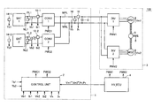
- FIG. 1 is a schematic configuration diagram showing a substantial part of a vehicle including a power supply system in accordance with a first embodiment of the present invention.
- FIG. 2 is a schematic configuration diagram of a converter in accordance with the first embodiment of the present invention.
- FIGS. 3A and 3B are views for illustrating a circulation current caused between power storage units when voltage conversion operation is started.
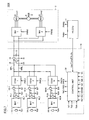
- FIG. 4 is a view showing a control block for controlling the converter in accordance with the first embodiment of the present invention.
- FIG. 5 is a view for illustrating an example of a method of determining control gains in current feedback units.
- FIG. 6 is a view showing a control block for controlling a converter in accordance with a variation of the first embodiment of the present invention.
- FIG. 7 is a schematic configuration diagram showing a substantial part of a vehicle including a power supply system in accordance with a second embodiment of the present invention.
- FIG. 8 is a view showing a control block for controlling a converter in accordance with the second embodiment of the present invention.
- FIG. 9 is a view showing a control block for controlling a converter in accordance with a variation of the second embodiment of the present invention.
- the first embodiment illustrates a case where a drive force generation unit 3 generating drive force for vehicle 100 is used as an example of a load device.
- Drive force generation unit 3 receives electric power from power supply system 1 to generate drive force, and supplies the drive force to wheels (not shown) of vehicle 100 , causing vehicle 100 to run.
- power supply system 1 having two power storage units as an example of a plurality of power storage units will be described.
- Power supply system 1 supplies and receives DC power to and from drive force generation unit 3 through a main positive bus line MPL and a main negative bus line MNL.
- Drive force generation unit 3 includes a first inverter INV 1 , a second inverter INV 2 , a first motor-generator MG 1 , and a second motor-generator MG 2 , and generates drive force in response to switching commands PWM 1 , PWM 2 from a HV_ECU (Hybrid Vehicle Electronic Control Unit) 4 .
- HV_ECU Hybrid Vehicle Electronic Control Unit
- Inverters INV 1 , INV 2 are connected in parallel to main positive bus line MPL and main negative bus line MNL, and supply and receive electric power to and from power supply system 1 .
- inverters INV 1 , INV 2 convert DC power received through main positive bus line MPL and main negative bus line MN 1 into alternate current (AC) power, and supply the AC power to motor-generators MG 1 , MG 2 , respectively.
- inverters INV 1 , INV 2 may be configured to convert AC power, generated by motor-generators MG 1 , MG 2 receiving kinetic energy of vehicle 100 during regenerative braking of vehicle 100 or the like, into DC power and supply the DC power to power supply system 1 as regenerative power.
- inverters INV 1 , INV 2 are formed of a bridge circuit including switching elements for three phases, and generate three-phase AC power by performing switching (circuit opening/closing) operation in response to respective switching commands PWM 1 , PWM 2 received from HV_ECU 4 .
- Motor-generators MG 1 , MG 2 are configured to be capable of generating rotational drive force by receiving AC power supplied from inverters INV 1 , INV 2 , respectively, and generating AC power by receiving external rotational drive force.
- motor-generators MG 1 , MG 2 are a three-phase AC electric rotating machine including a rotor having permanent magnets embedded therein.
- Motor-generators MG 1 , MG 2 are coupled to a motive power transfer mechanism 6 to transfer the generated drive force to the wheels (not shown) via a drive shaft 8 .
- motor-generators MG 1 , MG 2 are also coupled to an engine (not shown) via motive power transfer mechanism 6 or drive shaft 8 . Then, HV_ECU 4 performs control to obtain an optimal ratio between the drive force generated by the engine and the drive force generated by motor-generators MG 1 , MG 2 . If drive force generation unit 3 is applied to such a hybrid vehicle, motor-generator MG 1 may serve exclusively as an electric motor, and motor-generator MG 2 may serve exclusively as a generator.
- HV_ECU 4 executes a program stored in advance to calculate torque reference values and rotation speed reference values of motor-generators MG 1 , MG 2 , based on a signal transmitted from each sensor (not shown), a running situation, variation in an accelerator pedal position, a stored map, and the like. Then, HV_ECU 4 generates switching commands PWM 1 , PWM 2 and supplies the commands to drive force generation unit 3 such that generated torques and rotation speeds of motor-generators MG 1 , MG 2 match the calculated torque reference values and rotation speed reference values.
- HV_ECU 4 obtains counter electromotive voltage values Vm 1 , Vm 2 generated in motor-generators MG 1 , MG 2 , respectively, based on the calculated torque reference values and rotation speed reference values, or torque actual values and rotation speed actual values detected by various sensors (not shown), and outputs to power supply system 1 required voltage values Vm 1 *, Vm 2 * determined based on counter electromotive voltage values Vm 1 , Vm 2 .
- HV_ECU 4 determines voltage values higher than counter electromotive voltage values Vm 1 , Vm 2 as required voltage values Vm 1 *, Vm 2 * such that power supply system 1 can supply electric power to motor-generators MG 1 , MG 2 .
- HV_ECU 4 obtains electric power actual values P 1 , P 2 based on the products of the torque reference values and the rotation speed reference values, or the products of the torque actual values and the rotation speed actual values, and outputs electric power actual values P 1 , P 2 to power supply system 1 . It is to be noted that HV_ECU 4 informs power supply system 1 of the electric power supply/reception state in drive force generation unit 3 by changing the signs of electric power actual values P 1 , P 2 , for example, such that electric power consumption is represented by a positive value and electric power generation is represented by a negative value.
- power supply system 1 includes a smoothing capacitor C, a supply current value detection unit 16 , a supply voltage value detection unit 18 , a first converter CONV 1 , a second converter CONV 2 , a first power storage unit BAT 1 , a second power storage unit BAT 2 , battery current value detection units 10 - 1 , 10 - 2 , battery voltage value detection units 12 - 1 , 12 - 2 , battery temperature detection units 14 - 1 , 14 - 2 , and a control unit 2 .
- Smoothing capacitor C is connected between main positive bus line MPL and main negative bus line MNL, and reduces a fluctuation component contained in electric power supplied from converters CONV 1 , CONV 2 .
- Supply current value detection unit 16 is disposed in main positive bus line MPL in series, detects a supply current value Ih of electric power supplied to drive force generation unit 3 , and outputs the detection result to control unit 2 .
- Supply voltage value detection unit 18 is connected between main positive bus line MPL and main negative bus line MNL, detects a supply voltage value Vh of the electric power supplied to drive force generation unit 3 , and outputs the detection result to control unit 2 .
- Converters CONV 1 , CONV 2 are connected in parallel to main positive bus line MPL and main negative bus line MNL, and perform voltage conversion operation between corresponding power storage units BAT 1 , BAT 2 and main positive bus line MPL and main negative bus line MNL. More specifically, converters CONV 1 , CONV 2 boost discharge power from power storage units BAT 1 , BAT 2 up to a reference voltage value, respectively, to generate supply power.
- converters CONV 1 , CONV 2 are configured to include a chopper circuit, and their voltage conversion capabilities (such as allowable conversion power, an allowable conversion current value, and a voltage conversion possible range) are designed in accordance with battery capacities of power storage units BAT 1 , BAT 2 , respectively. Specifically, capacity of an inductor, a rated current value of a transistor, and the like are optimized.
- Power storage units BAT 1 , BAT 2 are connected in parallel to main positive bus line MPL and main negative bus line MNL through converters CONV 1 , CONV 2 , respectively.
- power storage units BAT 1 , BAT 2 are implemented by a rechargeable battery configured to be chargeable/dischargeable, such as a nickel hydride battery or a lithium ion battery.
- power storage units BAT 1 , BAT 2 have battery capacities different from each other.
- Battery current value detection units 10 - 1 , 10 - 2 are disposed in power lines connecting power storage units BAT 1 , BAT 2 to converters CONV 1 , CONV 2 , respectively, detect battery current values Ib 1 , Ib 2 related to input/output of power storage units BAT 1 , BAT 2 , respectively, and output the detection result to control unit 2 .
- Battery voltage value detection units 12 - 1 , 12 - 2 are connected between power lines connecting power storage units BAT 1 , BAT 2 to converters CONV 1 , CONV 2 , respectively, detect battery voltage values Vb 1 , Vb 2 of power storage units BAT 1 , BAT 2 , respectively, and output the detection result to control unit 2 .
- Battery temperature detection units 14 - 1 , 14 - 2 are arranged in the proximity of battery cells or the like constituting power storage units BAT 1 , BAT 2 , respectively, detect battery temperatures Tb 1 , Tb 2 representing internal temperatures of power storage units BAT 1 , BAT 2 , respectively, and output the detection result to control unit 2 . It is to be noted that battery temperature detection units 14 - 1 , 14 - 2 may also be configured to output representative values obtained for example by averaging processing, based on the result of detection by a plurality of detection elements arranged in correspondence with a plurality of battery cells constituting power storage units BAT 1 , BAT 2 , respectively.
- Control unit 2 generates switching commands PWC 1 , PWC 2 in accordance with a control structure described later, based on required voltage values Vm 1 *, Vm 2 * and electric power actual values P 1 , P 2 received from HV_ECU 4 , supply current value Ih received from supply current value detection unit 16 , supply voltage value Vh received from supply voltage value detection unit 18 , battery current values Ib 1 , Ib 2 received from battery current value detection units 10 - 1 , 10 - 2 , battery voltage values Vb 1 , Vb 2 received from battery voltage value detection units 12 - 1 , 12 - 2 , and battery temperatures Tb 1 , Tb 2 received from battery temperature detection units 14 - 1 , 14 - 2 , respectively, and controls the voltage conversion operation of converters CONV 1 , CONV 2 , respectively.
- control unit 2 generates duty commands Ton 1 , Ton 2 by a control system including a voltage feedback unit (main loop) setting the voltage conversion operation such that supply voltage value Vh, which is one of process values, matches a reference voltage value Vh*, and two current feedback units (minor loops) causing the voltage conversion operation to be performed such that battery current values Ib 1 , Ib 2 match current reference values Ib 1 *, Ib 2 *, respectively.
- reference voltage value Vh* is determined in accordance with required voltage values Vm 1 *, Vm 2 * received from HV_ECU 4 .
- the voltage feedback unit and the current feedback units constitute cascade control, and current reference values Ib 1 *, Ib 2 * are each determined by the result of computation from the voltage feedback unit.
- These two current feedback units are each configured to include a proportional element (P) and an integral element (I).
- a proportional gain Kp and an integral gain Ti which are control gains of the elements, are determined such that, in each of the current feedback units, it takes substantially the same amount of time from when a standard reference value (current reference value) is supplied to each current feedback unit to when a battery current value generated by the voltage conversion operation in the corresponding one of converters CONV 1 , CONV 2 reaches a standard output value.
- proportional gain Kp and integral gain Ti serving as the control gains of the elements are determined such that a transfer function including one of the current feedback units and corresponding converter CONV 1 substantially matches a transfer function including the other of the current feedback units and corresponding converter CONV 2 , with respect to delay elements.
- control system described above is configured to include voltage feedforward units adding values corresponding to ratios between reference voltage value Vh* and battery voltage values Vb 1 , Vb 2 of power storage units BAT 1 , BAT 2 , respectively (voltage conversion ratios).
- control gains in the two current feedback units controlling battery current values Ib 1 , Ib 2 of power storage units BAT 1 , BAT 2 , respectively, are determined including response characteristics (transfer functions) of converters CONV 1 , CONV 2 that are subject processes, an unwanted circulation current can be suppressed even if converters CONV 1 , CONV 2 have voltage conversion capabilities different from each other.
- drive force generation unit 3 corresponds to the “load device”
- main positive bus line MPL and main negative bus line MNL correspond to the “power line”
- converters CONV 1 , CONV 2 correspond to the “plurality of voltage conversion units.”
- battery current value detection units 10 - 1 , 10 - 2 correspond to the “battery current value detection unit”
- supply voltage value detection unit 18 corresponds to the “supply voltage value detection unit”
- battery voltage value detection units 12 - 1 , 12 - 2 correspond to the “battery voltage value detection unit”.
- Converter CONV 1 includes a chopper circuit 40 - 1 and a smoothing capacitor C 1 .
- Chopper circuit 40 - 1 can supply electric power bidirectionally. Specifically, chopper circuit 40 - 1 can boost discharge power from power storage unit BAT 1 in response to switching command PWC 1 from control unit 2 ( FIG. 1 ) to supply the boosted discharge power to drive force generation unit 3 ( FIG. 1 ), and can buck regenerative power received from drive force generation unit 3 to supply the bucked regenerative power to power storage unit BAT 1 .
- Chopper circuit 40 - 1 includes a positive bus line LN 1 A, a negative bus line LN 1 C, a line LN 1 B, transistors Q 1 A, Q 1 B serving as switching elements, diodes D 1 A, D 1 B, and an inductor L 1 .
- Positive bus line LN 1 A has one end connected to a collector of transistor Q 1 A and the other end connected to main positive bus line MPL.
- Negative bus line LN 1 C has one end connected to the negative side of power storage unit BAT 1 and the other end connected to main negative bus line MNL.
- Transistors Q 1 A and Q 1 B are connected in series between positive bus line LN 1 A and negative bus line LN 1 C.
- the collector of transistor Q 1 A is connected to positive bus line LN 1 A
- an emitter of transistor Q 1 B is connected to negative bus line LN 1 C.
- Diodes D 1 A, D 1 B allowing current to flow from the emitter side to the collector side are connected between the collector and the emitter of transistors Q 1 A, Q 1 B, respectively.
- inductor L 1 is connected to a connection point of transistor Q 1 A and transistor Q 1 B.
- Line LN 1 B has one end connected to the positive side of power storage unit BAT 1 and the other end connected to inductor L 1 .
- Smoothing capacitor C 1 is connected between line LN 1 B and negative bus line LN 1 C, and reduces AC component contained in DC voltage between line LN 1 B and negative bus line LN 1 C.
- control unit 2 maintains transistor Q 1 A in an ON state, and turns on/off transistor Q 1 B at a prescribed duty ratio.
- a discharge current flows from power storage unit BAT 1 to main positive bus line MPL, sequentially through line LN 1 B, inductor L 1 , transistor Q 1 A, and positive bus line LN 1 A.
- a pump current flows from power storage unit BAT 1 , sequentially through line LN 1 B, inductor L 1 , transistor Q 1 B, and negative bus line LN 1 C.
- Inductor L 1 accumulates electromagnetic energy by means of the pump current.
- inductor L 1 superimposes the accumulated electromagnetic energy onto the discharge current.
- an average voltage of DC power supplied from converter CONV 1 to main positive bus line MPL and main negative bus line MNL is boosted by a voltage corresponding to the electromagnetic energy accumulated in inductor L 1 in accordance with the duty ratio.
- converter CONV 2 Since the configuration and the operation of converter CONV 2 are also similar to those of converter CONV 1 described above, the detailed description thereof will not be repeated.
- the voltage conversion (boosting) capabilities of converters CONV 1 , CONV 2 are determined in accordance with electromagnetic energies stored in inductors L 1 , L 2 by a switching operation. Accordingly, amounts of inductors L 1 , L 2 (inductances) and a switching period are optimally designed in accordance with the battery capacities of power storage units BAT 1 , BAT 2 . Further, allowable current values flowing through transistors Q 1 A, Q 1 B, Q 2 A, Q 2 B are also optimally designed in accordance with the battery capacities (or charge/discharge electric powers) of power storage units BAT 1 , BAT 2 .
- the response characteristic referred to herein has a generic meaning including a temporal change in process values (such as battery current values Ib 1 , Ib 2 and supply voltage value Vh) that occurs as a result of the voltage conversion operation of converters CONV 1 , CONV 2 when a standard command is applied to converters CONV 1 , CONV 2 that are the subject processes.
- FIGS. 3A and 3B a circulation current caused between power storage units BAT 1 and BAT 2 when the voltage conversion operation is started will be described.
- FIG. 3A shows temporal changes in output voltage values Vout 1 , Vout 2 from converters CONV 1 , CONV 2 immediately after the start of the voltage conversion operations.
- FIG. 3B shows an outline of the circulation current caused between power storage units BAT 1 and BAT 2 .
- control unit 2 When control unit 2 receives an ignition-on signal (not shown) for example, it starts generating duty commands Ton 1 , Ton 2 according to a predetermined control computing equation. As described above, when inductors L 1 , L 2 contained in converters CONV 1 , CONV 2 have different amounts, they have different electromagnetic energies stored in each switching cycle to be used for the voltage conversion operation (boosting). Therefore, in a transition state, as shown in FIG. 3A , the temporal change in output voltage value Vout 1 of converter CONV 1 does not match that in output voltage value Vout 2 of converter CONV 2 .
- a voltage difference ⁇ V may occur transiently between the output voltages due to a difference in response characteristics (rise times) of output voltage values Vout 1 , Vout 2 of converters CONV 1 , CONV 2 .
- the control gains in the two current feedback units related to battery current values Ib 1 , Ib 2 are determined to suppress such circulation current Ic, taking the response characteristics of converters CONV 1 , CONV 2 into consideration.
- such circulation current Ic is suppressed by setting such that time taken from when a standard reference value (current reference value) is supplied to one of the current feedback units to when battery current value Ib 1 generated by the voltage conversion operation in corresponding converter CONV 1 reaches a standard output value (i.e., response time) is substantially identical to time taken from when the standard reference value (current reference value) is supplied to the other of the current feedback units to when battery current value Ib 2 generated by the voltage conversion operation in corresponding converter CONV 2 reaches the standard output value.
- a standard reference value current reference value
- response time is substantially identical to time taken from when the standard reference value (current reference value) is supplied to the other of the current feedback units to when battery current value Ib 2 generated by the voltage conversion operation in corresponding converter CONV 2 reaches the standard output value.
- Control block 200 includes a voltage feedback unit 50 , division units 56 - 1 , 56 - 2 , current feedback units 60 - 1 , 60 - 2 , voltage feedforward units 70 - 1 , 70 - 2 , and modulation units (MOD) 58 - 1 , 58 - 2 .
- MOD modulation units
- Voltage feedback unit 50 receives reference voltage value Vh* and supply voltage value Vh, and supplies a control output corresponding to a voltage deviation therebetween such that supply voltage value Vh matches reference voltage value Vh*.
- voltage feedback unit 50 generates an electric power deviation by multiplying the voltage deviation by a prescribed constant, and outputs an electric power reference value Pb*, which is a reference value of the supply power of converters CONV 1 , CONV 2 , based on the generated electric power deviation.
- reference voltage value Vh* is determined so as not fall below the maximum battery voltage value of battery voltage values Vb 1 , Vb 2 , i.e., such that the minimum value of reference voltage value Vh* is maintained at the maximum battery voltage value, to suppress a circulation current caused immediately after the start of the control due to a difference in the battery voltages of power storage units BAT 1 , BAT 2 .
- Voltage feedback unit 50 includes a subtraction unit 52 and a proportional and integral unit (PI) 54 .
- Subtraction unit 52 computes the voltage deviation based on a difference between reference voltage value Vh* and supply voltage value Vh, and outputs the voltage deviation to proportional and integral unit 54 .
- Proportional and integral unit 54 is configured to include at least a proportional element (P) and an integral element (I), and outputs to division units 56 - 1 , 56 - 2 the control output (electric power reference value Pb*) corresponding to the input voltage deviation.
- Division units 56 - 1 , 56 - 2 receive electric power reference value Pb* and divide electric power reference value Pb* by battery voltage values Vb 1 , Vb 2 of power storage units BAT 1 , BAT 2 to calculate current reference values Ib 1 *, Ib 2 *, respectively. Then, division units 56 - 1 , 56 - 2 output the calculated current reference values Ib 1 *, Ib 2 * to current feedback units 60 - 1 , 60 - 2 , respectively.
- Current feedback unit 60 - 1 receives current reference values Ib 1 * and battery current value Ib 1 , and supplies a control output corresponding to a current deviation therebetween such that battery current value Ib 1 matches current reference values Ib 1 *.
- current feedback unit 60 - 2 receives current reference values Ib 2 * and battery current value Ib 2 , and supplies a control output corresponding to a current deviation therebetween such that battery current value Ib 2 matches current reference values Ib 2 *.
- current feedback unit 60 - 1 includes a subtraction unit 62 - 1 , a proportional element 64 - 1 , an integral element 66 - 1 , and an addition unit 68 - 1 .
- Subtraction unit 62 - 1 computes the current deviation based on a difference between current reference values Ib 1 * and battery current value Ib 1 , and supplies an output to proportional element 64 - 1 .
- Proportional element 64 - 1 has a proportional gain Kp 1 , multiples the output received from subtraction unit 62 - 1 by proportional gain Kp 1 , and supplies an output to integral element 66 - 1 and addition unit 68 - 1 .
- Integral element 66 - 1 has an integral gain (integral time or reset time) Ti 1 , integrates the output received from proportional element 64 - 1 with respect to time, and supplies an output to addition unit 68 - 1 .
- Addition unit 68 - 1 adds the two outputs received from proportional element 64 - 1 and integral element 66 - 1 to supply an output to voltage feedforward unit 70 - 1 . That is, the control output supplied from current feedback unit 60 - 1 is represented by Kp 1 ⁇ (1+1/sTi 1 ) ⁇ (Ib 1 * ⁇ Ib 1 ), where “s” indicates the Laplace variable.
- current feedback unit 60 - 2 includes a subtraction unit 62 - 2 , a proportional element 64 - 2 , an integral element 66 - 2 , and an addition unit 68 - 2 . Since current feedback unit 60 - 2 is similar to current feedback unit 60 - 1 described above except that proportional element 64 - 2 has a proportional gain Kp 2 and integral element 66 - 2 has an integral gain Ti 2 , the detailed description thereof will not be repeated.
- Voltage feedforward unit 70 - 1 inverts the sign of the control output received from current feedback unit 60 - 1 , and then adds battery voltage value Vb 1 /reference voltage value Vh* and outputs duty command Ton 1 .
- voltage feedforward unit 70 - 2 inverts the sign of the control output received from current feedback unit 60 - 2 , and then adds battery voltage value Vb 2 /reference voltage value Vh* and outputs duty command Ton 2 .
- Battery voltage value Vb 1 /reference voltage value Vh* and battery voltage value Vb 2 /reference voltage value Vh* correspond to the reciprocals of theoretical boost ratios in converters CONV 1 , CONV 2 , respectively.
- voltage feedforward unit 70 - 1 includes a division unit 74 - 1 and a subtraction unit 72 - 1 .
- Division unit 74 - 1 divides battery voltage value Vb 1 of power storage unit BAT 1 by reference voltage value Vh*, and outputs the division result to subtraction unit 72 - 1 .
- Subtraction unit 72 - 1 inverts the sign of the control output received from current feedback unit 60 - 1 , adds the division result received from division unit 74 - 1 , and supplies an output to modulation unit 58 - 1 .
- voltage feedforward unit 70 - 2 includes a division unit 74 - 2 and a subtraction unit 72 - 2 . Since the operation of voltage feedforward unit 70 - 2 is similar to that of voltage feedforward unit 70 - 1 , the detailed description thereof will not be repeated.
- Modulation unit 58 - 1 compares duty command Ton 1 received from voltage feedforward unit 70 - 1 with a carrier wave generated by an oscillation unit not shown, and generates switching command PWC 1 .
- modulation unit 58 - 2 compares duty command Ton 2 received from voltage feedforward unit 70 - 2 with the carrier wave generated by the oscillation unit not shown, and generates switching command PWC 2 .
- Duty commands Ton 1 , Ton 2 are control commands defining on-duty of transistors Q 1 B, Q 2 B ( FIG. 2 ) of converters CONV 1 , CONV 2 , respectively, determining boost ratios of converters CONV 1 , CONV 2 .
- control block 200 shown in FIG. 4 can also be implemented by configuring control unit 2 to include a circuit corresponding to each block, in many cases, control block 200 is implemented by control unit 2 executing a process routine in accordance with a preset program.
- voltage feedback unit 50 commonly used to generate duty commands Ton 1 , Ton 2 , it is not possible to set a control gain separately for each of converters CONV 1 , CONV 2 . Further, although voltage feedforward units 70 - 1 , 70 - 2 can determine initial values at the start of the control, they give no affect to a transient operation.
- control gains can be determined taking only current feedback units 60 - 1 , 60 - 2 and converters CONV 1 , CONV 2 into consideration.
- control models 76 - 1 , 76 - 2 having duty commands Ton 1 , Ton 2 as inputs and battery current values Ib 1 , Ib 2 as outputs, provided corresponding to converters CONV 1 , CONV 2 have transfer functions P 1 ( s ), P 2 ( s ), respectively, control systems taking current feedback units 60 - 1 , 60 - 2 and converters CONV 1 , CONV 2 into consideration, respectively, are represented as shown in FIG. 5 .
- control models 76 - 1 , 76 - 2 can be modeled based on physical constants of the elements of chopper circuits 40 - 1 , 40 - 2 ( FIG. 2 ), switching cycles of modulation units 58 - 1 , 58 - 2 ( FIG. 3 ), delays in detection in battery current value detection units 10 - 1 , 10 - 2 ( FIG. 1 ), and the like.
- control gains are determined such that transfer functions G 1 ( s ), G 2 ( s ) described above substantially match with each other, with respect to delay elements. Specifically, the control gains are determined to satisfy the following relationship: G 1( s ) ⁇ G 2( s ), that is, Kp 1 ⁇ (1+1 /sTi 1) ⁇ P 1( s ) ⁇ Kp 2 ⁇ (1+1 /sTi 2) ⁇ P 2( s ),
- control gains are determined such that terms related to a delay element 1/s (and/or 1/s 2 , . . . , 1/s n ) have coefficients substantially identical to each other.
- conversion constant ⁇ is a value for compensating for (or standardizing) a difference in rated values of battery current values Ib 1 , Ib 2 flowing from power storage units BAT 1 , BAT 2 to converters CONV 1 , CONV 2 , and corresponds to a ratio between the rated values of battery current values Ib 1 , Ib 2 .
- control gains are determined to satisfy the following relationship: Kp 1 ⁇ (1+1 /sTi 1) ⁇ Ps 1( s ) ⁇ Kp 2 ⁇ (1+1 /sTi 2) ⁇ Ps 2( s ).
- time taken from when a step input (100% of the rated value) as a standard reference value is supplied to input X 1 ( s ) to when an output value (battery current value Ib 1 ) of transfer function G 1 ( s ) in the time domain reaches a standard output value (for example, 63% of the rated value) can substantially match time taken from when the step input as the standard reference value is supplied to input X 2 ( s ) to when an output value (battery current value Ib 2 ) of transfer function G 2 ( s ) in the time domain reaches the standard output value.
- control gains may be determined so as to substantially match closed loop transfer functions.
- control gains in current feedback units are determined such that one transfer function including one of the current feedback units and a corresponding converter substantially matches the other transfer function, with respect to delay elements.
- the current feedback units determining response characteristics of the converters during transition are implemented to compensate for a difference in the response characteristics of the converters, and thus response characteristics of output voltages of the converters substantially match with each other. Therefore, generation of a voltage difference between the converters during transition such as immediately after the start of control can be avoided, suppressing a circulation current between power storage units flowing through the converters. Consequently, a power supply system that suppresses an unwanted circulation current caused between a plurality of converters having voltage conversion capabilities different from each other and avoids damage to power storage units, and a vehicle including the power supply system can be implemented.
- Control block 202 includes voltage feedback units 80 - 1 , 80 - 2 arranged instead of voltage feedback unit 50 , division units 56 - 1 , 56 - 2 , and current feedback units 60 - 1 , 60 - 2 in control block 200 shown in FIG. 4 .
- Voltage feedback units 80 - 1 , 80 - 2 each receive reference voltage value Vh* and supply voltage value Vh, and supply a control output corresponding to a voltage deviation therebetween such that supply voltage value Vh matches reference voltage value Vh*.
- voltage feedback unit 80 - 1 includes a subtraction unit 82 - 1 , a proportional element 84 - 1 , an integral element 86 - 1 , and an addition unit 88 - 1 .
- Subtraction unit 82 - 1 computes the voltage deviation based on a difference between reference voltage value Vh* and supply voltage value Vh, and supplies an output to proportional element 84 - 1 .
- Proportional element 84 - 1 has a proportional gain #Kp 1 , multiples the output received from subtraction unit 82 - 1 by proportional gain #Kp 1 , and supplies an output to integral element 86 - 1 and addition unit 88 - 1 .
- Integral element 86 - 1 has an integral gain (integral time or reset time) #Ti 1 , integrates the output received from proportional element 84 - 1 with respect to time, and supplies an output to addition unit 88 - 1 .
- Addition unit 88 - 1 adds the two outputs received from proportional element 84 - 1 and integral element 86 - 1 to supply an output to voltage feedforward unit 70 - 1 . That is, the control output supplied from voltage feedback unit 80 - 1 is represented by #Kp 1 ⁇ (1+1/s#Ti 1 ) ⁇ (Vh* ⁇ Vh), where “s” indicates the Laplace variable.
- voltage feedback unit 80 - 2 includes a subtraction unit 82 - 2 , a proportional element 84 - 2 , an integral element 86 - 2 , and an addition unit 88 - 2 . Since voltage feedback unit 80 - 2 is similar to voltage feedback unit 80 - 1 described above except that proportional element 84 - 2 has a proportional gain #Kp 2 and integral element 86 - 2 has an integral gain #Ti 2 , the detailed description thereof will not be repeated.
- control gains in voltage feedback units 80 - 1 , 80 - 2 are determined as in the first embodiment of the present invention described above. That is, the control gains in voltage feedback units 80 - 1 , 80 - 2 are determined such that one transfer function including voltage feedback unit 80 - 1 and converter CONV 1 substantially matches the other transfer function including voltage feedback unit 80 - 2 and converter CONV 2 , with respect to delay elements.
- transfer functions #P 1 ( s ), #P 2 ( s ) modeling converters CONV 1 , CONV 2 are determined to have duty commands Ton 1 , Ton 2 as inputs, respectively, and supply voltage value Vh as an output.
- a control structure in addition to the effect obtained by the first embodiment of the present invention, can be simplified as it is configured by single feedback loops.
- the present invention is applicable to a power supply system having three or more power storage units, in addition to the power supply system having two power storage units described above.
- a vehicle 100 # including a power supply system 1 # in accordance with a second embodiment of the present invention will be described. Since vehicle 100 # includes power supply system 1 # arranged instead of power supply system 1 in vehicle 100 shown in FIG. 1 , the detailed description of drive force generation unit 3 will not be repeated. In the second embodiment of the present invention, power supply system 1 # including N power storage units will be described.
- Power supply system 1 # includes converters CONV 1 , CONV 2 , . . . , CONVN, power storage units BAT 1 , BAT 2 , . . . , BATN, battery current value detection units 10 - 1 , 10 - 2 , . . . , 10 -N, battery voltage value detection units 12 - 1 , 12 - 2 , . . . , 12 -N, and battery temperature detection units 14 - 1 , 14 - 2 , . . .
- power supply system 1 # includes a control unit 2 # arranged instead of control unit 2 in power supply system 1 shown in FIG. 1 .
- Converters CONV 1 to CONVN are connected in parallel to main positive bus line MPL and main negative bus line MNL, and perform voltage conversion operation between respective power storage units BAT 1 to BATN and main positive bus line MPL and main negative bus line MNL.
- Power storage units BAT 1 to BATN are connected in parallel to main positive bus line MPL and main negative bus line MNL through converters CONV 1 to CONVN, respectively.
- at least one of power storage units BAT 1 to BATN has a battery capacity different from that of other power storage units.
- Battery current value detection units 10 - 1 to 10 -N, battery voltage value detection units 12 - 1 to 12 -N, and battery temperature detection units 14 - 1 to 14 -N are arranged in correspondence with power storage units BAT 1 to BATN, respectively.
- Control unit # 2 generates duty commands Ton 1 to TonN by a control system including a voltage feedback unit (main loop) setting the voltage conversion operation such that supply voltage value Vh, which is one of process values, matches reference voltage value Vh*, and N current feedback units (minor loops) causing the voltage conversion operation to be performed such that battery current values Ib 1 to IbN match current reference values Ib 1 * to IbN*, respectively.
- reference voltage value Vh* is determined in accordance with required voltage values Vm 1 *, Vm 2 * received from HV_ECU 4 .
- the voltage feedback unit and the current feedback units constitute cascade control, and current reference values Ib 1 * to IbN* are each determined by the result of computation from the voltage feedback unit.
- N current feedback units are each configured to include a proportional element (P) and an integral element (I).
- Proportional gain Kp and integral gain Ti which are control gains of the elements, are determined such that, in each of the current feedback units, it takes substantially the same amount of time from when a standard reference value (current reference value) is supplied to each current feedback unit to when a battery current value generated by the voltage conversion operation in the corresponding one of converters CONV 1 to CONVN reaches a standard output value.
- proportional gain Kp and integral gain Ti serving as control gains of the elements are determined such that transfer functions including respective current feedback units and respective corresponding converters CONV 1 to CONVN substantially match with one another, with respect to delay elements.
- control system described above is configured to include voltage feedforward units adding values corresponding to ratios between reference voltage value Vh* and battery voltage values Vb 1 to VbN of power storage units BAT 1 to BATN, respectively (voltage conversion ratios).
- vehicle 100 # is the same as that in the first embodiment of the present invention described above, and thus the detailed description thereof will not be repeated.
- drive force generation unit 3 corresponds to the “load device”
- main positive bus line MPL and main negative bus line MNL correspond to the “power line”
- converters CONV 1 to CONVN correspond to the “plurality of voltage conversion units.”
- battery current value detection units 10 - 1 to 10 -N implement the “battery current value detection unit”
- supply voltage value detection unit 18 implements the “supply voltage value detection unit”
- battery voltage value detection units 12 - 1 to 12 -N implement the “battery voltage value detection unit”.
- Control block 200 # is an extended version of control block 200 shown in FIG. 4 , and includes division units 56 - 1 to 56 -N, current feedback units 60 - 1 to 60 -N, voltage feedforward units 70 - 1 to 70 -N, and modulation units (MOD) 58 - 1 to 58 -N, arranged instead of division units 56 - 1 , 56 - 2 , current feedback units 60 - 1 , 60 - 2 , voltage feedforward units 70 - 1 , 70 - 2 , and modulation units (MOD) 58 - 1 , 58 - 2 in control block 200 , respectively.
- control block 200 # is the same as control block 200 , and thus the detailed description thereof will not be repeated.
- control gains in current feedback units 60 - 1 to 60 -N are each determined as in the first embodiment of the present invention described above. That is, the control gains in current feedback units 60 - 1 to 60 -N are determined such that transfer functions including the control gains of respective current feedback units 60 - 1 to 60 -N and respective corresponding converters CONV 1 to CONVN substantially match with one another, with respect to delay elements.
- control block 200 # is the same as that in the first embodiment of the present invention described above, and thus the detailed description thereof will not be repeated.
- the effect similar to that in the first embodiment of the present invention can be obtained even when the power supply system includes three or more converters and power storage units.
- the number of converters and power storage units can be designed relatively freely in accordance with a required electric power value of the load device. Therefore, a power supply system capable of supplying electric power to load devices of various sizes and types and a vehicle including the power supply system can be implemented.
- Control block 202 # is an extended version of control block 202 shown in FIG. 6 , and includes voltage feedback units 80 - 1 to 80 -N, voltage feedforward units 70 - 1 to 70 -N, and modulation units (MOD) 58 - 1 to 58 -N, arranged instead of voltage feedback units 80 - 1 , 80 - 2 , voltage feedforward units 70 - 1 , 70 - 2 , and modulation units (MOD) 58 - 1 , 58 - 2 in control block 202 , respectively.
- control block 202 # is the same as control block 202 , and thus the detailed description thereof will not be repeated.
- control gains are each determined as in the variation of the first embodiment of the present invention described above. That is, the control gains in voltage feedback units 80 - 1 to 80 -N are determined such that transfer functions including the control gains of respective voltage feedback units 80 - 1 to 80 -N and respective corresponding converters CONV 1 to CONVN substantially match with one another, with respect to delay elements.
- a control structure in addition to the effect obtained by the second embodiment of the present invention, can be simplified as it is configured by single feedback loops.
- the number of motor-generators is not limited.
- the load device is not limited to a drive force generation unit generating drive force for a vehicle, and the present invention is applicable to a device only consuming electric power as well as to a device capable of consuming and generating electric power.
Abstract
Description
G1(s)=Y1(s)/X1(s)=Kp1×(1+1/sTi1)×P1(s),
G2(s)=Y2(s)/X2(s)=Kp2×(1+1/sTi2)×P2(s).
G1(s)≈α×G2(s), that is,
Kp1×(1+1/sTi1)×P1(s)≈α×Kp2×(1+1/sTi2)×P2(s),
Kp1×(1+1/sTi1)×Ps1(s)≈Kp2×(1+1/sTi2)×Ps2(s).
Claims (20)
Applications Claiming Priority (3)
| Application Number | Priority Date | Filing Date | Title |
|---|---|---|---|
| JP2006119300A JP4379430B2 (en) | 2006-04-24 | 2006-04-24 | Power supply system and vehicle |
| JP2006-119300 | 2006-04-24 | ||
| PCT/JP2007/058687 WO2007125840A1 (en) | 2006-04-24 | 2007-04-16 | Power supply system and vehicle |
Publications (2)
| Publication Number | Publication Date |
|---|---|
| US20090273235A1 US20090273235A1 (en) | 2009-11-05 |
| US7847432B2 true US7847432B2 (en) | 2010-12-07 |
Family
ID=38655366
Family Applications (1)
| Application Number | Title | Priority Date | Filing Date |
|---|---|---|---|
| US12/225,694 Active 2027-08-10 US7847432B2 (en) | 2006-04-24 | 2007-04-16 | Power supply system and vehicle |
Country Status (4)
| Country | Link |
|---|---|
| US (1) | US7847432B2 (en) |
| JP (1) | JP4379430B2 (en) |
| CN (1) | CN101427453B (en) |
| WO (1) | WO2007125840A1 (en) |
Cited By (9)
| Publication number | Priority date | Publication date | Assignee | Title |
|---|---|---|---|---|
| US20090261658A1 (en) * | 2008-04-18 | 2009-10-22 | Toyota Jidosha Kabushiki Kaisha | Power supply system, vehicle having power supply system, and control method of power supply system |
| US20100001583A1 (en) * | 2006-10-24 | 2010-01-07 | Shinji Ichikawa | Power supply system, vehicle with the same, control method of power supply system and computer-readable recording medium bearing program causing computer to execute control method of power supply system |
| US20100065351A1 (en) * | 2007-02-13 | 2010-03-18 | Toyota Jidosha Kabushiki Kaisha | Driving force generation system, vehicle using the system, and method for controlling the system |
| US20100065349A1 (en) * | 2007-01-04 | 2010-03-18 | Toyota Jidosha Kabushiki Kaisha | Power supply system and vehicle including the same, and method of controlling the same |
| US20110208383A1 (en) * | 2008-10-31 | 2011-08-25 | Masaya Yamamoto | Electric powered vehicle and control method for the same |
| US8972765B1 (en) * | 2012-04-04 | 2015-03-03 | The Boeing Company | Electrical energy management method and apparatus for multiple distribution buses and batteries |
| US20150180252A1 (en) * | 2013-12-23 | 2015-06-25 | Evtronic | Compact and modular electrical power supply unit, with multi-converters, notably for fast recharging terminals for electric vehicles |
| KR20180039919A (en) | 2016-10-11 | 2018-04-19 | 신일제약주식회사 | Fab fragment and uses thereof |
| US10020759B2 (en) | 2015-08-04 | 2018-07-10 | The Boeing Company | Parallel modular converter architecture for efficient ground electric vehicles |
Families Citing this family (23)
| Publication number | Priority date | Publication date | Assignee | Title |
|---|---|---|---|---|
| US20100096198A1 (en) * | 2008-10-20 | 2010-04-22 | Gordon Liao | Electrical Vehicle Battery Set Circuitry |
| JP2010104129A (en) * | 2008-10-22 | 2010-05-06 | Sanyo Electric Co Ltd | Power supply system, power supply side controller, and electric motor car |
| JP5359249B2 (en) * | 2008-12-18 | 2013-12-04 | 富士電機株式会社 | Uninterruptible power system |
| JP5326905B2 (en) * | 2009-07-24 | 2013-10-30 | トヨタ自動車株式会社 | Power supply system, electric vehicle including the same, and control method of power supply system |
| CN101969272B (en) * | 2010-09-21 | 2013-04-17 | 电子科技大学 | Grid-connected current control device of photovoltaic inverter |
| CN102934314B (en) * | 2011-04-25 | 2015-12-02 | 丰田自动车株式会社 | Power brick |
| US9437058B2 (en) | 2011-07-26 | 2016-09-06 | Gogoro Inc. | Dynamically limiting vehicle operation for best effort economy |
| US8901861B2 (en) * | 2011-07-26 | 2014-12-02 | Gogoro, Inc. | Thermal management of components in electric motor drive vehicles |
| TWI553999B (en) | 2011-07-26 | 2016-10-11 | 睿能創意公司 | A portable electrical energy storage device collection,charging and distrbution machne, anoperating method thereof,and a non-transitorycomputer-readable medium for storing instructions |
| EP2769449B1 (en) * | 2011-10-21 | 2020-05-13 | Schneider Electric IT Corporation | Adaptive load sharing of parallel inverters system |
| DE102011085559A1 (en) * | 2011-11-02 | 2013-05-02 | Robert Bosch Gmbh | Voltage converter with a first parallel connection |
| EP3030454B1 (en) | 2013-08-06 | 2019-06-05 | Gogoro Inc. | Adjusting electric vehicle systems based on an electrical energy storage device thermal profile |
| JP5954356B2 (en) * | 2014-05-12 | 2016-07-20 | トヨタ自動車株式会社 | Electric vehicle |
| JP6040965B2 (en) * | 2014-07-10 | 2016-12-07 | トヨタ自動車株式会社 | Power system |
| JP2016029874A (en) * | 2014-07-22 | 2016-03-03 | トヨタ自動車株式会社 | Power supply system |
| US9680332B2 (en) * | 2015-04-30 | 2017-06-13 | Delphi Technologies, Inc. | Wireless battery charger with wireless control system and method for control thereof |
| TWI668139B (en) | 2015-06-05 | 2019-08-11 | 英屬開曼群島商睿能創意公司 | A vehicle, a method of determining a particular type of load of an electric vehicle, and a non-transitory computer readable storage medium |
| US20170214251A1 (en) * | 2016-01-21 | 2017-07-27 | General Electric Company | Energy Storage Systems With Enhanced Storage and Discharge Response Allocation |
| US10131245B2 (en) * | 2016-08-16 | 2018-11-20 | Ford Global Technologies, Llc | Electrified vehicle DC power conversion with distributed control |
| JP6634041B2 (en) * | 2017-01-31 | 2020-01-22 | 株式会社Soken | Control device for power conversion system |
| JP7081959B2 (en) * | 2018-03-30 | 2022-06-07 | 本田技研工業株式会社 | Vehicle power system |
| CN108712076A (en) * | 2018-06-21 | 2018-10-26 | 哈尔滨理工大学 | A kind of fuel cell car DC/DC transformer configurations and its control method |
| DE102019125067A1 (en) * | 2019-09-18 | 2021-03-18 | Ford Global Technologies, Llc | Method for operating an on-board network of a motor vehicle |
Citations (8)
| Publication number | Priority date | Publication date | Assignee | Title |
|---|---|---|---|---|
| JPH11155233A (en) | 1997-11-25 | 1999-06-08 | Advantest Corp | Dc power supply equipment |
| JP2001197732A (en) | 2000-01-06 | 2001-07-19 | Fuji Electric Co Ltd | Control device for semiconductor power converter |
| JP2002010502A (en) | 2000-06-16 | 2002-01-11 | Sansha Electric Mfg Co Ltd | Charge and discharge device for storage battery |
| US6566846B1 (en) * | 2000-11-10 | 2003-05-20 | Marvell International, Ltd | Cascode regulator with plural outputs |
| US20030107352A1 (en) | 2001-12-06 | 2003-06-12 | Downer Scott D. | Electrical motor power management system |
| JP2003309997A (en) | 2002-04-16 | 2003-10-31 | Toyota Motor Corp | Apparatus and method for converting voltage and computer-readable recording medium recording program for making computer execute control of voltage conversion |
| JP2003324989A (en) | 2002-04-25 | 2003-11-14 | Toyoda Mach Works Ltd | Motor controller |
| JP2004015866A (en) | 2002-06-04 | 2004-01-15 | Nissan Motor Co Ltd | Method and apparatus for controlling charging/discharging |
Family Cites Families (1)
| Publication number | Priority date | Publication date | Assignee | Title |
|---|---|---|---|---|
| CN100389517C (en) * | 2002-12-16 | 2008-05-21 | 丰田自动车株式会社 | Fuel cell system having secondary cell |
-
2006
- 2006-04-24 JP JP2006119300A patent/JP4379430B2/en active Active
-
2007
- 2007-04-16 WO PCT/JP2007/058687 patent/WO2007125840A1/en active Search and Examination
- 2007-04-16 US US12/225,694 patent/US7847432B2/en active Active
- 2007-04-16 CN CN2007800146213A patent/CN101427453B/en active Active
Patent Citations (10)
| Publication number | Priority date | Publication date | Assignee | Title |
|---|---|---|---|---|
| JPH11155233A (en) | 1997-11-25 | 1999-06-08 | Advantest Corp | Dc power supply equipment |
| JP2001197732A (en) | 2000-01-06 | 2001-07-19 | Fuji Electric Co Ltd | Control device for semiconductor power converter |
| JP2002010502A (en) | 2000-06-16 | 2002-01-11 | Sansha Electric Mfg Co Ltd | Charge and discharge device for storage battery |
| US6566846B1 (en) * | 2000-11-10 | 2003-05-20 | Marvell International, Ltd | Cascode regulator with plural outputs |
| US20030107352A1 (en) | 2001-12-06 | 2003-06-12 | Downer Scott D. | Electrical motor power management system |
| JP2003209969A (en) | 2001-12-06 | 2003-07-25 | General Motors Corp <Gm> | Electric motor power supply management system |
| US6608396B2 (en) | 2001-12-06 | 2003-08-19 | General Motors Corporation | Electrical motor power management system |
| JP2003309997A (en) | 2002-04-16 | 2003-10-31 | Toyota Motor Corp | Apparatus and method for converting voltage and computer-readable recording medium recording program for making computer execute control of voltage conversion |
| JP2003324989A (en) | 2002-04-25 | 2003-11-14 | Toyoda Mach Works Ltd | Motor controller |
| JP2004015866A (en) | 2002-06-04 | 2004-01-15 | Nissan Motor Co Ltd | Method and apparatus for controlling charging/discharging |
Non-Patent Citations (1)
| Title |
|---|
| Di Napoli, Multiple-Input DC-DC Power Converter for Power-Flow Management in Hybrid Vehicles, 2002, IEEE 0-7803-7310-7/02, p. 1578-1585. * |
Cited By (15)
| Publication number | Priority date | Publication date | Assignee | Title |
|---|---|---|---|---|
| US20100001583A1 (en) * | 2006-10-24 | 2010-01-07 | Shinji Ichikawa | Power supply system, vehicle with the same, control method of power supply system and computer-readable recording medium bearing program causing computer to execute control method of power supply system |
| US7989978B2 (en) * | 2006-10-24 | 2011-08-02 | Toyota Jidosha Kabushiki Kaisha | Power supply system, vehicle with the same, control method of power supply system and computer-readable recording medium bearing program causing computer to execute control method of power supply system |
| US20100065349A1 (en) * | 2007-01-04 | 2010-03-18 | Toyota Jidosha Kabushiki Kaisha | Power supply system and vehicle including the same, and method of controlling the same |
| US7923866B2 (en) * | 2007-01-04 | 2011-04-12 | Toyota Jidosha Kabushiki Kaisha | Power supply system and vehicle including the same, and method of controlling the same |
| US20100065351A1 (en) * | 2007-02-13 | 2010-03-18 | Toyota Jidosha Kabushiki Kaisha | Driving force generation system, vehicle using the system, and method for controlling the system |
| US8053921B2 (en) * | 2007-02-13 | 2011-11-08 | Toyota Jidosha Kabushiki Kaisha | Driving force generation system, vehicle using the system, and method for controlling the system |
| US8089177B2 (en) * | 2008-04-18 | 2012-01-03 | Toyota Jidosha Kabushiki Kaisha | Power supply system, vehicle having power supply system, and control method of power supply system |
| US20090261658A1 (en) * | 2008-04-18 | 2009-10-22 | Toyota Jidosha Kabushiki Kaisha | Power supply system, vehicle having power supply system, and control method of power supply system |
| US20110208383A1 (en) * | 2008-10-31 | 2011-08-25 | Masaya Yamamoto | Electric powered vehicle and control method for the same |
| US8793041B2 (en) | 2008-10-31 | 2014-07-29 | Toyota Jidosha Kabushiki Kaisha | Electric powered vehicle and control method for the same |
| US8972765B1 (en) * | 2012-04-04 | 2015-03-03 | The Boeing Company | Electrical energy management method and apparatus for multiple distribution buses and batteries |
| US20150180252A1 (en) * | 2013-12-23 | 2015-06-25 | Evtronic | Compact and modular electrical power supply unit, with multi-converters, notably for fast recharging terminals for electric vehicles |
| US9590434B2 (en) * | 2013-12-23 | 2017-03-07 | Evtronic | Compact and modular electrical power supply unit, with multi-converters, notably for fast recharging terminals for electric vehicles |
| US10020759B2 (en) | 2015-08-04 | 2018-07-10 | The Boeing Company | Parallel modular converter architecture for efficient ground electric vehicles |
| KR20180039919A (en) | 2016-10-11 | 2018-04-19 | 신일제약주식회사 | Fab fragment and uses thereof |
Also Published As
| Publication number | Publication date |
|---|---|
| JP4379430B2 (en) | 2009-12-09 |
| JP2007295695A (en) | 2007-11-08 |
| CN101427453A (en) | 2009-05-06 |
| US20090273235A1 (en) | 2009-11-05 |
| CN101427453B (en) | 2011-11-09 |
| WO2007125840A1 (en) | 2007-11-08 |
Similar Documents
| Publication | Publication Date | Title |
|---|---|---|
| US7847432B2 (en) | Power supply system and vehicle | |
| US7750505B2 (en) | Power supply system and vehicle | |
| US7989978B2 (en) | Power supply system, vehicle with the same, control method of power supply system and computer-readable recording medium bearing program causing computer to execute control method of power supply system | |
| KR101025896B1 (en) | Power supply system, vehicle using the same, power supply system control method, and computer-readable recording medium containing program for causing computer to execute the method | |
| US8035252B2 (en) | Power supply system, vehicle with the same, temperature increase control method for power storage device and computer-readable recording medium bearing program for causing computer to execute temperature increase control of power storage device | |
| US8267207B2 (en) | Power supply system and vehicle including the same | |
| US7928603B2 (en) | Power supply system, vehicle using the same and its control method | |
| US8292009B2 (en) | Power supply device and vehicle including the same, control method for power supply device, and computer-readable recording medium having program for causing computer to execute that control method recorded thereon | |
| US8344699B2 (en) | Power supply, system having a plurality of power storage units, vehicle using the same, and its control method | |
| US7939969B2 (en) | Power supply system, vehicle with the same, temperature increase control method for power storage device and computer-readable recording medium bearing program causing computer to execute temperature increase control of power storage device | |
| US7911077B2 (en) | Power supply system, vehicle provided with the same, temperature rise control method of power storage device, and computer-readable recording medium with program recorded thereon for causing computer to execute temperature rise control of power storage device | |
| US8089177B2 (en) | Power supply system, vehicle having power supply system, and control method of power supply system | |
| US7956489B2 (en) | Power supply system and vehicle including the same | |
| US8798826B2 (en) | Power supply system, vehicle including the same, control method for power supply system, and computer-readable recording medium recording program for causing computer to execute the control method | |
| US20090314558A1 (en) | Voltage Conversion Apparatus and Vehicle Including the Same |
Legal Events
| Date | Code | Title | Description |
|---|---|---|---|
| AS | Assignment |
Owner name: TOYOTA JIDOSHA KABUSHIKI KAISHA, JAPAN Free format text: ASSIGNMENT OF ASSIGNORS INTEREST;ASSIGNOR:ICHIKAWA, SHINJI;REEL/FRAME:021622/0082 Effective date: 20080909 |
|
| STCF | Information on status: patent grant |
Free format text: PATENTED CASE |
|
| FEPP | Fee payment procedure |
Free format text: PAYOR NUMBER ASSIGNED (ORIGINAL EVENT CODE: ASPN); ENTITY STATUS OF PATENT OWNER: LARGE ENTITY |
|
| FPAY | Fee payment |
Year of fee payment: 4 |
|
| MAFP | Maintenance fee payment |
Free format text: PAYMENT OF MAINTENANCE FEE, 8TH YEAR, LARGE ENTITY (ORIGINAL EVENT CODE: M1552) Year of fee payment: 8 |
|
| AS | Assignment |
Owner name: DENSO CORPORATION, JAPAN Free format text: ASSIGNMENT OF ASSIGNORS INTEREST;ASSIGNOR:TOYOTA JIDOSHA KABUSHIKI KAISHA;REEL/FRAME:052285/0419 Effective date: 20191224 |
|
| MAFP | Maintenance fee payment |
Free format text: PAYMENT OF MAINTENANCE FEE, 12TH YEAR, LARGE ENTITY (ORIGINAL EVENT CODE: M1553); ENTITY STATUS OF PATENT OWNER: LARGE ENTITY Year of fee payment: 12 |