US7856837B2 - Air conditioning equipment, fan equipment, method of reducing noise of equipment, pressure pulsation reducer for refrigeration cycle equipment, pressure pulsation reducer for pump equipment and method of reducing pressure pulsation of equipment - Google Patents
Air conditioning equipment, fan equipment, method of reducing noise of equipment, pressure pulsation reducer for refrigeration cycle equipment, pressure pulsation reducer for pump equipment and method of reducing pressure pulsation of equipment Download PDFInfo
- Publication number
- US7856837B2 US7856837B2 US10/529,870 US52987003A US7856837B2 US 7856837 B2 US7856837 B2 US 7856837B2 US 52987003 A US52987003 A US 52987003A US 7856837 B2 US7856837 B2 US 7856837B2
- Authority
- US
- United States
- Prior art keywords
- fan
- equipment
- flow
- pressure pulsation
- air
- Prior art date
- Legal status (The legal status is an assumption and is not a legal conclusion. Google has not performed a legal analysis and makes no representation as to the accuracy of the status listed.)
- Active, expires
Links
Images


Classifications
-
- F—MECHANICAL ENGINEERING; LIGHTING; HEATING; WEAPONS; BLASTING
- F04—POSITIVE - DISPLACEMENT MACHINES FOR LIQUIDS; PUMPS FOR LIQUIDS OR ELASTIC FLUIDS
- F04D—NON-POSITIVE-DISPLACEMENT PUMPS
- F04D29/00—Details, component parts, or accessories
- F04D29/66—Combating cavitation, whirls, noise, vibration or the like; Balancing
- F04D29/661—Combating cavitation, whirls, noise, vibration or the like; Balancing especially adapted for elastic fluid pumps
-
- F—MECHANICAL ENGINEERING; LIGHTING; HEATING; WEAPONS; BLASTING
- F24—HEATING; RANGES; VENTILATING
- F24F—AIR-CONDITIONING; AIR-HUMIDIFICATION; VENTILATION; USE OF AIR CURRENTS FOR SCREENING
- F24F1/00—Room units for air-conditioning, e.g. separate or self-contained units or units receiving primary air from a central station
- F24F1/0007—Indoor units, e.g. fan coil units
- F24F1/0043—Indoor units, e.g. fan coil units characterised by mounting arrangements
- F24F1/0047—Indoor units, e.g. fan coil units characterised by mounting arrangements mounted in the ceiling or at the ceiling
-
- F—MECHANICAL ENGINEERING; LIGHTING; HEATING; WEAPONS; BLASTING
- F24—HEATING; RANGES; VENTILATING
- F24F—AIR-CONDITIONING; AIR-HUMIDIFICATION; VENTILATION; USE OF AIR CURRENTS FOR SCREENING
- F24F1/00—Room units for air-conditioning, e.g. separate or self-contained units or units receiving primary air from a central station
- F24F1/0007—Indoor units, e.g. fan coil units
- F24F1/0068—Indoor units, e.g. fan coil units characterised by the arrangement of refrigerant piping outside the heat exchanger within the unit casing
-
- F—MECHANICAL ENGINEERING; LIGHTING; HEATING; WEAPONS; BLASTING
- F24—HEATING; RANGES; VENTILATING
- F24F—AIR-CONDITIONING; AIR-HUMIDIFICATION; VENTILATION; USE OF AIR CURRENTS FOR SCREENING
- F24F13/00—Details common to, or for air-conditioning, air-humidification, ventilation or use of air currents for screening
- F24F13/24—Means for preventing or suppressing noise
-
- F—MECHANICAL ENGINEERING; LIGHTING; HEATING; WEAPONS; BLASTING
- F24—HEATING; RANGES; VENTILATING
- F24F—AIR-CONDITIONING; AIR-HUMIDIFICATION; VENTILATION; USE OF AIR CURRENTS FOR SCREENING
- F24F1/00—Room units for air-conditioning, e.g. separate or self-contained units or units receiving primary air from a central station
- F24F1/0007—Indoor units, e.g. fan coil units
- F24F1/0018—Indoor units, e.g. fan coil units characterised by fans
- F24F1/0022—Centrifugal or radial fans
-
- F—MECHANICAL ENGINEERING; LIGHTING; HEATING; WEAPONS; BLASTING
- F25—REFRIGERATION OR COOLING; COMBINED HEATING AND REFRIGERATION SYSTEMS; HEAT PUMP SYSTEMS; MANUFACTURE OR STORAGE OF ICE; LIQUEFACTION SOLIDIFICATION OF GASES
- F25B—REFRIGERATION MACHINES, PLANTS OR SYSTEMS; COMBINED HEATING AND REFRIGERATION SYSTEMS; HEAT PUMP SYSTEMS
- F25B2500/00—Problems to be solved
- F25B2500/12—Sound
-
- F—MECHANICAL ENGINEERING; LIGHTING; HEATING; WEAPONS; BLASTING
- F25—REFRIGERATION OR COOLING; COMBINED HEATING AND REFRIGERATION SYSTEMS; HEAT PUMP SYSTEMS; MANUFACTURE OR STORAGE OF ICE; LIQUEFACTION SOLIDIFICATION OF GASES
- F25B—REFRIGERATION MACHINES, PLANTS OR SYSTEMS; COMBINED HEATING AND REFRIGERATION SYSTEMS; HEAT PUMP SYSTEMS
- F25B41/00—Fluid-circulation arrangements
Definitions
- the present invention relates to noise reduction of air conditioning equipment such as a room air conditioner, noise reduction of fan equipment such as an indoor fan and an outdoor fan, a method for reducing noise of equipment in general, a pressure pulsation reducer of refrigeration cycle equipment, a pressure pulsation reducer of pump equipment, and a method for reducing pressure pulsation of equipment in general.
- air conditioning equipment fan equipment, refrigeration cycle equipment and pump equipment as typical examples of equipment in general.
- noise is a collection of acoustic waves of various frequencies. Acoustic waves advance through the fan duct, reflecting on the duct wall. The sound absorption materials contain a lot of foam. Acoustic waves enter the sound absorption materials, while advancing through the fan duct, and cause diffuse reflection by the foam effect inside the sound absorption materials. As a result, the energy of the acoustic waves is converted into thermal energy whereby the energy level drops. In other words, the noise level drops. This explains the mechanism of noise reduction by sound absorption materials.
- the Helmholtz resonator is formed to include an opening inside a fan duct and space inside the resonator. With such construction, acoustic waves propagating through the fan duct enter the Helmholtz resonator where they resonate. Resonance causes the energy of acoustic waves to change to thermal energy. Thus, the noise level drops.
- the resonant wavelength of an acoustic wave is determined by the size of the entrance and the inner size of the resonator. In addition, it is only the acoustic wave whose frequency is high and near resonant frequency that is allowed to reduce the noise level.
- the method using resonance is a noise reduction method using a perforated acoustic board that is provided with a perforated plate that is exposed on the inner surface of a duct and a back layer at the back thereof.
- This is a method of noise reduction by making acoustic waves resonate by a resonator that is formed by the perforated plate and the back layer.
- the principle and effect of this method are the same as those of the Helmholtz resonator.
- the frequency of absorbing sound depends on the diameter of the perforated plate, the thickness of the back layer, the open area ratio, and the board thickness. Therefore, low frequency noise can also be reduced depending on the design. This, however, requires a back layer of reasonable size. In addition, quite a large space is required for installation.
- Japanese Unexamined Patent Publication No. 7-247905 discloses an embodiment of funning air to an air duct through a perforated plate. This is directed to reducing noise by funning air to the air duct so as to lower the temperature of the air of the air duct, thereby making acoustic waves to resonate with the perforated plate and the back layer thereof. Accordingly, this is entirely different in principles, actions and effects from the present invention.
- Japanese Unexamined Patent Publication No. 8-143149 discloses an embodiment of exhausting air through a porous member of airflow resistance, which is attached to an exhaust hole. This is directed to reducing the sound of fluid jet by expanding an area to which the fluid jet blows so as to drop the fluid speed. Accordingly, this is entirely different in principles, actions and effects from the present invention, either.
- Another problem is posed with reference to noise generated by a fan blade or a fan that propagates to both directions, to the blow side and the suction side.
- a separate noise reduction mechanism is required on each side, which will make the structure complicated and require quite a large space for installation.
- the present invention is directed to solving the aforementioned problems. It is an object to provide air conditioning equipment, fan equipment, and a method of reducing noise of equipment that allow sufficient reduction effects of low frequency noise at a few hundred hertz or below.
- Another object of the present invention is to provide air conditioning equipment, fan equipment, and a method of reducing noise of equipment that allow reducing low frequency noise in a wide frequency range.
- Another object is to provide air conditioning equipment, fan equipment, and a method of reducing noise of equipment that do not require large space.
- Another object is to provide air conditioning equipment, fan equipment, and a method of reducing noise of equipment of simple structure that use small space for installation by reducing noise in both directions, to the blow side and the suction side of a fan blade or fan based on one method of noise reduction.
- Another object is to provide a low cost system that is structured so that when the rotational speed of the fan blade or fan equipment is changed, the frequency range or the acoustic pressure level in which the noise reduction can effect automatically changes in accordance with the rotational speed changed, by using a pressure difference between before and after a fan blade or fan equipment as a drive source.
- Another object is to provide a method of reducing pressure pulsation that does not require large space.
- Air conditioning equipment is characterized by including a heat exchanger that exchanges heat between refrigerant of a refrigeration cycle and air; a fan that fans air to the heat exchanger; an air duct in which the fan is installed and through which an acoustic wave propagates; and a plurality of small holes that blows a jet to the air duct, and sucking a jet from the air duct according to a pressure difference between a blow side and a suction side of the fan.
- the air conditioning equipment according to this invention is characterized in that the blow side and the suction side of the fan is separated by a solid wall, and the plurality of small holes is provided on the solid wall.
- the air conditioning equipment according to this invention is characterized in that the air conditioning equipment is a ceiling cassette type air conditioner, and the plurality of small holes is provided on a decorative panel.
- the air conditioning equipment according to this invention is characterized in that the air conditioning equipment is a ceiling cassette type air conditioner, and the plurality of small holes is provided on a guide of the fan.
- the air conditioning equipment is characterized by including a first air duct in which the fan and the heat exchanger are installed; a plurality of small holes provided on at least one of the wall of any position on the blow side of the fan and a wall of any position on the suction side of the fan; and a second air duct linking one of the plurality of small holes and another of the plurality of small holes or linking the plurality of small holes and an opposite side to the suction side or the blow side of the fan on which the plurality of small holes is provided.
- the air conditioning equipment is characterized by including a first air duct in which the fan and the heat exchanger are installed; a large number of small holes provided on one of the wall of any position of the blow side of the fan and a wall of any position of the suction side of the fan; a small number of big diameter holes provided on the other of the wall of the any position on the blow side of the fan and the wall of the any position on the suction side of the fan; and a second air duct linking the large number of small holes and the small number of big diameter holes.
- the air conditioning equipment according to this invention is characterized by including a plurality of small ducts installed on the blow side of the fan, the plurality of small ducts including the large number of small holes.
- the air conditioning equipment according to this invention is characterized in that the plurality of small holes or the large number of small holes are provided in any position near the fan.
- the air conditioning equipment according to this invention is characterized in that the second air duct is installed outside the first air duct.
- the air conditioning equipment according to this invention is characterized in that the second air duct is installed inside the first air duct.
- the air conditioning equipment according to this invention is characterized in that the air conditioning equipment is an air conditioning outdoor unit, the air conditioning outdoor unit includes a compressor in a housing, and an acoustic wave from the compressor propagates through the air duct.
- the air conditioning equipment according to this invention is characterized in that a diameter of each of the small holes is up to 10 mm.
- the air conditioning equipment according to this invention is characterized in that an open area ratio of the small holes is up to 10% where the open area ratio is a ratio of a total cross-sectional area of the small holes to a cross-sectional area of the wall of the air duct.
- Fan equipment is characterized by including, a fan blade that fans air; an air duct in which the fan blade is installed and through which an acoustic wave propagates; and a plurality of small holes that blows a jet to the air duct and sucking a jet from the air duct according to a pressure difference between a blow side and a suction side of the fan blade.
- the fan equipment according to this invention is characterized by a first air duct in which the fan blade is installed; a plurality of small holes provided on at least one of the wall of any position on the blow side of the fan blade and a wall of any position on the suction side of the fan blade; and a second air duct linking one of the plurality of small holes and another of the plurality of small holes or linking the plurality of small holes and an opposite side to the suction side or the blow side of the fan blade on which the plurality of small holes is provided.
- the fan equipment according to this invention is characterized by a first air duct in which the fan blade is installed; a large number of small holes provided on one of the wall of any position of the blow side of the fan blade and a wall of any position of the suction side of the fan blade; a small number of big diameter holes provided on the other of the wall of the any position on the blow side of the fan blade and the wall of the any position on the suction side of the fan blade; and a second air duct linking the large number of small holes and the small number of big diameter holes.
- the fan equipment according to this invention is characterized in that the small holes are provided in a position near the fan blade.
- the fan equipment according to this invention is characterized in that the second air duct is installed outside the first air duct.
- the fan equipment according to this invention is characterized in that the second air duct is installed inside the first air duct.
- the fan equipment according to this invention is characterized by including a fan blade that fans air; an air duct in which the fan blade is installed and a distance between a blow side of the fan blade and an exit of the air duct is substantially long; and a plurality of small holes provided on a wall near the blow side of the fan blade.
- the fan equipment according to this invention is characterized by including a fan blade that fans air; an air duct in which the fan blade is installed and a distance between a suction side of the fan blade and an entrance of the air duct is substantially long; and a plurality of small holes provided on a wall near the suction side of the fan blade.
- the fan equipment according to this invention is characterized by a fan blade that fans air: an air duct in which the fan blade is installed and through which an acoustic wave propagates; and a flow-channel separator installed on at least one of a blow side and a suction side of the fan blade, the flow-channel separator including a plurality of small holes, and the flow-channel separator formed in contact with the air duct on an upstream side and formed so that air blows through a narrow flow channel on a downstream side.
- the fan equipment according to this invention is characterized by including a fan blade that fans air: an air duct in which the fan blade is installed and through which an acoustic wave propagates; and a flow-channel separator installed on at least one of a blow side and a suction side of the fan blade, the flow-channel separator including a plurality of small holes, and formed in contact with the air duct on an downstream side and open on an upstream side.
- the fan equipment according to this invention is characterized in that a diameter of each of the small holes is up to 10 mm.
- the fan equipment according to this invention is characterized in that an open area ratio of the small holes is up to 10% where the open area ratio is a ratio of a total cross-sectional area of the small holes to a cross-sectional area of the wall of the air duct.
- a noise reduction method of equipment is used in equipment in which a fan that funs air to an air duct is installed.
- the noise reduction method is characterized by including blowing a jet to the air duct through a plurality of small holes according to a pressure difference that is one of between a blow side and a suction side of the fan and between the blow side or the suction side of the fan and outside the air duct; and sucking in a jet from the air duct according to the pressure difference.
- Pressure pulsation reduction equipment of refrigeration cycle equipment is characterized by including a refrigeration cycle including a compressor; and a pressure pulsation reducer, which is installed on at lease one of a high pressure side and a low pressure side of the refrigeration cycle, the pressure pulsation reducer including a flow-channel separator with a plurality of small holes, and the flow-channel separator formed open on one end and in contact with a flow-channel wall on the other end.
- the pressure pulsation reduction equipment of refrigeration cycle equipment is characterized by including a pressure pulsation reducer, which is installed on at lease one of a discharge side and a suction side of the compressor, the pressure pulsation reducer including a flow-channel separator with a plurality of small holes, and the flow-channel separator formed open on one end and in contact with a flow-channel wall on the other end.
- the pressure pulsation reduction equipment of refrigeration cycle equipment is characterized by including a pressure pulsation reducer, which is installed in an oil separator that is incorporated with the compressor, the pressure pulsation reducer including a flow-channel separator with a plurality of small holes, and the flow-channel separator formed open on one end and in contact with the oil separator on the other end.
- the pressure pulsation reduction equipment of refrigeration cycle equipment is characterized by including a refrigeration cycle including a compressor; and a pressure pulsation reducer including a plurality of small holes provided on pipeline walls on a discharge side and a suction side of the compressor, the plurality of small holes on the discharged side of the compressor and the plurality of small holes on the suction side of the compressor linked by a connection pipe.
- the pressure pulsation reduction equipment of refrigeration cycle equipment is characterized in that a diameter of each small hole of the plurality of small holes is up to 10 mm.
- the pressure pulsation reduction equipment of refrigeration cycle equipment is characterized in that an open area ratio of the plurality of small holes is up to 10% where the open area ratio is a ratio of a total cross-sectional area of the plurality of small holes to a cross-sectional area of the flow-channel wall.
- Pressure pulsation reduction equipment of pump equipment is characterized by including a pressure pulsation reducer, which is installed on at lease one of a discharge side and a suction side of the pump equipment, the pressure pulsation reducer including a flow-channel separator with a plurality of small holes in a flow channel of a medium, and the flow-channel separator formed open on one end and in contact with a flow-channel wall on the other end.
- the pressure pulsation reduction equipment of pump equipment is characterized by including a pressure pulsation reducer including a plurality of small holes provided on pipeline walls on a discharge side and a suction side of the pump equipment, the plurality of small holes on the discharge side of the pump equipment and the plurality of small holes on the suction side of the pump equipment linked by a connection pipe.
- the pressure pulsation reduction equipment of pump equipment according to this invention is characterized in that a diameter of each of the small holes is up to 10 mm.
- the pressure pulsation reduction equipment of pump equipment is characterized in that an open area ratio of the plurality of small holes is up to 10% where the open area ratio is a ratio of a total cross-sectional area of the plurality of small holes to a cross-sectional area of the flow-flow-channel wall.
- a pressure pulsation reduction method of equipment is used in equipment in which one of a compressor and pump equipment discharging a medium to a medium flow channel is installed.
- the pressure pulsation reduction method is characterized by including blowing a jet to the medium flow channel through a plurality of small holes according to one of a pressure difference between a discharge side and a suction side of the one of a compressor and pump equipment and a pressure difference that occurs in the medium flow channel of the one of the compressor and the pump equipment; and sucking in a jet from the medium flow channel according to the one of the pressure differences.
- FIG. 1 is a block diagram of air conditioning equipment illustrating a noise reduction method according to a first embodiment.
- FIG. 2 is a diagram illustrating a principle of noise reduction using small holes according to the first embodiment.
- FIG. 3 is another diagram illustrating the principle of noise reduction using small holes according to the first embodiment.
- FIG. 4 is another diagram illustrating the principle of noise reduction using small holes according to the first embodiment.
- FIG. 5 is a diagram illustrating an experimental result of noise reduction based on the noise reduction method of air conditioning equipment according to the fist embodiment.
- FIG. 6 is another block diagram of air conditioning equipment illustrating the noise reduction method according to the first embodiment.
- FIG. 7 is a block diagram of air conditioning equipment illustrating a noise reduction method according to a second embodiment.
- FIG. 8 is another block diagram of air conditioning equipment illustrating the noise reduction method according to the second embodiment.
- FIG. 9 is another block diagram of air conditioning equipment illustrating the noise reduction method according to the second embodiment.
- FIG. 10 is another block diagram of air conditioning equipment illustrating the noise reduction method according to the second embodiment.
- FIG. 11 is a block diagram of air conditioning equipment illustrating a noise reduction method according to a third embodiment.
- FIG. 12 is a block diagram of air conditioning equipment illustrating a noise reduction method according to a fourth embodiment.
- FIG. 13 is a block diagram of fan equipment illustrating a noise reduction method according to a fifth embodiment.
- FIG. 14 is another block diagram of fan equipment illustrating the noise reduction method according to the fifth embodiment.
- FIG. 15 is another block diagram of fan equipment illustrating the noise reduction method according to the fifth embodiment.
- FIG. 16 is another block diagram of fan equipment illustrating the noise reduction method according to the fifth embodiment.
- FIG. 17 is a block diagram of fan equipment illustrating a noise reduction method according to an eighth embodiment.
- FIG. 18 is another block diagram of fan equipment illustrating the noise reduction method according to the eighth embodiment.
- FIG. 19 is a block diagram of fan equipment illustrating a noise reduction method according to a ninth embodiment.
- FIG. 20 is another block diagram of fan equipment illustrating the noise reduction method according to the ninth embodiment.
- FIG. 21 is a block diagram of fan equipment illustrating a noise reduction method according to a tenth embodiment.
- FIG. 22 is another block diagram of fan equipment illustrating the noise reduction method according to the tenth embodiment.
- FIG. 23 is a block diagram of refrigeration cycle equipment illustrating a pressure pulsation reduction method according to an eleventh embodiment.
- FIG. 24 is a diagram illustrating a principle of pressure pulsation reduction using small holes according to the eleventh embodiment.
- FIG. 25 is another diagram illustrating the principle of pressure pulsation reduction using small holes according to the eleventh embodiment.
- FIG. 26 is another diagram illustrating the principle of pressure pulsation reduction using small holes according to the eleventh embodiment.
- FIG. 27 is a diagram illustrating an experimental result of pressure pulsation reduction based on the pressure pulsation reduction method of refrigeration cycle equipment according to the eleventh embodiment.
- FIG. 28 is another block diagram of refrigeration cycle equipment illustrating the pressure pulsation reduction method according to the eleventh embodiment.
- FIG. 29 is another block diagram of refrigeration cycle equipment illustrating the pressure pulsation reduction method according to the eleventh embodiment.
- FIG. 30 is another block diagram of refrigeration cycle equipment illustrating the pressure pulsation reduction method according to the eleventh embodiment.
- FIG. 31 is another block diagram of pump equipment illustrating the pressure pulsation reduction method according to the eleventh embodiment.
- FIG. 32 is another block diagram of pump equipment illustrating the pressure pulsation reduction method according to the eleventh embodiment.
- FIG. 33 is another block diagram of pump equipment illustrating the pressure pulsation reduction method according to the eleventh embodiment.
- FIG. 34 is another block diagram of pump equipment illustrating the pressure pulsation reduction method according to the eleventh embodiment.
- FIG. 35 is a diagram illustrating an inner structure of a single screw compressor according to a twelfth embodiment.
- FIG. 1 is a diagram of a first embodiment.
- FIG. 1( a ) is a block diagram of air conditioning equipment illustrating a noise reduction method.
- FIG. 1( b ) is an enlarged diagram showing a vicinity of small holes.
- the air conditioning equipment shown in the figures is a ceiling cassette type indoor unit.
- a housing 3 contains a fan 1 and a heat exchanger 2 .
- Inlet air 5 that is sucked in through an air inlet passes through a filter 8 and a guide 4 towards a suction side of the fan 1 .
- Outlet air 6 is blown out from the fan 1 in various directions by a louver 7 .
- Small holes 9 are formed on a decorative panel so as to link the air outlet and the air inlet.
- the inlet air 5 is sucked in through the air inlet to the housing 3 by the induction effect of the fan 1 and then supplied to the heat exchanger 2 through the filter 8 . Then, the inlet air 5 is heated in a heating operation and cooled in a cooling operation in the heat exchanger 2 , and then blown out from the housing 3 to the room as the outlet air 6 .
- noises by different generation mechanisms occur such as motor sound produced by a motor to drive the fan 1 ; hissing sound produced by rotary vanes of the fan 1 cutting the air and interference sound produced by airflow generated by one vane interfering another vane of the fan 1 ; scraping sound of airflow produced by passage of air through the air duct and the heat exchanger 2 , cylinder group generating sound produced by a group of pipelines and edge tone produced by projections; and jet flow sound produced by air blowing from the air outlet.
- Those noises are different in center frequency or sonic type (continuous sound, intermittent sound, sound of a broad frequency band, sound of a narrow frequency band, etc.) for their different generation mechanisms.
- a sound absorption material or a resonator is used to further reduce noise.
- very effective sound absorption can only be expected mainly in the high frequency range.
- a method using a resonator effective noise reduction can only be expected in the narrow frequency range.
- the resonant frequency be set at a frequency that is desirable, quite a large space (back layer) is needed.
- noise is a group of acoustic waves at various frequencies.
- Acoustic waves are compressional waves with the pressure distribution (density) of media, such as air. Therefore, in a field which acoustic waves propagate through, the pressure of a medium fluctuates periodically to the plus or minus side of a steady state pressure. This pressure fluctuation range is called acoustic pressure indicating the magnitude of sound.
- a pressure difference between both ends of a perforated plate forms a contraction flow through the holes according to the pressure difference ( FIG. 2 ).
- shear effect in the surrounding air converts part of the energy of the contraction flow into vortex energy, thereby generating a vortex.
- a generated vortex is swept away from the holes by the contraction flow. Then, in the transfer process, it is converted into thermal energy, that is, temperature rise of the surrounding air, and pressure energy, that is, acoustic release to the surrounding air, when influenced by shearing and friction in the surrounding air.
- the vortex dissipates.
- a series of this vortex generation and dissipation are repeated continuously.
- the dimension of a vortex generated by the contraction flow at the holes depends upon a diameter d of the hole.
- a frequency f of sound generated by a vortex is expressed as: f ⁇ U/d where U denotes the speed of the contraction flow, so that the generation period of a vortex is 1/f.
- the noise reduction effect based on this principle is premised on that the pressure fluctuation cycle is considerably slower than the speed of vortex generation by the contraction flow. Then, the effect is especially high in the low frequency range.
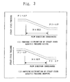
- FIG. 5 shows experimental results that confirmed the effect of the noise reduction method of the present invention. More specifically, the figure shows a measured amount of noise reduction in the case of no jet flow existing under the following condition: the perforated plate is installed in a flow channel through which noise propagates; a jet flow is supplied to the flow channel through the holes of the perforated plate; and the noise frequency and the jet speed are fluctuated.
- the horizontal axis shows the noise frequency
- the vertical axis shows the amount of noise reduction.
- FIG. 5 ( 1 ) shows the experimental result of the case where the jet flow is blown out to a field where acoustic waves propagate.
- FIG. 5 ( 2 ) shows the experimental result of the case where the jet flow is sucked in. It should be noted that the speed of the jet flow shown in the figure has the following relation: Flow speed 1 ⁇ Flow speed 2 ⁇ Flow speed 3 ⁇ Flow speed 4.
- the noise reduction effect is sufficient in the low frequency range of 1 kHz or below. It also shows that the higher the jet speed, the stronger the noise reduction effect. It also shows that the same noise reduction effects can be achieved if a jet is blown out to a fluid through which acoustic waves propagate, or if a fluid through which acoustic waves propagate is sucked from outside.
- the small hole 9 may be provided on part of the solid wall. This allows, from the Bernoulli's theorem referred to earlier, a natural airflow from the blow side to the suction side of the fan 1 through the small hole 9 in accordance with the pressure difference. In this case, the blow side of the fan 1 becomes the suction side of the air that is sucked in through the small hole 9 , and the suction side of the fan 1 becomes the blow side of air that is blown through the small hole 9 . Therefore, as referred to earlier, the noise reduction effect can be achieved on both sides of the fan.
- the small hole 9 can be provided on any wall that divides a position on the blow side of the fan 1 from a position on the suction side of the fan 1 in the duct.
- the same effect can be achieved also in the case where the small holes 9 are provided on an alternative solid wall that divides the blow side from the suction side of the fan 1 , such as the guide 4 , for example, like air conditioning equipment shown in FIG. 6 .
- the noise reduction effect can be achieved with any open area ratio of the small hole (that is defined as the total open area of the small hole for a given area of the duct wall).
- any open area ratio of the small hole that is defined as the total open area of the small hole for a given area of the duct wall.
- the open area ratio of the small hole is high, then the speed of air through the hole must be high. Practically, therefore, a low open area ratio is desirable when considering the feasible pressure difference of actual equipment.
- the open area ratio of the small hole is high, then the amount of bypassing air becomes large which causes a substantial loss. This also shows that a low open area ratio is desirable. Consequently, the most desirable open area ratio of the small hole is as small as 1% or 2%. For practical purposes, however, an open area ratio up to 10% is considered acceptable for the small hole.
- any size can be used for the diameter of the small hole.
- available pressure for the fan is limited. For all of these reasons, therefore, it is desirable to keep the same open area of the small hole for practical purposes.
- the diameter of the small hole is large, however, the number of the small holes must be reduced to keep the same open area ratio of the small hole. Because a vortex occurs at the end of the small hole, and a jet angle formed by a jet blow is constant, if the diameter of the small hole is large, then the effective range of the jet flow gets narrow. This lowers the effect on noise reduction.
- the most desirable size of the diameter of the small hole is as small as 1 mm or 2 mm. For practical purposes, however, a diameter up to 10 mm is considered acceptable for the small hole.
- FIG. 7 is a block diagram of air conditioning equipment illustrating a noise reduction method according to a second embodiment.
- the air conditioning equipment is a ceiling built-in type indoor unit.
- a housing 3 a first air duct, contains a fan 1 and a heat exchanger 2 .
- Inlet air 5 is sucked in through an air inlet and outlet air 6 is blown out through an air outlet.
- a connection duct 11 a second air duct, is installed outside the housing 3 .
- the connection duct 11 has small holes 9 on the suction side and the blow side of the fan 1 .
- the inlet air 5 sucked in through the air inlet into the housing 3 by the induction effect of the fan 1 is supplied to the heat exchanger 2 .
- the air is then heated in a heating operation and cooled in a cooling operation in the heat exchanger 2 , and then blown out from the housing into a room as the outlet air 6 .
- the air conditioning equipment shown in FIG. 7 is different from that shown in FIG. 1 of the first embodiment in that a position on the blow side and a position on the suction side of the fan 1 do not stand side by side over a solid wall. Instead, as shown in FIG. 7 , porous plates with the small holes 9 are installed anywhere on the blow side wall and the suction side wall of the fan 1 and connected by means of the connection duct 11 .
- the small holes 9 and the connection duct 11 can be provided anywhere on the blow duct side and the suction duct side of the fan 1 . Accordingly, they may be installed outside the existing housing 3 as shown in FIG. 7 , or otherwise installed inside the existing housing 3 as shown in FIG. 8 and FIG. 9 . In these cases, because the small holes 9 and the connection duct 11 are close to the fan, the pressure difference is large, and therefore the noise reduction effect is high (highest with a FIG. 9 configuration). In addition, the small holes 9 and the connection duct 11 may be built in the housing 3 , which allows for an easy and low-cost manufacturing.
- the housing 3 contains not only a fan but also a compressor for compressing a refrigerant, and therefore causes noise.
- the noise reduction method of the present invention however, the same noise reduction is allowed equally with the acoustic waves of the same frequency, regardless of the sound types of sound sources. This is clear from the noise reduction mechanism discussed in the first embodiment.
- the noise reduction effect can be achieved with any open area ratio of the small hole (that is defined as the total open area of the small hole for a given area of the duct wall).
- any open area ratio of the small hole that is defined as the total open area of the small hole for a given area of the duct wall.
- the open area ratio of the small hole is high, then the speed of air through the hole must be high. Practically, therefore, a low open area ratio is desirable when considering the feasible pressure difference of actual equipment.
- the open area ratio of the small hole is high, then the amount of bypassing air becomes large which causes a substantial loss. This also shows that a low open area ratio is desirable. Consequently, the most desirable open area ratio of the small hole is as small as 1% or 2%. For practical purposes, however, an open area ratio up to 10% is considered acceptable for the small hole.
- any size can be used for the diameter of the small hole.
- available pressure for the fan is limited. For all of these reasons, therefore, it is desirable to keep the same open area of the small hole for practical purposes.
- the diameter of the small hole is large, however, the number of the small holes must be reduced to keep the same open area ratio of the small hole. Because a vortex occurs at the end of the small hole, and a jet angle formed by a jet blow is constant, if the diameter of the small hole is large, then the effective range of the jet flow gets narrow. This lowers the effect on noise reduction.
- the most desirable size of the diameter of the small hole is as small as 1 mm or 2 mm. For practical purposes, however, a diameter up to 10 mm is considered acceptable for the small hole.
- the small holes 9 are provided on both ends of the connection duct 11 .
- the small holes 9 may be provided only on either end thereof instead.
- the small holes 9 are provided at both ends of the connection duct 11 .
- the small holes 9 may be provided at either end in a large number and big diameter holes at the other end in a small number.
- FIG. 11 is a block diagram of air conditioning equipment illustrating a noise reduction method according to a third embodiment.
- inlet air 5 that is sucked in through an air inlet into a housing 3 by the induction effect of a fan 1 is heated and cooled through a heat exchanger 2 , and then blown out from the housing 3 as outlet air 6 .
- a perforated duct including a large number of small holes is installed at an air outlet.
- a connection duct that is in contact with a top panel of the housing 3 is provided.
- the top panel of the housing 3 includes a small number of big diameter holes, which link to the suction side of the fan.
- the outlet air 6 follows a pressure difference that is created by the fan and flows from the blow side towards the suction side of the fan through the connection duct 11 .
- This allows reducing noise on the air outlet side with the small holes 9 .
- Such effective noise reduction cannot be expected on the side with the big diameter holes 12 .
- a lower cost configuration may be achieved compared to the case where the small holes are provided on both sides.
- the perforated duct including small a large number of holes is installed at the air outlet.
- a plurality of small perforated duds may be installed on the air outlet side.
- FIG. 12 is a block diagram of air conditioning equipment illustrating a noise reduction method according to a fourth embodiment.
- a plurality of small perforated ducts 13 is installed on the air outlet side.
- the larger is a value obtained by dividing the length of the inner periphery of a fan duct by the sectional area of the duct, the higher is the noise reduction effect. Therefore, the air conditioning equipment thus configured allows for much higher noise reduction than the case of the second embodiment.
- the smaller is the inside diameter of the duct the higher is the frequency range that receives the noise reduction effect. Accordingly, higher overall noise reduction effects can be achieved.
- the amount of air that is bypassed to the air inlet side is also increased, and therefore the diameter of a duct needs to be determined according to the system.
- FIG. 13 is a block diagram of fan equipment illustrating a noise reduction method according to a fifth embodiment.
- a fan duct 10 a first air duct, contains a fan blade 1 a .
- Inlet air 5 is sucked in towards the fan blade 1 a , and outlet air 6 is blown out through the fan blade 1 a .
- Small holes 9 are provided on the suction side wall and the blow side wall of the fan blade 1 a in the fan duct 10 , and linked to each other by means of a connection duct 11 as a second air duct.
- the inlet air 5 is sucked in on one side of the fan duct by the induction effect of the fan blade 1 a , and blown outside from the fan duct 10 as the outlet air 6 .
- the fan equipment shown in FIG. 13 differs from the one shown in FIG. 8 of the second embodiment only in that there is no heat exchanger and the air duct is the fun duct, instead of the housing. Therefore, as shown in the figure, if the small holes 9 are provided on the walls before and after the fan blade 1 a and linked to each other by means of the connection duct 11 , then air flows through the connection duct. This will allow for the same noise reduction.
- connection duct 11 may be installed outside the fan duct 10 as shown in FIG. 13 or otherwise installed inside the fan duct 10 as shown in FIG. 14 .
- an existing fan duct can be installed with a partial alteration by some additional work. This is suitable for the case of renewal.
- a fan unit incorporating the small holes 9 and the connection duct 11 can be manufactured. This allows space saving for installation together with a merit of low cost.
- FIG. 13 and FIG. 14 show the fan blade 1 a as if it is a propeller fan, which is not the only possibility.
- a turbo fan shown in FIG. 15 and a sirocco fan shown in FIG. 16 are also possible alternatives. If they allow installing the small holes 9 and the connection duct 11 together, the same effect can be achieved.
- the noise reduction effect can be achieved with any open area ratio of the small hole (that is defined as the total open area of the small hole for a given area of the duct wall).
- any open area ratio of the small hole that is defined as the total open area of the small hole for a given area of the duct wall.
- the open area ratio of the small hole is high, then the speed of air through the hole must be high. Practically, therefore, a low open area ratio is desirable when considering the feasible pressure difference of actual equipment.
- the open area ratio of the small hole is high, then the amount of bypassing air becomes large which causes a substantial loss. This also shows that a low open area ratio is desirable. Consequently, the most desirable open area ratio of the small hole is as small as 1% or 2%. For practical purposes, however, an open area ratio up to 10% is considered acceptable for the small hole.
- any size can be used for the diameter of the small hole.
- available pressure for the fan is limited. For all of these reasons, therefore, it is desirable to keep the same open area of the small hole for practical purposes.
- the diameter of the small hole is large, however, the number of the small holes must be reduced to keep the same open area ratio of the small hole. Because a vortex occurs at the end of the small hole, and a jet angle formed by a jet blow is constant, if the diameter of the small hole is large, then the effective range of the jet flow gets narrow. This lowers the effect on noise reduction.
- the most desirable size of the diameter of the small hole is as small as 1 mm or 2 mm. For practical purposes, however, a diameter up to 10 mm is considered acceptable for the small hole.
- the small holes 9 are provided on the both ends of the connection duct 11 .
- the small holes 9 may be provided on one end in a large number and big diameter holes may be provided on the other end in a small number.
- the pressure difference of the fan allows air to flow through the duct 11 , so that noise can be reduced on the side with the small holes 9 .
- Such an effective noise reduction cannot be expected on the side with the big diameter holes.
- noise intrusion to the room side is sufficiently banned, so that it is satisfactory effective with duct air conditioning for funning air to a room, for example.
- a lower cost structure may be achieved compared to the case where the small holes are provided on both sides.
- the fan blade 1 a is installed in the fan duct 10 as the first air duct.
- the first air duct cannot always be the solid wall. From the same principle, effective noise reduction may be achieved with any system in which a fluid flows near a solid body and through which noise propagates.
- FIG. 15 also shows one with no apparent air duct. Air blows out through fan blades, and small holes are provided near there. That is all. Thus, it is extreme, but the same effect can be achieved if a fan blade contains small holes on itself and if the fan can make air flow through the small holes.
- FIG. 17 and FIG. 18 are bock diagrams of fan equipment illustrating a noise reduction method according to an eighth embodiment.
- a fan 1 is installed in a fan duct 10 .
- Inlet air 5 is sucked in by the fan 1 .
- Outlet air 6 is blown out from the fan 1 .
- Small holes 9 are provided on the wall of the fan duct 10 .
- FIG. 17 shows that the fan 1 is located on the entrance side of the fan duct 10 and the distance between the fan 1 and the outlet air 6 is substantially long.
- FIG. 18 shows, on the other hand, that the fan 1 is located on the exit side of the fan duct 10 and the distance between the inlet air 5 and the fan 1 is substantially long.
- the distance between the fan 1 and the outlet air 6 is substantially long. Therefore, some pressure difference is secured between air pressure near the air outlet of the fan 1 in the fan duct 10 and air pressure outside the fan duct 10 (no more pressure than the inlet air). Small holes 9 provided on the wall of the fan duct 10 near the air outlet of the fan 1 alone allow air to flow through the small holes 9 from the inside to the outside of the fan duct. This reduces noise towards the blow side of the fan 1 .
- the noise reduction mechanism refer to the first embodiment.
- the distance between the inlet air 5 and the fan 1 is substantially long. Therefore, some pressure difference is secured between air pressure near the air inlet of the fan 1 in the fan duct 10 and air pressure outside the fan duct 10 (no more pressure than the outlet air). Small holes 9 provided on the wall of the fan duct 10 near the air outlet of the fan 1 alone allow air to flow through the small holes from the outside to the inside of the fan duct. This reduces noise towards the suction side of the fan 1 .
- the noise reduction mechanism refer to the first embodiment.
- the duct is so long that some pressure difference occurs between the inside and the outside of the duct, which allows airflow through the small holes.
- the duct of no more than 5 cm long, for example, can be substantially long if a pressure difference occurs.
- the noise reduction effect can be achieved with any open area ratio of the small hole (that is defined as the total open area of the small hole for a given area of the duct wall).
- any open area ratio of the small hole that is defined as the total open area of the small hole for a given area of the duct wall.
- the open area ratio of the small hole is high, then the speed of air through the hole must be high. Practically, therefore, a low open area ratio is desirable when considering the feasible pressure difference of actual equipment.
- the open area ratio of the small hole is high, then the amount of bypassing air becomes large which causes a substantial loss. This also shows that a low open area ratio is desirable. Consequently, the most desirable open area ratio of the small hole is as small as 1% or 2%. For practical purposes, however, an open area ratio up to 10% is considered acceptable for the small hole.
- any shape can be used for the diameter of the small hole.
- available pressure for the fan is limited. For all of these reasons, therefore, it is desirable to keep the same open area of the small hole for practical purposes.
- the diameter of the small hole is large, however, the number of the small holes must be reduced to keep the same open area ratio of the small hole. Because a vortex occurs at the end of the small hole, and a jet angle formed by a jet blow is constant, if the diameter of the small hole is large, then the effective range of the jet flow gets narrow. This lowers the effect on noise reduction.
- the most desirable size of the diameter of the small hole is as small as 1 mm or 2 mm. For practical purposes, however, a diameter up to 10 mm is considered acceptable for the small hole.
- FIG. 19 is a block diagram of fan equipment illustrating a noise reduction method according to a ninth embodiment.
- a fan duct 10 contains a fan 1 and a flow-channel separator 14 .
- the flow-channel separator 14 is in contact with the fan duct 10 on the upstream side. On the downstream side, it forms into a nozzle so that air blows from the fan 1 through the flow channel narrowed a little. Additionally, the flow-channel separator 14 contains small holes 9 in large number on the duct wall before the nozzle portion.
- any shape such as circle or rectangle may be employed.
- the shape may be the same as or different from that of the fan duct 10 .
- inlet air 5 is sucked in from one side of the fan duct by the inducing effect of the fan 1 , and increased in pressure by the fan. Thereafter, at the nozzle portion of the flow-channel separator 14 , the air is reduced in pressure and then blown out. This results in causing a pressure difference between before and after the nozzle portion of the flow-channel separator 14 . This causes a pressure difference between both ends of the small holes 9 provided on the duct wall of the flow-channel separator 14 before the nozzle portion. This allows air to flow through the small holes 9 . The air then meets air that has been blown out from the nozzle, and is blown outside the fan duct 10 as outlet air 6 . Therefore, from the same principle as that discussed in the first embodiment, noise propagated from the inflow side of the flow-channel separator 14 (including the generated sound of the fan 1 ) is reduced where the small holes 9 are provided.
- the flow-channel separator 14 and the small holes 9 may be provided on the suction side of the fan 1 . This allows reducing noise propagated to the suction side of the fan. Otherwise, FIG. 19 and FIG. 20 may be incorporated, so that the flow-channel separator 14 and the small holes 9 are provided on the suction side and the exit side of the fan. This allows reducing noise propagated to the suction side and the blow side of the fan.
- the noise reduction effect can be achieved with any open area ratio of the small hole (that is defined as the total open area of the small hole for a given area of the duct wall).
- any open area ratio of the small hole that is defined as the total open area of the small hole for a given area of the duct wall.
- the open area ratio of the small hole is high, then the speed of air through the hole must be high.
- the most desirable open area ratio of the small hole is as small as 1% or 2%.
- an open area ratio up to 10% is considered acceptable for the small hole.
- any size can be used for the diameter of the small hole.
- available pressure for the fan is limited. For all of these reasons, therefore, it is desirable to keep the same open area of the small hole for practical purposes.
- the diameter of the small hole is large, however, the number of the small holes must be reduced to keep the same open area ratio of the small hole. Because a vortex occurs at the end of the small hole, and a jet angle formed by a jet blow is constant, if the diameter of the small hole is large, then the effective range of the jet flow gets narrow. This lowers the effect on noise reduction.
- the most desirable size of the diameter of the small hole is as small as 1 mm or 2 mm. For practical purposes, however, a diameter up to 10 mm is considered acceptable for the small hole.
- FIG. 21 is a block diagram of fan equipment illustrating a noise reduction method according to a tenth embodiment.
- a fan duct 10 contains a fan 1 and a flow-channel separator 14 .
- the passage flow-channel separator 14 is formed to narrow the flow channel.
- the flow-channel separator 14 is open on the upstream side and in contact with the fan duct 10 on the downstream side. Then, the flow-channel separator 14 contains a large number of small holes 9 on the wall surrounding the flow channel narrowed.
- inlet air 5 is sucked in from one side of the fan duct by the inducing effect of the fan 1 , and increased in pressure by the fan. Thereafter, the air passes through the narrowed flow channel of the flow-channel separator 14 . This accelerates the flow speed.
- Dynamic pressure is proportional to squared fluid speed. Therefore, in the narrowed flow channel, dynamic pressure occurs depending on the fluid speed. Outside the narrowed flow channel, however, there is no airflow and therefore no dynamic pressure occurs. Accordingly, static pressure outside the narrowed flow channel is higher than that in the narrowed flow channel.
- the flow-channel separator 14 and the small holes 9 may be provided on the suction side of the fan 1 . This allows reducing noise propagated to the suction side of the fan.
- FIG. 21 and FIG. 22 may be incorporated, so that the flow-channel separator 14 and the small holes 9 are provided on the suction side and the exit side of the fan. This allows reducing noise propagated to the suction side and the blow side of the fan.
- the noise reduction effect can be achieved with any open area ratio of the small hole (that is defined as the total open area of the small hole for a given area of the duct wall).
- any open area ratio of the small hole that is defined as the total open area of the small hole for a given area of the duct wall.
- the open area ratio of the small hole is high, then the speed of air through the hole must be high.
- the most desirable open area ratio of the small hole is as small as 1% or 2%.
- an open area ratio up to 10% is considered acceptable for the small hole.
- any size can be used for the diameter of the small hole.
- available pressure for the fan is limited. For all of these reasons, therefore, it is desirable to keep the same open area of the small hole for practical purposes.
- the diameter of the small hole is large, however, the number of the small holes must be reduced to keep the same open area ratio of the small hole. Because a vortex occurs at the end of the small hole, and a jet angle formed by a jet blow is constant, if the diameter of the small hole is large, then the effective range of the jet flow gets narrow. This lowers the effect on noise reduction.
- the most desirable size of the diameter of the small hole is as small as 1 mm or 2 mm. For practical purposes, however, a diameter up to 10 mm is considered acceptable for the small hole.
- the flow-channel separator 14 is formed into a bell mouth shape on the upstream side.
- the bell mouth shape is desirable without unwanted pressure damage or hitting sound.
- any shape can be used for the flow-channel separator 14 on the upstream side.
- a pointed shape is one possibility.
- a pipe whose diameter is the same as that of the section where the small holes 9 are provided is another possibility.
- any shape can be used for the flow-channel separator 14 on the downstream side.
- a bell mouth or a diffuser is used on the downstream side as well. In this case, pressure recovers on the downstream side of the flow channel. This allows reducing overall pressure damage.
- FIG. 23 is a block diagram of refrigeration cycle equipment illustrating a pressure pulsation reduction method according to an eleventh embodiment.
- high-temperature high-pressure gas refrigerant after compressed by a compressor 20 turns to liquid refrigerant when condensed in a condenser 21 .
- the liquid refrigerant is reduced in pressure in regulator means 23 , evaporated in an evaporator 24 , and turns to low-temperature low-pressure gas refrigerant.
- the gas refrigerant is sucked in by the compressor 20 .
- the compressor 20 contains an electric drive motor and is configured as follows. Motor rotation influences rotor rotation, along with which the clearance volume of a compression chamber varies. Fluid sucked in by the compression chamber is compressed and acquires specified pressure or specified rotation angle. The fluid is discharged at once thereafter from the compressor. Therefore, the pressure of the fluid discharged from the compressor 20 also contains a pulsation component including a higher harmonic wave component when the fundamental frequency is the rotational frequency of the compressor. Also, needless to mention that the pressure of the compressor on the suction side also contains the pulsation component including the higher harmonic wave component when the fundamental frequency is the rotational frequency of the compressor.
- pressure pulsation means needs to be installed in a flow channel near the compressor 20 so as to reduce pressure pulsation.
- a pressure difference between both ends of a perforated plate forms a contraction flow through the holes according to the pressure difference ( FIG. 24 ).
- shear effect in the surrounding fluid converts part of the energy of the contraction flow into vortex energy, thereby generating a vortex.
- a generated vortex is swept away from the holes by the contraction flow. Then, in the transfer process, it is converted into thermal energy, that is, temperature rise of the surrounding fluid, and pressure energy, that is, pulsation component release to the surrounding fluid when influenced by shearing and friction in the surrounding fluid.
- the vortex dissipates.
- a series of this vortex generation and dissipation are repeated continuously.
- the dimension of a vortex generated by the contraction flow at the holes depends upon a diameter d of the hole.
- a frequency f of pressure pulsation generated by a vortex is expressed as: f ⁇ U/d where U denotes the speed of the contraction flow, so that the generation period of a vortex is 1/f.
- pressure pulsation whose wavelength ⁇ is considerably longer than the diameter of the hole ( ⁇ >>d) enters near the contraction flow.
- pressure pulsation fluctuates periodically to the plus or minus side of the steady state pressure.
- the steady state pressure rises on the upstream side and drops on the downstream side of the holes at the instant of vortex generation as shown in FIG. 25 .
- the pressure pulsation reduction effect based on this principle is premised on that the pressure fluctuation cycle is considerably slower than the speed of vortex generation by the contraction flow. Then, the effect is especially high in the low frequency range.
- FIG. 27 shows experimental results that confirmed the effect of the pressure pulsation reduction method of the present invention. More specifically, the figure shows a measured amount of pressure pulsation reduction in the case of no jet flow existing under the following condition: the perforated plate is installed in a flow channel through which pressure pulsation propagates; a jet flow is supplied to the flow channel through the holes of the perforated plate; and the frequency of the pressure pulsation and the speed of the jet flow are fluctuated.
- the horizontal axis shows the pressure pulsation frequency and the vertical axis shows the amount of pressure pulsation reduction.
- FIG. 27 ( 1 ) shows the experimental result of the case where the jet flow is blown out to a field where acoustic waves propagate.
- FIG. 27 ( 2 ) shows the experimental result of the case where the jet flow is sucked in. It should be noted that the speed of the jet flow shown in the figure has the following relation: Flow speed 1 ⁇ Flow speed 2 ⁇ Flow speed 3 ⁇ Flow speed 4.
- pressure pulsation reduction means 30 to which the aforementioned mechanism is applied is installed.
- the pressure pulsation reduction means 30 contains a flow-channel separator 14 , which is formed to narrow the flow channel.
- the flow-channel separator 14 is open on the upstream side and in contact with the surrounding wall on the downstream side. Then, the flow-channel separator 14 contains a large number of small holes 9 on the wall surrounding the narrowed flow channel.
- a fluid flowing into the pressure pulsation reduction means 30 passes through the narrowed flow channel of the flow-channel separator 14 .
- Dynamic pressure is proportional to squared fluid speed. Therefore, in the narrowed flow channel, dynamic pressure occurs depending on the fluid speed. Outside the narrowed flow channel, however, there is no flow and therefore no dynamic pressure occurs. Accordingly, static pressure outside the narrowed flow channel is higher than that in the narrowed flow channel. Consequently, static pressure at the both ends of the small holes 9 provided around the narrowed flow channel is higher outside than inside. This forms a flow through the small holes 9 . Then, the fluid blown into the narrowed flow channel through the small holes 9 meets a fluid through the narrowed flow channel, and is then discharged from the pressure pulsation reduction means 30 .
- the pressure pulsation reduction effect is obtained. Therefore, the pressure pulsation of the refrigerant flowing into the pressure pulsation reduction means 30 is reduced in pulsation in the section where the small holes 9 are provided. Reduction in the pressure pulsation of refrigerant allows preventing noise caused by pipeline vibrations.
- the pressure pulsation reduction means 30 may alternatively be installed on the suction side of the compressor 20 . In this case, pressure pulsation reduction may be achieved on the suction side of the compressor. Otherwise, as shown in FIG. 29 , the pressure pulsation reduction means 30 may be installed on the suction side and the discharge side of the compressor instead. In this case, pressure pulsation reduction propagating to both the suction side and the discharge side of the compressor may be achieved. Still alternatively, as shown in FIG.
- the pressure pulsation reduction means 30 may be formed such that small holes 9 provided on pipeline walls on the discharge side and the suction side are connected by means of a connection pipe 31 . This forms a flow from the small holes on the discharge side to the small holes on the suction side of the compressor, which allows reducing pressure pulsation on both the discharge side and the suction side.
- the pressure pulsation reduction effect can be achieved with any open area ratio of the small hole (that is defined as the total open area of the small hole for a given area of the duct wall).
- any open area ratio of the small hole that is defined as the total open area of the small hole for a given area of the duct wall.
- any size can be used for the diameter of the small hole.
- the most desirable size of the diameter of the small hole is as small as 1 mm or 2 mm. For practical purposes, however, a diameter up to 10 mm is considered acceptable for the small hole.
- the flow-channel separator 14 is formed into a diffuser on the upstream side.
- a flow through the small holes 9 is the only requirement for noise reduction.
- a pipe whose diameter is the same as that of the section where the small holes 9 are provided is one possibility, for example.
- the configuration may include a plurality of perforated small ducts installed in the flow channel. This allows for higher pressure pulsation reduction.
- any refrigerant can be used for the refrigerant that flows inside the refrigeration cycle equipment, for example, such as single component refrigerants like R22 etc., mixed refrigerants of a three-component system like R407C, mixed refrigerants of a two-component system like R410A, HC refrigerants such as propane etc., and natural refrigerants such as CO 2 etc.
- the pressure pulsation reducer 30 may be applied to pump equipment as shown in FIG. 31 through FIG. 34 .
- the pressure pulsation of a medium such as water or brine that flows through a flow channel can be reduced.
- the operation of this case will not be discussed here in detail, since it is the same as that of the refrigeration cycle equipment.
- Pressure pulsation reduction means may be installed on either the upstream side or the downstream side of a compressing section for compressing a fluid. From the structural point of view, therefore, a compressor 20 may contain the pressure pulsation reduction means.
- FIG. 35 is a diagram illustrating an internal structure of a single screw compressor according to a twelfth embodiment.
- Pressure pulsation reduction means 30 is installed in an oil separator 43 on the downstream side of a compression chamber 42 .
- a flow-channel separator 14 in the pressure pulsation reduction means 30 is in contact with the surrounding wall of the oil separator 43 on the upstream side.
- the flow-channel separator 14 on the downstream side, is formed into a nozzle so as to blow a fluid through a narrowed flow channel. Then, small holes 9 are provided on the duct wall of the flow-channel separator 14 before the nozzle portion.
- Such a configuration allows a fluid flowing into the pressure pulsation reduction means 30 to be reduced in pressure at the nozzle portion of the flow-channel separator 14 and then blown out. This causes a pressure difference between before and after the nozzle portion of the flow-channel separator 14 .
- the flow-channel separator 14 in the pressure pulsation reduction means 30 may alternatively be formed such that it is open on the upstream side, in contact with a cylindrical member that extends from the oil separator 43 and encloses the flow-channel separator 14 , for example, on the downstream side, and includes small holes 9 in a large number.
- the air conditioning equipment includes a heat exchanger exchanging heat between refrigerant of a refrigeration cycle and air, a fan funning air to the heat exchanger, an air duct in which the fan is installed and through which an acoustic wave propagates, and a plurality of small holes blowing a jet to the air duct, and sucking a jet from the air duct according to a pressure difference between a blow side and a suction side of the fan. This allows for sufficient noise reduction in the low frequency region of a few hundred hertz or below.
Abstract
Description
f∝U/d
where U denotes the speed of the contraction flow, so that the generation period of a vortex is 1/f.
where P1 and P2 denote pressures on both sides of the holes. When the steady state density p rises, then the steady state speed U drops. Thus, when the steady state acoustic pressure rises, that is, pressure fluctuation ΔP>0, the steady state speed drops, that is, speed fluctuation ΔU<0.
E=∫(ΔP·ΔU)·dt
Therefore, as referred to earlier, when ΔP>0, then ΔU<0, and when ΔP<0, then ΔU>0. Thus, the mechanical energy E is always negative (
f∝U/d
where U denotes the speed of the contraction flow, so that the generation period of a vortex is 1/f.
where P1 and P2 denote pressures on both sides of the holes. When the steady state density p rises, then the steady state speed U drops. Thus, when the steady state pressure rises, that is, pressure fluctuation ΔP>0, the steady state speed drops, that is, speed fluctuation ΔU<0.
E=∫(ΔP·ΔU)·dt
Therefore, as referred to earlier, when ΔP>0, then ΔU<0, and when ΔP<0, then ΔU>0. Thus, the mechanical energy E is always negative (
Claims (5)
Applications Claiming Priority (3)
| Application Number | Priority Date | Filing Date | Title |
|---|---|---|---|
| JP2002-289663 | 2002-02-10 | ||
| JP2002289663 | 2002-10-02 | ||
| PCT/JP2003/010741 WO2004031660A1 (en) | 2002-10-02 | 2003-08-26 | Method for reducing noise of air conditioner, fan unit and apparatus, pressure pulsation reducer of refrigeration cycle unit, pressure pulsation reducer of pump unit and pressure pulsation reducing method of apparatus |
Publications (2)
| Publication Number | Publication Date |
|---|---|
| US20070060038A1 US20070060038A1 (en) | 2007-03-15 |
| US7856837B2 true US7856837B2 (en) | 2010-12-28 |
Family
ID=32063749
Family Applications (1)
| Application Number | Title | Priority Date | Filing Date |
|---|---|---|---|
| US10/529,870 Active 2025-06-27 US7856837B2 (en) | 2002-02-10 | 2003-08-26 | Air conditioning equipment, fan equipment, method of reducing noise of equipment, pressure pulsation reducer for refrigeration cycle equipment, pressure pulsation reducer for pump equipment and method of reducing pressure pulsation of equipment |
Country Status (6)
| Country | Link |
|---|---|
| US (1) | US7856837B2 (en) |
| EP (2) | EP2154451B1 (en) |
| JP (1) | JP4325867B2 (en) |
| ES (2) | ES2732068T3 (en) |
| HK (1) | HK1141074A1 (en) |
| WO (1) | WO2004031660A1 (en) |
Cited By (4)
| Publication number | Priority date | Publication date | Assignee | Title |
|---|---|---|---|---|
| US20080242210A1 (en) * | 2005-09-29 | 2008-10-02 | Airbus Deutschland Gmbh | Low-Noise Volume Flow Rate Throttling of Fluid-Carrying Pipes |
| US9835176B2 (en) | 2013-04-05 | 2017-12-05 | Acoustiflo Llc | Fan inlet air handling apparatus and methods |
| US10087954B2 (en) | 2013-02-08 | 2018-10-02 | Trane International Inc. | HVAC system with noise reducing tube |
| US11536501B2 (en) | 2018-09-14 | 2022-12-27 | Carrier Corporation | Oil separator with integrated muffler |
Families Citing this family (19)
| Publication number | Priority date | Publication date | Assignee | Title |
|---|---|---|---|---|
| EP1888982B1 (en) * | 2005-05-31 | 2010-12-15 | Carrier Corporation | Methods and apparatus for reducing the noise level outputted by oil separator |
| JP4301227B2 (en) * | 2005-09-15 | 2009-07-22 | セイコーエプソン株式会社 | Electro-optical device and manufacturing method thereof, electronic apparatus, and condenser |
| DE102006050339A1 (en) * | 2006-10-25 | 2008-04-30 | Valeo Klimasysteme Gmbh | Ventilation system with sound barrier |
| JP4610626B2 (en) * | 2008-02-20 | 2011-01-12 | 三菱電機株式会社 | Heat exchanger and ceiling-embedded air conditioner installed in ceiling-embedded air conditioner |
| US11828678B2 (en) * | 2010-03-15 | 2023-11-28 | Klatu Networks, Inc. | Managing the effectiveness of repairs in refrigeration assets |
| US10456686B2 (en) | 2012-09-05 | 2019-10-29 | Zynga Inc. | Methods and systems for adaptive tuning of game events |
| JP6139189B2 (en) * | 2013-03-13 | 2017-05-31 | 東プレ株式会社 | Blower unit |
| US9675889B2 (en) | 2014-09-10 | 2017-06-13 | Zynga Inc. | Systems and methods for determining game level attributes based on player skill level prior to game play in the level |
| US10561944B2 (en) | 2014-09-10 | 2020-02-18 | Zynga Inc. | Adjusting object adaptive modification or game level difficulty and physical gestures through level definition files |
| EP3211331A1 (en) * | 2016-02-25 | 2017-08-30 | Halton OY | Apparatus for conditioning a space |
| CN107166538A (en) * | 2017-06-22 | 2017-09-15 | 珠海格力电器股份有限公司 | Air conditioner |
| DE202017006578U1 (en) * | 2017-12-22 | 2019-03-25 | Thomas Roggenkamp | climate chamber |
| CN111256281B (en) * | 2018-11-30 | 2021-10-22 | 广东美的制冷设备有限公司 | Operation control method and system, compressor and air conditioner |
| TWI710706B (en) * | 2019-05-24 | 2020-11-21 | 宏碁股份有限公司 | Centrifugal heat dissipation fan |
| DE102020207407A1 (en) * | 2020-06-16 | 2021-12-16 | BSH Hausgeräte GmbH | Refrigeration device and compressor therefor |
| TWI790737B (en) * | 2021-09-06 | 2023-01-21 | 宏碁股份有限公司 | Electronic system with heat dissipation and feedforward active noise control function |
| CN114001420B (en) * | 2021-10-27 | 2023-07-04 | 上海民航新时代机场设计研究院有限公司 | New fan of low noise total heat net effect |
| CN114608789B (en) * | 2022-04-07 | 2023-03-21 | 中国空气动力研究与发展中心低速空气动力研究所 | Test method for studying jet flow noise and sound transmission |
| JP2024052573A (en) * | 2022-09-30 | 2024-04-11 | ダイキン工業株式会社 | Air conditioners and air purifiers |
Citations (22)
| Publication number | Priority date | Publication date | Assignee | Title |
|---|---|---|---|---|
| US2875787A (en) * | 1956-03-27 | 1959-03-03 | Westinghouse Air Brake Co | Pulsation dampener device |
| US3070977A (en) | 1961-03-31 | 1963-01-01 | Heat X Inc | Refrigeration system, including oil separator and muffler unit and oil return arrangement |
| JPS57173686A (en) | 1981-04-20 | 1982-10-26 | Hitachi Plant Eng & Constr Co | Muffler for blowing duct |
| US4381651A (en) | 1980-07-17 | 1983-05-03 | Nippondenso Co., Ltd. | Silencer in a refrigeration system |
| JPS58194908A (en) | 1982-03-18 | 1983-11-14 | ブリティシュ・テレコミュニケーションズ・パブリック・リミテッド・カンパニ | Dielectric and/or pyroelectric film and tube, manufacture and device |
| JPS5921951A (en) | 1982-07-23 | 1984-02-04 | 三洋電機株式会社 | Heat pump system separation type air conditioner |
| JPS613943A (en) | 1984-06-18 | 1986-01-09 | Toupure Kk | Air-conditioning equipment |
| US4652217A (en) * | 1982-08-12 | 1987-03-24 | Diesel Kiki Co., Ltd. | Double acting type compressor |
| JPH04369342A (en) | 1991-06-17 | 1992-12-22 | Hitachi Ltd | Noise eliminator for air-conditioner |
| JPH07247905A (en) | 1994-03-11 | 1995-09-26 | Ishikawajima Harima Heavy Ind Co Ltd | Liner structure of exhaust nozzle for supersonic aircraft |
| JPH08143A (en) | 1994-06-24 | 1996-01-09 | Goosen:Kk | Tool for rewinding fishing line and line package of fishing line having the same attached thereto |
| JPH0814704A (en) | 1994-06-27 | 1996-01-19 | Aisin Seiki Co Ltd | Piping unit and air conditioner having such piping unit |
| JPH08143149A (en) | 1994-11-26 | 1996-06-04 | Yoshitaka Aoyama | Muffling device for part feed line |
| JPH09112488A (en) | 1995-10-17 | 1997-05-02 | Mitsubishi Heavy Ind Ltd | Centrifugal fan |
| WO1997021024A1 (en) | 1995-12-04 | 1997-06-12 | Vibron Limited | Reactive acoustic silencer |
| US5638940A (en) | 1994-07-23 | 1997-06-17 | Aoyama; Yoshitaka | Parts send-out control device for vibratory parts feeder |
| JPH11107959A (en) * | 1997-09-30 | 1999-04-20 | Sanyo Electric Co Ltd | Discharge pipe of sealed compressor |
| EP0926452A1 (en) | 1997-06-17 | 1999-06-30 | Daikin Industries, Limited | Air conditioner |
| JP2000292077A (en) | 1999-02-03 | 2000-10-20 | Nippon Soken Inc | Heat exchanger |
| JP2002250535A (en) | 2001-02-23 | 2002-09-06 | Mitsubishi Heavy Ind Ltd | Air conditioning indoor unit, and air conditioner equipped with the air conditioning indoor unit |
| JP2002350003A (en) | 2001-05-22 | 2002-12-04 | Hitachi Ltd | Air conditioner |
| US20030006089A1 (en) | 2001-07-04 | 2003-01-09 | National Aerospace Laboratory Of Japan | Fine jet control-type sound absorption system |
Family Cites Families (2)
| Publication number | Priority date | Publication date | Assignee | Title |
|---|---|---|---|---|
| JPS58195908A (en) | 1982-05-11 | 1983-11-15 | Shinkichi Doi | Adapting method of car speed to speed control of road |
| JPS58194908U (en) * | 1982-06-21 | 1983-12-24 | マツダ株式会社 | car air conditioner |
-
2003
- 2003-08-26 WO PCT/JP2003/010741 patent/WO2004031660A1/en active Application Filing
- 2003-08-26 ES ES03799088T patent/ES2732068T3/en not_active Expired - Lifetime
- 2003-08-26 EP EP09013762.1A patent/EP2154451B1/en not_active Expired - Lifetime
- 2003-08-26 ES ES09013762.1T patent/ES2443492T3/en not_active Expired - Lifetime
- 2003-08-26 JP JP2004541215A patent/JP4325867B2/en not_active Expired - Lifetime
- 2003-08-26 US US10/529,870 patent/US7856837B2/en active Active
- 2003-08-26 EP EP03799088.4A patent/EP1553360B1/en not_active Expired - Lifetime
-
2010
- 2010-08-02 HK HK10107351.6A patent/HK1141074A1/en not_active IP Right Cessation
Patent Citations (25)
| Publication number | Priority date | Publication date | Assignee | Title |
|---|---|---|---|---|
| US2875787A (en) * | 1956-03-27 | 1959-03-03 | Westinghouse Air Brake Co | Pulsation dampener device |
| US3070977A (en) | 1961-03-31 | 1963-01-01 | Heat X Inc | Refrigeration system, including oil separator and muffler unit and oil return arrangement |
| US4381651A (en) | 1980-07-17 | 1983-05-03 | Nippondenso Co., Ltd. | Silencer in a refrigeration system |
| JPS57173686A (en) | 1981-04-20 | 1982-10-26 | Hitachi Plant Eng & Constr Co | Muffler for blowing duct |
| JPS58194908A (en) | 1982-03-18 | 1983-11-14 | ブリティシュ・テレコミュニケーションズ・パブリック・リミテッド・カンパニ | Dielectric and/or pyroelectric film and tube, manufacture and device |
| JPS5921951A (en) | 1982-07-23 | 1984-02-04 | 三洋電機株式会社 | Heat pump system separation type air conditioner |
| US4652217A (en) * | 1982-08-12 | 1987-03-24 | Diesel Kiki Co., Ltd. | Double acting type compressor |
| JPS613943A (en) | 1984-06-18 | 1986-01-09 | Toupure Kk | Air-conditioning equipment |
| JPH04369342A (en) | 1991-06-17 | 1992-12-22 | Hitachi Ltd | Noise eliminator for air-conditioner |
| JPH07247905A (en) | 1994-03-11 | 1995-09-26 | Ishikawajima Harima Heavy Ind Co Ltd | Liner structure of exhaust nozzle for supersonic aircraft |
| JPH08143A (en) | 1994-06-24 | 1996-01-09 | Goosen:Kk | Tool for rewinding fishing line and line package of fishing line having the same attached thereto |
| JPH0814704A (en) | 1994-06-27 | 1996-01-19 | Aisin Seiki Co Ltd | Piping unit and air conditioner having such piping unit |
| US5638940A (en) | 1994-07-23 | 1997-06-17 | Aoyama; Yoshitaka | Parts send-out control device for vibratory parts feeder |
| USRE37120E1 (en) | 1994-07-23 | 2001-04-03 | Yoshitaka Aoyama | Parts send-out control device for vibratory parts feeder |
| JPH08143149A (en) | 1994-11-26 | 1996-06-04 | Yoshitaka Aoyama | Muffling device for part feed line |
| JPH09112488A (en) | 1995-10-17 | 1997-05-02 | Mitsubishi Heavy Ind Ltd | Centrifugal fan |
| WO1997021024A1 (en) | 1995-12-04 | 1997-06-12 | Vibron Limited | Reactive acoustic silencer |
| EP0926452A1 (en) | 1997-06-17 | 1999-06-30 | Daikin Industries, Limited | Air conditioner |
| JPH11107959A (en) * | 1997-09-30 | 1999-04-20 | Sanyo Electric Co Ltd | Discharge pipe of sealed compressor |
| JP2000292077A (en) | 1999-02-03 | 2000-10-20 | Nippon Soken Inc | Heat exchanger |
| JP2002250535A (en) | 2001-02-23 | 2002-09-06 | Mitsubishi Heavy Ind Ltd | Air conditioning indoor unit, and air conditioner equipped with the air conditioning indoor unit |
| JP2002350003A (en) | 2001-05-22 | 2002-12-04 | Hitachi Ltd | Air conditioner |
| US20030006089A1 (en) | 2001-07-04 | 2003-01-09 | National Aerospace Laboratory Of Japan | Fine jet control-type sound absorption system |
| JP2003015656A (en) | 2001-07-04 | 2003-01-17 | National Aerospace Laboratory Of Japan | Fine jet control type sound absorption system |
| US6772856B2 (en) | 2001-07-04 | 2004-08-10 | National Aerospace Laboratory Of Japan | Fine jet control-type sound absorption system |
Non-Patent Citations (7)
| Title |
|---|
| Abstract of JP11-107959 A to Fijiwara et al. * |
| Bechert, D. W. "Sound Absorption Caused by Vorticity Shedding, Demonstrated With a Jet Flow." Journal of Sound and Vibration. vol. 70 (3). pp. 389-405. 1980. |
| English translation to JP 11-107959 A to Fujiwara et al. * |
| Extended European Search Report and Written Opinion dated Jan. 13, 2010. |
| Howe, M. S. "Attenuation of sound in a low Mach number nozzle flow." J. Fluid Mech. vol. 91, Part 2. pp. 209-229. 1979. |
| Japan Patent Office. International Patent Application No. PCT/JP03/10741. Nov. 25, 2003. 2 pages. |
| Supplementary European Search Report Application/Patent No. 03799088.4-2301dated Feb. 12, 2008. |
Cited By (4)
| Publication number | Priority date | Publication date | Assignee | Title |
|---|---|---|---|---|
| US20080242210A1 (en) * | 2005-09-29 | 2008-10-02 | Airbus Deutschland Gmbh | Low-Noise Volume Flow Rate Throttling of Fluid-Carrying Pipes |
| US10087954B2 (en) | 2013-02-08 | 2018-10-02 | Trane International Inc. | HVAC system with noise reducing tube |
| US9835176B2 (en) | 2013-04-05 | 2017-12-05 | Acoustiflo Llc | Fan inlet air handling apparatus and methods |
| US11536501B2 (en) | 2018-09-14 | 2022-12-27 | Carrier Corporation | Oil separator with integrated muffler |
Also Published As
| Publication number | Publication date |
|---|---|
| JP4325867B2 (en) | 2009-09-02 |
| ES2732068T3 (en) | 2019-11-20 |
| EP2154451B1 (en) | 2013-11-06 |
| ES2443492T3 (en) | 2014-02-19 |
| HK1141074A1 (en) | 2010-10-29 |
| WO2004031660A1 (en) | 2004-04-15 |
| JPWO2004031660A1 (en) | 2006-02-02 |
| EP1553360A4 (en) | 2008-03-12 |
| EP1553360B1 (en) | 2019-05-22 |
| US20070060038A1 (en) | 2007-03-15 |
| EP1553360A1 (en) | 2005-07-13 |
| EP2154451A1 (en) | 2010-02-17 |
Similar Documents
| Publication | Publication Date | Title |
|---|---|---|
| US7856837B2 (en) | Air conditioning equipment, fan equipment, method of reducing noise of equipment, pressure pulsation reducer for refrigeration cycle equipment, pressure pulsation reducer for pump equipment and method of reducing pressure pulsation of equipment | |
| WO2005095875A1 (en) | Flow path device, freezing cycle device, pressure pulsation reducing device, and pressure pulsation reducing method | |
| EP2618066B1 (en) | Blower for outdoor unit, outdoor unit, and refrigeration cycle device | |
| KR20070099053A (en) | Compressor discharge muffler | |
| US11073145B2 (en) | Pressure pulsation traps | |
| JP2010229871A (en) | Centrifugal fan and air conditioning apparatus for vehicle | |
| JP4659066B2 (en) | Channel device | |
| JP2008138661A (en) | Centrifugal blower | |
| EP3702697A1 (en) | Refrigeration cycle device unit, and refrigeration cycle device and electrical equipment | |
| JP7014584B2 (en) | A sound absorbing element for the refrigeration cycle system, a decompression unit with it, and a refrigeration cycle system. | |
| JP5521648B2 (en) | Blower with silencer box | |
| JPWO2019116810A1 (en) | Blower and air conditioner equipped with the same | |
| US20180051698A1 (en) | Compressor noise reduction | |
| JP2003074499A (en) | Blower and air conditioner using it | |
| JP7301236B2 (en) | SCROLL CASING FOR CENTRIFUGAL BLOWER, CENTRIFUGAL BLOWER INCLUDING THIS SCROLL CASING, AIR CONDITIONER AND REFRIGERATION CYCLE DEVICE | |
| JP6681980B2 (en) | Refrigeration cycle device and electric equipment equipped with this refrigeration cycle device | |
| KR100696420B1 (en) | Outdoor unit of Air conditioner | |
| JP2022126944A (en) | turbo blower | |
| WO2020044482A1 (en) | Outdoor unit and refrigeration cycle device | |
| CN114183381A (en) | Volute device, compressor and refrigeration equipment | |
| KR20010008001A (en) | A noise dissipation apparatus for centrifugal refrigerant compressor |
Legal Events
| Date | Code | Title | Description |
|---|---|---|---|
| AS | Assignment |
Owner name: MITSUBISHI DENKI KABUSHIKI KAISHA, JAPAN Free format text: ASSIGNMENT OF ASSIGNORS INTEREST;ASSIGNORS:YAMASHITA, KOUJI;UCHIDA, TSUYOSHI;ISHII, TATSUYA;AND OTHERS;REEL/FRAME:017183/0876;SIGNING DATES FROM 20050425 TO 20050606 Owner name: JAPAN AEROSPACE EXPLORATION AGENCY, JAPAN Free format text: ASSIGNMENT OF ASSIGNORS INTEREST;ASSIGNORS:YAMASHITA, KOUJI;UCHIDA, TSUYOSHI;ISHII, TATSUYA;AND OTHERS;REEL/FRAME:017183/0876;SIGNING DATES FROM 20050425 TO 20050606 Owner name: MITSUBISHI DENKI KABUSHIKI KAISHA, JAPAN Free format text: ASSIGNMENT OF ASSIGNORS INTEREST;ASSIGNORS:YAMASHITA, KOUJI;UCHIDA, TSUYOSHI;ISHII, TATSUYA;AND OTHERS;SIGNING DATES FROM 20050425 TO 20050606;REEL/FRAME:017183/0876 Owner name: JAPAN AEROSPACE EXPLORATION AGENCY, JAPAN Free format text: ASSIGNMENT OF ASSIGNORS INTEREST;ASSIGNORS:YAMASHITA, KOUJI;UCHIDA, TSUYOSHI;ISHII, TATSUYA;AND OTHERS;SIGNING DATES FROM 20050425 TO 20050606;REEL/FRAME:017183/0876 |
|
| STCF | Information on status: patent grant |
Free format text: PATENTED CASE |
|
| FEPP | Fee payment procedure |
Free format text: PAYOR NUMBER ASSIGNED (ORIGINAL EVENT CODE: ASPN); ENTITY STATUS OF PATENT OWNER: LARGE ENTITY |
|
| FPAY | Fee payment |
Year of fee payment: 4 |
|
| MAFP | Maintenance fee payment |
Free format text: PAYMENT OF MAINTENANCE FEE, 8TH YEAR, LARGE ENTITY (ORIGINAL EVENT CODE: M1552) Year of fee payment: 8 |
|
| MAFP | Maintenance fee payment |
Free format text: PAYMENT OF MAINTENANCE FEE, 12TH YEAR, LARGE ENTITY (ORIGINAL EVENT CODE: M1553); ENTITY STATUS OF PATENT OWNER: LARGE ENTITY Year of fee payment: 12 |