US7863797B2 - Electrical devices using electromagnetic rotors - Google Patents
Electrical devices using electromagnetic rotors Download PDFInfo
- Publication number
- US7863797B2 US7863797B2 US12/847,991 US84799110A US7863797B2 US 7863797 B2 US7863797 B2 US 7863797B2 US 84799110 A US84799110 A US 84799110A US 7863797 B2 US7863797 B2 US 7863797B2
- Authority
- US
- United States
- Prior art keywords
- rotor
- stator
- flux
- extensions
- coil
- Prior art date
- Legal status (The legal status is an assumption and is not a legal conclusion. Google has not performed a legal analysis and makes no representation as to the accuracy of the status listed.)
- Expired - Fee Related
Links
Images


Classifications
-
- H—ELECTRICITY
- H02—GENERATION; CONVERSION OR DISTRIBUTION OF ELECTRIC POWER
- H02K—DYNAMO-ELECTRIC MACHINES
- H02K21/00—Synchronous motors having permanent magnets; Synchronous generators having permanent magnets
- H02K21/12—Synchronous motors having permanent magnets; Synchronous generators having permanent magnets with stationary armatures and rotating magnets
-
- H—ELECTRICITY
- H02—GENERATION; CONVERSION OR DISTRIBUTION OF ELECTRIC POWER
- H02K—DYNAMO-ELECTRIC MACHINES
- H02K19/00—Synchronous motors or generators
- H02K19/16—Synchronous generators
- H02K19/22—Synchronous generators having windings each turn of which co-operates alternately with poles of opposite polarity, e.g. heteropolar generators
-
- H—ELECTRICITY
- H02—GENERATION; CONVERSION OR DISTRIBUTION OF ELECTRIC POWER
- H02K—DYNAMO-ELECTRIC MACHINES
- H02K2201/00—Specific aspects not provided for in the other groups of this subclass relating to the magnetic circuits
- H02K2201/12—Transversal flux machines
Definitions
- aspects of the present invention relate to the field of alternator or other electrical output generating devices and to electric motors and other electrically driven devices, and in particular to electrical output generating devices and electrically driven devices, and methods of making and use thereof, that, among other things, improve efficiency of operation, provide higher torque density, and reduce costs and complexity of manufacture, while allowing greater flexibility in operation over related art devices.
- an electrical machine comprises a rotor assembly comprising a first set and a second set of rotor extensions, and a stator assembly comprising a first set and a second set of stator extensions.
- Rotating the rotor assembly about an axis alternates the rotor assembly between a first position and a second position.
- each of the first set of rotor extensions transfers flux to one of the first set of stator extensions
- each of the second set of rotor extensions transfers flux to one of the second set of stator extensions.
- each of the first set of rotor extensions transfers flux to one of the second set of stator extensions
- each of the second set of rotor extensions transfers flux to one of the first set of stator extensions.
- the electrical machine is at least one of a transverse flux machine or a commutated flux machine.
- a method of generating a current in an electrical machine comprises rotating a rotor assembly about an axis to alternate the rotor assembly between a first position and a second position with respect to a stator assembly.
- the rotor assembly comprises a first set and a second set of rotor extensions
- the stator assembly comprises a first set and a second set of stator extensions.
- each of the first set of rotor extensions transfers flux to one of the first set of stator extensions
- each of the second set of rotor extensions transfers flux to one of the second set of stator extensions.
- each of the first set of rotor extensions transfers flux to one of the second set of stator extensions, and each of the second set of rotor extensions transfers flux to one of the first set of stator extensions.
- the electrical machine is at least one of a transverse flux machine or a commutated flux machine.
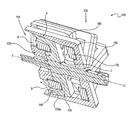
- FIG. 1 shows the internal components for a first exemplary electrical output device or electrically driven device in a partially disassembled view, in accordance with aspects of the present invention
- FIG. 2 is partial cross-sectional assembled view of the exemplary device of FIG. 1 ;
- FIG. 3A is a representative view of an exemplary laminated construction flux conducting material component, usable in accordance with aspects of the present invention.
- FIG. 3B is a cross-sectional view of an assembled exemplary electrical output device or electrically driven device having the internal components shown in FIGS. 1-2 and additional external and other components, in accordance with aspects of the present invention
- FIGS. 4A , 4 B and 4 C present representative views of a tape-like wound toroidal flux conducting component, in accordance with and for use in accordance with aspects of the present invention
- FIG. 5 shows the internal components of a second exemplary electrical output device or electrically driven device in an assembled view, in accordance with aspects of the present invention
- FIG. 6 is a partial cutaway view of the exemplary electrical output device or electrically driven device of FIG. 5 ;
- FIG. 7 is a partial cutaway view of the exemplary electrical output device or electrically driven device of FIG. 5 , rotated relative to the view of FIG. 6 ;
- FIG. 8 is a cross-sectional view of an assembled exemplary electrical output device or electrically driven device having the internal components shown in FIGS. 5-7 and external and other components, in accordance with aspects of the present invention
- FIGS. 9A and 9B illustrate views of an exemplary flux concentrating multiple pole rotor electrical output device or electrically driven device, in accordance with aspects of the present invention
- FIG. 9C presents a representative view of an exemplary alternating magnet and flux concentrator portion of an electrical output device or electrically driven device, in the process of assembly in accordance with aspects of the present invention
- FIG. 9D shows a representative view of the electrical output device or electrically driven device of FIGS. 9A-9B from a view perpendicular to the direction E-E′ shown in FIG. 9B ;
- FIG. 9E is a partial cutaway view of the electrical output device or electrically driven device of FIG. 9B ;
- FIG. 9F shows a representative view of the electrical output device or electrically driven device of FIG. 9D at a slightly rotated rotor position relative to the position of FIG. 9D ;
- FIG. 9G is a partial cutaway view of the electrical output device or electrically driven device of FIG. 9B , after rotation of the rotor as shown in FIG. 9F ;
- FIG. 10 presents another variation of a flux concentrating rotor similar to the variation shown in FIGS. 9A-9G ;
- FIG. 11 shows a representative view of the electrical output device or electrically driven device of FIG. 10 from a view perpendicular to the direction Y-Y′ shown in FIG. 10 .
- FIGS. 1-3B present a first exemplary variation of components of an electrical output device or electrically driven device and a method of operation thereof, in accordance with aspects of the present invention.
- FIG. 1 shows the internal components 100 for a first exemplary single phase alternator (or, for example, a generator or other electrical output device; herein referred to throughout, interchangeably and collectively, as a “device,” “alternator,” or “electric motor”) in a partially disassembled view, in accordance with aspects of the present invention.
- a device or, for example, a generator or other electrical output device; herein referred to throughout, interchangeably and collectively, as a “device,” “alternator,” or “electric motor”
- Such a device is usable in many driven rotation applications to produce electrical output, such as for use with an automobile engine.
- a first, rotating portion 101 of the internal components 100 is similar in design and operation to a conventional Lundell rotor or Claw Pole rotor, used, for example, in many typical related art automobile alternators.
- the rotating portion 101 includes first magnetic polar portions (e.g., north magnetic poles) 120 and a second magnetic polar portions (e.g., south magnetic poles) 130 .
- the first and second magnetic polar portions 120 , 130 encompass an internal coil portion 140 , such as a coiled wire.
- the internal coil portion 140 receives an energizing current (e.g., a fixed current, such as a direct current or DC).
- energizing current e.g., a fixed current, such as a direct current or DC.
- Each of the first and second magnetic polar portions 120 , 130 includes a plurality of poles 120 a , 130 a , respectively, such that a multiple pole rotor (e.g., 18 alternating polarity poles 120 a , 130 a ) is created by the combination of the first and second magnetic polar portions 120 , 130 .
- a multiple pole rotor e.g., 18 alternating polarity poles 120 a , 130 a
- this approach produces an alternating flux when moving past a flux conducting material completing a flux path, analogous to how poles on moving magnets are able to produce an alternating flux in coils when the magnets are moved proximate to such coils in a suitable orientation and direction (e.g., when the magnets move rotationally next to one or more coils having axes perpendicular and circumferential to the axis of the rotating magnets, as is common with some conventional generators or alternators).
- the approach shown in FIG. 1 may simplify manufacturing over a multiple wound approach, since many small diameter coils are not required.
- a second, stationary portion 102 of the internal components of the device 100 includes a first laminated steel or other flux conducting material portion 150 and an output coil 170 .
- first laminated steel or other flux conducting material portion 150 and an output coil 170 .
- each first flux conducting portion 150 aligns with a second magnetic polar portion 130 .
- the first flux conducting portion 150 partially wraps around a first portion of the output coil 170 to form a portion of flux path A, having flux, for example, in the direction of the arrowheads, that continues from the aligned second magnetic polar portion 130 .
- Flux path A is such that the magnetic flux is directed through junction J between the first flux conduction portion 150 and a second flux conducting portion 160 , as shown in FIG. 2 .
- the second flux conducting portion 160 continues the flux path A through the center of the output coil 170 and about the nested rotating portion 101 . In the position of the rotating portion 101 shown in FIG.
- the flux path A then continues from the second flux conducting portion 160 , which is aligned with the first magnetic polar portion 120 , into the first magnetic polar portion 120 , about the internal coil portion 140 and into the second magnetic polar portion 130 , such that a completed flux path A is formed.
- the side by side (“SBS”)-shaped configuration (as opposed to the typical “nested” configuration of a typical related art automotive alternator, for example) shown in FIG. 1 (and also FIG. 2 ) presents one approach to enhancing three dimensional flux paths by locating laminated flux conducting material portions proximate to the magnetic polar portions 120 , 130 in an “end-to-end” configuration.
- the flux conducting portions 150 , 160 may comprise laminated steel, such that abutted flat steel laminate portions make up each flux conducting portion 150 , 160 , with the direction of the flat steel laminate portions laminated lengthwise in the direction of the flow path A.
- FIG. 3A shows an exemplary representative view of the flux conducting material portion 150 , comprising laminated steel portions, in accordance with aspects of the present invention.
- the approach of using laminations allows an essentially two dimensional flux conducting material (each laminate portion) to produce a three dimensional flow of flux (e.g., in path A shown in FIG. 2 ).
- this approach may minimize eddy current and/or other flux related loss with respect to flux travel in direction A.
- Another exemplary approach also or alternatively includes use of tape-like wound coil features, such as those shown in FIGS. 4A-4C , within certain portions of the device.
- powdered metal, amorphous metal or metallic glasses or shaped laminations may be used for such portions.
- One potential drawback of use of such powdered metal or shaped laminations is typically increased cost.
- each second flux conducting portion 160 eventually aligns with a second magnetic polar portion 130 , and, due to the opposite polarity of the second magnetic polar portion 130 to the first magnetic polar portion 120 , the direction of the flux path reverses.
- the rotation of the rotating portion 101 and the travel of the flux about the flux paths formed by the aligning portions of the rotating portion 101 and the stationary portion 102 produces a varying flux through the output coil portion 170 , such that a varying output is produced from the coil portion 170 (when operated, for example, as an electrical output generating device).
- This output may be, for example, generally sinusoidal in character.
- the output may be produced, for example, though wire leads connected to the coil portion 170 to provide an alternating current (AC) output for use in a selected application, such as to assist in operating an automobile engine and/or charge a battery (e.g., by rectifying the AC output into DC current).
- the device 100 may be operated as an electrically driven device by alternatingly energizing the coil portion 170 , producing a resulting rotation in the rotor portion 101 .
- adjustment of the power output of the device 100 when operated as an alternator, for example, or the power input/output for operation of the device 100 as a motor may be obtained by altering the relative positions of the rotor portion 101 and the stator portion 102 .
- the size of the air gap G ( FIG. 2 ) between the rotor portion 101 and the stator portion 102 may be increased or decreased by moving the rotor portion 101 relative to the stator portion 102 in the direction C-C′.
- the surfaces of the magnetic polar portions 130 , 120 , and the surfaces of the flux conducting portions 150 , 160 , about the air gap G can make an oblique angle with respect to the axis of rotation C-C′, as shown in FIG. 2 . Using such an oblique angle for the surfaces of these components in the design of the device 102 improves the surface area of proximity for flux communication between the conducting portions 150 , 160 and the magnetic polar portions 130 , 120 and may increase operating efficiency.
- An advantage of the approach of this variation of the present invention over some devices of the related art is that to, for example, double the pole count of the device, the poles can simply be reduced in size and doubled in number, without more complex and smaller turn diameter winding changes having to be made (e.g., not having to thread such windings about each pole), with the issue of copper or other conductor diameter of the windings thereby potentially becoming a limiting factor, due to physical constraints of some related art designs.
- the lack of having to address changing conductor diameter also reduces the corresponding change in resistance that must be dealt with when changing conductor diameters are involved in a design change.
- the normal field losses of the variation of the present invention shown in FIGS. 1 and 2 does not vary significantly from field losses for conventional alternators and electric motors.
- resistance losses tend to dominate with respect to efficiency in conventional alternators and electric motors
- particular implementations of this variation of the present invention may allow much greater range in size and characteristics of device output, without the increased losses that result with conventional alternators and electric motors.
- the flux conducting material portions 150 , 160 of this variation of the present invention can be made of a number of materials.
- these portions 150 , 160 comprise powdered or amorphous metal materials.
- these portions 150 , 160 comprise laminations that are joined to form each portion.
- the use of such joined lamination portions overcomes difficulties in meeting the geometrical needs and limitations of materials (e.g., direction of flux relative to steel geometry, so as to minimize generation of eddy currents and other losses that can occur in connection with use of powdered metal materials) and overcoming limitations with typical availability of lamination materials of needed sizes and shapes.
- the lamination materials can comprise, for example, steel.
- FIG. 3B is a cross-sectional view of an assembled exemplary device 400 having the internal components shown in FIGS. 1 and 2 and external and other components.
- the fully assembled device 400 includes one or more housing portions 410 , 415 ; an input rotational power pulley 420 for producing rotation of the rotating portion 101 , in turn attached to a shaft 430 (the rotational power to rotate the input pulley 420 can be provided, for example, by a combustion engine having an output pulley operatively coupled, such as via a belt, to the input pulley 420 ); one or more friction reducing portions 440 , 445 , such as bearings and/or bushings, for rotationally slidably allowing the shaft 430 to rotate within the housing portions 410 , 415 ; and fan components and/or other features, such as a brush assembly 450 .
- the friction reducing portion 440 (e.g., bearing) is contained within a convex portion of the pulley 420 , thereby reducing the overall size of the device 400 compared to a device using a pulley not so encompassing the friction reducing portion.
- the rotor and stator portions 101 , 102 may be reversed, and the pulley 420 and/or other features attached to the shaft 430 , as shown to the right in FIG. 3B , may be included on the shaft 430 to the left of the rotor and stator portions 101 , 102 , as shown in FIG. 3B .
- the shaft 430 thereby does not need to extend fully through the device 430 , thereby reducing overall device size and enabling additional room for use for components internal to the device 400 .
- the first and second magnetic polar portions 120 , 130 of the first, rotating portion 101 comprise cast iron or steel, and are unlaminated. (Laminated material may also be used, for example, if a fixed frequency output is required, but for such application, the device may be poly phase and inverted.) Because there is no change in flux in this portion of the device 400 , little or no eddy current or other similar current drains are typically generated, and therefore the use of lamination or other features to reduce these drains may not improve operation when used in these areas.
- the exemplary device 400 shown in FIGS. 1-3B allows the poles of the device 400 to be placed as far towards the outer edges of the device 400 as possible (among other things, thereby maximizing the size of the pole portions and maximizing the number that may be used for a given device size), while allowing the electrical coils 140 , 170 to be placed as close as possible to the centerline (e.g., shaft 430 ) of the device 400 , thereby minimizing the size, wire length, and weight of the windings used for a given device size; minimized winding size also minimizes the overall diameter of the device 400 , to the extent this feature is important to a particular application. Further, among other things, increased numbers of poles allows higher frequency in device operation, with the maximum separation between poles, thereby minimizing flux leakage (see further discussion of flux leakage below).
- the coils 140 , 170 used are relatively short in length of winding compared to coils of related art motors and alternators, and have low resistance.
- the heat generated by the device of FIGS. 1-3B is generally much less than the heat generated by typical related art motors and alternators.
- flux conducting materials are also used inside the coil portions 140 , 170 , such as within the coil portions and between the flux conducting material portions 150 , 160 , as shown in FIGS. 1 and 2 .
- the problem with physical size limitations, such as occurs within coil portions may be addressed by using toroidal shaped flux conducting portions comprised of tape-like wound laminations.
- the flux conducting material portions 150 , 160 abut the toroidal shaped portion within the coil portions 140 , 170 .
- the shape of this portion of the flux conducting material has a generally square or rectangular cross-sectional shape.
- the toroid is constructed of flux conducting material in a tape-like form.
- FIGS. 4A-4C present representative views of the flux conducting toroidal shape, in accordance with this variation.
- FIGS. 4A and 4B show a representative perspective drawing and a partial cutaway drawing, respectively, of an exemplary square or rectangular cross-sectionally shaped (see, e.g., area M of FIG. 4B ) toroidal flux conductor.
- FIG. 4C is a representative drawing of the winding used to create the toroidal flux conductor of FIG. 1 from a side view, showing the “tape-like” wind features.
- powdered iron generally does not conduct magnetic flux as efficiently as, for example, steel laminate and does not include the physical layer features perpendicular to the direction of flow, further minimizing eddy current related and other losses.
- the use of powdered iron has the further drawback of increased hysteresis losses.
- a tape-like wound toroid may be used to form the coil portions of the device (e.g., coil portions 140 , 170 shown in FIGS. 1-3B ).
- the use of a tape-like toroid for the coil reduces resistance and allows higher packing density over circularly cross-sectionally shaped wire, due, for example, to the coil's square or rectangular cross-sectional shape.
- the closeness in proximity and lengthwise overlap of the adjacent rotor poles e.g., 120 a , 130 a
- the closeness in proximity and lengthwise overlap of adjacent flux conducting material stator portions 150 , 160 relative to one another and relative to the rotor poles e.g., 120 a , 130 a
- the closeness in proximity and lengthwise overlap of adjacent flux conducting material stator portions 150 , 160 relative to one another and relative to the rotor poles (e.g., 120 a , 130 a ), also in the direction parallel to the axis of rotation C-C′ can result in some “leakage” of flux between the poles and into the proximate flux conducting material portions at whatever point in rotation the rotating portion 101 is located at a particular moment in operation. For example, in the position shown in FIG.
- flux may “leak” from the first flux conducting material portion 150 directly to the first pole 120 a , rather than following flow path A, due, among other things, to the close proximity of these portions along their lengths in the direction C-C′.
- the device of a second exemplary variation of the present invention includes features in the rotating and fixed portions of the flux conducting material so as to reduce flux leakage by further physically isolating from one another portions of the flux conductive path that cause magnetic flux to flow in opposite, or different, directions.
- FIG. 5 shows the internal components 500 for a second exemplary device in an assembled view, in accordance with one variation of the present invention.
- a device is likewise usable in many driven rotation applications to produce electrical output, such as for use with an automobile engine.
- a first, rotating portion 501 and a second, stationary portion 502 of the internal components 500 of the device are in some ways similar in design and operation to those of the variation of FIGS. 1-3B and are usable, for example, in many typical automobile alternator and/or electric motor applications, among others.
- the rotating portion 501 does not nestably rotate within the stationary portion 502 .
- the rotating portion 501 includes first magnetic polar portions (e.g., north magnetic poles) 520 and second magnetic pole portions (e.g., south magnetic poles) 530 .
- the first and second magnetic polar portions 520 , 530 encompass an internal coil portion 540 , such as a coiled wire.
- the internal coil portion 540 receives an energizing current (e.g., a fixed current, such as a DC current).
- a flux is produced through the center of the coil portion 540 and about the outside of the coil portion, or a flux is otherwise produced, such as through the use or motion of permanent magnets (not shown in this variation).
- Each of the first and second magnetic polar portions 520 , 530 includes a plurality of poles 520 a , 530 a , respectively, such that a multiple pole rotor (e.g., 18 alternating polarity poles 520 a , 530 a ) is created by the combination of the first and second magnetic polar portions 520 , 530 .
- a multiple pole rotor e.g., 18 alternating polarity poles 520 a , 530 a
- this approach produces an alternating flux when moving past a point (e.g., when operated as an electrical output device).
- FIGS. 5-8 simplifies manufacturing over a multiple wound coil approach, since, among other things, many small diameter coils in close proximity to one another are not required.
- the second, stationary portion 502 of the internal components 500 of the device 800 includes a first laminated steel or other flux conducting material portion 550 and an output coil 570 .
- the first flux conducting portion 550 aligns with a corresponding pole 520 a of the first magnetic polar portion 520 .
- the first flux conducting portion 550 partially wraps around a first portion of the output coil 570 to form a portion of flux path A′, having flux, for example, in the direction of the arrowheads, that continues from the aligned first magnetic polar portion 520 .
- a second flux conducting portion 560 continues the flux path A′ through the center of the output coil 570 .
- the flux path A′ then continues from the second flux conducting portion 560 , which is aligned with the second magnetic polar portion 530 , into the first magnetic polar portion 520 , the first and second magnetic polar portions 520 , 530 partially encircling the internal coil portion 540 , and the first magnetic polar portion 520 continuing the flux path A′ back into the first flux conducting portion 550 , such that a completed flux path A′ is formed.
- the first flux conducing portion 550 eventually aligns with the second magnetic polar portion 530 , and, due to the opposite polarity of the second magnetic polar portion 530 to the first magnetic polar portion 520 , the direction of the flux path A′′ reverses, as shown by the arrowheads, relative to the direction of the flux path A′ shown in FIG. 6 .
- the rotation of the rotating portion 501 and the travel of the flux about the flux paths A′, A′′ formed by the aligning portions of the rotating portion 501 and the stationary portion 502 produces a varying flux through the output coil portion 570 , such that a varying output is produced from the coil portion 570 .
- This output when the device is operated, for example, as an electrical output device, may be generally sinusoidal or otherwise alternating in character. The output may be produced, for example, though wire leads connected to the coil portion 570 to provide an AC output for use in a selected application, such as to assist in operating an automobile engine and/or charge a battery (e.g., by rectifying the AC output into DC current).
- implementing the principles of the variation of the present invention shown in FIGS. 5-8 may include the advantage of minimizing flux leakage between the adjacent magnetic polar portions 520 , 530 and flux conducting material portions 550 , 560 .
- This result is due at least in part to the reduced length of closely proximate overlapping adjacent magnetic polar portions 520 , 530 and flux conducting material portions 550 , 560 generally in a direction parallel to the direction D-D′ of the axis of the shaft 580 of the device 500 .
- FIG. 6 in contrast to the variation of FIGS.
- flux through the first flux conducting material portion 550 does not travel along an adjacent path to flux through the second flux conducting material portion 560 .
- first flux conducting material portion 550 nor the second flux conducting material portion 560 is aligned with and overlapping along its length with either the first magnetic polar portion 520 or the second magnetic polar portion 530 .
- FIG. 8 is a cross-sectional view of an assembled exemplary device 800 having the internal components shown in FIGS. 5-7 and external and other components.
- the fully assembled device 800 includes one or more housing portions 810 , 815 ; an input rotational power pulley 820 for producing rotation of the rotating portion 501 , in turn attached to a shaft 580 (the rotational power to rotate the input pulley 820 can be provided, for example, by a combustion engine having an output pulley operatively coupled, such as via a belt, to the input pulley 820 ); one or more friction reducing portions 840 , 845 , such as bearings and/or bushings, for rotationally slidably allowing the shaft 580 to rotate within the housing portions 810 , 815 ; and fan components and/or other features, such as brush related portions and features 850 .
- FIGS. 4A-4C illustrate representative views of a toroidal shaped flux conducting portion usable with some variations of the electrical output generating devices and/or electrically driven devices, such as those shown and described with reference to FIGS. 5-8 .
- a similar result for this portion of the device can be achieved using powdered iron; however, the use of powdered iron, generally does not conduct magnetic flux as efficiently as, for example, tape-like wound steel or laminate. In addition, the use of powdered iron has the further drawback of increased hysteresis losses, decreased flux density, and lower permeability. Alternatively, amorphous metals or metallic glasses may be used.
- some flux leakage may still occur in the rotor (e.g., rotating portion 101 of FIGS. 1-3B and rotating portion 501 of FIGS. 5-8 ) between the poles, due to the proximity of the polar portions.
- FIGS. 9A and 9B illustrate views of an exemplary flux concentrating 72 pole rotor device, in accordance with one exemplary variation of the present invention.
- the device of these figures may be designed such that the stator and rotor portions are oriented with a generally larger cross sectional diameter along the axial direction Y′.
- the orientation in the Y′ direction may allow the gap between the stator and rotor to be more easily adjusted, so as to alter power input/output of the device.
- stator portions 920 , 930 may include features such that the flux conductor portions 920 a extend in proximity to the rotor portion 905 (e.g., in the direction E′ as shown in FIG. 9B ).
- the permanent magnet portions of the poles for the rotor are located so as to minimize flux leakage.
- the device 900 is a generally disk shaped and has layers that include an alternating magnet and flux concentrator portion at the middle outside edge of a cross-section of a rotor portion 905 , an output windings portion 910 at the center of the cross-section of the device 900 , stator portions 920 , 930 , and a toroidal tape-like wrapped core portion 940 .
- the rotor portion 905 is rotatable relative to the stator flux portions 920 , 930 , which generally are fixedly located (e.g., by attachment to a housing).
- the rotor portion 905 includes alternating magnet portions 905 a , such as one pole of a magnet (successive magnet portions having opposite orientations as further shown in FIGS. 9D and 9F ), and flux concentrator portions 905 b formed of a flux inducing material, such as iron.
- rotor portion 905 may be constructed, for example, by assembling discrete magnet portions with discrete sections of iron or other flux inducing materials, such as by adhering or otherwise attaching the discrete portions and pieces to a ring portion.
- FIG. 9C presents a representative view of an exemplary rotor portion 905 in the process of construction, in accordance with an exemplary method of constructing an electrical output generating device and/or electrically driven device of the present invention.
- each magnet portion 905 a is adhered to a ring portion 906 and to a flux concentrator portion 905 b , such as by gluing, welding, bolting, or otherwise coupling, adhering, or attaching.
- rotor portion 905 is constructed via a method similar to that shown in FIG. 9C , but without use of the ring 906 (e.g., by simply adhering or otherwise attaching each magnet portion 905 a to adjacent flux concentrator portions 905 b so as to form a ring).
- the rotor portion 905 is constructed by inducing magnetic poles onto a magnetizable ring, so as to produce a desired number of alternating poles separated by unmagnetized flux concentrator portions 905 b.
- the rotor portion 905 is constructed by placing the flux concentrator portions 905 b in a mold and then injection molding or otherwise adding the magnet portions 905 a between the flux concentrator portions 905 b .
- the magnet portions are magnetized appropriately.
- the stator portions 920 , 930 comprise a material or materials to encourage flux (e.g., steel laminate, powdered metal or amorphous metal) and include flux extensions (e.g., 920 a ) alternately alignable with the flux concentrator portions 905 b during rotation of the rotor portion 905 relative to the stator flux portions 920 , 320 .
- the stator portions 920 , 930 may also be formed as a single contiguous piece. Generally, flux occurs through each flux extension 920 a of a first stator portion 920 when each flux extension 920 a is aligned with one of the flux concentrator portions 905 b of the rotor 905 .
- stator portions 920 , 930 are such that, in operation, flux on one side (e.g., stator portion 920 ) is approximately the same throughout that side and opposite in polarity to the flux in the side opposite the rotor 905 (e.g., stator portion 930 ).
- the toroidal tape-like wrapped core portion 940 may be constructed, for example, similarly to that shown in FIGS. 4A-4C .
- FIGS. 9D-9G show representative views of elements of the rotor 905 and stator portions 920 , 930 in operation.
- FIG. 9D shows a representative view of the device 900 of FIGS. 9A-9B from a view perpendicular to the direction E-E′ shown in FIG. 9B .
- a first flux concentrator portion 905 b is aligned with and located proximate to a first stator portion extension 920 a . As can be seen in FIG.
- each of the magnet portions 905 a has a first polarity end (N) and a second polarity end (S).
- Sequential magnet portions 905 a are oriented such that each flux concentrator portion 905 b , 905 b ′ abuts two magnet portions 905 a , which, in turn, are oriented 180.degree. relative to one another, so that each flux concentrator portion 905 b , 905 b ′ abuts the same polarity end of the two abutting magnet portions 905 a.
- each flux concentrator portion 905 b , 905 b ′ is positionable proximate to a maximum area of either N or S pole field, with the field varying minimally within the flux concentrator portion.
- the arrangement of FIG. 9D thereby allows lower grade flux conducting materials (e.g., lower grade steel) to be used, rather than, for example, high flux conducting materials, such as iron. As a result, for example, cost may be reduced.
- rotor portions 920 , 930 may be rotatably adjusted relative to each other so as to selectively decrease power and increase speed without increasing voltage, subject to losses and mechanical constraints, for operation as a motor, and to regulate power toward zero, for operation as a generator, or to allow high revolution per minute (RPM) operation as a motor.
- RPM revolution per minute
- the first flux concentrator portion 905 b sandwichably abuts S poles of the two magnet portions 905 a .
- a second flux concentrator portion 905 b ′ sandwichably abutting N poles of two magnet portions 905 b is aligned with and located proximate to a second stator extension 930 a .
- flux generally travels in the direction F in this position of the rotor 905 .
- FIG. 9F shows a representative view of the device 900 of FIGS. 9A-9B from a view perpendicular to the direction E-E′ shown in FIG. 9B , in a second, rotated rotor position.
- the second flux concentrator portion 905 b ′ is aligned with and located proximate to the first stator portion extension 920 b .
- a third flux concentrator portion 905 b ′′ is aligned with and located proximate to a second stator extension 920 a .
- flux generally travels in the direction F′ in this position of the rotor 905 .
- FIGS. 9A-9G Yet another feature of the variation of FIGS. 9A-9G , and as applicable to some other variations of the present invention, is variability in rotational aspects of the output windings portion 910 of the device 900 .
- the output produced by the output portion 910 of the device 900 is independent of any rotational motion of the output windings portion 910 along the direction of its windings (e.g., in the direction Z shown in FIG. 9A )
- the output windings portion 910 may selectively be designed to rotate with the rotor portion 905 , for example, or to remain stationary with the stator or toroidal portions 920 , 930 , 940 , as convenient, without affecting performance.
- output of the output windings portion 910 may selectively be fixably held, so as to produce output (e.g., when the device 900 is operating as an electrical output device) in the same rotational motional frame (e.g., none) of the stator portions 920 , 930 , or may produce output while rotating in the same rotational frame as the rotor portion 905 , without requiring the use of any features (e.g., slip rings) in order to translate the output to the selected rotational motion.
- output of the output windings portion 910 may selectively be fixably held, so as to produce output (e.g., when the device 900 is operating as an electrical output device) in the same rotational motional frame (e.g., none) of the stator portions 920 , 930 , or may produce output while rotating in the same rotational frame as the rotor portion 905 , without requiring the use of any features (e.g., slip rings) in order to translate the output to the selected rotational motion.
- any features e
- FIGS. 10 and 11 present another particular implementation of a flux concentrating rotor similar to the variation shown in FIGS. 9A-9G .
- the stator portions 1010 , 1020 of the device 1000 are divided along a frictional plane or other surface 1005 , such that the first stator portion 1010 is rotatable relative to the second stator portion 1020 .
- the second stator portion 1020 may be fixably held to a housing, and the first stator portion 1010 may be movable via rotation about a central point G via, for example, a slot in the first stator portion 1010 in which a moveable pin is received (e.g., a servo motor, or a biasing mechanism, such a spring, to which the pin is attached allows the first stator portion 1010 to be selectively rotated relative to the second stator portion 1020 ).
- a moveable pin e.g., a servo motor, or a biasing mechanism, such a spring, to which the pin is attached allows the first stator portion 1010 to be selectively rotated relative to the second stator portion 1020 ).
- FIGS. 10-11 Operation of the variation of FIGS. 10-11 is similar to that for the variation shown in FIGS. 9A-9G ; however, the “timing” of flux transmitted between the first stator portion 1010 and the second stator portion 1020 may be varied relative to one another and relative to the rotor 1030 .
- FIG. 11 shows an end view of the relative positions of the rotor 1030 , first stator portion 1010 , and second stator portion 1020 .
- FIG. 11 is similar to FIG. 9D ; however, compared to the position of the rotor 905 and two stator portions 920 , 930 shown in FIG. 9D , the first stator portion 1010 of FIG. 11 has rotated slightly, by a rotational distance H, relative to the second stator portion 1020 . (Note that, in one variation, as the first stator portion 1010 and second stator portion 1020 approach alignment relative to one another, flux across the windings portion 1040 approaches zero.)
- One result of such change in timing of the two stator portions relative to one another and relative to the rotating rotor is that the amount of flux through the device varies, typically so as to reduce flux.
- One value of the capability of the device of this variation to so reduce flux is that voltage generated may correspondingly be decreased.
- the device may be configured to operate differently at different speeds, for example (e.g., to output the same voltage across a range of speeds when operating as an alternator).
- This capability may be useful, for example, in certain applications of an alternator or motor.
- it may be desired to regulate the output of the alternator for purposes of operating the automobile electrical components and/or charging the battery.
- the timing feature of this variation may be used to provide such alternator output regulation.
- the device of FIGS. 10 and 11 may be configured to operate as a motor, with output of the motor RPM varying as a function of the timing features for a given power and voltage input. Further, the device may be variably operable to function as an alternator or a motor, depending on the voltage input, output, and timing.
Abstract
Description
Claims (19)
Priority Applications (1)
| Application Number | Priority Date | Filing Date | Title |
|---|---|---|---|
| US12/847,991 US7863797B2 (en) | 2007-05-09 | 2010-07-30 | Electrical devices using electromagnetic rotors |
Applications Claiming Priority (5)
| Application Number | Priority Date | Filing Date | Title |
|---|---|---|---|
| US92432807P | 2007-05-09 | 2007-05-09 | |
| US6416208P | 2008-02-20 | 2008-02-20 | |
| US6416108P | 2008-02-20 | 2008-02-20 | |
| US12/149,931 US7800275B2 (en) | 2007-05-09 | 2008-05-09 | Electrical devices using electronmagnetic rotors |
| US12/847,991 US7863797B2 (en) | 2007-05-09 | 2010-07-30 | Electrical devices using electromagnetic rotors |
Related Parent Applications (1)
| Application Number | Title | Priority Date | Filing Date |
|---|---|---|---|
| US12/149,931 Continuation US7800275B2 (en) | 2007-05-09 | 2008-05-09 | Electrical devices using electronmagnetic rotors |
Publications (2)
| Publication Number | Publication Date |
|---|---|
| US20100295410A1 US20100295410A1 (en) | 2010-11-25 |
| US7863797B2 true US7863797B2 (en) | 2011-01-04 |
Family
ID=40002617
Family Applications (3)
| Application Number | Title | Priority Date | Filing Date |
|---|---|---|---|
| US12/149,935 Expired - Fee Related US7876019B2 (en) | 2007-05-09 | 2008-05-09 | Electrical devices with reduced flux leakage using permanent magnet components |
| US12/149,931 Active 2028-06-18 US7800275B2 (en) | 2007-05-09 | 2008-05-09 | Electrical devices using electronmagnetic rotors |
| US12/847,991 Expired - Fee Related US7863797B2 (en) | 2007-05-09 | 2010-07-30 | Electrical devices using electromagnetic rotors |
Family Applications Before (2)
| Application Number | Title | Priority Date | Filing Date |
|---|---|---|---|
| US12/149,935 Expired - Fee Related US7876019B2 (en) | 2007-05-09 | 2008-05-09 | Electrical devices with reduced flux leakage using permanent magnet components |
| US12/149,931 Active 2028-06-18 US7800275B2 (en) | 2007-05-09 | 2008-05-09 | Electrical devices using electronmagnetic rotors |
Country Status (3)
| Country | Link |
|---|---|
| US (3) | US7876019B2 (en) |
| EP (2) | EP2151039A1 (en) |
| WO (5) | WO2008141173A2 (en) |
Cited By (31)
| Publication number | Priority date | Publication date | Assignee | Title |
|---|---|---|---|---|
| US20040064195A1 (en) * | 2002-07-15 | 2004-04-01 | Hugh Herr | Variable-mechanical-impedance artificial legs |
| US20100114329A1 (en) * | 2005-03-31 | 2010-05-06 | Iwalk, Inc. | Hybrid terrain-adaptive lower-extremity systems |
| US20100113980A1 (en) * | 2008-09-04 | 2010-05-06 | Iwalk, Inc. | Hybrid Terrain-Adaptive Lower-Extremity Systems |
| US20100241242A1 (en) * | 2005-03-31 | 2010-09-23 | Massachusetts Institute Of Technology | Artificial Joints Using Agonist-Antagonist Actuators |
| US20100324699A1 (en) * | 2005-03-31 | 2010-12-23 | Massachusetts Institute Of Technology | Model-Based Neuromechanical Controller for a Robotic Leg |
| US20110040216A1 (en) * | 2005-03-31 | 2011-02-17 | Massachusetts Institute Of Technology | Exoskeletons for running and walking |
| US20110062723A1 (en) * | 2008-11-03 | 2011-03-17 | Motor Excellence, Llc | Polyphase transverse and/or commutated flux systems |
| US20110082566A1 (en) * | 2008-09-04 | 2011-04-07 | Herr Hugh M | Implementing a stand-up sequence using a lower-extremity prosthesis or orthosis |
| US8053944B2 (en) | 2010-03-15 | 2011-11-08 | Motor Excellence, Llc | Transverse and/or commutated flux systems configured to provide reduced flux leakage, hysteresis loss reduction, and phase matching |
| US8222786B2 (en) | 2010-03-15 | 2012-07-17 | Motor Excellence Llc | Transverse and/or commutated flux systems having phase offset |
| US8287477B1 (en) | 2003-09-25 | 2012-10-16 | Massachusetts Institute Of Technology | Active ankle foot orthosis |
| US8395291B2 (en) | 2010-03-15 | 2013-03-12 | Electric Torque Machines, Inc. | Transverse and/or commutated flux systems for electric bicycles |
| US8405275B2 (en) | 2010-11-17 | 2013-03-26 | Electric Torque Machines, Inc. | Transverse and/or commutated flux systems having segmented stator laminations |
| US8500823B2 (en) | 2005-03-31 | 2013-08-06 | Massachusetts Institute Of Technology | Powered artificial knee with agonist-antagonist actuation |
| US8512415B2 (en) | 2005-03-31 | 2013-08-20 | Massachusetts Institute Of Technology | Powered ankle-foot prothesis |
| US8734528B2 (en) | 2005-03-31 | 2014-05-27 | Massachusetts Institute Of Technology | Artificial ankle-foot system with spring, variable-damping, and series-elastic actuator components |
| US8836196B2 (en) | 2010-11-17 | 2014-09-16 | Electric Torque Machines, Inc. | Transverse and/or commutated flux systems having segmented stator laminations |
| US8952590B2 (en) | 2010-11-17 | 2015-02-10 | Electric Torque Machines Inc | Transverse and/or commutated flux systems having laminated and powdered metal portions |
| US9032635B2 (en) | 2011-12-15 | 2015-05-19 | Massachusetts Institute Of Technology | Physiological measurement device or wearable device interface simulator and method of use |
| US9060883B2 (en) | 2011-03-11 | 2015-06-23 | Iwalk, Inc. | Biomimetic joint actuators |
| US9221177B2 (en) | 2012-04-18 | 2015-12-29 | Massachusetts Institute Of Technology | Neuromuscular model-based sensing and control paradigm for a robotic leg |
| US9333097B2 (en) | 2005-03-31 | 2016-05-10 | Massachusetts Institute Of Technology | Artificial human limbs and joints employing actuators, springs, and variable-damper elements |
| US9680339B2 (en) | 2013-01-04 | 2017-06-13 | Moog Inc. | Metal ribbon stator and motor comprising same |
| US9687377B2 (en) | 2011-01-21 | 2017-06-27 | Bionx Medical Technologies, Inc. | Terrain adaptive powered joint orthosis |
| US9693883B2 (en) | 2010-04-05 | 2017-07-04 | Bionx Medical Technologies, Inc. | Controlling power in a prosthesis or orthosis based on predicted walking speed or surrogate for same |
| US9737419B2 (en) | 2011-11-02 | 2017-08-22 | Bionx Medical Technologies, Inc. | Biomimetic transfemoral prosthesis |
| US9839552B2 (en) | 2011-01-10 | 2017-12-12 | Bionx Medical Technologies, Inc. | Powered joint orthosis |
| US10307272B2 (en) | 2005-03-31 | 2019-06-04 | Massachusetts Institute Of Technology | Method for using a model-based controller for a robotic leg |
| US10531965B2 (en) | 2012-06-12 | 2020-01-14 | Bionx Medical Technologies, Inc. | Prosthetic, orthotic or exoskeleton device |
| US10537449B2 (en) | 2011-01-12 | 2020-01-21 | Bionx Medical Technologies, Inc. | Controlling powered human augmentation devices |
| US11278433B2 (en) | 2005-03-31 | 2022-03-22 | Massachusetts Institute Of Technology | Powered ankle-foot prosthesis |
Families Citing this family (14)
| Publication number | Priority date | Publication date | Assignee | Title |
|---|---|---|---|---|
| JP4920322B2 (en) * | 2006-06-23 | 2012-04-18 | 株式会社Ihi | Inductor type synchronous machine |
| US7868511B2 (en) * | 2007-05-09 | 2011-01-11 | Motor Excellence, Llc | Electrical devices using disk and non-disk shaped rotors |
| US7876019B2 (en) | 2007-05-09 | 2011-01-25 | Motor Excellence, Llc | Electrical devices with reduced flux leakage using permanent magnet components |
| LT2394351T (en) | 2009-02-05 | 2021-01-11 | Evr Motors Ltd. | Electrical machine |
| US8629597B2 (en) * | 2010-03-03 | 2014-01-14 | Remy Technologies, Llc | Airflow passage arrangement for claw-pole electric machines |
| US8749108B2 (en) * | 2011-03-15 | 2014-06-10 | Electric Torque Machines, Inc. | Transverse and/or commutated flux systems having laminated and powdered metal portions |
| US8542084B1 (en) | 2012-03-13 | 2013-09-24 | General Electric Company | Circuit protection device and trip unit for use with a circuit protection device |
| TWI491145B (en) | 2013-04-30 | 2015-07-01 | Ghing Hsin Dien | Electric machine |
| US20140354106A1 (en) * | 2013-06-03 | 2014-12-04 | Hamilton Sundstrand Corporation | Reduction of leakage flux in electrical machines |
| CN105981262B (en) | 2013-09-18 | 2019-01-11 | Evr电动机有限公司 | Multipolar dynamo |
| US9911562B2 (en) * | 2014-05-14 | 2018-03-06 | Abb Schweiz Ag | Thomson coil based actuator |
| US20160099625A1 (en) * | 2014-10-02 | 2016-04-07 | Spx Corporation | Electric Motor With Radially Mounted Magnets |
| US10574174B2 (en) | 2017-12-30 | 2020-02-25 | Abb Schweiz Ag | Electrical machine and method for operating an electrical machine |
| US11444522B2 (en) * | 2018-04-17 | 2022-09-13 | Safran Electrical & Power | Synchronous electrical machine with rotor having angularly shifted portions |
Citations (185)
| Publication number | Priority date | Publication date | Assignee | Title |
|---|---|---|---|---|
| US1361136A (en) | 1917-02-06 | 1920-12-07 | Burke Electric Company | Dynamo-electric machine |
| US2078668A (en) | 1935-11-29 | 1937-04-27 | Westinghouse Electric & Mfg Co | Low-loss dynamo-electric machine |
| GB518298A (en) | 1937-09-08 | 1940-02-22 | British Thomson Houston Co Ltd | Improvements in and relating to electric motors |
| US3403273A (en) | 1965-02-26 | 1968-09-24 | Tanaka Instr Company Ltd | Self-starting synchronous motor |
| DE1513856A1 (en) | 1966-02-04 | 1969-04-03 | Giffey Pretre S A Ets | Alternator |
| US3437854A (en) | 1965-11-08 | 1969-04-08 | Fujitsu Ltd | Electric rotary step motor with plural offset stator windings |
| US3558941A (en) | 1968-07-04 | 1971-01-26 | Giorgio Visconti Brebbia | Permanent magnet stepping motor with single winding |
| US3700942A (en) | 1971-02-03 | 1972-10-24 | Max Alth | Self-starting synchronous motors |
| US3710158A (en) | 1970-10-30 | 1973-01-09 | Bosch Gmbh Robert | Alternating current generator with radial stator poles |
| US3774059A (en) | 1971-09-13 | 1973-11-20 | Cambridge Thermionic Corp | Rotary stepping motor with laminated stator and rotor pole construction |
| US4021691A (en) | 1975-02-18 | 1977-05-03 | Alexandr Antonovich Dukshtau | Electrical machine stator |
| US4114057A (en) | 1976-12-06 | 1978-09-12 | Esters Ernie B | Dynamoelectric machine with inner and outer stators |
| US4206374A (en) | 1976-07-05 | 1980-06-03 | U.S. Philips Corporation | Synchronous motor |
| US4237396A (en) | 1977-10-06 | 1980-12-02 | P A Management Consultants Limited | Electromagnetic machines with permanent magnet excitation |
| US4255684A (en) | 1979-08-03 | 1981-03-10 | Mischler William R | Laminated motor stator structure with molded composite pole pieces |
| US4363988A (en) | 1978-06-12 | 1982-12-14 | General Electric Company | Induction disk motor with metal tape components |
| GB2052176B (en) | 1979-06-20 | 1983-04-20 | Philips Nv | Stepping motor |
| US4388545A (en) | 1981-06-10 | 1983-06-14 | General Electric Company | Rotor for a permanent magnet AC motor |
| US4392072A (en) | 1978-09-13 | 1983-07-05 | General Electric Company | Dynamoelectric machine stator having articulated amorphous metal components |
| US4459501A (en) | 1983-06-13 | 1984-07-10 | Intra-Technology Assoc. Inc. | Toroidal generator and motor with radially extended magnetic poles |
| US4501980A (en) | 1982-06-04 | 1985-02-26 | Motornetics Corporation | High torque robot motor |
| US4605874A (en) | 1984-06-12 | 1986-08-12 | Maghemite Inc. | Brushless D.C. dynamoelectric machine having ferrite material magnetic circuit |
| US4611139A (en) | 1982-09-29 | 1986-09-09 | Motorola, Inc. | Axial air gap brushless alternator |
| US4620752A (en) | 1984-03-13 | 1986-11-04 | Kernforschungsanlage Julich Gesellschaft Mit Beschrankter Haftung | Magnetic bearing having triaxial position stabilization |
| US4658166A (en) | 1985-05-10 | 1987-04-14 | Portescap | Synchronous electric motor with disc-shaped permanent magnet rotor |
| DE3602687A1 (en) | 1986-01-30 | 1987-08-06 | Weh Herbert | Permanent magnet synchronous machine with transverse flux paths |
| DE8711725U1 (en) | 1986-08-29 | 1987-10-15 | Papst-Motoren Gmbh & Co Kg, 7742 St Georgen, De | |
| DE3626149A1 (en) | 1986-08-01 | 1988-02-11 | Heinz Dipl Phys Ritter | Cycle dynamo |
| US4794286A (en) | 1986-04-03 | 1988-12-27 | Adept Technology, Inc. | Variable reluctance stepper motor |
| US4797602A (en) | 1986-02-13 | 1989-01-10 | Lucas Industries Public Limited Company | Dynamo electric machines |
| US4835840A (en) | 1986-06-16 | 1989-06-06 | General Electric Company | Method of making an improved disc rotor assembly |
| US4850100A (en) | 1987-12-23 | 1989-07-25 | General Electric Company | Method of making a rotor assembly |
| US4900965A (en) | 1988-09-28 | 1990-02-13 | Fisher Technology, Inc. | Lightweight high power electromotive device |
| US4959577A (en) | 1989-10-23 | 1990-09-25 | General Motors Corporation | Alternating current generator |
| DE3927453C2 (en) | 1989-08-19 | 1991-05-23 | Herbert Prof. Dr.-Ing. 3300 Braunschweig De Weh | |
| US5038066A (en) | 1990-09-12 | 1991-08-06 | General Motors Corporation | Claw pole rotary actuator with limited angular movement |
| US5051641A (en) | 1987-02-13 | 1991-09-24 | J. M. Voith Gmbh | Transversal flow machine in accumulator arrangement |
| US5097167A (en) | 1985-03-27 | 1992-03-17 | Nippondenso Co., Ltd. | Rotary electric machine coil assemblies |
| US5117142A (en) | 1989-11-20 | 1992-05-26 | 501 Ibk Ab | Permanent magnetized synchronous machine designed according to the transverse flux principle |
| US5130595A (en) | 1987-11-23 | 1992-07-14 | Chrysler Corporation | Multiple magnetic paths machine |
| US5132581A (en) | 1990-02-26 | 1992-07-21 | Nippondenso Co., Ltd. | AC generator with annular permanent magnets |
| US5177054A (en) | 1991-04-08 | 1993-01-05 | Emerson Electric Co. | Flux trapped superconductor motor and method therefor |
| US5208503A (en) | 1991-04-12 | 1993-05-04 | Hisey Bradner L | Energy-efficient ferromagnetic stator and core apparatus |
| US5212419A (en) | 1992-01-10 | 1993-05-18 | Fisher Electric Motor Technology, Inc. | Lightweight high power electromotive device |
| US5250865A (en) | 1992-04-30 | 1993-10-05 | Avcon - Advanced Controls Technology, Inc. | Electromagnetic thrust bearing for coupling a rotatable member to a stationary member |
| US5262746A (en) | 1991-05-16 | 1993-11-16 | Victor Company Of Japan, Ltd. | Ribbon coil for motor winding |
| US5278470A (en) | 1990-07-06 | 1994-01-11 | Neag Zacharias J | Homopolar machine which acts as a direct current (DC) high voltage generator or motor |
| US5289072A (en) | 1990-11-23 | 1994-02-22 | J. M. Voith Gmbh | Electrical machine |
| US5306977A (en) | 1991-08-08 | 1994-04-26 | Nippondenso Co., Ltd. | Cooling rotor for an alternator mounted on vehicle |
| US5382859A (en) | 1992-09-01 | 1995-01-17 | Unique Mobility | Stator and method of constructing same for high power density electric motors and generators |
| US5386166A (en) | 1991-02-27 | 1995-01-31 | Leybold Ag | Magnetic bearing cell |
| US5530308A (en) | 1992-02-18 | 1996-06-25 | General Electric Company | Electromagnetic pump stator coil |
| US5543677A (en) | 1989-05-27 | 1996-08-06 | Robert Bosch Gmbh | Slipring-less claw-pole generator |
| US5543674A (en) | 1990-07-02 | 1996-08-06 | Radio Energie | Dynamoelectric machine composed of sectors having transverse fluxes |
| US5633551A (en) | 1994-04-15 | 1997-05-27 | Weh; Herbert | Machine with transverse flux |
| US5650680A (en) | 1995-12-11 | 1997-07-22 | Marathon Electric Mfg. Co. | Dynamo electric machine with permanent magnet rotor structure |
| EP0544200B1 (en) | 1991-11-22 | 1997-07-30 | Andrej Detela | Hybrid synchronous machine with transverse magnetic flux |
| EP0718959A3 (en) | 1994-12-22 | 1998-03-04 | General Motors Corporation | Rotor assembly for hybrid alternator |
| DE19634949C1 (en) | 1996-08-29 | 1998-03-05 | Weh Herbert Prof Dr Ing H C | Transversal-flux electrical machine with several transverse magnetic circuits |
| US5729065A (en) | 1993-01-16 | 1998-03-17 | Leybold Aktiengesellschaft | Magnetic bearing cell with rotor and stator |
| US5731649A (en) | 1996-12-27 | 1998-03-24 | Caama+E,Otl N+Ee O; Ramon A. | Electric motor or generator |
| US5773910A (en) | 1994-11-10 | 1998-06-30 | Voith Turbo Gmbh & Co. | Transverse flux machine |
| US5777418A (en) | 1995-06-23 | 1998-07-07 | Voith Turbo Gmbh | Transverse flux motor with magnetic floor gap |
| US5780953A (en) | 1993-12-07 | 1998-07-14 | Nippondenso Co., Ltd. | Alternator |
| US5814907A (en) | 1997-05-05 | 1998-09-29 | Moog Inc. | Electromagnetic force motor with internal eddy current damping |
| US5886449A (en) | 1995-08-11 | 1999-03-23 | Rolls-Royce Power Engineering Plc | Electrical machine |
| US5889348A (en) | 1996-03-19 | 1999-03-30 | Voith Turbo Gmbh & Co. Kg | Rotor for an electric machine, particularly a transverse flow machine |
| US5894183A (en) | 1996-10-29 | 1999-04-13 | Caterpillar Inc. | Permanent magnet generator rotor |
| US5925965A (en) | 1996-09-06 | 1999-07-20 | Emerson Electric Co. | Axial flux reluctance machine with two stators driving a rotor |
| US5942828A (en) | 1995-12-16 | 1999-08-24 | Hill; Wolfgang | Transverse flux machine |
| US5973436A (en) | 1996-08-08 | 1999-10-26 | Rolls-Royce Power Engineering Plc | Electrical machine |
| US5994802A (en) | 1995-09-27 | 1999-11-30 | Denso Corporation | AC generator for vehicle |
| US6028377A (en) | 1997-04-07 | 2000-02-22 | Japan Servo Co., Ltd. | Three-phase permanent magnet cascade claw type stepping motor |
| US6043579A (en) | 1996-07-03 | 2000-03-28 | Hill; Wolfgang | Permanently excited transverse flux machine |
| US6060810A (en) | 1998-07-13 | 2000-05-09 | Lg Electronics Inc. | Stator for linear motor by staggered core lamination |
| US6066906A (en) | 1999-02-17 | 2000-05-23 | American Superconductor Corporation | Rotating machine having superconducting windings |
| US6097126A (en) | 1997-09-24 | 2000-08-01 | Toshiba Tec Kabushiki Kaisha | Three-phrase reluctance motor |
| US6133655A (en) | 1996-11-13 | 2000-10-17 | Minebea Co., Ltd. | Claw-pole stepping motor with rotor including vibration reducing magnet |
| US6133669A (en) | 1997-12-31 | 2000-10-17 | Tupper; Christopher N. | Low-loss magnet core for high frequency claw-pole-type alternator |
| US6137202A (en) | 1999-04-27 | 2000-10-24 | General Electric Company | Insulated coil and coiled frame and method for making same |
| US6163097A (en) | 1996-12-11 | 2000-12-19 | Smith Technologies Development, Llc | Motor generator including interconnected stators and stator laminations |
| US6177748B1 (en) | 1998-04-13 | 2001-01-23 | Reliance Electronics Technologies, Llc | Interleaved laminated core for electromagnetic machine |
| JP2001025197A (en) | 1999-07-06 | 2001-01-26 | Nissan Motor Co Ltd | Stator of motor |
| US6181035B1 (en) | 1993-09-30 | 2001-01-30 | Motors Acquisition Corp. | Permanent magnet electric motor having reduced cogging torque |
| US6194799B1 (en) | 1997-12-16 | 2001-02-27 | Fred N. Miekka | High-power low-RPM DC motor |
| US6229238B1 (en) | 1998-04-22 | 2001-05-08 | Bayerische Motoren Werke Aktiengesellschaft | Transversal flux machine |
| US6232693B1 (en) | 1997-05-13 | 2001-05-15 | Emerson Electric Co. | Switched reluctance motor having stator inserts for noise reduction, magnet positioning, and coil retention |
| US6236131B1 (en) | 1997-04-03 | 2001-05-22 | Daimlerchrysler Rail Systems Gmbh | Unilateral transverse flux machine with a multi-strand design |
| US20010001528A1 (en) | 1998-02-18 | 2001-05-24 | Istvan Ragaly | Synchronous machine with a hlder to support permanent magnets in a claw pole rotor |
| US6300702B1 (en) | 1998-03-30 | 2001-10-09 | Höganäs Ab | Electrical machine element |
| US20010030479A1 (en) | 2000-03-31 | 2001-10-18 | Mohler David B. | Permanent magnet brushless torque latching actuator |
| US20010030486A1 (en) | 2000-03-06 | 2001-10-18 | Pijanowski Joseph M. | Electric machine with structural spacer |
| EP0998010B1 (en) | 1998-10-30 | 2001-12-12 | Bombardier Transportation GmbH | Transversal flux machine |
| US6365999B1 (en) | 1998-07-23 | 2002-04-02 | Voith Turbo Gmbh & Co. Kg | Stator module for an electric motor |
| US20020070627A1 (en) | 2000-09-06 | 2002-06-13 | Ward Robert W. | Stator core design |
| US6445105B1 (en) | 1999-04-06 | 2002-09-03 | General Electric Company | Axial flux machine and method of fabrication |
| US6448687B2 (en) | 2000-04-14 | 2002-09-10 | Mitsubishi Denki Kabushiki Kaisha | Automotive alternator |
| US6455970B1 (en) | 1998-03-19 | 2002-09-24 | Bombardier Transportation Gmbh | Multi-phase transverse flux machine |
| US20020135242A1 (en) | 2000-05-12 | 2002-09-26 | Teruo Kawai | Electric motor utilizing convergence of magnetic flux |
| US6472792B1 (en) | 1999-05-11 | 2002-10-29 | Höganäs Ab | Stator with teeth formed from a soft magnetic powder material |
| US6492758B1 (en) | 2000-02-25 | 2002-12-10 | Fisher & Paykel Limited | Polyphase transverse flux motor |
| US6545382B1 (en) | 2002-03-29 | 2003-04-08 | Western Digital Technologies, Inc. | Spindle motor including stator with magnetic flux guides |
| US20030122440A1 (en) | 2001-12-28 | 2003-07-03 | Emerson Electric Co. | Doubly salient machine with permanent magnets in stator teeth |
| US20030122439A1 (en) | 2001-12-28 | 2003-07-03 | Emerson Electric Co. | Doubly salient machine with angled permanent magnets in stator teeth |
| US6603060B1 (en) | 1998-03-11 | 2003-08-05 | National Institute Of Agrobiological Sciences | Method for regulating cell death |
| US6603237B1 (en) | 2002-01-30 | 2003-08-05 | Ramon A. Caamano | High frequency electric motor or generator including magnetic cores formed from thin film soft magnetic material |
| US6657329B2 (en) | 2000-05-05 | 2003-12-02 | Robert Bosch Gmbh | Unipolar transverse flux machine |
| US6664704B2 (en) * | 2001-11-23 | 2003-12-16 | David Gregory Calley | Electrical machine |
| EP0707374B1 (en) | 1994-10-10 | 2004-01-02 | Centre National De La Recherche Scientifique (Cnrs) | Monophase hybrid actuators with flux commutation |
| US6707208B2 (en) | 2000-07-19 | 2004-03-16 | Gary L. Durham | Flux diode motor |
| US20040061396A1 (en) | 2002-07-17 | 2004-04-01 | Fujitsu General Limited | Induction motor |
| US6717297B2 (en) | 2000-04-07 | 2004-04-06 | Abb Ab | Electrical machine |
| US20040140730A1 (en) | 2002-11-16 | 2004-07-22 | Minebea Co., Ltd. | Electric motor |
| US20040145269A1 (en) | 2002-11-16 | 2004-07-29 | Minebea Co., Ltd. | Electric motor |
| US6774512B2 (en) | 2000-07-14 | 2004-08-10 | Nidec Copel Corporation | Claw-pole permanent-magnet stepping motor |
| US6794791B2 (en) | 1999-12-08 | 2004-09-21 | Centre National De La Recherche Scientifique (C.N.R.S.) | Motor/generator with energized reluctance and coil in the air gap |
| US20040189138A1 (en) | 2003-03-24 | 2004-09-30 | Hoganas Ab | Stator of an electrical machine |
| US20040191519A1 (en) | 2002-12-23 | 2004-09-30 | Hoganas Ab | Iron-based powder |
| US20040212267A1 (en) | 2003-04-15 | 2004-10-28 | Hoganas Ab | Core back of an electrical machine and method for making the same |
| US6815863B1 (en) | 1998-04-21 | 2004-11-09 | Höganäs Ab | Induction machine stator |
| US20040232799A1 (en) | 2003-05-21 | 2004-11-25 | Visteon Global Technologies, Inc. | Claw-pole alternator with non-uniform air gap |
| US20040251761A1 (en) | 2003-06-12 | 2004-12-16 | Hirzel Andrew D. | Radial airgap, transverse flux motor |
| US20040251759A1 (en) | 2003-06-12 | 2004-12-16 | Hirzel Andrew D. | Radial airgap, transverse flux motor |
| US20040262105A1 (en) | 2003-05-13 | 2004-12-30 | Zhesheng Li | Eddy-current wheelend retarder featuring modified rotor skin effect |
| US20050006978A1 (en) | 2003-07-07 | 2005-01-13 | Bradfield Michael D. | Twin coil claw pole rotor with stator phase shifting for electrical machine |
| US20050012427A1 (en) | 2003-06-04 | 2005-01-20 | Masahiro Seki | Claw pole motor stator |
| US6849985B2 (en) | 1999-12-23 | 2005-02-01 | Höganäs Ab | Electrical machine stator and rotor |
| US6853112B2 (en) | 2002-03-12 | 2005-02-08 | Denso Corporation | Rotating electric machine |
| US6867530B2 (en) | 2001-02-13 | 2005-03-15 | Robert Bosch Gmbh | Electrical machine |
| US20050062348A1 (en) | 2003-09-22 | 2005-03-24 | Japan Servo Co., Ltd. | Multi-polar rotary machine |
| US6879080B2 (en) | 2002-01-30 | 2005-04-12 | Ramon A. Caamano | High frequency electric motor or generator including magnetic cores formed from thin film soft magnetic material |
| US6885129B1 (en) | 2000-09-26 | 2005-04-26 | Mitsubishi Denki Kabushiki Kaisha | Ac generator for vehicle |
| US20050121983A1 (en) | 2001-12-28 | 2005-06-09 | Peter Ehrhart | Permanent-magnetically excited electrical motor |
| US20050139038A1 (en) | 2003-12-29 | 2005-06-30 | Hoganas Ab | Composition for producing soft magnetic composites by powder metallurgy |
| US20050156479A1 (en) | 2004-01-19 | 2005-07-21 | Mitsubishi Denki Kabushiki Kaisha | Alternating-current dynamoelectric machine |
| US6940197B2 (en) | 2003-05-20 | 2005-09-06 | Mitsubishi Denki Kabushiki Kaisha | Rotary electric machine for vehicle and control device thereof |
| US6949855B2 (en) | 2002-04-11 | 2005-09-27 | Eocycle Technologies Inc. | Transverse flux electrical machine with toothed rotor |
| US20050242679A1 (en) | 2002-04-12 | 2005-11-03 | Steffen Walter | Electromechanical power converter |
| US6979925B2 (en) | 2002-09-14 | 2005-12-27 | Mtu Aero Engines Gmbh | Electrical driving arrangement |
| US20060012263A1 (en) | 1996-12-11 | 2006-01-19 | Smith Stephen H | Axial field electric machine |
| US20060012259A1 (en) | 2004-07-19 | 2006-01-19 | Raser Technologies, Inc. | AC induction motor having multiple poles and increased stator/rotor gap |
| US6989622B1 (en) | 2004-11-23 | 2006-01-24 | Visteon Global Technologies, Inc. | Alternator having claw-pole rotor |
| EP1227566B1 (en) | 2001-02-27 | 2006-04-05 | Hitachi, Ltd. | Claw pole generator with permanent magnets |
| US7026737B2 (en) | 2000-10-27 | 2006-04-11 | Voith Turbo Gmbh & Co. Kg | Rotor for an electric machine, especially a synchronous machine, and synchronous machine with a transverse flux |
| US7030529B2 (en) | 2002-04-06 | 2006-04-18 | Robert Bosch Gmbh | Electrical machines, especially engines excited by permanent magnets |
| US20060082237A1 (en) | 2004-10-20 | 2006-04-20 | Raser Technologies, Inc. | Toroidal AC motor |
| US20060091755A1 (en) | 2004-10-28 | 2006-05-04 | Precise Automation, Llc | Transverse flux switched reluctance motor and control methods |
| US20060131986A1 (en) | 2004-09-03 | 2006-06-22 | Ut-Battelle Llc | Axial gap permanent magnet reluctance motor and method |
| US20060131974A1 (en) | 2002-08-14 | 2006-06-22 | Volvo Technology Ab | Electrical machine and use thereof |
| US7067954B2 (en) | 2003-10-23 | 2006-06-27 | Mitsubishi Denki Kabushiki Kaisha | Automotive rotary electric machine |
| US7071593B2 (en) | 2003-09-02 | 2006-07-04 | Minebea Co., Ltd. | Claw-pole type stepping motor |
| US20060192453A1 (en) | 2003-05-27 | 2006-08-31 | Gieras Jacek F | Modular transverse flux motor with integrated brake |
| US20060220477A1 (en) | 2005-03-30 | 2006-10-05 | Denso Corporation | Tandem type rotary generator generating two voltages |
| US7126313B2 (en) | 2003-05-27 | 2006-10-24 | Pratt & Whitney Canada Corp. | Architecture for electric machine |
| US7129602B2 (en) | 2001-09-14 | 2006-10-31 | Voith Turbo Gmbh & Co. Kg | Method for cooling a transverse flow synchronous machine and transverse flow synchronous machine |
| US20060261688A1 (en) | 2004-08-09 | 2006-11-23 | Hiroyuki Akita | Rotating electric machine |
| EP1117168B1 (en) | 2000-01-11 | 2007-01-10 | Mitsubishi Denki Kabushiki Kaisha | Claw-pole rotor for an alternator |
| US20070013253A1 (en) | 2005-06-29 | 2007-01-18 | Dubois Maxime R | Transverse flux electrical machine with segmented core stator |
| US20070046137A1 (en) | 2005-08-30 | 2007-03-01 | Denso Corporation | Rotor of rotary electric machine |
| US20070046139A1 (en) | 2005-08-26 | 2007-03-01 | Denso Corporation | Lundell type rotor core structure and rotary electric machine employing the same |
| US20070075605A1 (en) | 2005-09-30 | 2007-04-05 | Yuji Enomoto | Claw pole rotating electric machine |
| US7208856B2 (en) | 2004-01-19 | 2007-04-24 | Mitsubishi Denki Kabushiki Kaisha | Electric rotating machine |
| US7211922B2 (en) | 2004-02-17 | 2007-05-01 | Mitsubishi Denki Kabushiki Kaisha | Rotor for rotating electric machine |
| US7230361B2 (en) | 2003-01-31 | 2007-06-12 | Light Engineering, Inc. | Efficient high-speed electric device using low-loss materials |
| US20070138900A1 (en) | 2003-09-16 | 2007-06-21 | Honda Motor Co., Ltd. | Claw pole motor stator |
| US20070152528A1 (en) | 2005-12-29 | 2007-07-05 | Korea Electro Technology Research Institute | Permanent magnet excited transverse flux motor with outer rotor |
| US7250704B1 (en) | 2003-08-06 | 2007-07-31 | Synchrony, Inc. | High temperature electrical coil |
| US20070176505A1 (en) | 2004-02-27 | 2007-08-02 | Trzynadlowski Andrzej M | Permanent-magnet switched-flux machine |
| EP1063754B1 (en) | 1999-06-22 | 2007-12-12 | Bombardier Transportation GmbH | Transversal flux machine |
| DE102006026719A1 (en) | 2006-06-08 | 2007-12-27 | Minebea Co., Ltd. | Claw pole stator for stepper motor, has two claw pole sheet metals comprising yokes and pole claws, where each pole sheet metals have same number of pole claws and pole gaps, and pole claws of claw pole sheet metal divided into sections |
| US7358639B2 (en) | 2002-01-30 | 2008-04-15 | Caamano Ramon A | High frequency electric motor or generator |
| US7385329B2 (en) | 2000-08-31 | 2008-06-10 | Wolfgang Hill | Electric machine for high magnetic reversal frequencies |
| US20080169776A1 (en) | 2005-01-13 | 2008-07-17 | Schaeffler Kg | Power Supply Device For an Electric Motor Method For Operation of an Electric Motor |
| US7420312B2 (en) | 2005-02-04 | 2008-09-02 | Mitsubishi Denki Kabushiki Kaisha | Rotating electrical machine |
| US20080211326A1 (en) | 2006-12-28 | 2008-09-04 | Korea Electro Technology Research Institute | Inner rotor type permanent magnet excited transverse flux motor |
| US20080265707A1 (en) | 2007-04-27 | 2008-10-30 | Remy International, Inc. | Electric machine and rotor for the same |
| US20080309188A1 (en) | 2007-05-09 | 2008-12-18 | David Gregory Calley | Electrical output generating devices and driven electrical devices with reduced flux leakage using permanent magnet components, and methods of making and using the same |
| US20080315700A1 (en) | 2007-06-19 | 2008-12-25 | Hitachi, Ltd. | Rotating Electrical Machine |
| US20090042051A1 (en) | 2005-06-15 | 2009-02-12 | Hoganas Ab | Soft magnetic composite materials |
| US7592735B2 (en) | 2006-10-16 | 2009-09-22 | Denso Corporation | Alternator having Lundell type rotor |
| US20090243406A1 (en) | 2005-08-26 | 2009-10-01 | Hoganas Ab | Electric Machine Assembly |
| US7602095B2 (en) | 2006-04-13 | 2009-10-13 | Denso Corporation | Automotive tandem alternator having reduced axial length and capable of effectively suppressing magnetic leakage |
| US7638919B2 (en) * | 2006-05-16 | 2009-12-29 | Minebea Co., Ltd. | Stator arrangement and rotor arrangement for a transverse flux machine |
| US20100015432A1 (en) | 2007-03-21 | 2010-01-21 | Hoganas Ab (Publ) | Powder metal polymer composites |
| US20100038580A1 (en) | 2006-12-07 | 2010-02-18 | Hoganas Ab | Soft magnetic powder |
Family Cites Families (11)
| Publication number | Priority date | Publication date | Assignee | Title |
|---|---|---|---|---|
| US3341932A (en) * | 1964-04-16 | 1967-09-19 | Fed Mogul Bower Bearings Inc | Method of mechanically-uniting sintered powdered metal parts |
| US3762266A (en) * | 1970-11-09 | 1973-10-02 | Gould Inc | Bimetal fastener |
| US5244746A (en) * | 1987-07-01 | 1993-09-14 | Kawasaki Jukogyo Kabushiki Kaisha | Composite structures |
| DE4335396A1 (en) * | 1993-10-16 | 1995-04-20 | Philips Patentverwaltung | Communication system |
| US5929611A (en) * | 1994-09-14 | 1999-07-27 | Coleman Powermate, Inc. | Light weight rotor and stator with multiple coil windings in thermal contact |
| US6224816B1 (en) * | 1998-03-27 | 2001-05-01 | 3D Systems, Inc. | Molding method, apparatus, and device including use of powder metal technology for forming a molding tool with thermal control elements |
| JP3953644B2 (en) * | 1998-06-03 | 2007-08-08 | 三菱電機株式会社 | Rotating electrical machine rotor |
| WO2002013353A2 (en) * | 2000-08-04 | 2002-02-14 | American Superconductor Corporation | Stator coil assembly for superconducting rotating machines |
| US6563248B2 (en) * | 2000-12-28 | 2003-05-13 | Asmo Co., Ltd. | Hybrid-magnet DC motor |
| US7021905B2 (en) * | 2003-06-25 | 2006-04-04 | Advanced Energy Conversion, Llc | Fluid pump/generator with integrated motor and related stator and rotor and method of pumping fluid |
| US7868511B2 (en) * | 2007-05-09 | 2011-01-11 | Motor Excellence, Llc | Electrical devices using disk and non-disk shaped rotors |
-
2008
- 2008-05-09 US US12/149,935 patent/US7876019B2/en not_active Expired - Fee Related
- 2008-05-09 US US12/149,931 patent/US7800275B2/en active Active
- 2008-05-09 EP EP08769416A patent/EP2151039A1/en not_active Withdrawn
- 2008-05-09 WO PCT/US2008/063236 patent/WO2008141173A2/en active Application Filing
- 2008-05-09 WO PCT/US2008/063301 patent/WO2008141224A1/en active Application Filing
- 2008-05-09 WO PCT/US2008/063287 patent/WO2008141214A1/en active Application Filing
- 2008-05-09 WO PCT/US2008/063268 patent/WO2008141198A1/en active Application Filing
- 2008-05-09 EP EP08780644A patent/EP2149189A2/en not_active Withdrawn
- 2008-05-09 WO PCT/US2008/063336 patent/WO2008141245A2/en active Application Filing
-
2010
- 2010-07-30 US US12/847,991 patent/US7863797B2/en not_active Expired - Fee Related
Patent Citations (199)
| Publication number | Priority date | Publication date | Assignee | Title |
|---|---|---|---|---|
| US1361136A (en) | 1917-02-06 | 1920-12-07 | Burke Electric Company | Dynamo-electric machine |
| US2078668A (en) | 1935-11-29 | 1937-04-27 | Westinghouse Electric & Mfg Co | Low-loss dynamo-electric machine |
| GB518298A (en) | 1937-09-08 | 1940-02-22 | British Thomson Houston Co Ltd | Improvements in and relating to electric motors |
| US3403273A (en) | 1965-02-26 | 1968-09-24 | Tanaka Instr Company Ltd | Self-starting synchronous motor |
| US3437854A (en) | 1965-11-08 | 1969-04-08 | Fujitsu Ltd | Electric rotary step motor with plural offset stator windings |
| DE1513856A1 (en) | 1966-02-04 | 1969-04-03 | Giffey Pretre S A Ets | Alternator |
| US3558941A (en) | 1968-07-04 | 1971-01-26 | Giorgio Visconti Brebbia | Permanent magnet stepping motor with single winding |
| US3710158A (en) | 1970-10-30 | 1973-01-09 | Bosch Gmbh Robert | Alternating current generator with radial stator poles |
| US3700942A (en) | 1971-02-03 | 1972-10-24 | Max Alth | Self-starting synchronous motors |
| US3774059A (en) | 1971-09-13 | 1973-11-20 | Cambridge Thermionic Corp | Rotary stepping motor with laminated stator and rotor pole construction |
| US4021691A (en) | 1975-02-18 | 1977-05-03 | Alexandr Antonovich Dukshtau | Electrical machine stator |
| US4206374A (en) | 1976-07-05 | 1980-06-03 | U.S. Philips Corporation | Synchronous motor |
| US4114057A (en) | 1976-12-06 | 1978-09-12 | Esters Ernie B | Dynamoelectric machine with inner and outer stators |
| US4237396A (en) | 1977-10-06 | 1980-12-02 | P A Management Consultants Limited | Electromagnetic machines with permanent magnet excitation |
| US4363988A (en) | 1978-06-12 | 1982-12-14 | General Electric Company | Induction disk motor with metal tape components |
| US4392072A (en) | 1978-09-13 | 1983-07-05 | General Electric Company | Dynamoelectric machine stator having articulated amorphous metal components |
| GB2052176B (en) | 1979-06-20 | 1983-04-20 | Philips Nv | Stepping motor |
| US4255684A (en) | 1979-08-03 | 1981-03-10 | Mischler William R | Laminated motor stator structure with molded composite pole pieces |
| US4388545A (en) | 1981-06-10 | 1983-06-14 | General Electric Company | Rotor for a permanent magnet AC motor |
| US4501980A (en) | 1982-06-04 | 1985-02-26 | Motornetics Corporation | High torque robot motor |
| US4611139A (en) | 1982-09-29 | 1986-09-09 | Motorola, Inc. | Axial air gap brushless alternator |
| US4459501A (en) | 1983-06-13 | 1984-07-10 | Intra-Technology Assoc. Inc. | Toroidal generator and motor with radially extended magnetic poles |
| US4620752A (en) | 1984-03-13 | 1986-11-04 | Kernforschungsanlage Julich Gesellschaft Mit Beschrankter Haftung | Magnetic bearing having triaxial position stabilization |
| US4605874A (en) | 1984-06-12 | 1986-08-12 | Maghemite Inc. | Brushless D.C. dynamoelectric machine having ferrite material magnetic circuit |
| US5097167A (en) | 1985-03-27 | 1992-03-17 | Nippondenso Co., Ltd. | Rotary electric machine coil assemblies |
| US4658166A (en) | 1985-05-10 | 1987-04-14 | Portescap | Synchronous electric motor with disc-shaped permanent magnet rotor |
| DE3602687A1 (en) | 1986-01-30 | 1987-08-06 | Weh Herbert | Permanent magnet synchronous machine with transverse flux paths |
| US4797602A (en) | 1986-02-13 | 1989-01-10 | Lucas Industries Public Limited Company | Dynamo electric machines |
| US4794286A (en) | 1986-04-03 | 1988-12-27 | Adept Technology, Inc. | Variable reluctance stepper motor |
| US4835840A (en) | 1986-06-16 | 1989-06-06 | General Electric Company | Method of making an improved disc rotor assembly |
| DE3626149A1 (en) | 1986-08-01 | 1988-02-11 | Heinz Dipl Phys Ritter | Cycle dynamo |
| DE8711725U1 (en) | 1986-08-29 | 1987-10-15 | Papst-Motoren Gmbh & Co Kg, 7742 St Georgen, De | |
| US5051641A (en) | 1987-02-13 | 1991-09-24 | J. M. Voith Gmbh | Transversal flow machine in accumulator arrangement |
| US5130595A (en) | 1987-11-23 | 1992-07-14 | Chrysler Corporation | Multiple magnetic paths machine |
| US4850100A (en) | 1987-12-23 | 1989-07-25 | General Electric Company | Method of making a rotor assembly |
| US4900965A (en) | 1988-09-28 | 1990-02-13 | Fisher Technology, Inc. | Lightweight high power electromotive device |
| US5543677A (en) | 1989-05-27 | 1996-08-06 | Robert Bosch Gmbh | Slipring-less claw-pole generator |
| DE3927453C2 (en) | 1989-08-19 | 1991-05-23 | Herbert Prof. Dr.-Ing. 3300 Braunschweig De Weh | |
| US4959577A (en) | 1989-10-23 | 1990-09-25 | General Motors Corporation | Alternating current generator |
| US5117142A (en) | 1989-11-20 | 1992-05-26 | 501 Ibk Ab | Permanent magnetized synchronous machine designed according to the transverse flux principle |
| US5132581A (en) | 1990-02-26 | 1992-07-21 | Nippondenso Co., Ltd. | AC generator with annular permanent magnets |
| US5543674A (en) | 1990-07-02 | 1996-08-06 | Radio Energie | Dynamoelectric machine composed of sectors having transverse fluxes |
| US5278470A (en) | 1990-07-06 | 1994-01-11 | Neag Zacharias J | Homopolar machine which acts as a direct current (DC) high voltage generator or motor |
| US5038066A (en) | 1990-09-12 | 1991-08-06 | General Motors Corporation | Claw pole rotary actuator with limited angular movement |
| US5289072A (en) | 1990-11-23 | 1994-02-22 | J. M. Voith Gmbh | Electrical machine |
| US5386166A (en) | 1991-02-27 | 1995-01-31 | Leybold Ag | Magnetic bearing cell |
| US5177054A (en) | 1991-04-08 | 1993-01-05 | Emerson Electric Co. | Flux trapped superconductor motor and method therefor |
| US5208503A (en) | 1991-04-12 | 1993-05-04 | Hisey Bradner L | Energy-efficient ferromagnetic stator and core apparatus |
| US5262746A (en) | 1991-05-16 | 1993-11-16 | Victor Company Of Japan, Ltd. | Ribbon coil for motor winding |
| US5306977A (en) | 1991-08-08 | 1994-04-26 | Nippondenso Co., Ltd. | Cooling rotor for an alternator mounted on vehicle |
| EP0544200B1 (en) | 1991-11-22 | 1997-07-30 | Andrej Detela | Hybrid synchronous machine with transverse magnetic flux |
| US5712521A (en) | 1991-11-22 | 1998-01-27 | Detela; Andrej | Hybrid synchronous machine with transverse magnetic flux |
| US5212419A (en) | 1992-01-10 | 1993-05-18 | Fisher Electric Motor Technology, Inc. | Lightweight high power electromotive device |
| US5530308A (en) | 1992-02-18 | 1996-06-25 | General Electric Company | Electromagnetic pump stator coil |
| US5250865A (en) | 1992-04-30 | 1993-10-05 | Avcon - Advanced Controls Technology, Inc. | Electromagnetic thrust bearing for coupling a rotatable member to a stationary member |
| US5382859A (en) | 1992-09-01 | 1995-01-17 | Unique Mobility | Stator and method of constructing same for high power density electric motors and generators |
| US5729065A (en) | 1993-01-16 | 1998-03-17 | Leybold Aktiengesellschaft | Magnetic bearing cell with rotor and stator |
| US6181035B1 (en) | 1993-09-30 | 2001-01-30 | Motors Acquisition Corp. | Permanent magnet electric motor having reduced cogging torque |
| US5780953A (en) | 1993-12-07 | 1998-07-14 | Nippondenso Co., Ltd. | Alternator |
| US5633551A (en) | 1994-04-15 | 1997-05-27 | Weh; Herbert | Machine with transverse flux |
| EP0707374B1 (en) | 1994-10-10 | 2004-01-02 | Centre National De La Recherche Scientifique (Cnrs) | Monophase hybrid actuators with flux commutation |
| US5773910A (en) | 1994-11-10 | 1998-06-30 | Voith Turbo Gmbh & Co. | Transverse flux machine |
| EP0718959A3 (en) | 1994-12-22 | 1998-03-04 | General Motors Corporation | Rotor assembly for hybrid alternator |
| US5777418A (en) | 1995-06-23 | 1998-07-07 | Voith Turbo Gmbh | Transverse flux motor with magnetic floor gap |
| US5886449A (en) | 1995-08-11 | 1999-03-23 | Rolls-Royce Power Engineering Plc | Electrical machine |
| US5994802A (en) | 1995-09-27 | 1999-11-30 | Denso Corporation | AC generator for vehicle |
| US5650680A (en) | 1995-12-11 | 1997-07-22 | Marathon Electric Mfg. Co. | Dynamo electric machine with permanent magnet rotor structure |
| US5942828A (en) | 1995-12-16 | 1999-08-24 | Hill; Wolfgang | Transverse flux machine |
| US5889348A (en) | 1996-03-19 | 1999-03-30 | Voith Turbo Gmbh & Co. Kg | Rotor for an electric machine, particularly a transverse flow machine |
| US6043579A (en) | 1996-07-03 | 2000-03-28 | Hill; Wolfgang | Permanently excited transverse flux machine |
| US5973436A (en) | 1996-08-08 | 1999-10-26 | Rolls-Royce Power Engineering Plc | Electrical machine |
| DE19634949C1 (en) | 1996-08-29 | 1998-03-05 | Weh Herbert Prof Dr Ing H C | Transversal-flux electrical machine with several transverse magnetic circuits |
| US5925965A (en) | 1996-09-06 | 1999-07-20 | Emerson Electric Co. | Axial flux reluctance machine with two stators driving a rotor |
| US5894183A (en) | 1996-10-29 | 1999-04-13 | Caterpillar Inc. | Permanent magnet generator rotor |
| US6133655A (en) | 1996-11-13 | 2000-10-17 | Minebea Co., Ltd. | Claw-pole stepping motor with rotor including vibration reducing magnet |
| US6163097A (en) | 1996-12-11 | 2000-12-19 | Smith Technologies Development, Llc | Motor generator including interconnected stators and stator laminations |
| US20060012263A1 (en) | 1996-12-11 | 2006-01-19 | Smith Stephen H | Axial field electric machine |
| US5731649A (en) | 1996-12-27 | 1998-03-24 | Caama+E,Otl N+Ee O; Ramon A. | Electric motor or generator |
| US6154013A (en) | 1996-12-27 | 2000-11-28 | Light Engineering Corporation | Electric motor or generator |
| US6236131B1 (en) | 1997-04-03 | 2001-05-22 | Daimlerchrysler Rail Systems Gmbh | Unilateral transverse flux machine with a multi-strand design |
| US6121712A (en) | 1997-04-07 | 2000-09-19 | Japan Servo Co., Ltd. | Three-phase permanent magnet cascade claw type stepping motor |
| US6028377A (en) | 1997-04-07 | 2000-02-22 | Japan Servo Co., Ltd. | Three-phase permanent magnet cascade claw type stepping motor |
| US5814907A (en) | 1997-05-05 | 1998-09-29 | Moog Inc. | Electromagnetic force motor with internal eddy current damping |
| US6232693B1 (en) | 1997-05-13 | 2001-05-15 | Emerson Electric Co. | Switched reluctance motor having stator inserts for noise reduction, magnet positioning, and coil retention |
| US6097126A (en) | 1997-09-24 | 2000-08-01 | Toshiba Tec Kabushiki Kaisha | Three-phrase reluctance motor |
| US6194799B1 (en) | 1997-12-16 | 2001-02-27 | Fred N. Miekka | High-power low-RPM DC motor |
| US6133669A (en) | 1997-12-31 | 2000-10-17 | Tupper; Christopher N. | Low-loss magnet core for high frequency claw-pole-type alternator |
| US20010001528A1 (en) | 1998-02-18 | 2001-05-24 | Istvan Ragaly | Synchronous machine with a hlder to support permanent magnets in a claw pole rotor |
| US6603060B1 (en) | 1998-03-11 | 2003-08-05 | National Institute Of Agrobiological Sciences | Method for regulating cell death |
| US6455970B1 (en) | 1998-03-19 | 2002-09-24 | Bombardier Transportation Gmbh | Multi-phase transverse flux machine |
| US6300702B1 (en) | 1998-03-30 | 2001-10-09 | Höganäs Ab | Electrical machine element |
| US6177748B1 (en) | 1998-04-13 | 2001-01-23 | Reliance Electronics Technologies, Llc | Interleaved laminated core for electromagnetic machine |
| US6815863B1 (en) | 1998-04-21 | 2004-11-09 | Höganäs Ab | Induction machine stator |
| US6229238B1 (en) | 1998-04-22 | 2001-05-08 | Bayerische Motoren Werke Aktiengesellschaft | Transversal flux machine |
| US6060810A (en) | 1998-07-13 | 2000-05-09 | Lg Electronics Inc. | Stator for linear motor by staggered core lamination |
| US6365999B1 (en) | 1998-07-23 | 2002-04-02 | Voith Turbo Gmbh & Co. Kg | Stator module for an electric motor |
| EP0998010B1 (en) | 1998-10-30 | 2001-12-12 | Bombardier Transportation GmbH | Transversal flux machine |
| US6066906A (en) | 1999-02-17 | 2000-05-23 | American Superconductor Corporation | Rotating machine having superconducting windings |
| US6445105B1 (en) | 1999-04-06 | 2002-09-03 | General Electric Company | Axial flux machine and method of fabrication |
| US6137202A (en) | 1999-04-27 | 2000-10-24 | General Electric Company | Insulated coil and coiled frame and method for making same |
| US6472792B1 (en) | 1999-05-11 | 2002-10-29 | Höganäs Ab | Stator with teeth formed from a soft magnetic powder material |
| EP1063754B1 (en) | 1999-06-22 | 2007-12-12 | Bombardier Transportation GmbH | Transversal flux machine |
| JP2001025197A (en) | 1999-07-06 | 2001-01-26 | Nissan Motor Co Ltd | Stator of motor |
| US6794791B2 (en) | 1999-12-08 | 2004-09-21 | Centre National De La Recherche Scientifique (C.N.R.S.) | Motor/generator with energized reluctance and coil in the air gap |
| US6849985B2 (en) | 1999-12-23 | 2005-02-01 | Höganäs Ab | Electrical machine stator and rotor |
| EP1117168B1 (en) | 2000-01-11 | 2007-01-10 | Mitsubishi Denki Kabushiki Kaisha | Claw-pole rotor for an alternator |
| US6492758B1 (en) | 2000-02-25 | 2002-12-10 | Fisher & Paykel Limited | Polyphase transverse flux motor |
| US20010030486A1 (en) | 2000-03-06 | 2001-10-18 | Pijanowski Joseph M. | Electric machine with structural spacer |
| US20010030479A1 (en) | 2000-03-31 | 2001-10-18 | Mohler David B. | Permanent magnet brushless torque latching actuator |
| US6717297B2 (en) | 2000-04-07 | 2004-04-06 | Abb Ab | Electrical machine |
| US6448687B2 (en) | 2000-04-14 | 2002-09-10 | Mitsubishi Denki Kabushiki Kaisha | Automotive alternator |
| US6657329B2 (en) | 2000-05-05 | 2003-12-02 | Robert Bosch Gmbh | Unipolar transverse flux machine |
| US20020135242A1 (en) | 2000-05-12 | 2002-09-26 | Teruo Kawai | Electric motor utilizing convergence of magnetic flux |
| US6774512B2 (en) | 2000-07-14 | 2004-08-10 | Nidec Copel Corporation | Claw-pole permanent-magnet stepping motor |
| US6707208B2 (en) | 2000-07-19 | 2004-03-16 | Gary L. Durham | Flux diode motor |
| US7385329B2 (en) | 2000-08-31 | 2008-06-10 | Wolfgang Hill | Electric machine for high magnetic reversal frequencies |
| US20020070627A1 (en) | 2000-09-06 | 2002-06-13 | Ward Robert W. | Stator core design |
| US6885129B1 (en) | 2000-09-26 | 2005-04-26 | Mitsubishi Denki Kabushiki Kaisha | Ac generator for vehicle |
| US7026737B2 (en) | 2000-10-27 | 2006-04-11 | Voith Turbo Gmbh & Co. Kg | Rotor for an electric machine, especially a synchronous machine, and synchronous machine with a transverse flux |
| US6867530B2 (en) | 2001-02-13 | 2005-03-15 | Robert Bosch Gmbh | Electrical machine |
| EP1227566B1 (en) | 2001-02-27 | 2006-04-05 | Hitachi, Ltd. | Claw pole generator with permanent magnets |
| US7129602B2 (en) | 2001-09-14 | 2006-10-31 | Voith Turbo Gmbh & Co. Kg | Method for cooling a transverse flow synchronous machine and transverse flow synchronous machine |
| US6664704B2 (en) * | 2001-11-23 | 2003-12-16 | David Gregory Calley | Electrical machine |
| US20040150288A1 (en) | 2001-11-23 | 2004-08-05 | David Calley | Electrical machine |
| US6924579B2 (en) | 2001-11-23 | 2005-08-02 | David Calley | Electrical machine |
| US20030122439A1 (en) | 2001-12-28 | 2003-07-03 | Emerson Electric Co. | Doubly salient machine with angled permanent magnets in stator teeth |
| US20050121983A1 (en) | 2001-12-28 | 2005-06-09 | Peter Ehrhart | Permanent-magnetically excited electrical motor |
| US20030122440A1 (en) | 2001-12-28 | 2003-07-03 | Emerson Electric Co. | Doubly salient machine with permanent magnets in stator teeth |
| US7030534B2 (en) | 2002-01-30 | 2006-04-18 | Caamano Ramon A | High frequency electric motor or generator including magnetic cores formed from thin film soft magnetic material |
| US6603237B1 (en) | 2002-01-30 | 2003-08-05 | Ramon A. Caamano | High frequency electric motor or generator including magnetic cores formed from thin film soft magnetic material |
| US7358639B2 (en) | 2002-01-30 | 2008-04-15 | Caamano Ramon A | High frequency electric motor or generator |
| US6879080B2 (en) | 2002-01-30 | 2005-04-12 | Ramon A. Caamano | High frequency electric motor or generator including magnetic cores formed from thin film soft magnetic material |
| US6853112B2 (en) | 2002-03-12 | 2005-02-08 | Denso Corporation | Rotating electric machine |
| US6545382B1 (en) | 2002-03-29 | 2003-04-08 | Western Digital Technologies, Inc. | Spindle motor including stator with magnetic flux guides |
| US7030529B2 (en) | 2002-04-06 | 2006-04-18 | Robert Bosch Gmbh | Electrical machines, especially engines excited by permanent magnets |
| US6949855B2 (en) | 2002-04-11 | 2005-09-27 | Eocycle Technologies Inc. | Transverse flux electrical machine with toothed rotor |
| US20050242679A1 (en) | 2002-04-12 | 2005-11-03 | Steffen Walter | Electromechanical power converter |
| US20040061396A1 (en) | 2002-07-17 | 2004-04-01 | Fujitsu General Limited | Induction motor |
| US20060131974A1 (en) | 2002-08-14 | 2006-06-22 | Volvo Technology Ab | Electrical machine and use thereof |
| US6979925B2 (en) | 2002-09-14 | 2005-12-27 | Mtu Aero Engines Gmbh | Electrical driving arrangement |
| US7015603B2 (en) | 2002-11-16 | 2006-03-21 | Minebea Co., Ltd. | Electric motor |
| US20040145269A1 (en) | 2002-11-16 | 2004-07-29 | Minebea Co., Ltd. | Electric motor |
| US20040140730A1 (en) | 2002-11-16 | 2004-07-22 | Minebea Co., Ltd. | Electric motor |
| US20040191519A1 (en) | 2002-12-23 | 2004-09-30 | Hoganas Ab | Iron-based powder |
| US7230361B2 (en) | 2003-01-31 | 2007-06-12 | Light Engineering, Inc. | Efficient high-speed electric device using low-loss materials |
| US20040189138A1 (en) | 2003-03-24 | 2004-09-30 | Hoganas Ab | Stator of an electrical machine |
| US7245055B2 (en) | 2003-03-24 | 2007-07-17 | Höganäs Ab | Stator of an electrical machine |
| US7064469B2 (en) | 2003-04-15 | 2006-06-20 | Höganäs Ab | Core back of an electrical machine and method for making the same |
| US20040212267A1 (en) | 2003-04-15 | 2004-10-28 | Hoganas Ab | Core back of an electrical machine and method for making the same |
| US20040262105A1 (en) | 2003-05-13 | 2004-12-30 | Zhesheng Li | Eddy-current wheelend retarder featuring modified rotor skin effect |
| US6940197B2 (en) | 2003-05-20 | 2005-09-06 | Mitsubishi Denki Kabushiki Kaisha | Rotary electric machine for vehicle and control device thereof |
| US20040232799A1 (en) | 2003-05-21 | 2004-11-25 | Visteon Global Technologies, Inc. | Claw-pole alternator with non-uniform air gap |
| US20060192453A1 (en) | 2003-05-27 | 2006-08-31 | Gieras Jacek F | Modular transverse flux motor with integrated brake |
| US7126313B2 (en) | 2003-05-27 | 2006-10-24 | Pratt & Whitney Canada Corp. | Architecture for electric machine |
| US7135802B2 (en) | 2003-06-04 | 2006-11-14 | Honda Motor Co., Ltd. | Claw pole motor stator |
| US20050012427A1 (en) | 2003-06-04 | 2005-01-20 | Masahiro Seki | Claw pole motor stator |
| US20040251759A1 (en) | 2003-06-12 | 2004-12-16 | Hirzel Andrew D. | Radial airgap, transverse flux motor |
| US20040251761A1 (en) | 2003-06-12 | 2004-12-16 | Hirzel Andrew D. | Radial airgap, transverse flux motor |
| US20050006978A1 (en) | 2003-07-07 | 2005-01-13 | Bradfield Michael D. | Twin coil claw pole rotor with stator phase shifting for electrical machine |
| US7250704B1 (en) | 2003-08-06 | 2007-07-31 | Synchrony, Inc. | High temperature electrical coil |
| US7071593B2 (en) | 2003-09-02 | 2006-07-04 | Minebea Co., Ltd. | Claw-pole type stepping motor |
| US20070138900A1 (en) | 2003-09-16 | 2007-06-21 | Honda Motor Co., Ltd. | Claw pole motor stator |
| US7466057B2 (en) | 2003-09-16 | 2008-12-16 | Honda Motor Co., Ltd. | Claw pole motor stator |
| US20050062348A1 (en) | 2003-09-22 | 2005-03-24 | Japan Servo Co., Ltd. | Multi-polar rotary machine |
| US7067954B2 (en) | 2003-10-23 | 2006-06-27 | Mitsubishi Denki Kabushiki Kaisha | Automotive rotary electric machine |
| US20050139038A1 (en) | 2003-12-29 | 2005-06-30 | Hoganas Ab | Composition for producing soft magnetic composites by powder metallurgy |
| US20090152489A1 (en) | 2003-12-29 | 2009-06-18 | Hoganas Ab | Composition for producing soft magnetic composites by powder metallurgy |
| US7208856B2 (en) | 2004-01-19 | 2007-04-24 | Mitsubishi Denki Kabushiki Kaisha | Electric rotating machine |
| US20050156479A1 (en) | 2004-01-19 | 2005-07-21 | Mitsubishi Denki Kabushiki Kaisha | Alternating-current dynamoelectric machine |
| US7211922B2 (en) | 2004-02-17 | 2007-05-01 | Mitsubishi Denki Kabushiki Kaisha | Rotor for rotating electric machine |
| US20070176505A1 (en) | 2004-02-27 | 2007-08-02 | Trzynadlowski Andrzej M | Permanent-magnet switched-flux machine |
| US7385330B2 (en) | 2004-02-27 | 2008-06-10 | Board Of Regents Of The Nevada System Of Higher Education On Behalf Of The University Of Nevada, Reno | Permanent-magnet switched-flux machine |
| US20060012259A1 (en) | 2004-07-19 | 2006-01-19 | Raser Technologies, Inc. | AC induction motor having multiple poles and increased stator/rotor gap |
| US20060261688A1 (en) | 2004-08-09 | 2006-11-23 | Hiroyuki Akita | Rotating electric machine |
| US20060131986A1 (en) | 2004-09-03 | 2006-06-22 | Ut-Battelle Llc | Axial gap permanent magnet reluctance motor and method |
| US20060082237A1 (en) | 2004-10-20 | 2006-04-20 | Raser Technologies, Inc. | Toroidal AC motor |
| US20060091755A1 (en) | 2004-10-28 | 2006-05-04 | Precise Automation, Llc | Transverse flux switched reluctance motor and control methods |
| US6989622B1 (en) | 2004-11-23 | 2006-01-24 | Visteon Global Technologies, Inc. | Alternator having claw-pole rotor |
| US20080169776A1 (en) | 2005-01-13 | 2008-07-17 | Schaeffler Kg | Power Supply Device For an Electric Motor Method For Operation of an Electric Motor |
| US7420312B2 (en) | 2005-02-04 | 2008-09-02 | Mitsubishi Denki Kabushiki Kaisha | Rotating electrical machine |
| US20060220477A1 (en) | 2005-03-30 | 2006-10-05 | Denso Corporation | Tandem type rotary generator generating two voltages |
| US20090042051A1 (en) | 2005-06-15 | 2009-02-12 | Hoganas Ab | Soft magnetic composite materials |
| US20070013253A1 (en) | 2005-06-29 | 2007-01-18 | Dubois Maxime R | Transverse flux electrical machine with segmented core stator |
| US20070046139A1 (en) | 2005-08-26 | 2007-03-01 | Denso Corporation | Lundell type rotor core structure and rotary electric machine employing the same |
| US20090243406A1 (en) | 2005-08-26 | 2009-10-01 | Hoganas Ab | Electric Machine Assembly |
| US20070046137A1 (en) | 2005-08-30 | 2007-03-01 | Denso Corporation | Rotor of rotary electric machine |
| US20070075605A1 (en) | 2005-09-30 | 2007-04-05 | Yuji Enomoto | Claw pole rotating electric machine |
| US20070152528A1 (en) | 2005-12-29 | 2007-07-05 | Korea Electro Technology Research Institute | Permanent magnet excited transverse flux motor with outer rotor |
| US7602095B2 (en) | 2006-04-13 | 2009-10-13 | Denso Corporation | Automotive tandem alternator having reduced axial length and capable of effectively suppressing magnetic leakage |
| US7638919B2 (en) * | 2006-05-16 | 2009-12-29 | Minebea Co., Ltd. | Stator arrangement and rotor arrangement for a transverse flux machine |
| US20080007126A1 (en) * | 2006-06-08 | 2008-01-10 | Minebea Co., Ltd. | Claw pole stator for a stepping motor and claw pole stepping motor |
| DE102006026719A1 (en) | 2006-06-08 | 2007-12-27 | Minebea Co., Ltd. | Claw pole stator for stepper motor, has two claw pole sheet metals comprising yokes and pole claws, where each pole sheet metals have same number of pole claws and pole gaps, and pole claws of claw pole sheet metal divided into sections |
| US7592735B2 (en) | 2006-10-16 | 2009-09-22 | Denso Corporation | Alternator having Lundell type rotor |
| US20100038580A1 (en) | 2006-12-07 | 2010-02-18 | Hoganas Ab | Soft magnetic powder |
| US20080211326A1 (en) | 2006-12-28 | 2008-09-04 | Korea Electro Technology Research Institute | Inner rotor type permanent magnet excited transverse flux motor |
| US20100015432A1 (en) | 2007-03-21 | 2010-01-21 | Hoganas Ab (Publ) | Powder metal polymer composites |
| US20080265707A1 (en) | 2007-04-27 | 2008-10-30 | Remy International, Inc. | Electric machine and rotor for the same |
| US20080309188A1 (en) | 2007-05-09 | 2008-12-18 | David Gregory Calley | Electrical output generating devices and driven electrical devices with reduced flux leakage using permanent magnet components, and methods of making and using the same |
| US20080315700A1 (en) | 2007-06-19 | 2008-12-25 | Hitachi, Ltd. | Rotating Electrical Machine |
Non-Patent Citations (57)
| Title |
|---|
| "Analytical Interpretation and Quantification of Rotational Losses in Stator Cores of Induction Motors",-IEEE Transactions on Magnetics, vol. 43, No. 10, Oct. 2007, retrieved Jan. 8, 2010. |
| "Applications of Power Electronics in Automotive Power Generation",-by David J. Perreault et al., Laboratory for Electromagnetic and Electronic Systems, Massachusetts Institute of Technology, Jun. 21-22, 2006-Paris. |
| "Evaluation of Rotor Conducting Screens on the Single-Phase Switched Reluctance Machine",-by M.M. Mahmoud et al., School of Engineering and Physical Sciences, Heriot-Watt University, Riccarton, Edinburgh, Scotland, United Kingdom, May 3, 2005. |
| "Iron Loss Calculation in a Claw-Pole Structure", by A. Reinap et al., Lund University, Jun. 2004. |
| "Magnetic Field Calculation of Claw Pole Permanent Magnet Machines Using Magnetic Network Method": J. Elect. Electron. Eng., Australia, vol. 22, No. 1, pp. 69-75, 2002. |
| "New Design of Hybrid-Type Self-Bearing Motor for Small, High-Speed Spindle",-by Hideki Kanebako et al., IEEE/ASME Transactions on Mechatronics, vol. 8, No. 1, Mar. 2003, retrieved Jan. 8, 2010. |
| "Permanent Magnet Assisted Synchronous Reluctance Motor Design and Performance Improvement",-A Dissertation by Peyman Niazi, Texas A&M University, Dec. 2005. |
| "Thermal Modeling of Lundell Alternators", IEEE Transactions on Energy Conversion, vol. 20, No. 1, Mar. 2005. |
| Development of a PM Transverse Flux Motor With Soft Magnetic Composite Core-IEEE Transactions on Energy Conversion, vol. 21, No. 2. |
| Dubois, Maxine R. et al.; "Clawpole Transverse-Flux Machine with Hybrid Stator"; pp. 1-6, Jul. 15, 2006. |
| Fundamental Modeling for Optimal Design of Transverse Flux Motors-Genevieve Patterson et al., University of Tokyo, 2008. |
| Hasubek, B.E. et al.; "Design Limitations of Reduced Magnet Material Passive Rotor Transverse Flux Motors Investigated Using 3D Finite Element Analysis"; 2000; pp. 365-369, retrieved Oct. 24, 2008. |
| Henneberger, G. et al.; "On the Parameters Computation of a Single Sided Transverse Flux Motor"; Workshop on Electrical Machines' Parameters, Technical University of Cluj-Napoca, May 26, 2001; pp. 35-40. |
| Husband, S.M. et al.; "The Rolls-Royce Transverse Flux Motor Development"; Electric Machines and Drives Conference, vol. 3, pp. 1435-1440, IEEE, 2003. |
| IPRP dated Nov. 10, 2009 for International Application No. PCT/US2008/063268. |
| IPRP dated Nov. 10, 2009 for International Application No. PCT/US2008/063287. |
| IPRP dated Nov. 10, 2009 for International Application No. PCT/US2008/063301. |
| IPRP dated Nov. 17, 2009 for International Application No. PCT/US2008/063236. |
| IPRP dated Nov. 17, 2009 for International Application No. PCT/US2008/063336. |
| ISR and WO dated Jun. 10, 2010 for International Application No. PCT/US2009/063142. |
| ISR and WO dated Jun. 10, 2010 for International Application No. PCT/US2009/063145. |
| ISR and WO dated Jun. 18, 2010 for International Application No. PCT/US2009/063147. |
| ISR/WO dated Aug. 15, 2008 for International Application No. PCT/US2008/063287. |
| ISR/WO dated Aug. 15, 2008 for International Application No. PCT/US2008/063301. |
| ISR/WO dated Aug. 20, 2008 for International Application No. PCT/US2008/063236. |
| ISR/WO dated Nov. 10, 2009 for International Application No. PCT/US2008/063268. |
| ISR/WO dated Oct. 24, 2008 for International Application No. PCT/US2008/063336. |
| Lyng Eltorque QT 800-2.0 User Manual, version 1.0-dated Jul. 3, 2007. |
| Motors: Emerging Concepts (Apr. 2007) by George Holling. |
| Notice of Allowance dated Aug. 12, 2010 for U.S. Appl. No. 12/611,728. |
| Notice of Allowance dated Aug. 19, 2010 for U.S. Appl. No. 12/611,737. |
| Notice of Allowance dated Dec. 30, 2009 for U.S. Appl. No. 12/149,931. |
| Notice of Allowance dated Feb. 13, 2008 for U.S. Appl. No. 11/679,806. |
| Notice of Allowance dated Mar. 29, 2005 for U.S. Appl. No. 10/721,765. |
| Notice of Allowance dated May 30, 2003 for U.S. Appl. No. 10/273,238. |
| Notice of Allowance dated May 4, 2010 for U.S. Appl. No. 12/149,931. |
| Notice of Allowance dated Nov. 3, 2009 for U.S. Appl. No. 12/149,931. |
| Notice of Allowance dated Oct. 6, 2010 for U.S. Appl. No. 12/149,935. |
| Notice of Allowance dated Sep. 8, 2010 for U.S. Appl. No. 12/149,934. |
| Office Action dated Apr. 28, 2010 for U.S. Appl. No. 12/149,935. |
| Office Action dated Aug. 9, 2010 for U.S. Appl. No. 12/611,733. |
| Office Action dated Jul. 27, 2010 for U.S. Appl. No. 12/149,936. |
| Office Action dated Mar. 2, 2010 for U.S. Appl. No. 12/149,931. |
| Office Action dated May 19, 2010 for U.S. Appl. No. 12/149,934. |
| Office Action dated Nov. 30, 2009 for U.S. Appl. No. 12/149,935. |
| Office Action dated Sep. 13, 2004 for U.S. Appl. No. 10/721,765. |
| Office Action dated Sep. 28, 2007 for U.S. Appl. No. 11/679,806. |
| Raser Technologies Company Brochure, 2005. |
| Response to Office Action filed Jan. 15, 2010 for Japanese Patent Application No. JPPA-2003-548374. |
| Restriction Requirement dated Apr. 22, 2010 for U.S. Appl. No. 12/149,936. |
| Restriction Requirement dated Apr. 5, 2010 for U.S. Appl. No. 12/149,934. |
| Technical Project Presentation-Development of a High-Performance Generator for Wind Turbines-by Andrzej M. Trzynadlowski, PhD, University of Nevada, Reno, FIEEE, Aug. 2007. |
| Technical Project Presentation-Development of a High-Performance Generator for Wind Turbines-Final Report-University of Nevada, Reno-Feb. 2004. |
| Theory of SR Motor Operation (Power Point Presentation), copyright 2002 by George Holling and Rocky Mountain Technologies Inc. |
| Woolmer, MD, T.J., et al., "Analysis of the Yokeless and Segmented Armature Machine", Electric Machines & Drives Conference, 2007. IEMDC apos; 07. IEEE International, May 3-5, 2007, pp. 704-708, vol. 1, Oxford University, Engineering Department, Parks Road, Oxford, UK. |
| www.higenmotor.com/eng/aboutus/about06 read.asp?id=notice&no=87 dated Jan. 15, 2010. |
| www.iem.rwth-aachen.de/index.pl/new materials and machines?makePrintable=1. |
Cited By (74)
| Publication number | Priority date | Publication date | Assignee | Title |
|---|---|---|---|---|
| US20040064195A1 (en) * | 2002-07-15 | 2004-04-01 | Hugh Herr | Variable-mechanical-impedance artificial legs |
| US8551184B1 (en) | 2002-07-15 | 2013-10-08 | Iwalk, Inc. | Variable mechanical-impedance artificial legs |
| US8287477B1 (en) | 2003-09-25 | 2012-10-16 | Massachusetts Institute Of Technology | Active ankle foot orthosis |
| US9668888B2 (en) | 2003-09-25 | 2017-06-06 | Massachusetts Institute Of Technology | Active ankle foot orthosis |
| US10695256B2 (en) | 2003-09-25 | 2020-06-30 | Massachusetts Institute Of Technology | Motorized limb assistance device |
| US8808214B2 (en) | 2003-09-25 | 2014-08-19 | Massachusetts Institute Of Technology | Active ankle foot orthosis |
| US8551029B1 (en) | 2003-09-25 | 2013-10-08 | Massachusetts Institute Of Technology | Active ankle foot orthosis |
| US8376971B1 (en) | 2003-09-25 | 2013-02-19 | Massachusetts Institute Of Technology | Active ankle foot orthosis |
| US9333097B2 (en) | 2005-03-31 | 2016-05-10 | Massachusetts Institute Of Technology | Artificial human limbs and joints employing actuators, springs, and variable-damper elements |
| US11278433B2 (en) | 2005-03-31 | 2022-03-22 | Massachusetts Institute Of Technology | Powered ankle-foot prosthesis |
| US10137011B2 (en) | 2005-03-31 | 2018-11-27 | Massachusetts Institute Of Technology | Powered ankle-foot prosthesis |
| US10307272B2 (en) | 2005-03-31 | 2019-06-04 | Massachusetts Institute Of Technology | Method for using a model-based controller for a robotic leg |
| US10342681B2 (en) | 2005-03-31 | 2019-07-09 | Massachusetts Institute Of Technology | Artificial ankle-foot system with spring, variable-damping, and series-elastic actuator components |
| US20100114329A1 (en) * | 2005-03-31 | 2010-05-06 | Iwalk, Inc. | Hybrid terrain-adaptive lower-extremity systems |
| US9539117B2 (en) | 2005-03-31 | 2017-01-10 | Massachusetts Institute Of Technology | Method for controlling a robotic limb joint |
| US9339397B2 (en) | 2005-03-31 | 2016-05-17 | Massachusetts Institute Of Technology | Artificial ankle-foot system with spring, variable-damping, and series-elastic actuator components |
| US10080672B2 (en) | 2005-03-31 | 2018-09-25 | Bionx Medical Technologies, Inc. | Hybrid terrain-adaptive lower-extremity systems |
| US10485681B2 (en) | 2005-03-31 | 2019-11-26 | Massachusetts Institute Of Technology | Exoskeletons for running and walking |
| US9149370B2 (en) | 2005-03-31 | 2015-10-06 | Massachusetts Institute Of Technology | Powered artificial knee with agonist-antagonist actuation |
| US20110040216A1 (en) * | 2005-03-31 | 2011-02-17 | Massachusetts Institute Of Technology | Exoskeletons for running and walking |
| US20100324699A1 (en) * | 2005-03-31 | 2010-12-23 | Massachusetts Institute Of Technology | Model-Based Neuromechanical Controller for a Robotic Leg |
| US10588759B2 (en) | 2005-03-31 | 2020-03-17 | Massachusetts Institute Of Technology | Artificial human limbs and joints employing actuators, springs and variable-damper elements |
| US11491032B2 (en) | 2005-03-31 | 2022-11-08 | Massachusetts Institute Of Technology | Artificial joints using agonist-antagonist actuators |
| US8870967B2 (en) | 2005-03-31 | 2014-10-28 | Massachusetts Institute Of Technology | Artificial joints using agonist-antagonist actuators |
| US8500823B2 (en) | 2005-03-31 | 2013-08-06 | Massachusetts Institute Of Technology | Powered artificial knee with agonist-antagonist actuation |
| US8512415B2 (en) | 2005-03-31 | 2013-08-20 | Massachusetts Institute Of Technology | Powered ankle-foot prothesis |
| US20100241242A1 (en) * | 2005-03-31 | 2010-09-23 | Massachusetts Institute Of Technology | Artificial Joints Using Agonist-Antagonist Actuators |
| US8864846B2 (en) | 2005-03-31 | 2014-10-21 | Massachusetts Institute Of Technology | Model-based neuromechanical controller for a robotic leg |
| US8734528B2 (en) | 2005-03-31 | 2014-05-27 | Massachusetts Institute Of Technology | Artificial ankle-foot system with spring, variable-damping, and series-elastic actuator components |
| US11273060B2 (en) | 2005-03-31 | 2022-03-15 | Massachusetts Institute Of Technology | Artificial ankle-foot system with spring, variable-damping, and series-elastic actuator components |
| US9351856B2 (en) | 2008-09-04 | 2016-05-31 | Iwalk, Inc. | Hybrid terrain-adaptive lower-extremity systems |
| US20110082566A1 (en) * | 2008-09-04 | 2011-04-07 | Herr Hugh M | Implementing a stand-up sequence using a lower-extremity prosthesis or orthosis |
| US10070974B2 (en) | 2008-09-04 | 2018-09-11 | Bionx Medical Technologies, Inc. | Hybrid terrain-adaptive lower-extremity systems |
| US20100179668A1 (en) * | 2008-09-04 | 2010-07-15 | Iwalk, Inc. | Hybrid Terrain-Adaptive Lower-Extremity Systems |
| US8419804B2 (en) | 2008-09-04 | 2013-04-16 | Iwalk, Inc. | Hybrid terrain-adaptive lower-extremity systems |
| US8900325B2 (en) | 2008-09-04 | 2014-12-02 | Iwalk, Inc. | Hybrid terrain-adaptive lower-extremity systems |
| US20100174385A1 (en) * | 2008-09-04 | 2010-07-08 | Iwalk, Inc. | Hybrid Terrain-Adaptive Lower-Extremity Systems |
| US20100113980A1 (en) * | 2008-09-04 | 2010-05-06 | Iwalk, Inc. | Hybrid Terrain-Adaptive Lower-Extremity Systems |
| US10105244B2 (en) | 2008-09-04 | 2018-10-23 | Bionx Medical Technologies, Inc. | Hybrid terrain-adaptive lower-extremity systems |
| US10285828B2 (en) | 2008-09-04 | 2019-05-14 | Bionx Medical Technologies, Inc. | Implementing a stand-up sequence using a lower-extremity prosthesis or orthosis |
| US9211201B2 (en) | 2008-09-04 | 2015-12-15 | Iwalk, Inc. | Hybrid terrain-adaptive lower-extremity systems |
| US9554922B2 (en) | 2008-09-04 | 2017-01-31 | Bionx Medical Technologies, Inc. | Hybrid terrain-adaptive lower-extremity systems |
| US9345592B2 (en) | 2008-09-04 | 2016-05-24 | Bionx Medical Technologies, Inc. | Hybrid terrain-adaptive lower-extremity systems |
| US20100174384A1 (en) * | 2008-09-04 | 2010-07-08 | Iwalk, Inc. | Hybrid terrain-adaptive lower-extremity systems |
| US8193679B2 (en) | 2008-11-03 | 2012-06-05 | Motor Excellence Llc | Polyphase transverse and/or commutated flux systems |
| US20110062723A1 (en) * | 2008-11-03 | 2011-03-17 | Motor Excellence, Llc | Polyphase transverse and/or commutated flux systems |
| US8030819B2 (en) | 2008-11-03 | 2011-10-04 | Motor Excellence, Llc | Transverse and/or commutated flux system rotor concepts |
| US20110148225A1 (en) * | 2008-11-03 | 2011-06-23 | Motor Excellence Llc | Transverse and/or commutated flux system rotor concepts |
| US8008821B2 (en) | 2008-11-03 | 2011-08-30 | Motor Excellence, Llc | Transverse and/or commutated flux system stator concepts |
| US8242658B2 (en) | 2008-11-03 | 2012-08-14 | Electric Torque Machines Inc. | Transverse and/or commutated flux system rotor concepts |
| US7994678B2 (en) | 2008-11-03 | 2011-08-09 | Motor Excellence, Llc | Polyphase transverse and/or commutated flux systems |
| US8053944B2 (en) | 2010-03-15 | 2011-11-08 | Motor Excellence, Llc | Transverse and/or commutated flux systems configured to provide reduced flux leakage, hysteresis loss reduction, and phase matching |
| US8222786B2 (en) | 2010-03-15 | 2012-07-17 | Motor Excellence Llc | Transverse and/or commutated flux systems having phase offset |
| US8395291B2 (en) | 2010-03-15 | 2013-03-12 | Electric Torque Machines, Inc. | Transverse and/or commutated flux systems for electric bicycles |
| US8760023B2 (en) * | 2010-03-15 | 2014-06-24 | Electric Torque Machines, Inc. | Transverse and/or commutated flux systems having phase offset |
| US9693883B2 (en) | 2010-04-05 | 2017-07-04 | Bionx Medical Technologies, Inc. | Controlling power in a prosthesis or orthosis based on predicted walking speed or surrogate for same |
| US10406002B2 (en) | 2010-04-05 | 2019-09-10 | Bionx Medical Technologies, Inc. | Controlling torque in a prosthesis or orthosis based on a deflection of series elastic element |
| US8952590B2 (en) | 2010-11-17 | 2015-02-10 | Electric Torque Machines Inc | Transverse and/or commutated flux systems having laminated and powdered metal portions |
| US8405275B2 (en) | 2010-11-17 | 2013-03-26 | Electric Torque Machines, Inc. | Transverse and/or commutated flux systems having segmented stator laminations |
| US8836196B2 (en) | 2010-11-17 | 2014-09-16 | Electric Torque Machines, Inc. | Transverse and/or commutated flux systems having segmented stator laminations |
| US8854171B2 (en) | 2010-11-17 | 2014-10-07 | Electric Torque Machines Inc. | Transverse and/or commutated flux system coil concepts |
| US9839552B2 (en) | 2011-01-10 | 2017-12-12 | Bionx Medical Technologies, Inc. | Powered joint orthosis |
| US10537449B2 (en) | 2011-01-12 | 2020-01-21 | Bionx Medical Technologies, Inc. | Controlling powered human augmentation devices |
| US9687377B2 (en) | 2011-01-21 | 2017-06-27 | Bionx Medical Technologies, Inc. | Terrain adaptive powered joint orthosis |
| US9060883B2 (en) | 2011-03-11 | 2015-06-23 | Iwalk, Inc. | Biomimetic joint actuators |
| US9872782B2 (en) | 2011-03-11 | 2018-01-23 | Bionx Medical Technologies, Inc. | Biomimetic joint actuators |
| US9737419B2 (en) | 2011-11-02 | 2017-08-22 | Bionx Medical Technologies, Inc. | Biomimetic transfemoral prosthesis |
| US9032635B2 (en) | 2011-12-15 | 2015-05-19 | Massachusetts Institute Of Technology | Physiological measurement device or wearable device interface simulator and method of use |
| US9975249B2 (en) | 2012-04-18 | 2018-05-22 | Massachusetts Institute Of Technology | Neuromuscular model-based sensing and control paradigm for a robotic leg |
| US9221177B2 (en) | 2012-04-18 | 2015-12-29 | Massachusetts Institute Of Technology | Neuromuscular model-based sensing and control paradigm for a robotic leg |
| US10531965B2 (en) | 2012-06-12 | 2020-01-14 | Bionx Medical Technologies, Inc. | Prosthetic, orthotic or exoskeleton device |
| US10320246B2 (en) | 2013-01-04 | 2019-06-11 | Moog Inc. | Metal ribbon stator and motor comprising same |
| US11081913B2 (en) | 2013-01-04 | 2021-08-03 | Moog Inc. | Metal ribbon stator and motor comprising same |
| US9680339B2 (en) | 2013-01-04 | 2017-06-13 | Moog Inc. | Metal ribbon stator and motor comprising same |
Also Published As
| Publication number | Publication date |
|---|---|
| US20090160288A1 (en) | 2009-06-25 |
| US7800275B2 (en) | 2010-09-21 |
| EP2151039A1 (en) | 2010-02-10 |
| WO2008141224A1 (en) | 2008-11-20 |
| WO2008141173A3 (en) | 2009-12-30 |
| WO2008141245A3 (en) | 2009-12-30 |
| US20100295410A1 (en) | 2010-11-25 |
| WO2008141198A1 (en) | 2008-11-20 |
| WO2008141214A1 (en) | 2008-11-20 |
| EP2149189A2 (en) | 2010-02-03 |
| WO2008141173A2 (en) | 2008-11-20 |
| US20080309188A1 (en) | 2008-12-18 |
| WO2008141245A2 (en) | 2008-11-20 |
| US7876019B2 (en) | 2011-01-25 |
Similar Documents
| Publication | Publication Date | Title |
|---|---|---|
| US7863797B2 (en) | Electrical devices using electromagnetic rotors | |
| US7868511B2 (en) | Electrical devices using disk and non-disk shaped rotors | |
| JP4476627B2 (en) | Electrical machine | |
| US8084912B2 (en) | Planetary geared motor and dynamo | |
| JP4675019B2 (en) | Hybrid synchronous motor with annular winding | |
| JP5539191B2 (en) | Magnetic inductor type rotating machine and fluid transfer device using the same | |
| US20180013336A1 (en) | Stators and coils for axial-flux dynamoelectric machines | |
| JP2005522161A5 (en) | ||
| JP2009072009A (en) | Permanent magnet rotating machine | |
| CN103250330A (en) | Magnetic motor | |
| US6897595B1 (en) | Axial flux motor with active flux shaping | |
| JP4082445B2 (en) | Electronically switched two-phase reluctance machine | |
| JP2008054487A (en) | Structure of generator | |
| EP2022160B1 (en) | Single field rotor motor | |
| TW201505312A (en) | Flux switching modulated pole machine | |
| JP2018108007A (en) | Generator decreasing magnetic force resistance | |
| GB2544712A (en) | An improved electrical machine | |
| US20240079922A1 (en) | Axial flux electric machine pole piece with conductive ribbons | |
| Rathod et al. | Design of poly-phase outer rotor homo-polar transverse flux machine using ferrite magnets and laminations | |
| JP2622884B2 (en) | AC machine using parametric oscillation | |
| JP2011004576A (en) | Generator | |
| JP2005102366A (en) | Multipole rotary electric machine | |
| WO2024050085A1 (en) | Axial flux electric machine pole piece with conductive ribbons | |
| JP2004129415A (en) | Revolution motor and compressor | |
| JPS5914352A (en) | Flat motor |
Legal Events
| Date | Code | Title | Description |
|---|---|---|---|
| AS | Assignment |
Owner name: MOTOR EXCELLENCE, LLC, ARIZONA Free format text: ASSIGNMENT OF ASSIGNORS INTEREST;ASSIGNOR:CALLEY, DAVID G.;REEL/FRAME:024911/0688 Effective date: 20091119 |
|
| AS | Assignment |
Owner name: ELECTRIC TORQUE MACHINES, INC., ARIZONA Free format text: ASSIGNMENT OF ASSIGNORS INTEREST;ASSIGNOR:MOTOR EXCELLENCE, LLC;REEL/FRAME:029131/0506 Effective date: 20120702 |
|
| FEPP | Fee payment procedure |
Free format text: PAYOR NUMBER ASSIGNED (ORIGINAL EVENT CODE: ASPN); ENTITY STATUS OF PATENT OWNER: SMALL ENTITY |
|
| REMI | Maintenance fee reminder mailed | ||
| FPAY | Fee payment |
Year of fee payment: 4 |
|
| SULP | Surcharge for late payment | ||
| FEPP | Fee payment procedure |
Free format text: MAINTENANCE FEE REMINDER MAILED (ORIGINAL EVENT CODE: REM.); ENTITY STATUS OF PATENT OWNER: SMALL ENTITY |
|
| LAPS | Lapse for failure to pay maintenance fees |
Free format text: PATENT EXPIRED FOR FAILURE TO PAY MAINTENANCE FEES (ORIGINAL EVENT CODE: EXP.); ENTITY STATUS OF PATENT OWNER: SMALL ENTITY |
|
| STCH | Information on status: patent discontinuation |
Free format text: PATENT EXPIRED DUE TO NONPAYMENT OF MAINTENANCE FEES UNDER 37 CFR 1.362 |
|
| FP | Lapsed due to failure to pay maintenance fee |
Effective date: 20190104 |