US7873473B2 - Motor vehicle having a preventive protection system - Google Patents
Motor vehicle having a preventive protection system Download PDFInfo
- Publication number
- US7873473B2 US7873473B2 US11/663,500 US66350005A US7873473B2 US 7873473 B2 US7873473 B2 US 7873473B2 US 66350005 A US66350005 A US 66350005A US 7873473 B2 US7873473 B2 US 7873473B2
- Authority
- US
- United States
- Prior art keywords
- collision
- time
- vehicle
- activation
- protection system
- Prior art date
- Legal status (The legal status is an assumption and is not a legal conclusion. Google has not performed a legal analysis and makes no representation as to the accuracy of the status listed.)
- Active, expires
Links
Images


Classifications
-
- B—PERFORMING OPERATIONS; TRANSPORTING
- B60—VEHICLES IN GENERAL
- B60R—VEHICLES, VEHICLE FITTINGS, OR VEHICLE PARTS, NOT OTHERWISE PROVIDED FOR
- B60R21/00—Arrangements or fittings on vehicles for protecting or preventing injuries to occupants or pedestrians in case of accidents or other traffic risks
- B60R21/01—Electrical circuits for triggering passive safety arrangements, e.g. airbags, safety belt tighteners, in case of vehicle accidents or impending vehicle accidents
- B60R21/013—Electrical circuits for triggering passive safety arrangements, e.g. airbags, safety belt tighteners, in case of vehicle accidents or impending vehicle accidents including means for detecting collisions, impending collisions or roll-over
- B60R21/0134—Electrical circuits for triggering passive safety arrangements, e.g. airbags, safety belt tighteners, in case of vehicle accidents or impending vehicle accidents including means for detecting collisions, impending collisions or roll-over responsive to imminent contact with an obstacle, e.g. using radar systems
-
- B—PERFORMING OPERATIONS; TRANSPORTING
- B60—VEHICLES IN GENERAL
- B60R—VEHICLES, VEHICLE FITTINGS, OR VEHICLE PARTS, NOT OTHERWISE PROVIDED FOR
- B60R21/00—Arrangements or fittings on vehicles for protecting or preventing injuries to occupants or pedestrians in case of accidents or other traffic risks
- B60R21/01—Electrical circuits for triggering passive safety arrangements, e.g. airbags, safety belt tighteners, in case of vehicle accidents or impending vehicle accidents
- B60R2021/01122—Prevention of malfunction
- B60R2021/01184—Fault detection or diagnostic circuits
- B60R2021/0119—Plausibility check
Definitions
- the invention relates to a motor vehicle having a preventive protection system that includes safety devices that are actuated in response to information from at least one vehicle surroundings detection device.
- Motor vehicles in particular passenger cars, are equipped in practice with active and passive safety devices which are already effective in a preventive fashion before a possible collision and use what is referred to as a pre-crash phase (i.e., the period of time starting from the detection (by corresponding detection systems in the vehicle) of a high probability of a collision up to the actual collision) to expand the protection of vehicle occupants and, if appropriate, of other parties to an accident by means of additional safety measures, and thus alleviate the severity of an accident.
- Such preventive protection systems which are also referred to as PRE-SAFETM systems, use information made available by various sensor devices of the motor vehicle in order to detect possible accident situations.
- a significant component of such a preventive protection system is a vehicle surroundings detection sensor system which is known in a wide variety of embodiments.
- European patent document EP 0 952 459 A2 describes a device for sensing objects for motor vehicles, which includes a distance sensor system formed from a plurality of distance sensors.
- the distance sensors are arranged on the motor vehicle in such a way that they sense the surroundings of the motor vehicle.
- an evaluation unit is provided which determines the movement path and the speed of an object relative to the motor vehicle from the data of the distance sensor system, and it is optionally possible to actuate the distance sensors by means of the evaluation unit and to vary the range and/or the measurement repetition frequency and/or the resolution and/or the method of operation of the distance sensors.
- This device can make available data for various driver assistance devices simultaneously or successively and use it as a pre-crash sensor system.
- German patent document DE 197 29 960 A1 describes a method for impact detection, in particular in motor vehicles for activating vehicle occupant protection devices, at least one pre-crash sensor being provided which registers the change in the relative velocity and/or the relative distance from objects within a predefined vicinity of the surroundings of the vehicle. If the change in the relative velocity which is sensed by the pre-crash sensor exceeds at least one predefined threshold value and/or the relative distance drops below a predefined threshold value, this is detected as being a state which is critical for safety and the triggering threshold is lowered.
- German patent document DE 100 65 518 A1 A further method for triggering restraint means in a motor vehicle in the event of an impact or a collision with an object is disclosed in German patent document DE 100 65 518 A1.
- the time profile of the acceleration is sensed in the form of at least one acceleration signal, and the time profile of a velocity is generated from the acceleration signal.
- Restraint means are triggered in a way which is adapted to the specific impact situation by virtue of the fact that the impact velocity and the impact time are already detected before the impact using a pre-crash sensor system, that the impact situation is classified by means of the impact velocity, that the classification of the impact situation is used to determine a triggering time window in which the time profile of the velocity is generated, and that, in parallel with this, a threshold value for the velocity is determined from the acceleration signal, the classification of the impact situation being taken into account.
- the pre-crash sensing system it is possible here to use, for example, radar measurements, infrared measurements or else optical measuring methods.
- a further approach to actuating safety devices is to evaluate driving state data.
- a motor vehicle with a preventive protection system which operates in this way is disclosed, for example, in German patent document DE 101 21 386 C1.
- the driving state data is monitored for a state of emergency braking, and when a state of emergency braking is determined the vehicle occupant protection system is actuated.
- a data processing device determines the state of oversteering and the state of understeering. If the data processing device detects emergency braking, oversteering and/or understeering, the reversible vehicle occupant protection system is actuated.
- the sensor system for sensing the driving state data which is evaluated for this purpose can comprise a steering angle sensor, a pedal travel sensor, a brake pressure sensor, a wheel speed sensor, an acceleration sensor and a yaw rate sensor.
- the activation time that is the time which an actuator requires to generate the protective effect of a safety device, can be included in the actuation of a preventive protection system in terms of an estimated time up to the vehicle collision.
- German patent document DE 44 11 184 C2 describes a passenger restraint belt system for use in a vehicle seat, having a device for measuring the distance and velocity of the vehicle relative to an object, and having a device for calculating a time after which a vehicle collision with the object is anticipated, as well as a control unit for generating a control signal which is output to a seatbelt pretensioner and which increases the force of the seatbelt pretensioner in good time if a vehicle collision is anticipated.
- TTC time to collision
- One object of the invention is to provide a motor vehicle with a preventive protection system of the type described above, with a triggering behavior of the safety devices which takes into account different activation times of the actuators of safety devices.
- the preventive detection system in which associated activation times for at least two of the actuators assigned to the safety devices are stored and the time (TTC) remaining up to the collision is compared with said activation times. At least one safety device is activated if the remaining time (TTC) up to the collision is shorter than or equal to at least one of the activation times of the actuators.
- the preventive protection system is actuated prior to a collision not only on the basis of the approaching of an object which is determined by the sensor system of the vehicle surroundings detection device but also takes into account the triggering behavior of the safety device itself which is decisively determined by the necessary activation time of the actuators used.
- Different signal-processing algorithms can be used to determine the remaining time TTC up to the collision with the collision object, it being an objective of each algorithm to determine the remaining time up to the collision as precisely as possible in order to keep the number of incorrect situation interpretations as low as possible.
- a simple calculation of the remaining time TTC up to the collision can take the form of the time TTC being determined from the quotient of a relative distance between the collision object and the motor vehicle and the relative velocity between the collision object and the motor vehicle.
- more complex algorithms which include, for example, the mass inertia, braking effect, coefficient of friction, can also be used.
- those actuators whose activation time TTA is shorter than or equal to the remaining time TTC up to the collision are activated simultaneously or successively. This has the advantage that it is not necessary to activate actuators whose activation time is not sufficient to generate a protective effect within the remaining time up to the collision. This spares the on-board electrical system of the vehicle and prevents interactions with protective measures which are triggered when the crash event starts to occur.
- the sequence of triggering the actuators can take place in accordance with their stored activation times by virtue of the fact that when the remaining time TTC expires or is shortened, in each case that actuator whose activation time TTA is equal to the remaining time TTC is activated, the enquiry about identity of course corresponding to an enquiry about a state within a value interval. It is possible, after a first value for the time TTC has been determined, by means of a timer to count down as far as the crash (time lapse), or in order to determine the time TTC measurements are carried out continuously and the value adjusted up to the crash (time shortening process). According to this system, each actuator is activated only at the last possible time. This may be advantageous if this allows time to be gained for the detection and analysis of the situation.
- first that actuator which has the longest of all the activation times TTA which are shorter than or equal to the remaining time TTC is determined as being the actuator which triggers first. This is the “slowest” actuator which can still generate a full protective effect.
- the actuators are then activated in accordance with a cascading rule which is referred to the actuator which triggers first.
- the seatbelt pretensioner is activated at a time interval of 300 msec. It is also possible to store information indicating that the seatbelt pretensioner is activated at the same time as the crash braking process in order to hold back the occupants when a braking effect starts.
- the headrest is activated after 800 msec and the reversible seatbelt pretensioner is activated after a further 100 msec.
- the range of the sensors of the vehicle surroundings detection device and their sampling rate have to be suitable to supply an algorithm with sufficient reference points for determining the instantaneous traffic situation and to activate an actuator of an assigned safety device sufficiently early.
- the reactions of the driver and of the vehicle are additionally included in the overall system composed of the sensor system, algorithm system and actuator system in order to evaluate the criticality of the driving state with respect to a vehicle collision.
- This permits a comprehensive driver-vehicle-surroundings evaluation, on the basis of which selective actuation of the preventive safety devices within the scope of unavoidable collisions is possible.
- Possible interference variables which can occur in particular with stationary objects, for example as a result of reflections in the ground area, can be differentiated significantly from real collision objects if the driver behavior/vehicle behavior is used for collision plausibility checking.
- the driver behavior/vehicle behavior can be analyzed, for example, by reference to driving state data which covers a steering angle sensor, a pedal travel sensor, a brake pressure sensor, a wheel speed sensor, an acceleration sensor, a yaw rate sensor or some other suitable sensor system.
- driving state data which covers a steering angle sensor, a pedal travel sensor, a brake pressure sensor, a wheel speed sensor, an acceleration sensor, a yaw rate sensor or some other suitable sensor system.
- driving state data which covers a steering angle sensor, a pedal travel sensor, a brake pressure sensor, a wheel speed sensor, an acceleration sensor, a yaw rate sensor or some other suitable sensor system.
- the data which represents a driver behavior/vehicle behavior when there is an imminent collision includes an accelerator pedal position and/or an accelerator pedal movement, a brake pedal position and/or a brake pedal movement, a steering movement, oversteering or understeering of the vehicle in terms of the steering angle or physiological data which makes it possible to conclude that the driver is experiencing a panic reaction and thus has detected a potential collision object.
- an accelerator pedal position and/or an accelerator pedal movement a brake pedal position and/or a brake pedal movement
- a steering movement oversteering or understeering of the vehicle in terms of the steering angle or physiological data which makes it possible to conclude that the driver is experiencing a panic reaction and thus has detected a potential collision object.
- threshold values and combinations which have to be exceeded or satisfied in order to check the plausibility of a collision object which has been detected by the vehicle surroundings detection device.
- the data evaluation and control device can output a collision plausibility value if a brake pedal is activated with a brake pedal speed which is greater than a predefined threshold value, such as is the case for example when what is referred to as emergency braking occurs.
- the data evaluation and control device can conclude that a collision is imminent if the accelerator pedal is moved with a speed which exceeds a predefined speed threshold, and the brake pedal is activated within a predefined time of preferably a few 100 ms after the driver's foot has been removed from the accelerator pedal.
- a collision can also be assumed to be plausible if a limiting value, which is related to an actual velocity of the motor vehicle, for a steering wheel speed and/or a steering wheel acceleration is exceeded for a specific time.
- a manipulated variable can be determined from the steering wheel speed or the steering wheel acceleration or from both variables together, and a collision can be assumed to be plausible if the manipulated variable exceeds an adjustable value.
- the data evaluation and control device to output a collision plausibility value if an operator control activity of an operator control element exceeds a predefined time, since when, for example, a driver operates a radio or some other entertainment device, an air conditioning system, a telecommunications device or some other system or switch, he is briefly distracted from the driving task, and this is a reason for a higher probability of an accident.
- the data evaluation and control device can also output a collision plausibility value if physiological data of the driver corresponds to predefined physiological data which indicates that the driver has recognized a collision object.
- a panic reaction which occurs when the driver recognizes that an accident is directly imminent
- numerous kinds of physiological data of the driver change significantly, such as for example his pulse rate and perspiration behavior. Determining such a panic reaction, for example by means of a measurable increase in the pulse rate of the driver using sensors integrated into the steering wheel, such as are also known, for example, in sporting equipment, provides infallible plausibility verification for the actual presence of a collision object which has been determined by the vehicle surroundings detection device.
- the vehicle behavior is also analyzed according to the invention, in which case, for example, the collision is plausible if the velocity of an actual collision object referred to the velocity of the motor vehicle itself is higher than a predefined limiting value, for example +/ ⁇ 1 km/h.
- a predefined limiting value for example +/ ⁇ 1 km/h. This limiting value is determined according to the measuring accuracy of the velocity measurement of the surroundings sensor system, the velocity of the motor vehicle itself being a reference variable.
- the vehicle surroundings detection device can operate with any type of surroundings-sensing sensors.
- sensors on an electromagnetic basis which operate with radar waves, millimeter waves or micrometer waves, on an optical basis such as lidar systems or infrared systems, and on an imaging basis such as, for example, video in mono or stereo.
- the sensors of the vehicle surroundings detection device have to supply the physical variables of distance and/or velocity between the motor vehicle and the collision object, it being possible to calculate one of the variables in each case by means of mathematical differentiation or integration. Owing to the fixed arrangement of the sensors with respect to the vehicle, the variables which are measured in this way are always relative variables between the vehicle and the sensed collision object.
- the sensors which are used in the motor vehicle which is equipped according to the invention can be sensors which are known per se, are installed in series-produced vehicles, are suitable for resolving normal traffic conditions with sufficient precision, and which make their signals continuously available at least under normal weather conditions.
- the monitored region is determined by the arrangement of the sensors of the vehicle surroundings detection device, sensors being arranged in particular at the front and rear of the motor vehicle, in order to monitor in particular traffic on the left. However, it is also conceivable to arrange sensors on the sides of the vehicle in order to detect lateral collisions.
- the vehicle surroundings detection device In order to trigger the preventive safety devices as far as possible only within the scope of unavoidable collisions, the vehicle surroundings detection device must supply information about the position of the collision object which is as accurate as possible and which, by means of information about the driver's own lane, permits differentiation between traveling closely past, an avoidance maneuver and an imminent collision with the degree of overlap during the collision. For this purpose it is advantageous if an offset of the collision object in the lateral direction or Y direction of the motor vehicle is determined directly by means of the sensors of the vehicle surroundings detection device. However, this information which represents an anticipated collision with a collision object can, if appropriate, also be determined mathematically.
- actuating safety devices is suitable for all safety devices provided in a vehicle, it being possible for said devices to be, for example, a reversible seatbelt pretensioner, an electric seat adjustment device, decorative elements which are adjustable in terms of their shape, size and/or position or restraining upholstered elements, in particular knee upholstered elements, or other vehicle components which can be adjusted electrically, hydraulically or pneumatically in order to increase safety.
- the safety devices also comprise functionalities such as, for example, the closing of an opened sunroof or opened vehicle windows in order to minimize the risk of intruding parts or of body parts hanging out.
- Further safety devices can be the configuration of a brake system to minimize the crash energy and to secure the vehicle occupants more firmly when there is an unavoidable collision, by actuating an autonomous emergency braking process just before the start of the collision.
- An active knee protection device for preventively securing vehicle occupants in the lap region according to German patent document DE 102 52 180 and an active headrest for preventively securing the head of the vehicle occupants according to German patent document DE 102 34 844 are particularly suitable for use with a motor vehicle which is equipped according to the invention.
- protection means which serve to protect other parties to a collision such as pedestrians and cyclists, for example an adjustable engine hood, movable bumpers and impact elements of adjustable hardness on the outer skin of the vehicle, can also be activated. It is also possible to provide for corresponding interventions in the ride level control system and the brake system and steering system.
- a vehicle height adjustment means which is suitable for application in the preventive protection system according to the present invention when there are parties to a collision with vehicles of different heights with the aim of improving the crash compatibility is described, for example, in German patent document DE 103 37 620.
- the actuation of the corresponding safety device can be made more precise and adapted to the respective situation if it is carried out as a function of determined physiological variables of a vehicle occupant. These include, in particular, the size of vehicle occupants and their weight.
- This data can be determined by means of a weight detection device which is connected to the data evaluation and control device and a body size detection device, it being possible to embody the weight detection device integrally with a seat occupation detection device and to embody the body size detection device with, for example, a seat position sensor system and a, for example, optical head position determining device.
- FIG. 1 shows a highly schematic plan view of a motor vehicle with a preventive protection system according to the invention
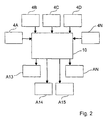
- FIG. 2 shows a simplified system outline of the preventive protection system in a block diagram
- FIG. 3 is a simplified block diagram of a signal processing means for the preventive protection system.
- FIG. 1 shows a motor vehicle 1 which can be embodied as a passenger car or as a utility vehicle, with essential components of a preventive protection system configured according to the invention.
- the preventive protection system has, as an essential component, a safety sensor system 3 which comprises a vehicle surroundings detection device 4 and a driving situation data acquisition device 5 with a driving state sensor system 6 , an impact sensor system 7 and a passenger compartment sensor system 8 .
- the components of the safety sensor system 3 can be embodied here in a known fashion, for example in one of the designs which are described in the patent documents discussed above.
- the vehicle surroundings detection device 4 here is a 24 GHz radar near-field sensor system which is known per se and has a range of approximately 20 m to 30 m, and a plurality of distance sensors. Two of the distance sensors 4 A, 4 B are shown explicitly on the front of the vehicle, and two further distance sensors 4 C, 4 D of which are shown on the rear of the vehicle, in FIG. 1 . Further distance sensors for monitoring the surroundings of the vehicle are indicated symbolically with the reference 4 N.
- the signals of the distance sensors 4 A to 4 N, as well as the signals of the other sensor systems, are processed in a data evaluation and control device 10 , the signals of the distance sensors 4 A to 4 N being processed to form information about relative distances S_rel and relative velocities v_rel to a possible collision object 2 which can be another motor vehicle, an immovable obstacle or a pedestrian, as well as information about a possible impact angle.
- the distance sensors 4 A to 4 N emit highly bundled electromagnetic waves in the form of short pulses. If they strike an object, these waves are reflected and by measuring the transit time of the pulse between the motor vehicle 1 as a transmission location and the collision object 2 as an echo location it is possible to determine the relative distance S_rel between these two objects.
- a relative velocity v_rel between the collision object 2 and the motor vehicle 1 can thus also be measured by using the Doppler effect.
- the driving state sensor system 6 analyzes important vehicle movement dynamics variables such as, for example, a vehicle velocity, wheel speeds, vehicle longitudinal acceleration and vehicle transverse acceleration, a yaw rate, spring compression travel and spring extension travel, the level of the vehicle as well as variables which are significant for the preventive protection system here, such as the accelerator pedal position, the accelerator pedal movement, the brake pedal position and the brake pedal movement as well as the steering wheel speed and the steering wheel acceleration.
- vehicle movement dynamics systems such as, for example, an anti-lock brake system and an electronic stability program, which have the function of supporting the driver in situations which are critical in terms of driving in order to avoid an accident, are activated.
- the impact sensor system 7 detects it within a few milliseconds and passes on information about the severity of the accident to the data evaluation and control device 10 . It is known to use in this context acceleration sensors, pressure sensors, intrusion sensors and contact sensors which are used to control pyrotechnic restraint systems, for example.
- the vehicle situation data acquisition device 5 is supplemented by the passenger compartment sensor system 8 which supplies information here about the status of the vehicle occupants, the vehicle occupant position and the available restraint systems as well as physiological data of the driver.
- the passenger compartment sensor system 8 which supplies information here about the status of the vehicle occupants, the vehicle occupant position and the available restraint systems as well as physiological data of the driver.
- corresponding sensors are provided in a steering wheel 12 of the motor vehicle 1 here.
- Signals are output to actuators of safety devices 13 , 14 , 15 as a function of the data evaluation by the data evaluation and control device 10 , a reversible seatbelt pretensioner 13 with an assigned actuator A 13 , a movable restraint upholstered element 14 with an assigned actuator A 14 and a means of actuating an electric seat adjustment device 15 with an associated actuator A 15 being shown here by way of example as safety devices.
- the safety devices 13 , 14 , 15 of the motor vehicle 1 are applied here in different stages as a function of the hazard level for the motor vehicle 1 .
- All the safety devices 13 , 14 , 15 , or an individual one of them, are/is activated if the information from the vehicle surroundings detection device 4 represents an anticipated collision with the collision object 2 , a remaining time TTC up to the collision being shorter than or equal to at least one of the activation time TTA of the actuators A 13 , A 14 , A 15 , AN of the associated safety devices.
- the data of the driving situation data acquisition device 5 represents a driver behavior/vehicle behavior which is predefined for a collision plausibility check.
- FIG. 3 illustrates an algorithm which compares the necessary activation time TTA of the respective actuator A 13 , A 14 , A 15 , AN with respect to the remaining time TTC up to the collision, in a highly simplified signal processing flowchart.
- the data which is acquired by the sensors 4 A, 4 B, 4 C, 4 N of the vehicle surroundings detection device 4 and which comprises the relative distance S_rel and relative velocity v_rel between the collision object 2 and the motor vehicle 1 is firstly conditioned mathematically in the data evaluation and control device 10 in order to calculate the remaining time TTC up to the collision.
- the shortest of the remaining times TTC is used for the further processing.
- a following module M 2 it is then checked whether the remaining time TTC up to the collision is longer than the necessary activation time TTA of the actuators. If this is the case, the remaining time TTC up to the collision is calculated again for each cycle. This is the state in which the vehicle approaches the collision object but there is still sufficient time to move the safety devices into the operative position.
- TTC up to the collision is shorter than or equal to at least one of the activation times TTA of the actuators.
- a module M 3 with commands is started in order to activate the actuators A 13 to AN of the assigned safety devices 13 , 14 , 15 , for example in accordance with a predefined post-cascading.
- FIG. 3 shows the simple case in which all the activation times TTA are the same, and then specifically the two interrogations explained coincide. If various activation times are to be taken into account, the interrogation in M 2 becomes more complex, as explained above.
- the triggering characteristic of the actuators is preferably configured here in such a way that the vehicle occupants are already secured prior to the collision and are placed in a seat position which is favorable for the impact, and that in addition absorption space is made available.
Abstract
Description
-
- 1000 msec for putting the backrest in an upright position,
- 500 msec for automatically initiated emergency braking in order to reduce kinetic energy (crash braking),
- 100 msec for an active headrest,
- 300 msec for active upholstery elements, and approximately
- 100 msec or more for a reversible seatbelt pretensioner,
a triggering decision which is based solely on the longest activation time is unsuitable. In a highly dynamic driving situation such as, for example, lane changing or a crossroads in particular, a collision object possibly only enters the sensing range of the vehicle surroundings detection device only very late (i.e., just before the collision). It may then be too late to trigger safety devices in good time with activation times TTA which are longer than the time TTC remaining up to the collision. According to the invention, the time TTC remaining up to the collision is classified in the series of stored activation times TTA of the actuators, which permits differentiated activation of the actuators, for example as a function of whether or not the actuator still has sufficient time TTA to generate the protective effect of the assigned safety device.
S_min=v_rel_max*(TTA+(Z*A))
i.e., from the product of a predefined maximum relative velocity v_rel_max and a time value which corresponds to the necessary activation time TTA of the actuator of an assigned safety device plus a necessary cycle time Z of the vehicle surroundings detection device multiplied by a necessary number A of sampling processes.
TTC=S_rel/v_rel
Claims (18)
Applications Claiming Priority (4)
| Application Number | Priority Date | Filing Date | Title |
|---|---|---|---|
| DE102004046360.3 | 2004-09-24 | ||
| DE102004046360.3A DE102004046360B4 (en) | 2004-09-24 | 2004-09-24 | Motor vehicle with a preventive protection system |
| DE102004046360 | 2004-09-24 | ||
| PCT/EP2005/010107 WO2006032445A2 (en) | 2004-09-24 | 2005-09-20 | Motor vehicle provided with a preventive protection system |
Publications (2)
| Publication Number | Publication Date |
|---|---|
| US20090299576A1 US20090299576A1 (en) | 2009-12-03 |
| US7873473B2 true US7873473B2 (en) | 2011-01-18 |
Family
ID=35106773
Family Applications (1)
| Application Number | Title | Priority Date | Filing Date |
|---|---|---|---|
| US11/663,500 Active 2026-06-12 US7873473B2 (en) | 2004-09-24 | 2005-09-20 | Motor vehicle having a preventive protection system |
Country Status (4)
| Country | Link |
|---|---|
| US (1) | US7873473B2 (en) |
| JP (1) | JP4874979B2 (en) |
| DE (1) | DE102004046360B4 (en) |
| WO (1) | WO2006032445A2 (en) |
Cited By (2)
| Publication number | Priority date | Publication date | Assignee | Title |
|---|---|---|---|---|
| US20100042286A1 (en) * | 2005-08-12 | 2010-02-18 | Thomas Lich | Device and Method for Side Impact Detection in a Vehicle |
| US20120259515A1 (en) * | 2009-12-02 | 2012-10-11 | Heiko Freienstein | Method for activating and/or controlling at least one reversible restraining device |
Families Citing this family (33)
| Publication number | Priority date | Publication date | Assignee | Title |
|---|---|---|---|---|
| DE102005048014A1 (en) * | 2005-10-07 | 2007-04-12 | Robert Bosch Gmbh | Driver assistance system |
| JP4306673B2 (en) * | 2005-11-08 | 2009-08-05 | トヨタ自動車株式会社 | Crew protection device |
| JP4536029B2 (en) * | 2006-03-30 | 2010-09-01 | Necアクセステクニカ株式会社 | Interconnection method and apparatus using communication protocol |
| DE102006024667B4 (en) | 2006-05-26 | 2019-07-11 | Robert Bosch Gmbh | Device and method for detecting a pedestrian impact |
| DE102007039039B4 (en) * | 2007-07-10 | 2017-12-28 | Continental Teves Ag & Co. Ohg | Control of safety means of a motor vehicle |
| JP4400634B2 (en) * | 2007-02-28 | 2010-01-20 | トヨタ自動車株式会社 | Collision prediction device |
| DE102007018470A1 (en) | 2007-04-19 | 2008-10-23 | Robert Bosch Gmbh | Driver assistance system and method for object plausibility |
| DE102007049706A1 (en) | 2007-10-17 | 2009-04-23 | Robert Bosch Gmbh | Method for estimating the relative motion of video objects and driver assistance system for motor vehicles |
| JP4706984B2 (en) * | 2009-02-25 | 2011-06-22 | トヨタ自動車株式会社 | Collision estimation apparatus and collision estimation method |
| DE102009025021A1 (en) * | 2009-06-10 | 2010-12-16 | Daimler Ag | Method for controlling a restraint device for occupants of a vehicle |
| DE102010018331A1 (en) * | 2010-04-27 | 2011-10-27 | Gm Global Technology Operations Llc (N.D.Ges.D. Staates Delaware) | Device and method for detecting a dangerous situation for a vehicle |
| DE102010052416A1 (en) | 2010-11-24 | 2012-01-05 | Daimler Ag | Method for controlling safety system for vehicle, involves predicting time of collision, depending on determined vehicle surrounding data and vehicle state parameters, where safety system is activated for predetermined time |
| DE102011077486B3 (en) * | 2011-06-14 | 2012-10-18 | Robert Bosch Gmbh | Device and method for triggering an occupant protection device, triggering system and vehicle |
| DE102011118149A1 (en) * | 2011-11-10 | 2013-05-16 | Gm Global Technology Operations, Llc | Method for operating a safety system of a motor vehicle and safety system for a motor vehicle |
| KR101338062B1 (en) * | 2011-11-15 | 2014-01-06 | 기아자동차주식회사 | Apparatus and method for managing pre-crash system for vehicle |
| DE102011120179A1 (en) * | 2011-12-06 | 2012-11-29 | Daimler Ag | Method for operating road vehicle, particularly passenger car, involves aligning two emergency brakes of road vehicle on each other such that pyrotechnical pushing unit is switched-on to increase wheel load in emergency braking situation |
| EP3040685A1 (en) * | 2011-12-29 | 2016-07-06 | INTEL Corporation | Navigation systems that enhance driver awareness |
| US8924089B2 (en) * | 2012-11-27 | 2014-12-30 | Hyundai Mobis Co., Ltd | Automobile and method of controlling automobile |
| JP5835242B2 (en) * | 2013-02-01 | 2015-12-24 | 株式会社デンソー | Vehicle safety control system |
| JP5905846B2 (en) * | 2013-03-29 | 2016-04-20 | 株式会社日本自動車部品総合研究所 | Crossing determination device and program |
| JP5783430B2 (en) | 2013-04-26 | 2015-09-24 | 株式会社デンソー | Collision mitigation device |
| US10115164B1 (en) * | 2013-10-04 | 2018-10-30 | State Farm Mutual Automobile Insurance Company | Systems and methods to quantify and differentiate individual insurance risk based on actual driving behavior and driving environment |
| EP2883744B1 (en) * | 2013-12-16 | 2021-02-17 | Volvo Car Corporation | Apparatus and method for vehicle occupant protection in large animal collisions |
| KR102322300B1 (en) * | 2014-01-29 | 2021-11-08 | 엘지이노텍 주식회사 | System for supporting safety device in vehicle |
| KR102209794B1 (en) * | 2014-07-16 | 2021-01-29 | 주식회사 만도 | Emergency braking system for preventing pedestrain and emergency braking conrol method of thereof |
| DE102014224665A1 (en) * | 2014-12-02 | 2016-06-02 | Robert Bosch Gmbh | Driver assistance control unit, motor vehicle, method for operating a driver assistance control unit of a motor vehicle |
| CN106904143B (en) * | 2015-12-23 | 2020-05-01 | 上海汽车集团股份有限公司 | Pedestrian and passenger protection method, system and controller |
| DE102016210491A1 (en) * | 2016-06-14 | 2017-12-14 | Robert Bosch Gmbh | Method for controlling a passenger protection device of a vehicle and control unit |
| US10239420B2 (en) | 2016-12-19 | 2019-03-26 | Lear Corporation | System and method for positioning a vehicle seat |
| US10817735B2 (en) | 2017-07-28 | 2020-10-27 | Google Llc | Need-sensitive image and location capture system and method |
| DE102017223222B4 (en) * | 2017-12-19 | 2020-10-22 | Zf Friedrichshafen Ag | Method for determining a trigger time of an active personal protection device and personal protection device |
| EP3953218A1 (en) * | 2019-04-08 | 2022-02-16 | ZF Friedrichshafen AG | Low impact detection for automated driving vehicles |
| US20210268974A1 (en) * | 2020-02-28 | 2021-09-02 | Lear Corporation | Electrical system |
Citations (24)
| Publication number | Priority date | Publication date | Assignee | Title |
|---|---|---|---|---|
| DE19647660A1 (en) | 1996-11-19 | 1998-05-20 | Daimler Benz Ag | Trigger device for occupant restraint systems in a vehicle |
| DE4411184C2 (en) | 1993-03-31 | 1998-06-04 | Nissan Motor | Passenger seat belt system for use with a seat mounted in a vehicle |
| DE19729960A1 (en) | 1997-07-12 | 1998-11-26 | Telefunken Microelectron | Method of detecting impacts |
| DE19724101A1 (en) | 1997-06-07 | 1998-12-10 | Bayerische Motoren Werke Ag | Process for controlling occupant safety devices as required |
| DE19813943A1 (en) | 1998-03-28 | 1999-09-30 | Telefunken Microelectron | Device for controlling restraint devices in a vehicle |
| EP0952459A2 (en) | 1998-04-23 | 1999-10-27 | Volkswagen Aktiengesellschaft | Device for detecting objects for vehicles |
| DE19822184A1 (en) | 1998-05-16 | 1999-11-18 | Volkswagen Ag | Roll sensor for detecting motor vehicle overturning |
| DE19842827A1 (en) | 1998-09-18 | 2000-03-23 | Volkswagen Ag | Pre-crash sensing system for motor vehicle displays selected regions of detected image with increased definition, magnification and/or contrast |
| DE10065518A1 (en) | 2000-12-28 | 2002-07-11 | Bosch Gmbh Robert | Method for triggering restraint devices in a motor vehicle |
| DE10121386C1 (en) | 2001-05-02 | 2002-08-29 | Daimler Chrysler Ag | Method for controlling a reversible occupant protection device in a motor vehicle |
| US20030111287A1 (en) | 2001-12-19 | 2003-06-19 | Toyota Jidosha Kabushiki Kaisha | Occupant protection system, vehicle using same and occupant protection method |
| US20030149530A1 (en) * | 2002-02-01 | 2003-08-07 | Ford Global Technologies, Inc. | Collision warning and safety countermeasure system |
| DE10212963A1 (en) | 2002-03-23 | 2003-10-02 | Bosch Gmbh Robert | Method and arrangement for the control of restraining means, in particular one which can be controlled reversibly |
| DE10231362A1 (en) | 2002-07-11 | 2004-01-22 | Robert Bosch Gmbh | Device for monitoring the environment in a vehicle |
| DE10234844A1 (en) | 2002-07-31 | 2004-02-19 | Daimlerchrysler Ag | Headrest for vehicle seat, has at least one lateral head cushion coupled to actuator drive that can be activated to move cushion to in-use position in driving situation likely to lead to accident |
| DE10246800A1 (en) | 2002-10-08 | 2004-04-22 | Robert Bosch Gmbh | Device for controlling restraining system in a vehicle, controls second airbag stage depending on combination of at least one derived criterion, impact speed that device receives from pre-crash sensing arrangement |
| DE10252180A1 (en) | 2002-11-09 | 2004-05-27 | Suspa Holding Gmbh | Active impact protection for knee/lower leg region of vehicle occupant, especially in automobile, has impact element formed by cover (impact cover) on glove compartment on front passenger side |
| WO2004058546A1 (en) | 2002-12-26 | 2004-07-15 | Denso Corporation | Safety device for motor vehicle |
| DE10303147A1 (en) | 2003-01-28 | 2004-07-29 | Robert Bosch Gmbh | Method of triggering restraint system of vehicle, employs algorithms to determine sensor signal combinations used when triggering restraint system |
| DE10309715A1 (en) | 2003-03-06 | 2004-09-16 | Robert Bosch Gmbh | Device for monitoring the front hood of a vehicle |
| US20050004719A1 (en) | 2003-06-10 | 2005-01-06 | Daimlerchrysler Ag | Device and method for determining the position of objects in the surroundings of a motor vehicle |
| DE10337620A1 (en) | 2003-08-16 | 2005-03-10 | Daimler Chrysler Ag | Vehicle, especially car, pre-safe system for adjusting vehicle suspension settings in a crash situation, whereby if a crash situation occurs, chassis and suspension are automatically adjusted to maximize occupant safety |
| US20060250297A1 (en) * | 2005-05-06 | 2006-11-09 | Ford Global Technologies, Llc | System and method for preemptively sensing an object and selectively operating both a collision countermeasure system and a parking assistance system aboard an automotive vehicle |
| US20090187290A1 (en) * | 2003-01-28 | 2009-07-23 | Toyota Jidosha Kabushiki Kaisha | Collision predicting apparatus and collision predicting method |
Family Cites Families (5)
| Publication number | Priority date | Publication date | Assignee | Title |
|---|---|---|---|---|
| JP3865182B2 (en) * | 1998-12-25 | 2007-01-10 | タカタ株式会社 | Seat belt system |
| JP4201155B2 (en) * | 2000-11-22 | 2008-12-24 | 道弘 観音寺 | Inter-vehicle distance alarm device |
| JP3632656B2 (en) * | 2001-12-11 | 2005-03-23 | トヨタ自動車株式会社 | Crew protection system |
| JP2004189078A (en) * | 2002-12-10 | 2004-07-08 | Denso Corp | Safety device for vehicle |
| JP3926748B2 (en) * | 2003-01-24 | 2007-06-06 | 本田技研工業株式会社 | Seat belt device |
-
2004
- 2004-09-24 DE DE102004046360.3A patent/DE102004046360B4/en active Active
-
2005
- 2005-09-20 WO PCT/EP2005/010107 patent/WO2006032445A2/en active Application Filing
- 2005-09-20 US US11/663,500 patent/US7873473B2/en active Active
- 2005-09-20 JP JP2007532815A patent/JP4874979B2/en active Active
Patent Citations (29)
| Publication number | Priority date | Publication date | Assignee | Title |
|---|---|---|---|---|
| DE4411184C2 (en) | 1993-03-31 | 1998-06-04 | Nissan Motor | Passenger seat belt system for use with a seat mounted in a vehicle |
| DE19647660A1 (en) | 1996-11-19 | 1998-05-20 | Daimler Benz Ag | Trigger device for occupant restraint systems in a vehicle |
| DE19724101A1 (en) | 1997-06-07 | 1998-12-10 | Bayerische Motoren Werke Ag | Process for controlling occupant safety devices as required |
| DE19729960A1 (en) | 1997-07-12 | 1998-11-26 | Telefunken Microelectron | Method of detecting impacts |
| DE19813943A1 (en) | 1998-03-28 | 1999-09-30 | Telefunken Microelectron | Device for controlling restraint devices in a vehicle |
| EP0952459A2 (en) | 1998-04-23 | 1999-10-27 | Volkswagen Aktiengesellschaft | Device for detecting objects for vehicles |
| DE19822184A1 (en) | 1998-05-16 | 1999-11-18 | Volkswagen Ag | Roll sensor for detecting motor vehicle overturning |
| DE19842827A1 (en) | 1998-09-18 | 2000-03-23 | Volkswagen Ag | Pre-crash sensing system for motor vehicle displays selected regions of detected image with increased definition, magnification and/or contrast |
| DE10065518A1 (en) | 2000-12-28 | 2002-07-11 | Bosch Gmbh Robert | Method for triggering restraint devices in a motor vehicle |
| DE10121386C1 (en) | 2001-05-02 | 2002-08-29 | Daimler Chrysler Ag | Method for controlling a reversible occupant protection device in a motor vehicle |
| US20030111287A1 (en) | 2001-12-19 | 2003-06-19 | Toyota Jidosha Kabushiki Kaisha | Occupant protection system, vehicle using same and occupant protection method |
| US20030149530A1 (en) * | 2002-02-01 | 2003-08-07 | Ford Global Technologies, Inc. | Collision warning and safety countermeasure system |
| US6721659B2 (en) * | 2002-02-01 | 2004-04-13 | Ford Global Technologies, Llc | Collision warning and safety countermeasure system |
| DE10212963A1 (en) | 2002-03-23 | 2003-10-02 | Bosch Gmbh Robert | Method and arrangement for the control of restraining means, in particular one which can be controlled reversibly |
| DE10231362A1 (en) | 2002-07-11 | 2004-01-22 | Robert Bosch Gmbh | Device for monitoring the environment in a vehicle |
| DE10234844A1 (en) | 2002-07-31 | 2004-02-19 | Daimlerchrysler Ag | Headrest for vehicle seat, has at least one lateral head cushion coupled to actuator drive that can be activated to move cushion to in-use position in driving situation likely to lead to accident |
| DE10246800A1 (en) | 2002-10-08 | 2004-04-22 | Robert Bosch Gmbh | Device for controlling restraining system in a vehicle, controls second airbag stage depending on combination of at least one derived criterion, impact speed that device receives from pre-crash sensing arrangement |
| DE10252180A1 (en) | 2002-11-09 | 2004-05-27 | Suspa Holding Gmbh | Active impact protection for knee/lower leg region of vehicle occupant, especially in automobile, has impact element formed by cover (impact cover) on glove compartment on front passenger side |
| US20050236816A1 (en) | 2002-11-09 | 2005-10-27 | Rainer Justen | Active impact protection system |
| EP1577177A1 (en) | 2002-12-26 | 2005-09-21 | Denso Corporation | Safety device for motor vehicle |
| WO2004058546A1 (en) | 2002-12-26 | 2004-07-15 | Denso Corporation | Safety device for motor vehicle |
| US7343235B2 (en) * | 2002-12-26 | 2008-03-11 | Denco Corporation | Safety device for a vehicle |
| DE10303147A1 (en) | 2003-01-28 | 2004-07-29 | Robert Bosch Gmbh | Method of triggering restraint system of vehicle, employs algorithms to determine sensor signal combinations used when triggering restraint system |
| US20090187290A1 (en) * | 2003-01-28 | 2009-07-23 | Toyota Jidosha Kabushiki Kaisha | Collision predicting apparatus and collision predicting method |
| DE10309715A1 (en) | 2003-03-06 | 2004-09-16 | Robert Bosch Gmbh | Device for monitoring the front hood of a vehicle |
| DE10326431A1 (en) | 2003-06-10 | 2005-01-13 | Daimlerchrysler Ag | Device and method for determining the position of objects in the environment of a vehicle |
| US20050004719A1 (en) | 2003-06-10 | 2005-01-06 | Daimlerchrysler Ag | Device and method for determining the position of objects in the surroundings of a motor vehicle |
| DE10337620A1 (en) | 2003-08-16 | 2005-03-10 | Daimler Chrysler Ag | Vehicle, especially car, pre-safe system for adjusting vehicle suspension settings in a crash situation, whereby if a crash situation occurs, chassis and suspension are automatically adjusted to maximize occupant safety |
| US20060250297A1 (en) * | 2005-05-06 | 2006-11-09 | Ford Global Technologies, Llc | System and method for preemptively sensing an object and selectively operating both a collision countermeasure system and a parking assistance system aboard an automotive vehicle |
Non-Patent Citations (2)
| Title |
|---|
| German Search Report dated Mar. 22, 2005 with an English translation of the pertinent portions (Eight (8) pages). |
| International Search Report dated Mar. 8, 2006 with an English translation of the pertinent portions (Fifteen (15) pages). |
Cited By (3)
| Publication number | Priority date | Publication date | Assignee | Title |
|---|---|---|---|---|
| US20100042286A1 (en) * | 2005-08-12 | 2010-02-18 | Thomas Lich | Device and Method for Side Impact Detection in a Vehicle |
| US8032275B2 (en) * | 2005-08-12 | 2011-10-04 | Robert Bosch Gmbh | Device and method for side impact detection in a vehicle |
| US20120259515A1 (en) * | 2009-12-02 | 2012-10-11 | Heiko Freienstein | Method for activating and/or controlling at least one reversible restraining device |
Also Published As
| Publication number | Publication date |
|---|---|
| JP4874979B2 (en) | 2012-02-15 |
| DE102004046360A1 (en) | 2006-03-30 |
| JP2008514474A (en) | 2008-05-08 |
| DE102004046360B4 (en) | 2014-03-27 |
| WO2006032445A2 (en) | 2006-03-30 |
| WO2006032445A3 (en) | 2006-05-04 |
| US20090299576A1 (en) | 2009-12-03 |
Similar Documents
| Publication | Publication Date | Title |
|---|---|---|
| US7873473B2 (en) | Motor vehicle having a preventive protection system | |
| US7908059B2 (en) | Motor vehicle having a preventive action protection system | |
| US20070131468A1 (en) | Motor vehicle provided with a pre-safe system | |
| US7260461B2 (en) | Method for operating a pre-crash sensing system with protruding contact sensor | |
| US7543677B2 (en) | Object detection system, protection system, and vehicle | |
| US7178622B2 (en) | Method for actuating a reversible passenger protection system in a motor vehicle | |
| US7138938B1 (en) | System and method for preemptively sensing an object and selectively operating both a collision countermeasure system and a parking assistance system aboard an automotive vehicle | |
| US8463500B2 (en) | Method for operating a pre-crash sensing system to deploy airbags using inflation control | |
| US7712776B2 (en) | Method and control system for predictive deployment of side-impact restraints | |
| US20070228705A1 (en) | Method for Operating a Pre-Crash Sensing System to Deploy Airbags Using Confidence Factors Prior to Collision | |
| WO2006052700A1 (en) | Sensor system with radar sensor and vision sensor | |
| WO2006052699A1 (en) | System for sensing impending collision and adjusting deployment of safety device | |
| US20080021617A1 (en) | Method for Actuating a Vehicle Occupant Protection Device in a Vehicle and a Vehicle Occupant Protection System | |
| GB2412471A (en) | Activation of a passive restraint system | |
| US20210284091A1 (en) | Vehicle safety system implementing integrated active-passive front impact control algorithm | |
| US20090024282A1 (en) | Method for a Preventive-Action Protection System In a Motor Vehicle Having an Inter-Vehicle Distance Sensor System | |
| JP4550825B2 (en) | Device for determining relative speed between a vehicle and a collision target | |
| CN113492786A (en) | Vehicle safety system and method implementing weighted active-passive collision mode classification | |
| US11912306B2 (en) | Low impact detection for automated driving vehicles | |
| US20080270000A1 (en) | Preventive-Action Protection System in a Motor Vehicle | |
| US11436878B2 (en) | Method for determining the severity of a possible collision between a motor vehicle and another vehicle, control apparatus, driver assistance system and a motor vehicle | |
| KR100666360B1 (en) | Apparatus for preventing car crash based on vehicle dynamics | |
| CN114981128A (en) | Passive pedestrian protection system utilizing input from active safety system |
Legal Events
| Date | Code | Title | Description |
|---|---|---|---|
| AS | Assignment |
Owner name: DAIMLER AG,GERMANY Free format text: CHANGE OF NAME;ASSIGNOR:DAIMLERCHRYSLER AG;REEL/FRAME:020976/0889 Effective date: 20071019 Owner name: DAIMLER AG, GERMANY Free format text: CHANGE OF NAME;ASSIGNOR:DAIMLERCHRYSLER AG;REEL/FRAME:020976/0889 Effective date: 20071019 |
|
| AS | Assignment |
Owner name: DAIMLERCHRYSLER AG, GERMANY Free format text: ASSIGNMENT OF ASSIGNORS INTEREST;ASSIGNORS:BAUMANN, KARL-HEINZ;FEHRING, MICHAEL;JUSTEN, RAINER;REEL/FRAME:022870/0367 Effective date: 20070320 |
|
| FEPP | Fee payment procedure |
Free format text: PAYOR NUMBER ASSIGNED (ORIGINAL EVENT CODE: ASPN); ENTITY STATUS OF PATENT OWNER: LARGE ENTITY |
|
| STCF | Information on status: patent grant |
Free format text: PATENTED CASE |
|
| FPAY | Fee payment |
Year of fee payment: 4 |
|
| MAFP | Maintenance fee payment |
Free format text: PAYMENT OF MAINTENANCE FEE, 8TH YEAR, LARGE ENTITY (ORIGINAL EVENT CODE: M1552) Year of fee payment: 8 |
|
| AS | Assignment |
Owner name: DAIMLER AG, GERMANY Free format text: CORRECTIVE ASSIGNMENT TO CORRECT THE APPLICATION NO. 10/567,810 PREVIOUSLY RECORDED ON REEL 020976 FRAME 0889. ASSIGNOR(S) HEREBY CONFIRMS THE CHANGE OF NAME;ASSIGNOR:DAIMLERCHRYSLER AG;REEL/FRAME:053583/0493 Effective date: 20071019 |
|
| MAFP | Maintenance fee payment |
Free format text: PAYMENT OF MAINTENANCE FEE, 12TH YEAR, LARGE ENTITY (ORIGINAL EVENT CODE: M1553); ENTITY STATUS OF PATENT OWNER: LARGE ENTITY Year of fee payment: 12 |