US7874616B2 - Horizontal lumbar suspension for vehicle seats - Google Patents
Horizontal lumbar suspension for vehicle seats Download PDFInfo
- Publication number
- US7874616B2 US7874616B2 US12/233,129 US23312908A US7874616B2 US 7874616 B2 US7874616 B2 US 7874616B2 US 23312908 A US23312908 A US 23312908A US 7874616 B2 US7874616 B2 US 7874616B2
- Authority
- US
- United States
- Prior art keywords
- wireframe
- pair
- side member
- lumbar
- extending
- Prior art date
- Legal status (The legal status is an assumption and is not a legal conclusion. Google has not performed a legal analysis and makes no representation as to the accuracy of the status listed.)
- Expired - Fee Related, expires
Links
Images


Classifications
-
- B—PERFORMING OPERATIONS; TRANSPORTING
- B60—VEHICLES IN GENERAL
- B60N—SEATS SPECIALLY ADAPTED FOR VEHICLES; VEHICLE PASSENGER ACCOMMODATION NOT OTHERWISE PROVIDED FOR
- B60N2/00—Seats specially adapted for vehicles; Arrangement or mounting of seats in vehicles
- B60N2/64—Back-rests or cushions
- B60N2/66—Lumbar supports
-
- B—PERFORMING OPERATIONS; TRANSPORTING
- B60—VEHICLES IN GENERAL
- B60N—SEATS SPECIALLY ADAPTED FOR VEHICLES; VEHICLE PASSENGER ACCOMMODATION NOT OTHERWISE PROVIDED FOR
- B60N2/00—Seats specially adapted for vehicles; Arrangement or mounting of seats in vehicles
- B60N2/24—Seats specially adapted for vehicles; Arrangement or mounting of seats in vehicles for particular purposes or particular vehicles
- B60N2/42—Seats specially adapted for vehicles; Arrangement or mounting of seats in vehicles for particular purposes or particular vehicles the seat constructed to protect the occupant from the effect of abnormal g-forces, e.g. crash or safety seats
- B60N2/4207—Seats specially adapted for vehicles; Arrangement or mounting of seats in vehicles for particular purposes or particular vehicles the seat constructed to protect the occupant from the effect of abnormal g-forces, e.g. crash or safety seats characterised by the direction of the g-forces
- B60N2/4214—Seats specially adapted for vehicles; Arrangement or mounting of seats in vehicles for particular purposes or particular vehicles the seat constructed to protect the occupant from the effect of abnormal g-forces, e.g. crash or safety seats characterised by the direction of the g-forces longitudinal
- B60N2/4228—Seats specially adapted for vehicles; Arrangement or mounting of seats in vehicles for particular purposes or particular vehicles the seat constructed to protect the occupant from the effect of abnormal g-forces, e.g. crash or safety seats characterised by the direction of the g-forces longitudinal due to impact coming from the rear
-
- B—PERFORMING OPERATIONS; TRANSPORTING
- B60—VEHICLES IN GENERAL
- B60N—SEATS SPECIALLY ADAPTED FOR VEHICLES; VEHICLE PASSENGER ACCOMMODATION NOT OTHERWISE PROVIDED FOR
- B60N2/00—Seats specially adapted for vehicles; Arrangement or mounting of seats in vehicles
- B60N2/24—Seats specially adapted for vehicles; Arrangement or mounting of seats in vehicles for particular purposes or particular vehicles
- B60N2/42—Seats specially adapted for vehicles; Arrangement or mounting of seats in vehicles for particular purposes or particular vehicles the seat constructed to protect the occupant from the effect of abnormal g-forces, e.g. crash or safety seats
- B60N2/427—Seats or parts thereof displaced during a crash
- B60N2/42772—Seats or parts thereof displaced during a crash characterised by the triggering system
- B60N2/42781—Seats or parts thereof displaced during a crash characterised by the triggering system mechanical triggering
-
- B—PERFORMING OPERATIONS; TRANSPORTING
- B60—VEHICLES IN GENERAL
- B60N—SEATS SPECIALLY ADAPTED FOR VEHICLES; VEHICLE PASSENGER ACCOMMODATION NOT OTHERWISE PROVIDED FOR
- B60N2/00—Seats specially adapted for vehicles; Arrangement or mounting of seats in vehicles
- B60N2/64—Back-rests or cushions
- B60N2/66—Lumbar supports
- B60N2/667—Lumbar supports having flexible support member bowed by applied forces
- B60N2/6671—Lumbar supports having flexible support member bowed by applied forces with cable actuators
-
- B—PERFORMING OPERATIONS; TRANSPORTING
- B60—VEHICLES IN GENERAL
- B60N—SEATS SPECIALLY ADAPTED FOR VEHICLES; VEHICLE PASSENGER ACCOMMODATION NOT OTHERWISE PROVIDED FOR
- B60N2/00—Seats specially adapted for vehicles; Arrangement or mounting of seats in vehicles
- B60N2/64—Back-rests or cushions
- B60N2/66—Lumbar supports
- B60N2/667—Lumbar supports having flexible support member bowed by applied forces
- B60N2/6673—Lumbar supports having flexible support member bowed by applied forces with motor driven adjustments
-
- B—PERFORMING OPERATIONS; TRANSPORTING
- B60—VEHICLES IN GENERAL
- B60N—SEATS SPECIALLY ADAPTED FOR VEHICLES; VEHICLE PASSENGER ACCOMMODATION NOT OTHERWISE PROVIDED FOR
- B60N2/00—Seats specially adapted for vehicles; Arrangement or mounting of seats in vehicles
- B60N2/80—Head-rests
- B60N2/888—Head-rests with arrangements for protecting against abnormal g-forces, e.g. by displacement of the head-rest
Definitions
- Embodiments of the invention relate to lumbar suspensions for vehicle seats.
- Prior art vehicle seats are provided with horizontal lumbar suspensions.
- Prior art vehicle seats are also provided with active head restraint systems.
- An example of a vehicle seat with a horizontal lumbar suspension and an active head restraint system is disclosed in U.S. Pat. No. 6,837,541 B2, which issued on Jan. 4, 2005.
- FIG. 1 is a front side perspective view of a seat back of a vehicle seat according to embodiments of the invention, illustrated with a lumbar assembly;
- FIG. 2 is a front side perspective view of the lumbar assembly of FIG. 1 ;
- FIG. 3 is a front side elevation view of the lumbar assembly of FIG. 1 ;
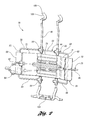
- FIG. 4 is a section view taken along section line 4 - 4 in FIG. 3 ;
- FIG. 5 is an enlarged paritial section view taken along section line 5 - 5 in FIG. 3 .
- the vehicle seat includes a seat cushion (not shown) that is adapted to be installed within an interior of a vehicle, such as an automobile, aircraft, water craft or the like, for seating an occupant.
- the seat back 10 is also installed in the vehicle for supporting the back of an occupant.
- the seat back 10 may be mounted directly to the vehicle or connected to the seat cushion.
- an individual seat is depicted in FIG. 1
- the invention contemplates any seat configuration, such as a bench seat, a split frame seat, a front row seat, a rear row seat, or the like.
- the seat cushion and the seat back 10 are both fabricated from suitable and known materials and manufacturing methods.
- the seat cushion may utilize a structural frame, foam for cushioning, and a covering.
- the seat back 10 extends from the seat cushion.
- the seat also includes a head restraint 12 extending above the seat back 10 for supporting the head of the occupant against the head restraint 12 .
- the seat back 10 is illustrated with a cover and padding removed for depicting internal components.
- the seat back 10 includes a frame 14 for providing structural support for the seat back 10 .
- the seat back 10 includes a horizontally actuatable lumbar suspension 16 for providing support to the occupant, while providing adjustability so that the occupant can select the desired level of comfort and support.
- the seat back frame 14 includes a pair of laterally spaced apart side supports 20 , 22 that are each mounted to lateral ends of an upper cross support 24 and a lower cross support 26 .
- the lumbar suspension 16 includes a flexible lumbar support band 28 mounted to a wireframe 30 .
- the lumbar suspension 16 is an input for an active head restraint system 18 .
- the wireframe 30 is connected to the seat frame 14 and to the active head restraint system 18 .
- the active head restraint system 18 has a pair of links 32 each pivotally connected to one of the side supports 20 , 22 .
- a pair of extension springs 34 are each connected to one of the links 32 and the corresponding side supports 20 , 22 to urge the links 32 to a design position which is illustrated in FIG. 1 .
- An armature 36 is pivotally connected to each of the links 32 .
- a pair of posts 38 extend upright from the armature 36 and extend through the upper cross support 24 .
- a pair of sleeves 40 are each provided within one of the posts 38 for receiving a pair of rods 42 , which extend from the head restraint 12 and cooperate with the sleeves 40 for height adjustment of the head restraint 12 relative to the seat back 10 .
- the wireframe 30 includes a laterally extending cross member 44 for supporting the support band 28 .
- the wireframe 30 also includes a pair of upright wires 46 for mounting the lumbar suspension 16 to the frame 14 and to the active head restraint system 18 .
- a cross wire 48 is mounted to a lower end of the upright wires 46 and extends through a pair of guides 50 on the lower cross support 26 .
- the guides 50 each include a slot 52 which receives the cross wire 48 and is inclined in a rearward direction.
- the guides 50 provide a pivotal connection of the lumbar suspension 16 with the frame 14 while also permitting the lower end of the lumbar suspension 16 to translate upward and rearward in response to an impact condition.
- the upper ends of the upright wires 46 are pivotally connected to the armature 36 so that an input force to the lumbar suspension 16 during an impact condition actuates the armature 36 upward and rearward.
- the actuation of the armature 36 causes the links 32 to pivot relative to the side supports 22 , as the armature 36 translates upward and rearward and pivots in a forward direction.
- This motion of the armature 36 thereby extends the posts 38 upward from the upper cross support 24 , and pivots the posts 38 in a forward direction such that the head restraint 12 is actuated upward and forward for moving the head restraint 12 closer to the occupant's head in an impact condition.
- the extension springs 34 return the links 32 , and consequently the active head restraint system 18 and the lumbar suspension 16 , to the design position illustrated in FIG. 1 .
- the lumbar suspension 16 actuates the active head restraint system for moving the head restraint 12 closer to the head of the occupant for minimizing whiplash during an impact condition.
- the input force may be generated, for example, when the vehicle impacts another object thereby accelerating the seat into the occupant.
- Such an impact condition may be generated from a rear impact.
- the impact condition may be generated from a forward impact wherein the occupant rebounds from a seat harness or other mechanism, into the seat.
- the lumbar suspension 16 demonstrates a suitable horizontally actuatable lumbar suspension 16 that can be utilized in combination with an active head restraint system 18 .
- the cross member 44 of the wireframe 30 includes a central region 53 that is connected to the pair of upright wires 46 by overmolded connectors 54 .
- the cross member 44 also includes a pair of lateral regions 56 , 58 extending outboard from the central region 53 that are canted in a forward direction.
- a pair of side members 60 , 62 extend downward from the lateral regions 56 , 58 of the cross member 44 .
- a second pair of lateral regions 64 , 66 extend inward from lower ends of each of the side members 60 , 62 and are connected to the upright wires 46 , by a pair of overmolded connectors 54 .
- the support band 28 includes a pair of outboard portions 68 , 70 that are each affixed to one of the side members 60 , 62 of the wireframe 30 .
- a pair of lateral portions 72 , 74 are each pivotally connected to one of the outboard portions 68 , 70 and extend laterally inboard towards a central region of the support band 28 .
- a central portion 76 of the lumbar support band 28 extends across the central region and is pivotally connected to both of the lateral portions 72 , 74 .
- a cable assembly 78 is provided for adjusting a position of the support band 28 in a fore/aft direction of the vehicle seat.
- the cable assembly 78 may be a Bowden cable that includes a sheath 80 connected to the lumbar support band outboard portion 70 .
- An internal cable 82 extends from the sheath 80 behind the support band 28 and is affixed to the other lumbar support band outboard portion 68 .
- the cable assembly 78 is connected to an actuator 84 that is mounted on the seat frame 14 and is manually or electrically operated.
- Operation of the actuator 84 retracts the cable 82 within the sheath 80 thereby pivoting the lumbar support band lateral portions 72 , 74 in a fore/aft direction while also translating the central portion 76 in the fore/aft direction.
- the support band 28 is illustrated in a full rearward orientation and a full forward orientation.
- the support band 28 is oriented in a design position, absent any loading from the cable assembly 78 .
- the central portion 76 extends across the upright wires 46 and the lateral portions 72 , 74 are canted in a forward direction to extend to the outboard portion 68 , 70 on the side members 60 , 62 of the wireframe 30 .
- the lumbar support band 28 is flexed in the forward direction as illustrated by the full forward position.
- the cable 82 is extended from the sheath 80 and the lumbar support band 28 unflexes and retracts towards the unloaded or free rearward position.
- an additional sheath 86 may be provided about the cable 82 rearward of the lumbar support band central portion 76 to prevent friction between the cable 82 and the lumbar support band 28 .
- the lumbar support band 28 is insert-molded onto the side members 60 , 62 of the wireframe 30 . Therefore, the side members 60 , 62 do not provide a pivotal connection for the lumbar support band 28 . Accordingly, a pair of hinges 88 , 90 are each provided laterally inboard from the corresponding side members 60 , 62 . Referring now to FIG. 5 , one of the hinges 88 is illustrated in greater detail.
- the hinge 88 is provided by a series of grooves 92 formed in opposed sides of the lumbar support band 28 for weakening a portion of the lumbar support band 28 for providing the pivotal connection between the lateral portion 72 and the outboard portion 68 .
- each structural enhancement is provided by a first segment 94 extending in a forward direction from the side member 60 .
- a second segment 96 extends laterally inboard from the first segment 94 .
- a third segment 98 extends in a rearward direction from the second segment 96 and connects to the hinge 88 .
- the first, second and third segments 94 , 96 , 98 collectively form a channel 100 that is bridged incrementally by a series of ribs 102 ( FIGS. 3 and 5 ).
- the segments 94 , 96 , 98 and the ribs 102 collectively provide structural enhancement to the lumbar support band 28 between the attachment to the side member 60 and the hinge 88 for controlled and predictable actuation of the lumbar support band 28 for extension and retraction for controlling lumbar support.
- the hinges 88 , 90 are provided within the material of the support band 28 , as opposed to pivoting about the side members 60 , 62 , so that the lumbar support band 28 can be insert-molded directly onto the wireframe 30 , thereby eliminating a manufacturing step of assembling the support band 28 onto the wireframe 30 .
- the lumbar suspension 16 can be fabricated by forming the wireframe 30 , then insert-molding the lumbar support band 28 upon the wireframe 30 . Additional features of the suspension 16 can be concurrently co-molded with the lumbar support band 28 .
- the connectors 54 may be co-molded with the lumbar support band 28 .
- a connector 104 for connecting the cross wire 48 to the upright wires 46 may be co-molded during this process.
- An upper end of the upright wires 46 each include a hook 106 for connecting to the armature 36 .
- Each of the hooks 106 may be co-molded in the molding process with a cover 108 for providing a damper between the upright wires 46 and the armature 36 and for eliminating any buzz, squeak and rattle therebetween.
- the invention contemplates utilization of the lumbar support band 28 in a fixed system that does not provide adjustment.
- the lumbar suspension 16 may be provided without the cable assembly 78 and the actuator 84 .
- the hinges 88 , 90 provide compliancy in the lumbar support band 28 .
- the structural enhancements between the hinges 88 , 90 and the attachments to the side members 60 , 62 provide a rigid connection between the outboard portions 68 , 70 of the lumbar support band 28 to the wireframe side members 60 , 62 for controlled compliancy.
- the lumbar support band central portion 76 may be molded with connectors 110 about the upright wires 46 as illustrated in phantom in FIG. 4 .
Abstract
Description
Claims (20)
Priority Applications (3)
| Application Number | Priority Date | Filing Date | Title |
|---|---|---|---|
| US12/233,129 US7874616B2 (en) | 2008-09-18 | 2008-09-18 | Horizontal lumbar suspension for vehicle seats |
| DE102009035430A DE102009035430A1 (en) | 2008-09-18 | 2009-07-31 | Horizontal lumbar support for vehicle seats |
| CN2009101739024A CN101676146B (en) | 2008-09-18 | 2009-09-17 | Horizontal lumbar suspension for vehicle seats |
Applications Claiming Priority (1)
| Application Number | Priority Date | Filing Date | Title |
|---|---|---|---|
| US12/233,129 US7874616B2 (en) | 2008-09-18 | 2008-09-18 | Horizontal lumbar suspension for vehicle seats |
Publications (2)
| Publication Number | Publication Date |
|---|---|
| US20100066136A1 US20100066136A1 (en) | 2010-03-18 |
| US7874616B2 true US7874616B2 (en) | 2011-01-25 |
Family
ID=42006548
Family Applications (1)
| Application Number | Title | Priority Date | Filing Date |
|---|---|---|---|
| US12/233,129 Expired - Fee Related US7874616B2 (en) | 2008-09-18 | 2008-09-18 | Horizontal lumbar suspension for vehicle seats |
Country Status (3)
| Country | Link |
|---|---|
| US (1) | US7874616B2 (en) |
| CN (1) | CN101676146B (en) |
| DE (1) | DE102009035430A1 (en) |
Cited By (8)
| Publication number | Priority date | Publication date | Assignee | Title |
|---|---|---|---|---|
| US20090322127A1 (en) * | 2008-06-27 | 2009-12-31 | Johnson Controls Technology Company | Actuator for crash activated head restraint |
| US20100237676A1 (en) * | 2009-03-17 | 2010-09-23 | Orzelski Zbigniew J | Active head restraint having multiple horizontal pivot points |
| US20150274042A1 (en) * | 2012-03-14 | 2015-10-01 | Ts Tech Co., Ltd. | Vehicle seat |
| US20150335161A1 (en) * | 2014-05-20 | 2015-11-26 | Jörg Schwarzbich | Lordosis Support |
| US20180035809A1 (en) * | 2014-05-20 | 2018-02-08 | Jörg Schwarzbich | Lordosis Support |
| JP2019059479A (en) * | 2013-09-18 | 2019-04-18 | テイ・エス テック株式会社 | Vehicle seat |
| US20190118679A1 (en) * | 2013-09-18 | 2019-04-25 | Ts Tech Co., Ltd. | Vehicle seat |
| DE102023100406A1 (en) | 2022-04-01 | 2023-10-05 | Lear Corporation | Vehicle seat subassemblies |
Families Citing this family (24)
| Publication number | Priority date | Publication date | Assignee | Title |
|---|---|---|---|---|
| WO2008073285A1 (en) * | 2006-12-08 | 2008-06-19 | Johnson Controls Technology Company | Vehicle seat with lumbar support |
| ATE499234T1 (en) * | 2008-12-17 | 2011-03-15 | Fiat Ricerche | LUMBAR SUPPORT FOR VEHICLE BACKREST |
| US8668266B2 (en) * | 2010-07-12 | 2014-03-11 | Ford Global Technologies, Llc | Integrated lumbar for thin seat |
| US8439441B2 (en) | 2010-09-29 | 2013-05-14 | Lear Corporation | Adjustable lumbar assembly for vehicle seats |
| DE112011103321T5 (en) * | 2010-09-30 | 2013-07-11 | Ts Tech Co., Ltd. | vehicle seat |
| DE102012009543A1 (en) * | 2012-05-11 | 2013-11-14 | Johnson Controls Gmbh | Seat spring mat for a vehicle seat and vehicle seat |
| US9649963B2 (en) * | 2014-03-04 | 2017-05-16 | Ford Global Technologies, Pllc | Trim and foam assembly for a vehicle seat |
| EP2939569B1 (en) * | 2014-05-02 | 2018-03-28 | Schukra Gerätebau GmbH | Method of producing a lumbar support device, lumbar support device and vehicle seat |
| US10306990B2 (en) | 2014-05-19 | 2019-06-04 | Milsco Manufacturing Company, A Unit Of Jason Incorporated | Adjustable seat occupant support assembly |
| KR101664651B1 (en) * | 2015-01-16 | 2016-10-10 | 현대자동차주식회사 | Seat for vehicle having improved passenger' neck injury reduction performance |
| WO2016122439A1 (en) * | 2015-01-26 | 2016-08-04 | Kongsberg Automotive, Inc. | Adjustment mechanism for a seat |
| JP6200036B2 (en) * | 2016-05-23 | 2017-09-20 | テイ・エス テック株式会社 | Vehicle seat |
| US10166900B2 (en) | 2017-02-09 | 2019-01-01 | Ford Global Technologies, Llc | Internal upper seatback support for driving and sleeper seats |
| US10065535B1 (en) * | 2017-03-02 | 2018-09-04 | Ford Global Technologies, Llc | Seatback lift mechanism for a supine motor vehicle seating assembly |
| US10569674B2 (en) | 2017-03-02 | 2020-02-25 | Ford Global Technologies, Llc | Mechanism for a supine motor vehicle seating assembly |
| US10166887B2 (en) | 2017-03-02 | 2019-01-01 | Ford Global Technologies, Llc | Seatback lift mechanism for a supine motor vehicle seating assembly |
| US10434905B2 (en) | 2017-03-02 | 2019-10-08 | Ford Global Technologies, Llc | Collapsible lift mechanism for H-point lift |
| US10081270B1 (en) | 2017-03-03 | 2018-09-25 | Ford Global Technologies, Llc | Front seat sleeper seat and features |
| US10525861B2 (en) | 2017-03-22 | 2020-01-07 | Ford Global Technologies, Llc | Leg support options for sleeper seats |
| US10286815B2 (en) | 2017-04-03 | 2019-05-14 | Ford Global Technologies, Llc | H-point lift options for sleeper seats |
| DE102017220077A1 (en) * | 2017-11-10 | 2019-05-16 | Lear Corporation | Carrying device for a vehicle seat assembly |
| US10632873B2 (en) | 2018-04-04 | 2020-04-28 | Ford Global Technologies, Llc | Seat structure dual motion recliner pivot mechanism |
| US11007908B2 (en) | 2019-06-25 | 2021-05-18 | Ford Global Technologies, Llc | Upper thoracic support paddle attachment assembly |
| KR20230015637A (en) * | 2021-07-23 | 2023-01-31 | 주식회사 디에스시동탄 | Lumber support assembly |
Citations (20)
| Publication number | Priority date | Publication date | Assignee | Title |
|---|---|---|---|---|
| EP0420824A1 (en) | 1989-09-28 | 1991-04-03 | FIAT AUTO S.p.A. | A backrest for a seat, particularly a motor-vehicle seat |
| EP0537839A1 (en) | 1991-10-18 | 1993-04-21 | CLERPREM S.p.A. | A support member for seats useful, for example, as a lumbar support member in the backrests of automobile vehicle seats |
| US5462335A (en) | 1994-08-18 | 1995-10-31 | Perfection Spring & Stamping Corp. | Adjustable lumbar support for seat backs |
| US5769490A (en) * | 1993-12-24 | 1998-06-23 | Henderson's Industries Pty. Ltd. | Adjustable lumbar support |
| US5823620A (en) | 1997-04-17 | 1998-10-20 | Lear Corporation | Vehicle seat having lumbar support |
| US5954399A (en) * | 1998-07-15 | 1999-09-21 | Hong; Jung-Myung | Lumbar support for a car seat |
| US6375262B1 (en) * | 2000-03-14 | 2002-04-23 | Ikeda Bussan Co., Ltd. | Automotive seat-back structure |
| US6644740B2 (en) | 2000-06-28 | 2003-11-11 | Lear Corporation | Vehicle seat lumbar support system |
| US20040178670A1 (en) * | 1998-06-05 | 2004-09-16 | Schukra Geratebau Ag | Support with adjustable arch, especially a lumbar support for any type of seat or bed |
| US6837541B2 (en) | 2002-09-30 | 2005-01-04 | Lear Corporation | Vehicle seat having a lumbar support system |
| US6883867B2 (en) | 1993-06-17 | 2005-04-26 | Schukra Geratebau Ag | Device for adjusting a flexible support element of a backrest |
| US6908153B2 (en) | 2002-12-02 | 2005-06-21 | L&P Property Management Company | Power lumbar support cable apparatus and method |
| US6918634B2 (en) | 2003-07-22 | 2005-07-19 | Henderson's Industries Pty Ltd | Lumbar support |
| US7083232B2 (en) | 2002-11-01 | 2006-08-01 | L&P Property Management Company | Massage apparatus and method for lumbar support |
| US7097247B2 (en) | 2003-06-05 | 2006-08-29 | Steelcase Development Corporation | Seating unit with adjustable lumbar device |
| US7131694B1 (en) * | 2005-04-29 | 2006-11-07 | Buffa John A | Adjustable lumbar support for vehicle seat |
| US7252335B2 (en) | 2004-03-12 | 2007-08-07 | L&P Property Management Company | Lumbar with flexwires in cross |
| US7328950B2 (en) * | 2005-05-18 | 2008-02-12 | Schukra Of North America, Ltd. | Dual hinge belt lumbar |
| US20090102255A1 (en) | 2007-10-22 | 2009-04-23 | Lear Corporation | Motor vehicle seat |
| US7585027B2 (en) * | 2006-04-07 | 2009-09-08 | Schukra Of North America | Overmolded thin-profile lumbar support |
-
2008
- 2008-09-18 US US12/233,129 patent/US7874616B2/en not_active Expired - Fee Related
-
2009
- 2009-07-31 DE DE102009035430A patent/DE102009035430A1/en not_active Withdrawn
- 2009-09-17 CN CN2009101739024A patent/CN101676146B/en not_active Expired - Fee Related
Patent Citations (22)
| Publication number | Priority date | Publication date | Assignee | Title |
|---|---|---|---|---|
| EP0420824A1 (en) | 1989-09-28 | 1991-04-03 | FIAT AUTO S.p.A. | A backrest for a seat, particularly a motor-vehicle seat |
| EP0537839A1 (en) | 1991-10-18 | 1993-04-21 | CLERPREM S.p.A. | A support member for seats useful, for example, as a lumbar support member in the backrests of automobile vehicle seats |
| US6883867B2 (en) | 1993-06-17 | 2005-04-26 | Schukra Geratebau Ag | Device for adjusting a flexible support element of a backrest |
| US5769490A (en) * | 1993-12-24 | 1998-06-23 | Henderson's Industries Pty. Ltd. | Adjustable lumbar support |
| US5462335A (en) | 1994-08-18 | 1995-10-31 | Perfection Spring & Stamping Corp. | Adjustable lumbar support for seat backs |
| US5823620A (en) | 1997-04-17 | 1998-10-20 | Lear Corporation | Vehicle seat having lumbar support |
| US20040178670A1 (en) * | 1998-06-05 | 2004-09-16 | Schukra Geratebau Ag | Support with adjustable arch, especially a lumbar support for any type of seat or bed |
| US5954399A (en) * | 1998-07-15 | 1999-09-21 | Hong; Jung-Myung | Lumbar support for a car seat |
| US6375262B1 (en) * | 2000-03-14 | 2002-04-23 | Ikeda Bussan Co., Ltd. | Automotive seat-back structure |
| US6644740B2 (en) | 2000-06-28 | 2003-11-11 | Lear Corporation | Vehicle seat lumbar support system |
| US6837541B2 (en) | 2002-09-30 | 2005-01-04 | Lear Corporation | Vehicle seat having a lumbar support system |
| US7128372B2 (en) | 2002-09-30 | 2006-10-31 | Lear Corporation | Vehicle seat having a lumbar support system |
| US6991288B2 (en) | 2002-09-30 | 2006-01-31 | Lear Corporation | Vehicle seat having a lumbar support system |
| US7083232B2 (en) | 2002-11-01 | 2006-08-01 | L&P Property Management Company | Massage apparatus and method for lumbar support |
| US6908153B2 (en) | 2002-12-02 | 2005-06-21 | L&P Property Management Company | Power lumbar support cable apparatus and method |
| US7097247B2 (en) | 2003-06-05 | 2006-08-29 | Steelcase Development Corporation | Seating unit with adjustable lumbar device |
| US6918634B2 (en) | 2003-07-22 | 2005-07-19 | Henderson's Industries Pty Ltd | Lumbar support |
| US7252335B2 (en) | 2004-03-12 | 2007-08-07 | L&P Property Management Company | Lumbar with flexwires in cross |
| US7131694B1 (en) * | 2005-04-29 | 2006-11-07 | Buffa John A | Adjustable lumbar support for vehicle seat |
| US7328950B2 (en) * | 2005-05-18 | 2008-02-12 | Schukra Of North America, Ltd. | Dual hinge belt lumbar |
| US7585027B2 (en) * | 2006-04-07 | 2009-09-08 | Schukra Of North America | Overmolded thin-profile lumbar support |
| US20090102255A1 (en) | 2007-10-22 | 2009-04-23 | Lear Corporation | Motor vehicle seat |
Cited By (17)
| Publication number | Priority date | Publication date | Assignee | Title |
|---|---|---|---|---|
| US8727437B2 (en) * | 2008-06-27 | 2014-05-20 | Johnson Controls Technology Company | Actuator for crash activated head restraint |
| US20090322127A1 (en) * | 2008-06-27 | 2009-12-31 | Johnson Controls Technology Company | Actuator for crash activated head restraint |
| US20100237676A1 (en) * | 2009-03-17 | 2010-09-23 | Orzelski Zbigniew J | Active head restraint having multiple horizontal pivot points |
| US7959224B2 (en) * | 2009-03-17 | 2011-06-14 | Ford Global Technologies, Llc | Active head restraint having multiple horizontal pivot points |
| US20150274042A1 (en) * | 2012-03-14 | 2015-10-01 | Ts Tech Co., Ltd. | Vehicle seat |
| US9751434B2 (en) * | 2012-03-14 | 2017-09-05 | Ts Tech Co., Ltd. | Vehicle seat |
| US10493877B2 (en) | 2012-03-14 | 2019-12-03 | Ts Tech Co., Ltd. | Vehicle seat |
| US10752136B2 (en) * | 2013-09-18 | 2020-08-25 | Ts Tech Co., Ltd. | Vehicle seat |
| US11780352B2 (en) | 2013-09-18 | 2023-10-10 | Ts Tech Co., Ltd. | Vehicle seat |
| US11390197B2 (en) | 2013-09-18 | 2022-07-19 | Ts Tech Co., Ltd. | Vehicle seat |
| JP2019059479A (en) * | 2013-09-18 | 2019-04-18 | テイ・エス テック株式会社 | Vehicle seat |
| US20190118679A1 (en) * | 2013-09-18 | 2019-04-25 | Ts Tech Co., Ltd. | Vehicle seat |
| US20180035809A1 (en) * | 2014-05-20 | 2018-02-08 | Jörg Schwarzbich | Lordosis Support |
| US10568433B2 (en) * | 2014-05-20 | 2020-02-25 | Jörg Schwarzbich | Lordosis support |
| US9814318B2 (en) * | 2014-05-20 | 2017-11-14 | Jörg Schwarzbich | Lordosis support |
| US20150335161A1 (en) * | 2014-05-20 | 2015-11-26 | Jörg Schwarzbich | Lordosis Support |
| DE102023100406A1 (en) | 2022-04-01 | 2023-10-05 | Lear Corporation | Vehicle seat subassemblies |
Also Published As
| Publication number | Publication date |
|---|---|
| CN101676146A (en) | 2010-03-24 |
| CN101676146B (en) | 2013-03-06 |
| US20100066136A1 (en) | 2010-03-18 |
| DE102009035430A1 (en) | 2010-12-02 |
Similar Documents
| Publication | Publication Date | Title |
|---|---|---|
| US7874616B2 (en) | Horizontal lumbar suspension for vehicle seats | |
| US8439441B2 (en) | Adjustable lumbar assembly for vehicle seats | |
| US7857381B2 (en) | Active head restraint system with lumbar support for vehicle seats | |
| US7850235B2 (en) | Active head restraint system with actuating system for a vehicle seat | |
| US8727374B1 (en) | Vehicle seatback with side airbag deployment | |
| CN105857119B (en) | Beneficial assembly of seat back and cushion | |
| US7975360B2 (en) | Head restraint support component for a vehicle seat | |
| US7699394B2 (en) | Connections for active head restraint systems for vehicle seats | |
| US6672666B2 (en) | Mesh seat with displaceable bolsters | |
| US7992933B2 (en) | Integrated vehicle seat with active head restraint system | |
| US8820832B2 (en) | Active head restraint with wiring pass-through | |
| US20080129092A1 (en) | Cushion Plate With Pressure Adjusting Mechanism In Use For Vehicle Seat | |
| WO2012086803A1 (en) | Vehicle seat | |
| US7984945B2 (en) | Reduced thickness vehicle seat with active headrest | |
| WO2008004678A1 (en) | Vehicle seat | |
| US10836290B2 (en) | Vehicle seat | |
| WO2007123219A1 (en) | Vehicle seat | |
| US9663009B2 (en) | Conveyance seat | |
| CN101370689A (en) | Support element with adjustable lateral supports | |
| US10583759B2 (en) | Vehicle seat | |
| US20170217337A1 (en) | Vehicle seat strap retaining assembly | |
| US20100237676A1 (en) | Active head restraint having multiple horizontal pivot points | |
| CN107933389B (en) | Seat suspension with maximized downward deflection feature | |
| US9802516B2 (en) | Vehicle seat strap retaining assembly | |
| CN207737147U (en) | Lower armchair structure |
Legal Events
| Date | Code | Title | Description |
|---|---|---|---|
| AS | Assignment |
Owner name: LEAR CORPORATION,MICHIGAN Free format text: ASSIGNMENT OF ASSIGNORS INTEREST;ASSIGNOR:D'AGOSTINI, ROBERTO;REEL/FRAME:021558/0859 Effective date: 20080918 Owner name: LEAR CORPORATION, MICHIGAN Free format text: ASSIGNMENT OF ASSIGNORS INTEREST;ASSIGNOR:D'AGOSTINI, ROBERTO;REEL/FRAME:021558/0859 Effective date: 20080918 |
|
| AS | Assignment |
Owner name: JPMORGAN CHASE BANK, N.A., AS ADMINISTRATIVE AGENT Free format text: GRANT OF FIRST LIEN SECURITY INTEREST IN PATENT RIGHTS;ASSIGNOR:LEAR CORPORATION;REEL/FRAME:023519/0267 Effective date: 20091109 Owner name: JPMORGAN CHASE BANK, N.A., AS ADMINISTRATIVE AGENT Free format text: GRANT OF SECOND LIEN SECURITY INTEREST IN PATENT RIGHTS;ASSIGNOR:LEAR CORPORATION;REEL/FRAME:023519/0626 Effective date: 20091109 |
|
| STCF | Information on status: patent grant |
Free format text: PATENTED CASE |
|
| CC | Certificate of correction | ||
| AS | Assignment |
Owner name: JPMORGAN CAHSE BANK, N.A., AS AGENT, ILLINOIS Free format text: SECURITY INTEREST;ASSIGNOR:LEAR CORPORATION;REEL/FRAME:030076/0016 Effective date: 20130130 Owner name: JPMORGAN CHASE BANK, N.A., AS AGENT, ILLINOIS Free format text: SECURITY INTEREST;ASSIGNOR:LEAR CORPORATION;REEL/FRAME:030076/0016 Effective date: 20130130 |
|
| AS | Assignment |
Owner name: LEAR CORPORATION, MICHIGAN Free format text: RELEASE BY SECURED PARTY;ASSIGNOR:JPMORGAN CHASE BANK, N.A.;REEL/FRAME:032770/0843 Effective date: 20100830 |
|
| FPAY | Fee payment |
Year of fee payment: 4 |
|
| SULP | Surcharge for late payment | ||
| AS | Assignment |
Owner name: LEAR CORPORATION, MICHIGAN Free format text: RELEASE BY SECURED PARTY;ASSIGNOR:JPMORGAN CHASE BANK, N.A., AS AGENT;REEL/FRAME:037701/0340 Effective date: 20160104 Owner name: LEAR CORPORATION, MICHIGAN Free format text: RELEASE BY SECURED PARTY;ASSIGNOR:JPMORGAN CHASE BANK, N.A., AS AGENT;REEL/FRAME:037701/0251 Effective date: 20160104 Owner name: LEAR CORPORATION, MICHIGAN Free format text: RELEASE BY SECURED PARTY;ASSIGNOR:JPMORGAN CHASE BANK, N.A., AS AGENT;REEL/FRAME:037701/0180 Effective date: 20160104 |
|
| AS | Assignment |
Owner name: LEAR CORPORATION, MICHIGAN Free format text: RELEASE BY SECURED PARTY;ASSIGNOR:JPMORGAN CHASE BANK, N.A., AS AGENT;REEL/FRAME:037702/0911 Effective date: 20160104 |
|
| MAFP | Maintenance fee payment |
Free format text: PAYMENT OF MAINTENANCE FEE, 8TH YEAR, LARGE ENTITY (ORIGINAL EVENT CODE: M1552) Year of fee payment: 8 |
|
| FEPP | Fee payment procedure |
Free format text: MAINTENANCE FEE REMINDER MAILED (ORIGINAL EVENT CODE: REM.); ENTITY STATUS OF PATENT OWNER: LARGE ENTITY |
|
| LAPS | Lapse for failure to pay maintenance fees |
Free format text: PATENT EXPIRED FOR FAILURE TO PAY MAINTENANCE FEES (ORIGINAL EVENT CODE: EXP.); ENTITY STATUS OF PATENT OWNER: LARGE ENTITY |
|
| STCH | Information on status: patent discontinuation |
Free format text: PATENT EXPIRED DUE TO NONPAYMENT OF MAINTENANCE FEES UNDER 37 CFR 1.362 |
|
| FP | Lapsed due to failure to pay maintenance fee |
Effective date: 20230125 |