US7881395B2 - Method of transmitting using phase shift-based precoding and an apparatus for implementing the same in a wireless communication system - Google Patents
Method of transmitting using phase shift-based precoding and an apparatus for implementing the same in a wireless communication system Download PDFInfo
- Publication number
- US7881395B2 US7881395B2 US11/858,082 US85808207A US7881395B2 US 7881395 B2 US7881395 B2 US 7881395B2 US 85808207 A US85808207 A US 85808207A US 7881395 B2 US7881395 B2 US 7881395B2
- Authority
- US
- United States
- Prior art keywords
- matrix
- precoding matrix
- phase shift
- spatial multiplexing
- precoding
- Prior art date
- Legal status (The legal status is an assumption and is not a legal conclusion. Google has not performed a legal analysis and makes no representation as to the accuracy of the status listed.)
- Active, expires
Links
Images


Classifications
-
- H—ELECTRICITY
- H04—ELECTRIC COMMUNICATION TECHNIQUE
- H04B—TRANSMISSION
- H04B7/00—Radio transmission systems, i.e. using radiation field
- H04B7/02—Diversity systems; Multi-antenna system, i.e. transmission or reception using multiple antennas
- H04B7/04—Diversity systems; Multi-antenna system, i.e. transmission or reception using multiple antennas using two or more spaced independent antennas
- H04B7/06—Diversity systems; Multi-antenna system, i.e. transmission or reception using multiple antennas using two or more spaced independent antennas at the transmitting station
- H04B7/0613—Diversity systems; Multi-antenna system, i.e. transmission or reception using multiple antennas using two or more spaced independent antennas at the transmitting station using simultaneous transmission
- H04B7/0667—Diversity systems; Multi-antenna system, i.e. transmission or reception using multiple antennas using two or more spaced independent antennas at the transmitting station using simultaneous transmission of delayed versions of same signal
- H04B7/0671—Diversity systems; Multi-antenna system, i.e. transmission or reception using multiple antennas using two or more spaced independent antennas at the transmitting station using simultaneous transmission of delayed versions of same signal using different delays between antennas
-
- H—ELECTRICITY
- H04—ELECTRIC COMMUNICATION TECHNIQUE
- H04B—TRANSMISSION
- H04B7/00—Radio transmission systems, i.e. using radiation field
- H04B7/02—Diversity systems; Multi-antenna system, i.e. transmission or reception using multiple antennas
-
- H—ELECTRICITY
- H04—ELECTRIC COMMUNICATION TECHNIQUE
- H04B—TRANSMISSION
- H04B7/00—Radio transmission systems, i.e. using radiation field
- H04B7/01—Reducing phase shift
-
- H—ELECTRICITY
- H04—ELECTRIC COMMUNICATION TECHNIQUE
- H04L—TRANSMISSION OF DIGITAL INFORMATION, e.g. TELEGRAPHIC COMMUNICATION
- H04L1/00—Arrangements for detecting or preventing errors in the information received
- H04L1/0001—Systems modifying transmission characteristics according to link quality, e.g. power backoff
- H04L1/0002—Systems modifying transmission characteristics according to link quality, e.g. power backoff by adapting the transmission rate
- H04L1/0003—Systems modifying transmission characteristics according to link quality, e.g. power backoff by adapting the transmission rate by switching between different modulation schemes
-
- H—ELECTRICITY
- H04—ELECTRIC COMMUNICATION TECHNIQUE
- H04L—TRANSMISSION OF DIGITAL INFORMATION, e.g. TELEGRAPHIC COMMUNICATION
- H04L1/00—Arrangements for detecting or preventing errors in the information received
- H04L1/0001—Systems modifying transmission characteristics according to link quality, e.g. power backoff
- H04L1/0009—Systems modifying transmission characteristics according to link quality, e.g. power backoff by adapting the channel coding
-
- H—ELECTRICITY
- H04—ELECTRIC COMMUNICATION TECHNIQUE
- H04L—TRANSMISSION OF DIGITAL INFORMATION, e.g. TELEGRAPHIC COMMUNICATION
- H04L25/00—Baseband systems
- H04L25/02—Details ; arrangements for supplying electrical power along data transmission lines
- H04L25/03—Shaping networks in transmitter or receiver, e.g. adaptive shaping networks
- H04L25/03006—Arrangements for removing intersymbol interference
- H04L25/03343—Arrangements at the transmitter end
-
- H—ELECTRICITY
- H04—ELECTRIC COMMUNICATION TECHNIQUE
- H04L—TRANSMISSION OF DIGITAL INFORMATION, e.g. TELEGRAPHIC COMMUNICATION
- H04L5/00—Arrangements affording multiple use of the transmission path
- H04L5/0001—Arrangements for dividing the transmission path
- H04L5/0014—Three-dimensional division
- H04L5/0023—Time-frequency-space
-
- H—ELECTRICITY
- H04—ELECTRIC COMMUNICATION TECHNIQUE
- H04L—TRANSMISSION OF DIGITAL INFORMATION, e.g. TELEGRAPHIC COMMUNICATION
- H04L1/00—Arrangements for detecting or preventing errors in the information received
- H04L1/0001—Systems modifying transmission characteristics according to link quality, e.g. power backoff
- H04L1/0023—Systems modifying transmission characteristics according to link quality, e.g. power backoff characterised by the signalling
- H04L1/0026—Transmission of channel quality indication
-
- H—ELECTRICITY
- H04—ELECTRIC COMMUNICATION TECHNIQUE
- H04L—TRANSMISSION OF DIGITAL INFORMATION, e.g. TELEGRAPHIC COMMUNICATION
- H04L1/00—Arrangements for detecting or preventing errors in the information received
- H04L1/12—Arrangements for detecting or preventing errors in the information received by using return channel
- H04L1/16—Arrangements for detecting or preventing errors in the information received by using return channel in which the return channel carries supervisory signals, e.g. repetition request signals
- H04L1/18—Automatic repetition systems, e.g. Van Duuren systems
- H04L1/1812—Hybrid protocols; Hybrid automatic repeat request [HARQ]
- H04L1/1816—Hybrid protocols; Hybrid automatic repeat request [HARQ] with retransmission of the same, encoded, message
-
- H—ELECTRICITY
- H04—ELECTRIC COMMUNICATION TECHNIQUE
- H04L—TRANSMISSION OF DIGITAL INFORMATION, e.g. TELEGRAPHIC COMMUNICATION
- H04L25/00—Baseband systems
- H04L25/02—Details ; arrangements for supplying electrical power along data transmission lines
- H04L25/03—Shaping networks in transmitter or receiver, e.g. adaptive shaping networks
- H04L25/03006—Arrangements for removing intersymbol interference
- H04L2025/0335—Arrangements for removing intersymbol interference characterised by the type of transmission
- H04L2025/03375—Passband transmission
- H04L2025/03414—Multicarrier
-
- H—ELECTRICITY
- H04—ELECTRIC COMMUNICATION TECHNIQUE
- H04L—TRANSMISSION OF DIGITAL INFORMATION, e.g. TELEGRAPHIC COMMUNICATION
- H04L25/00—Baseband systems
- H04L25/02—Details ; arrangements for supplying electrical power along data transmission lines
- H04L25/03—Shaping networks in transmitter or receiver, e.g. adaptive shaping networks
- H04L25/03006—Arrangements for removing intersymbol interference
- H04L2025/0335—Arrangements for removing intersymbol interference characterised by the type of transmission
- H04L2025/03426—Arrangements for removing intersymbol interference characterised by the type of transmission transmission using multiple-input and multiple-output channels
-
- Y—GENERAL TAGGING OF NEW TECHNOLOGICAL DEVELOPMENTS; GENERAL TAGGING OF CROSS-SECTIONAL TECHNOLOGIES SPANNING OVER SEVERAL SECTIONS OF THE IPC; TECHNICAL SUBJECTS COVERED BY FORMER USPC CROSS-REFERENCE ART COLLECTIONS [XRACs] AND DIGESTS
- Y02—TECHNOLOGIES OR APPLICATIONS FOR MITIGATION OR ADAPTATION AGAINST CLIMATE CHANGE
- Y02D—CLIMATE CHANGE MITIGATION TECHNOLOGIES IN INFORMATION AND COMMUNICATION TECHNOLOGIES [ICT], I.E. INFORMATION AND COMMUNICATION TECHNOLOGIES AIMING AT THE REDUCTION OF THEIR OWN ENERGY USE
- Y02D30/00—Reducing energy consumption in communication networks
- Y02D30/50—Reducing energy consumption in communication networks in wire-line communication networks, e.g. low power modes or reduced link rate
Definitions
- the present invention relates to a method of transmitting, and more particularly, to a method of transmitting using phase shift-based precoding and an apparatus for implementing the same in a wireless communication system.
- W-CDMA wideband code division multiple access
- MIMO multi-input, multi-output
- 3GPP 3 rd Generation Partnership Project
- the two (2) antenna system adopted in Release 99 and Release 4, based on transmit diversity has been improved to a new type of diversity scheme, such as a per antenna rate control (PARC) or a per user unitary rate control (PU2RC), which considers operation using more than three (3) antennas.
- PARC per antenna rate control
- PU2RC per user unitary rate control
- FIG. 1A is an exemplary diagram illustrating a structure of a PARC for a single user.
- FIG. 1B is an exemplary diagram illustrating a structure of a PARC for multiple users.
- each transmit antenna can be configured using the same modulation and encoding without feedback information from channel quality information (CQI).
- CQI channel quality information
- the PARC uses the feedback information regarding the channel conditions, such as a modulation coding set (MCS) and/or a transmit antenna subset (TAS), and selects the user data stream to be transmitted by each antenna.
- MCS modulation coding set
- TAS transmit antenna subset
- any one of the three (3) user data streams is selected since this is an exemplary illustration the PARC for single user.
- at least two (2) of the three (3) user data streams are selected since this is an exemplary illustration the PARC for multiple users.
- the modulation and encoding using the feedback information regarding the channel conditions is applied to the user data streams stored in the buffer after being demultiplexed.
- the user data streams are then multiplexed using a scheme (e.g., orthogonal frequency division multiple access (OFDMA)) and transmitted via each antenna.
- a scheme e.g., orthogonal frequency division multiple access (OFDMA)
- a base station (BS) applying the PARC scheme uses the feedback information transmitted from a mobile station (MS) to perform scheduling for optimizing transmission rate.
- MS mobile station
- the PARC scheme allows for increase in diversity gain as a number of MSs scheduled by the BS increases.
- the feedback overhead is reduced since only the CQI is used as the feedback information.
- the CQI is used as the feedback information.
- there is relatively less possibility of error during the feedback process and switching can take place between the PARC for the single user and the PARC for the multiple users.
- the PARC for multiple users interference between users can occur thus affecting transmission efficiency.
- FIG. 2 is an exemplary diagram illustrating a structure of a PU2RC.
- the PU2RC uses spatial multiplexing for transmitting data streams of multiple users. As such, multiple data streams are selected for transmission to multiple users.
- a unitary matrix based on a singular value decomposition of the MIMO channel is used to perform precoding.
- the unitary matrix in a transmitter is a set of unitary basic vectors selected by all users (or MSs). If the set of vectors is fixed, represented by M, the unitary basic vectors are selected by one or multiple users.
- the PU2RC can be used to reduce inter-user interference and achieve high efficiency gain.
- the feedback information size can be large since information can include preferred matrix index in addition preferred vector in the matrix, thus increasing the possibility of transmission error due to the large size of the feedback information
- the present invention is directed to a method of transmitting using phase shift-based precoding and an apparatus for implementing the same in a wireless communication system that substantially obviates one or more problems due to limitations and disadvantages of the related art.
- An object of the present invention is to provide a method of transmitting data using a plurality of subcarriers in a multi-antenna wireless communication system.
- Another object of the present invention is to provide a transmitting and receiving device in a multi-user, multi-antenna communication system using a plurality of subcarriers.
- a method of transmitting data using a plurality of subcarriers in a multi-antenna wireless communication system includes receiving feedback information from a mobile station (MS), performing channel encoding and modulation independently on user data to be transmitted by each antenna using the received feedback information, determining a phase shift-based precoding matrix for increasing a phase angle of the user data by a fixed amount, and performing precoding using the determined phase shift-based precoding matrix on the user data.
- MS mobile station
- a transmitting and receiving device in a multi-user, multi-antenna communication system using a plurality of subcarriers includes a channel encoder and modulator configured to perform channel coding and modulation independently on user data for each antenna using feedback information from the receiving device, and a first precoder configured to determine a phase shift-based precoding matrix and to perform precoding on the user data using the determined phase shift-based precoding matrix, wherein the phase shift-based precoding matrix is determined based on increasing a phase angle of the user data for each antenna fixedly.
- FIG. 1A is an exemplary diagram illustrating a structure of a PARC for a single user
- FIG. 1B is an exemplary diagram illustrating a structure of a PARC for multiple users
- FIG. 2 is an exemplary diagram illustrating a structure of a PU2RC
- FIG. 3A is an exemplary diagram illustrating a transmitter of a communication system according to Embodiment #1;
- FIGS. 3B and 3C are exemplary diagrams illustrating processes or procedures of the precoder of the transmitter of FIG. 3A ;
- FIG. 4 is an exemplary diagram illustrating phase shift-based precoding
- FIG. 5 is an exemplary diagram illustrating change in channel size as a result of cyclic delay
- FIG. 6 is an exemplary diagram illustrating a multiple antenna system, having four (4) transmit antennas and the spatial multiplexing rate of 2, to which a conventional spatial multiplexing and cyclic delay diversity schemes are applied;
- FIG. 7 is an exemplary diagram of a multiple antenna system to which the phase shift-based precoding matrix of Equation 10 is applied;
- FIG. 8 is an exemplary diagram of a four-antenna system where a specific part of the precoding matrix is selected
- FIG. 9 is an exemplary diagram illustrating a transmitter according to the Embodiment #2.
- FIG. 10 is an exemplary diagram illustrating a process of a transmitter and a receiver in a multi-antenna system which supports codebook-based precoding
- FIG. 11A is an exemplary diagram illustrating a comparison between a conventional PARC and the method of the present invention in an environment where there is no spatial correlation in an ITU PedA channel;
- FIG. 11B is an exemplary diagram illustrating a comparison between a conventional PARC and the method of the present invention in an environment where the spatial correlation is 70%;
- FIG. 12A is an exemplary diagram illustrating a comparison between a conventional PARC and the method of the present invention in a TU channel having high frequency selection
- FIG. 12B is another exemplary diagram illustrating a comparison between a conventional PARC and the method of the present invention in a TU channel having high frequency selection.
- the discussions related to the present invention can be applied in various wireless communication systems.
- the wireless communication system can be used to provide services related to voice, audio, packet data, etc.
- the discussions to follow can be used in downlink as well as uplink transmissions.
- the downlink transmission refers to transmission from a BS to a MS
- the uplink transmission refers to transmission from the MS to the BS.
- the BS can be generally referred to a fixed station and can also be referred to as Node B, a base transceiver system (BTS), an access point (AP), a network, and a serving station, among other names.
- the MS can be mobile and/or fixed and can be referred to as a user equipment (UE), a user terminal (UT), a subscriber station (SS), a mobile subscriber station (MSS), a mobile terminal (MT), and a wireless device, among other names.
- a multi-carrier system can use various modulation schemes, such as an orthogonal frequency division multiplexing (OFDM) and an orthogonal frequency division multiple access (OFDMA).
- OFDM/OFDMA is a scheme in which the bandwidths of the entire system are partitioned into a plurality of subcarriers having orthogonality.
- the subcarriers can also be referred to as a subband or a tone.
- the single-carrier system can use various modulation schemes including a single-carrier frequency division multiple access (SC-CDMA) or a code division multiple access (CDMA).
- a communication system comprises a transmitter and a receiver.
- a unit or a module which can perform the functions of the transmitter and the receiver can be referred to as a transceiver.
- the transmitter and the receiver can be independently used.
- the transmitter can be a part of the BS, and the receiver can be a part of the MS.
- the transmitter can be a part of the MS while the receiver can be a part of the BS.
- the BS can include a plurality of transmitters and/or receivers.
- the MS can include a plurality of transmitters and/or receivers.
- This embodiment relates to optimizing the transmission efficiency by independently configuring modulation and encoding of each transmission antenna in a multi-user, multi-antenna system.
- a phase shift-based precoding can be applied to minimize or reduce interference between users.
- FIG. 3A is an exemplary diagram illustrating a transmitter of a communication system according to Embodiment #1.
- the transmitter 100 comprises a scheduler/multiplexer 110 , a plurality of channel encoders/modulators ( 120 - 1 ⁇ 120 -N), a precoder 130 , a plurality of serial/parallel (SP) converters ( 140 - 1 ⁇ 140 -N t ), a plurality of modulators ( 150 - 1 ⁇ 150 -N t ).
- SP serial/parallel
- FIGS. 3B and 3C are exemplary diagrams illustrating processes or procedures of the precoder of the transmitter of FIG. 3A .
- the scheduler/multiplexer 110 can be configured to schedule the user (or the MS) when the streams of information bits are inputted by each user. From the scheduled users, the actual user for transmission can be selected, and the selected information bits can be multiplexed.
- the plurality of channel encoders/modulators ( 120 - 1 ⁇ 120 -N) can be configured to output coded data by encoding the multiplexed information bits according to a prescribed coding scheme(s). Thereafter, the coded data can be modulated using a prescribed modulation scheme.
- the information bits can include text, audio, video, or other types of data.
- the plurality of channel encoders/modulators can attach or add an error detection bits (e.g., cyclic redundancy check (CRC)) to the information bits and further add extra codes for error correction.
- the error correction codes include a turbo code, a low density parity check code (LDPC), and a convolution code, among other various error correction codes.
- the plurality of channel encoders/modulators can be configured to map (or allocate) the coded data to symbols on an amplitude and phase constellation.
- the modulation schemes that can be applied are not limited and can vary, and these schemes can be an m-quadrature phase shift keying (m-PSK) scheme or a m-quadrature amplitude modulation (m-QAM) scheme.
- m-PSK m-quadrature phase shift keying
- m-QAM m-quadrature amplitude modulation
- the m-PSK scheme includes a binary phase shift keying (BPSK), a quadrature phase shift keying (QPSK), or an 8-PSK.
- the m-QAM includes a 16-QAM, a 64-QAM, or a 256-QAM.
- the precoder 130 can be configured to apply phase shift-based precoding to the mapped symbols.
- the precoder 130 can output a transmit symbol which is a set of symbols transmitted during one transmission period or one time slot. The details of the phase shift-based precoding performed by the precoder 130 will be discussed later.
- the plurality of S/P converters ( 140 - 1 ⁇ 140 -N t ) can be configured to output the precoded transmit symbols in parallel to the plurality of modulators ( 150 - 1 ⁇ 150 -N t ).
- the plurality of modulators ( 150 - 1 ⁇ 150 -N t ) can be configured to modulate each transmit symbols from the S/P converters ( 140 - 1 ⁇ 140 -N t ) according to a multiple access modulation scheme.
- the multiple access modulation schemes that can be applied are not limited, and these schemes can be a single-carrier modulation scheme (e.g., CDMA) or a multi-carrier modulation scheme (e.g., OFDMA).
- phase shift-based precoding scheme applied in a two-antenna system and/or a four-antenna system using OFDM multi-carrier modulation scheme.
- the discussions relate to application of the phase shift-based precoding to a multi-antenna system having N t number of antennas. More specifically, the discussions may be based on a structure of a generalized phase shift-based precoding matrix which can be applied to enhancing the multi-antenna system having N t number of antennas.
- FIG. 4 is an exemplary diagram illustrating phase shift-based precoding.
- the phase shift-based precoding can be defined as a scheme by which the data streams are transmitted via all the antennas but with different (or independent) phase sequence multiplied thereto.
- a frequency selection of a channel is provided from the perspective of the receiver (e.g., MS), and the size of the channel can increase or decrease depending on the frequency domain.
- FIG. 5 is an exemplary diagram illustrating change in channel size as a result of cyclic delay.
- the transmitter 100 can achieve frequency diversity by allocating users (or MSs) to parts of the frequency whose channel condition improves due to increase in frequency of the frequency domain.
- certain parts of the frequency domain has a large frequency bandwidth and is less affected by fluctuations caused by relative small cyclic delay values.
- the phase shift-based precoding matrix, P can be used as expressed as in Equation 1.
- k denotes index of subcarriers or frequency resource index in which a specific frequency bandwidth is allocated for each resource
- the complex weight value can be variable according to the index of the OFDM symbols and corresponding subcarriers multiplied to antennas.
- the complex weight value can be determined by channel condition and/or feedback information.
- the precoding matrix, P, of Equation 1 is configured using a unitary matrix so as to reduce loss in channel capacity of a multi-antenna system.
- the following equation can be used to express a channel capacity of a multi-antenna open-loop system so as to define the elements (or components) of the unitary matrix.
- Equation 2 H denotes a multi-antenna channel matrix having a size of N r ⁇ N t , and N r denotes a number of receiving antennas. If Equation 2 is applied to the phase shift-based precoding matrix P, the result can be expressed as shown in Equation 3.
- phase shift-based precoding matrix P In order for the phase shift-based precoding matrix P to be converted to an identity matrix, two (2) conditions need to be satisfied. That is, a power limitation condition and orthogonality limitation condition need to be met simultaneously.
- the power limitation condition relates to making the size of each column of the matrix to equal 1.
- the orthogonality limitation condition relates to making each column orthogonal (or the columns are orthogonal to each other). Equation 5 and Equation 6 are examples of these.
- Equations 2-6 relate to a unitary matrix.
- the discussions of the unitary matrix relate to a phase shift-based precoding matrix having a 2 ⁇ 2 matrix size.
- Equation 7 represents a general phase shift-based precoding matrix applied in a system having a spatial multiplexing rate of 2 and two (2) transmit antennas.
- k denotes subcarrier index or resource index of OFDM signals.
- Equation 7 In order to convert such a precoding matrix (e.g., Equation 7) into a unit matrix, the power limitation condition of Equation 8 and the orthogonality limitation condition of Equation 9 need to be satisfied.
- Equation 8 * denotes a conjugate complex number. If the phase shift-based precoding matrix having a size of 2 ⁇ 2 satisfies Equations 7-9, such a matrix can be expressed as follows as shown in Equation 10.
- Equation 11 Equation 11
- the precoding matrix can be stored in the transmitter and the receiver in a form of a codebook.
- the codebook can include various precoding matrix generated using a specified number of different ⁇ 2 values.
- ⁇ 2 value can be configured based on the channel conditions and whether feedback information is provided or not. If the feedback information is provided (or used), ⁇ 2 value can be configured to be a small value. If the feedback information is not provided (or not used), ⁇ 2 value can be configured to be a large value so as to attain high frequency diversity gain.
- the multiplexing rate R may have to be set low in view of actual number of antennas due to the channel condition.
- a specified number of columns corresponding to a current spatial multiplexing rate (e.g., reduced spatial multiplexing rate) from the generated phase shift-based precoding matrix can be selected to reconfigure the phase shift-based precoding matrix.
- a new precoding matrix to be applied to the corresponding system is not generated each time the spatial multiplexing rate is changed. Rather, the initial (or first generated) phase shift-based precoding matrix can continue to be used, and a specified column of the corresponding precoding matrix can be selected to reconfigure the precoding matrix.
- the multi-antenna communication system comprises two (2) transmit antennas, and the spatial multiplexing rate is 2.
- the spatial multiplexing rate can change and can be reduced to 1.
- a column from the precoding matrix of Equation 10 can be selected and the selected column can be used for precoding.
- phase shift-based precoding matrix can be expressed as shown in Equation 12.
- this form of equation is analogous to the form where cyclic delay diversity scheme is applied in a two (2) transmit antenna system.
- Equation 12 an exemplary illustration associated with a system having two (2) transmit antennas. However, this equation can also be applied to a system having four (4) transmit antennas. In other words, in a four (4) transmit antenna system, after the phase shift-based precoding matrix is generated, a specified column can be selected in accordance with the changing spatial multiplexing rate (e.g., spatial multiplexing rate from 2 to 1), and the selected specified column can be used for precoding.
- the changing spatial multiplexing rate e.g., spatial multiplexing rate from 2 to 1
- FIG. 6 is an exemplary diagram illustrating a multiple antenna system, having four (4) transmit antennas and the spatial multiplexing rate of 2, to which a conventional spatial multiplexing and cyclic delay diversity schemes are applied.
- FIG. 7 is an exemplary diagram of a multiple antenna system to which the phase shift-based precoding matrix of Equation 10 is applied.
- a first sequence S 1 and a second sequence S 2 are sent to a first antenna (e.g., ANT#1) and a third antenna (e.g., ANT#3), respectively.
- a phase shifted first sequence (s 1 e j ⁇ 1 ) and a phase shifted second sequence (s 2 e j ⁇ 1 ) are sent to a second antenna (e.g., ANT#2) and a fourth antenna (e.g., ANT#4), respectively.
- the spatial multiplexing rate is 2.
- a sequence s 1 +s 2 e jk ⁇ 2 is sent to the first antenna (e.g., ANT#1), a sequence s 1 e jk ⁇ 3 +s 2 is sent to the third antenna (e.g., ANT#3), a sequence s 1 e jk ⁇ 1 +s 2 e jk( ⁇ 1 + ⁇ 2 ) is sent to the second antenna (e.g., ANT#2), and a sequence s 1 e jk( ⁇ 1 + ⁇ 1 ) +s 2 e jk ⁇ 1 is sent to the fourth antenna (e.g., ANT#4).
- the first antenna e.g., ANT#1
- a sequence s 1 e jk ⁇ 3 +s 2 is sent to the third antenna (e.g., ANT#3)
- a sequence s 1 e jk ⁇ 1 +s 2 e jk( ⁇ 1 + ⁇ 2 ) is sent to the second antenna (e.g., ANT#
- the system of FIG. 7 uses a unitary precoding matrix to perform cyclic delay (or phase shift) on four (4) antennas so as to take advantage of the cyclic delay diversity scheme.
- phase shift-based precoding matrix per spatial multiplexing rate in a two (2) antenna system and a four (4) antenna system can be organized as follows.
- Table 1 Each of the four (4) types of precoding matrices shown in Table 1 can be acquired by selecting a specific part of the precoding matrix from the four (4) antenna system having the spatial multiplexing rate of 2. This is illustrated in FIG. 8 which is an exemplary diagram of a four-antenna system where a specific part of the precoding matrix is selected.
- each of the four (4) precoding matrix as shown in Table 1, does not need to be separately or independently provided in the codebook.
- the phase shift-based precoding matrix as discussed above, can be applied to a system having M number of antennas with the multiplexing rate of N (N ⁇ M) based on the same logic.
- the first precoder 130 comprises a precoding matrix generation module 131 - 1 , a matrix reconfiguration module 133 - 1 , and a precoding module 134 - 1 . More specifically, the precoding matrix generation module 131 - 1 can be configured to determine a reference row corresponding to a first subcarrier from a prescribed precoding matrix, and to perform phase shift to determine remaining rows. Here, phase shifting is based on increasing the phase angle of the reference row by a constant or uniform amount.
- the precoding can be performed using a unitary matrix having a specified size (e.g., (number of transmit antennas) ⁇ (spatial multiplexing rate)).
- the unitary matrix can be provided to index of each subcarrier or index resource, and the unitary matrix for the first index can be phase shifted so that the unitary matrix for the rest of the indices can be determined.
- the precoding matrix generation module 131 - 1 can select an arbitrary first precoding matrix from the codebook stored in the memory.
- the second precoding matrix for the subcarriers of the second index can be generated by applying a small phase shift to the first precoding matrix.
- the amount of phase shift can be determined based on the channel condition and/or whether feedback information is received or not.
- the third precoding matrix for the subcarriers of the third index can be generated by applying a small phase shift to the second precoding matrix.
- the rest of the precoding matrices up to the last precoding matrix can be generated according to the processes described above.
- the matrix reconfiguration module 133 - 1 can be configured to select a specified number of columns corresponding to the spatial multiplexing rate (e.g., 1 or 2) of each precoding matrix generated from the precoding matrix generation module 131 - 1 , and to discard remaining (or non-selected) columns in reconfiguring the precoding matrix.
- precoding matrix can be generated based on only the selected column.
- an arbitrary column can be selected as the specified column from the precoding matrix, or the specific column can be selected according to a prescribed scheme.
- the precoding module 134 - 1 can be configured to perform precoding by substituting or assigning OFDM symbols corresponding to the subcarriers to each of the determined precoding matrix.
- phase shift-based precoding matrix can be expressed as shown in Equation 14.
- ⁇ can be pre-set with two (2) values and the information regarding the pre-set values can be fed back in form of codebook index. For example, if the feedback codebook index is 0, ⁇ can be 0.2, and if the feedback codebook index is 1, then ⁇ can be 0.8. Such values can be predetermined and shared between the transmitter and the receiver. In addition, each column can be allocated to different user(s).
- a prescribed precoding matrix can be used to achieve signal-to-noise (SNR) diversity gain.
- SNR signal-to-noise
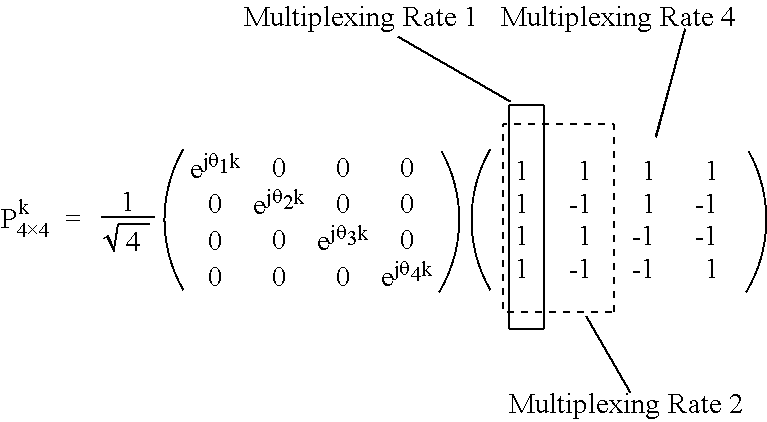
- the phase shift-based precoding matrix P can be expressed as shown in Equation 15.
- Equation 15 this is based on a system having four (4) transmit antennas and a spatial multiplexing rate of 4.
- the second matrix to the right of the equal sign e.g., represented in 1s and ⁇ 1s
- can be reconfigured to select a specific antenna e.g., antenna selection
- spatial multiplexing rate e.g., rate tuning
- Equation 16 represents reconfigured unit matrix for selecting two (2) antennas in a system having four (4) transmit or virtual antennas.
- the spatial multiplexing rate can change or vary due to various factors including affects in time and/or channel conditions.
- Table 2 shows a method for reconfiguring the second matrix to the right of the equal sign (e.g., represented by 0s, 1s, and ⁇ 1s) to correspond to the changed (or changing) spatial multiplexing rate.
- the first column, the first and second columns, and/or first through fourth columns are selected according to the multiplexing rate (e.g., multiplexing rate of 1, 2, or 4).
- the multiplexing rate (or selection of columns) is not limited to the example of Table 2, but the multiplexing rate can be one (1) and any one of the four columns can be selected.
- the multiplexing rate is two (2), any two columns of the four columns (e.g., 1 - 2 , 2 - 3 , 3 - 4 , or 4 - 1 ) can be selected.
- one or more column(s) in the matrix in Table 2 can be allocated to different user(s) in order to share spatial domain resource(s).
- the second matrix can be provided to the transmitter and the receiver in a form of a codebook.
- the transmitter can receive the index information of the codebook from the receiver. Thereafter, the transmitter can select a unitary matrix (e.g., the second matrix) of the corresponding index from the codebook and use Equation 13 to configure the phase shift-based precoding matrix.
- the cyclic delay value for phase shift-based precoding matrix can be a value that is predetermined at the transmitter and the receiver. Alternatively, this value can be a value that is provided to the transmitter via the feedback information.
- the spatial multiplexing rate R can be a predetermined value at the transmitter and the receiver. However, the spatial multiplexing rate R can be provided as feedback information by the receiver to the transmitter after the receiver calculates the spatial multiplexing rate upon periodically measuring the channel conditions.
- the transmitter can use the channel information fed back from the receiver to calculate and/or manipulate the spatial multiplexing rate.
- Korean Application No. 2006-97216 filed on Oct. 2, 2006
- Korean Application No. 2007-37008 filed on Apr. 16, 2007, can be referred to, which are hereby incorporated by reference.
- a first precoder 130 comprises a precoding matrix determining module 131 - 2 , an antenna selection module 132 , a matrix reconfiguration module 133 - 2 , and a precoding module 134 - 2 .
- the precoding matrix determining module 131 - 2 can be configured to determine a phase shift-based precoding matrix by multiplying the second matrix which satisfies the conditions associated with the first matrix (e.g., Equation 13) and the unitary matrix.
- the antenna selection module 132 can be configured to select at least one partial matrix having a size of n ⁇ n (0 ⁇ n ⁇ N) corresponding to a specific antenna from the second matrix (e.g., Equation 16), and select a specific antenna to be used for data transmission by configuring all elements other than the selected element to zero (0).
- the selected element e.g., Equation 16
- the matrix reconfiguration module 133 - 2 can be configured to select a number of columns corresponding to the spatial multiplexing rate of the second matrix (e.g., Table 2) and to reconfigure the second matrix using only the selected columns.
- the second matrix e.g., Table 2
- a memory (not shown) can be used to store various information
- a receiver circuit (not shown) can be used to receive feedback information
- a controller (not shown) can be used to control various components of the transmitter.
- the memory can store a codebook for the phase shift-based precoding matrix and/or a modulation and coding scheme (MCS) lookup table for supporting adaptive channel coding and modulation (AMC) scheme.
- the codebook can include at least one item associated with the phase shift-based precoding matrix and at least one item associated with each matrix index.
- the MCS lookup table can include at least one item associated with coding rate to be applied to the inputted information bits, at least one item associated with modulation scheme, and at least one item associated with MCS level index.
- the receiver circuit can receive the transmitted signals from the receiver via the antenna, converts the received signals into digital signal, and send the digitally converted signals to the controller.
- the received signals can include information such as channel quality information (CQI).
- CQI channel quality information
- the CQI can be included in feedback information and can be used to provide information related to channel condition, coding scheme(s), and/or modulation scheme(s). More specifically, the CQI can be associated with index for the phase shift-based precoding matrix, index for a specific coding rate and/or modulation scheme or modulation size. As index information, the MCS level index can be used.
- precoding based on a codebook can be used to schedule transmit power more efficiently so as to increase transmit reliability as well as transmit throughput. Moreover, such a method can be implement in a transmitter and a receiver.
- FIG. 9 is an exemplary diagram illustrating a transmitter according to the Embodiment #2.
- the transmitter 100 comprises a scheduler/multiplexer 110 , a plurality of channel encoders/modulators ( 120 - 1 ⁇ 120 -N), a precoder 130 , a plurality of serial/parallel (SP) converters ( 140 - 1 ⁇ 140 -N t ), a plurality of modulators ( 150 - 1 ⁇ 150 -N t ).
- SP serial/parallel
- the transmitter 200 comprises a scheduler/multiplexer 210 , a plurality of channel encoders/modulators ( 220 - 1 ⁇ 220 -N), a precoder 240 , a plurality of serial/parallel (SP) converters ( 250 - 1 ⁇ 250 -N t ), a plurality of modulators ( 260 - 1 ⁇ 260 -N t ).
- a precoder based on codebook 230 is further included.
- Precoding # 2 relates to a scheme by which SNR gain can be achieved by receiving as feedback from the receiver an index of the precoding matrix, known to both the transmitter and the receiver.
- FIG. 10 is an exemplary diagram illustrating a process of a transmitter and a receiver in a multi-antenna system which supports codebook-based precoding.
- the transmitter and the receiver each have a fixed precoding matrix (P 1 ⁇ P L ).
- the receiver can use the channel information to transmit as feedback to the transmitter an optimum precoding matrix index l.
- the precoder 240 of the transmitter can then apply the precoding matrix corresponding to the index to the transmit data (X 1 ⁇ X Mt ).
- Table 3 shows an example of a codebook that can be applied in a system having two (2) transmit antennas with the spatial multiplexing rate of 2, and the system uses 3-bit feedback information.
- the transmitter can receive periodically information of the preferred precoding index of the receiver, the CQI, and the frequency bandwidth having the best or acceptable channel condition. Having such feedback information as basis, the transmitter can use the same precoding index and can perform scheduling of preferred data stream(s) to different receivers (e.g., MSs) on the same frequency and the same time frame.
- the memory (not shown) of Embodiment #2 can include more codebooks for precoding compared to that of Embodiment #1.
- the receiver circuit (not shown) of Embodiment #2 can receive more information associated with codebook index for selecting precoding matrix from the codebook compared to that of Embodiment #1.
- the transmitter and the receiver with respect to Embodiments #1 and #2 can include an interleaver (not shown) for performing interleaving by parsing code bits so as to minimize loss caused by noise in transmitting data. Moreover, an inverse fast Fourier transform (IFFT) (not shown) can be included for allocating the precoded transmit symbols to the subcarriers in the time domain. In addition, the transmitter and the receiver with respect to Embodiments #1 and #2 can also include a filter (not shown) for converting the transmit symbols to high frequency signals, and an analog converter (not shown).
- IFFT inverse fast Fourier transform
- Table 4 shows the results of the simulation or the test.
- FIG. 11A is an exemplary diagram illustrating a comparison between a conventional PARC and the method of the present invention in an environment where there is no spatial correlation in an ITU PedA channel.
- FIG. 11B is an exemplary diagram illustrating a comparison between a conventional PARC and the method of the present invention in an environment where the spatial correlation is 70%.
- the throughput according to the present invention is always higher than the transmit method of PARC, regardless of the spatial correlation of the transmitter and the receiver. Furthermore, the difference is noticeably amplified as the spatial correlation of the transmitter and the receiver is increased. That is, the overall transmit capability is increased due to decrease in multi-user interference.
- FIG. 12A is an exemplary diagram illustrating a comparison between a conventional PARC and the method of the present invention in a TU channel having high frequency selection.
- FIG. 12B is another exemplary diagram illustrating a comparison between a conventional PARC and the method of the present invention in a TU channel having high frequency selection.
- the difference is minimal between the PARC and the present invention, regardless of the spatial correlation.
- the throughput is increased by 15% as a result of SNR gain due to codebook-based precoding.
Abstract
Description
denotes a complex weight determined according to k. Moreover, Nt denotes a number of transmit antennas or virtual antennas (e.g., a number of spatial multiplexing rate) while R denotes spatial multiplexing rate. Here, the complex weight value can be variable according to the index of the OFDM symbols and corresponding subcarriers multiplied to antennas. In addition, the complex weight value can be determined by channel condition and/or feedback information. Preferably, the precoding matrix, P, of
PPH=IN [Equation 4]
kθ 3 =−kθ 2+π [Equation 11]
| TABLE 1 | |
| Two-Antenna System | Four-Antenna System |
| Spatial | Spatial | Spatial | Spatial |
| Multiplexing | Multiplexing | | Multiplexing |
| Rate | |||
| 1 | |
|
|
|
|
|
|
|

| TABLE 2 |
 |
| TABLE 3 | ||||
| Matrix | ||||
| Index | ||||
| (binary) | |
|
||
| 000 | 1 | 0 | ||
| 0 | 1 | |||
| 001 | 0.7940 | −0.581 − j0.1818 | ||
| −0.5801 + j0.1818 | −0.7940 | |||
| 010 | 0.7940 | 0.0576 − j0.6051 | ||
| 0.0576 + j0.6051 | −0.7940 | |||
| 011 | 0.7941 | −0.2978 + j0.5298 | ||
| −0.2978 − j0.5298 | −0.7941 | |||
| 100 | 0.7941 | 0.6038 − j0.0689 | ||
| 0.6038 + j0.0689 | −0.7941 | |||
| 101 | 0.3289 | 0.6614 − j0.6740 | ||
| 0.6614 + j0.6740 | −0.3289 | |||
| 110 | 0.5112 | 0.4754 + j0.7160 | ||
| 0.4754 − j0.7160 | −0.5112 | |||
| 111 | 0.3289 | −0.8779 + j0.3481 | ||
| −0.8779 − j0.3481 | −0.3289 | |||
| TABLE 4 | |||
| Parameter | Configuration | ||
| System Structure | 3GPP LTE system (OFDMA-based | ||
| downlink) | |||
| |
5 MHz (300 + 1 subcarriers) | ||
| Subframe Length) | 0.5 ms | ||
| Resource Block Size) | 75 subcarriers * 4 OFDM symbol | ||
| Channel Models | ITU Pedestrian A, Typical Urban | ||
| (6-ray) | |||
| Mobile Speed (km/h) | 3 | ||
| Modulation Schemes | QPSK (R = 1/3, 1/2, 3/4) | ||
| and Channel Coding | 16-QAM (R = 1/2, 5/8, 3/4) | ||
| Rates | 64-QAM (R = 3/5, 2/3, 3/4, 5/6) | ||
| Channel Code | Turbo code Component decoder: | ||
| max-log-MAP | |||
| MIMO Mode | MU-MIMO | ||
| Resource Allocation | Localized mode | ||
| Antenna Configuration | [2Tx, 2Rx] | ||
| Spatial Correlation | (0%, 0%), (70%, 70%) | ||
| (Tx, Rx) | |||
| MIMO Receiver | MMSE receiver | ||
| Channel Estimation | Perfect channel estimation | ||
| H-ARQ | Bit-level chase combining | ||
| # of Maximum Retransmission: 3 TTIs | |||
| # of Retransmission delay: 3 TTIs | |||
Claims (14)
Priority Applications (3)
| Application Number | Priority Date | Filing Date | Title |
|---|---|---|---|
| US11/858,082 US7881395B2 (en) | 2006-09-19 | 2007-09-19 | Method of transmitting using phase shift-based precoding and an apparatus for implementing the same in a wireless communication system |
| US12/970,168 US8135085B2 (en) | 2006-09-19 | 2010-12-16 | Method of transmitting using phase shift-based precoding and an apparatus for implementing the same in a wireless communication system |
| US13/092,884 US8213530B2 (en) | 2006-09-19 | 2011-04-22 | Method of transmitting using phase shift-based precoding and an apparatus for implementing the same in a wireless communication system |
Applications Claiming Priority (5)
| Application Number | Priority Date | Filing Date | Title |
|---|---|---|---|
| US82614306P | 2006-09-19 | 2006-09-19 | |
| KR1020070003281A KR20080026010A (en) | 2006-09-19 | 2007-01-11 | Data transmitting method using phase-shift based precoding and tranceiver implementing the same |
| KRP2007-003281 | 2007-01-11 | ||
| KR10-2007-0003281 | 2007-01-11 | ||
| US11/858,082 US7881395B2 (en) | 2006-09-19 | 2007-09-19 | Method of transmitting using phase shift-based precoding and an apparatus for implementing the same in a wireless communication system |
Related Child Applications (1)
| Application Number | Title | Priority Date | Filing Date |
|---|---|---|---|
| US12/970,168 Continuation US8135085B2 (en) | 2006-09-19 | 2010-12-16 | Method of transmitting using phase shift-based precoding and an apparatus for implementing the same in a wireless communication system |
Publications (2)
| Publication Number | Publication Date |
|---|---|
| US20080205533A1 US20080205533A1 (en) | 2008-08-28 |
| US7881395B2 true US7881395B2 (en) | 2011-02-01 |
Family
ID=39200983
Family Applications (3)
| Application Number | Title | Priority Date | Filing Date |
|---|---|---|---|
| US11/858,082 Active 2029-04-23 US7881395B2 (en) | 2006-09-19 | 2007-09-19 | Method of transmitting using phase shift-based precoding and an apparatus for implementing the same in a wireless communication system |
| US12/970,168 Active US8135085B2 (en) | 2006-09-19 | 2010-12-16 | Method of transmitting using phase shift-based precoding and an apparatus for implementing the same in a wireless communication system |
| US13/092,884 Active US8213530B2 (en) | 2006-09-19 | 2011-04-22 | Method of transmitting using phase shift-based precoding and an apparatus for implementing the same in a wireless communication system |
Family Applications After (2)
| Application Number | Title | Priority Date | Filing Date |
|---|---|---|---|
| US12/970,168 Active US8135085B2 (en) | 2006-09-19 | 2010-12-16 | Method of transmitting using phase shift-based precoding and an apparatus for implementing the same in a wireless communication system |
| US13/092,884 Active US8213530B2 (en) | 2006-09-19 | 2011-04-22 | Method of transmitting using phase shift-based precoding and an apparatus for implementing the same in a wireless communication system |
Country Status (11)
| Country | Link |
|---|---|
| US (3) | US7881395B2 (en) |
| EP (1) | EP2105000A2 (en) |
| JP (1) | JP2010503311A (en) |
| KR (1) | KR20080026010A (en) |
| AU (1) | AU2007297958B2 (en) |
| BR (1) | BRPI0717074A2 (en) |
| CA (1) | CA2662598C (en) |
| MX (1) | MX2009002902A (en) |
| RU (1) | RU2421930C2 (en) |
| TW (1) | TW200824379A (en) |
| WO (1) | WO2008035915A2 (en) |
Cited By (17)
| Publication number | Priority date | Publication date | Assignee | Title |
|---|---|---|---|---|
| US20080233902A1 (en) * | 2007-03-21 | 2008-09-25 | Interdigital Technology Corporation | Method and apparatus for communicating precoding or beamforming information to users in mimo wireless communication systems |
| US20090006925A1 (en) * | 2007-04-30 | 2009-01-01 | Interdigital Technology Corporation | Feedback signaling error detection and checking in mimo wireless communication systems |
| US20090268675A1 (en) * | 2008-04-28 | 2009-10-29 | Hyung-Nam Choi | Apparatus and methods for transmission and reception of data in multi-antenna systems |
| US20090279478A1 (en) * | 2008-05-06 | 2009-11-12 | Motorola, Inc. | Method and apparatus for facilitating dynamic cooperative interference reduction |
| US20090323849A1 (en) * | 2008-06-30 | 2009-12-31 | Interdigital Patent Holdings, Inc. | Method and apparatus for performing multiple-input multiple-output wireless communications |
| US20110064156A1 (en) * | 2006-09-05 | 2011-03-17 | Lg Electronics Inc. | Method of transmitting feedback information for precoding and precoding method |
| US20110128917A1 (en) * | 2008-07-30 | 2011-06-02 | Hyun Soo Ko | Method for transmitting data in multiple antenna system |
| US20110135033A1 (en) * | 2008-07-30 | 2011-06-09 | Hyun Soo Ko | Method for transmitting data in multiple antenna system |
| US20110150132A1 (en) * | 2008-08-14 | 2011-06-23 | Kim Ji Hyung | Method to generate beamforming vector and provide the information for generating beamforming vector |
| US20110151918A1 (en) * | 2008-08-18 | 2011-06-23 | Electronics And Telecommunications Research Institute | Communication system including base stations and terminal for multi-cell cooperative communication |
| US20110158219A1 (en) * | 2008-07-30 | 2011-06-30 | Hyun Soo Ko | Method for transmitting data in multiple antenna system |
| US20110268213A1 (en) * | 2006-02-14 | 2011-11-03 | Nec Laboratories America, Inc. | Quantized Precoding For 2TX Multiple Antenna Systems |
| US20120087401A1 (en) * | 2010-10-07 | 2012-04-12 | Qualcomm Incorporated | Method and apparatus of using cdd like schemes with ue-rs based open loop beamforming |
| US20130064150A1 (en) * | 2010-05-31 | 2013-03-14 | Sharp Kabushiki Kaisha | Communication system, transmitter, transmission control method, transmission control program, and processor |
| US10516452B1 (en) * | 2018-06-08 | 2019-12-24 | University Of South Florida | Using artificial signals to maximize capacity and secrecy of multiple-input multiple-output (MIMO) communication |
| US10644771B2 (en) * | 2018-06-08 | 2020-05-05 | University Of South Florida | Using artificial signals to maximize capacity and secrecy of multiple-input multiple-output (MIMO) communication |
| US10892812B2 (en) * | 2011-04-19 | 2021-01-12 | Sun Patent Trust | Signal generating method and signal generating device |
Families Citing this family (85)
| Publication number | Priority date | Publication date | Assignee | Title |
|---|---|---|---|---|
| EP2148512A3 (en) * | 2001-11-06 | 2010-07-28 | Panasonic Corporation | Moving image coding method, and moving image decoding method |
| US7844232B2 (en) * | 2005-05-25 | 2010-11-30 | Research In Motion Limited | Joint space-time optimum filters (JSTOF) with at least one antenna, at least one channel, and joint filter weight and CIR estimation |
| KR20070113967A (en) * | 2006-05-26 | 2007-11-29 | 엘지전자 주식회사 | Phase shift based precoding method and tranceiver supporting the same |
| TWI343200B (en) * | 2006-05-26 | 2011-06-01 | Lg Electronics Inc | Method and apparatus for signal generation using phase-shift based pre-coding |
| KR20080026010A (en) * | 2006-09-19 | 2008-03-24 | 엘지전자 주식회사 | Data transmitting method using phase-shift based precoding and tranceiver implementing the same |
| KR20080026019A (en) * | 2006-09-19 | 2008-03-24 | 엘지전자 주식회사 | Phase shift based precoding method and tranceiver supporting the same |
| KR100939738B1 (en) | 2006-12-21 | 2010-01-29 | 삼성전자주식회사 | Apparatus and method for cyclic delay diversity in multiple access broad band wireless communication system |
| MX2009007448A (en) * | 2007-02-13 | 2009-07-22 | Ericsson Telefon Ab L M | Methods and systems for combined cyclic delay diversity and precoding of radio signals. |
| KR20080076683A (en) * | 2007-02-14 | 2008-08-20 | 엘지전자 주식회사 | Phase shift based precoding method and tranceiver supporting the same |
| JP4889532B2 (en) * | 2007-03-20 | 2012-03-07 | 株式会社エヌ・ティ・ティ・ドコモ | Base station apparatus and method in mobile communication system |
| DK2145400T3 (en) * | 2007-04-30 | 2013-05-27 | Ericsson Telefon Ab L M | Method and apparatus for adapting a multi-antenna transmission |
| US8155232B2 (en) * | 2007-05-08 | 2012-04-10 | Samsung Electronics Co., Ltd. | Multiple antennas transmit diversity scheme |
| US20080310547A1 (en) * | 2007-06-08 | 2008-12-18 | Nokia Siemens Networks Oy | Multi-code precoding for sequence modulation |
| US8125884B1 (en) * | 2007-07-11 | 2012-02-28 | Marvell International Ltd. | Apparatus for pre-coding using multiple codebooks and associated methods |
| US20090022049A1 (en) * | 2007-07-16 | 2009-01-22 | Honeywell International Inc. | Novel security enhancement structure for mimo wireless network |
| KR101306713B1 (en) * | 2007-08-14 | 2013-09-11 | 엘지전자 주식회사 | Method for feedback and Method for configuring a codebook in multi antenna system |
| KR20090030200A (en) * | 2007-09-19 | 2009-03-24 | 엘지전자 주식회사 | Data transmitting and receiving method using phase shift based precoding and transceiver supporting the same |
| US8422582B2 (en) * | 2007-09-20 | 2013-04-16 | France Telecom | Method for sending and receiving a signal in a multiple-antenna system implementing spatial pre-encoding, corresponding sender, receiver and computer program products |
| WO2009081580A1 (en) * | 2007-12-25 | 2009-07-02 | Panasonic Corporation | Wireless communication base station device, wireless communication mobile station device, and propagation path estimation method |
| EP2627026B1 (en) * | 2007-12-26 | 2015-04-08 | BlackBerry Limited | System and method modulation scheme changes |
| WO2009087629A2 (en) * | 2008-01-08 | 2009-07-16 | Designart Networks Ltd | Mmse method |
| US8199836B2 (en) * | 2008-05-02 | 2012-06-12 | Nec Laboratories America, Inc. | Multi-resolution precoding codebook |
| KR101478277B1 (en) * | 2008-05-03 | 2014-12-31 | 인텔렉추얼디스커버리 주식회사 | Method for Transmitting Frame Using Precoding for Supporting MU-MIMO and Base Station for Supporting That Method |
| SG157971A1 (en) * | 2008-06-13 | 2010-01-29 | Panasonic Corp | A multiple-input multiple-output (mimo) transmitter and communication system |
| KR101470501B1 (en) | 2008-08-20 | 2014-12-08 | 삼성전자주식회사 | Apparatus and method for transmitting data based on quantized channel state information |
| US8457240B2 (en) * | 2008-08-25 | 2013-06-04 | Daniel Lee | Methods of selecting signal transmitting, receiving, and/or sensing devices with probabilistic evolutionary algorithms in information conveyance systems |
| JP5213586B2 (en) * | 2008-08-25 | 2013-06-19 | 株式会社エヌ・ティ・ティ・ドコモ | User apparatus, base station apparatus, and communication control method |
| US9112562B2 (en) * | 2008-09-02 | 2015-08-18 | Intel Corporation | Techniques utilizing adaptive codebooks for beamforming in wireless networks |
| KR101501714B1 (en) * | 2008-10-14 | 2015-03-11 | 삼성전자주식회사 | Apparatus and method for reducing the over-head in a mimo wireless communication system |
| US8200286B2 (en) * | 2008-10-31 | 2012-06-12 | Telefonaktiebolaget L M Ericsson (Publ) | Base station and method for improving coverage in a wireless communication system using antenna beam-jitter and CQI correction |
| CN101729131B (en) * | 2008-11-03 | 2014-06-04 | 夏普株式会社 | Wireless communication system and pre-coding method |
| KR100967517B1 (en) * | 2008-11-19 | 2010-07-07 | 고려대학교 산학협력단 | Precoding apparatus and method for orthogonalized spatial multiplexing system |
| US8638732B2 (en) * | 2009-01-07 | 2014-01-28 | Samsung Electronics Co., Ltd. | Apparatus and method for allocating resources using codebook in a broadband wireless communication system |
| EP2209220A1 (en) * | 2009-01-19 | 2010-07-21 | ST-Ericsson (France) SAS | Process for beamforming data to be transmitted by a base station in a MU-MIMO system and apparatus for performing the same |
| US8837396B2 (en) | 2009-02-10 | 2014-09-16 | Telefonaktiebolaget L M Ericsson (Publ) | Mapping user data onto a time-frequency resource grid in a coordinated multi-point wireless communication sytem |
| US11223459B2 (en) * | 2009-02-10 | 2022-01-11 | Telefonaktiebolaget Lm Ericsson (Publ) | Mapping user data onto a time-frequency resource grid in a coordinated multi-point wireless communication system |
| US8830918B2 (en) * | 2009-03-16 | 2014-09-09 | Interdigital Patent Holdings, Inc. | Method and apparatus for performing uplink transmit diversity |
| KR101599532B1 (en) * | 2009-04-08 | 2016-03-14 | 엘지전자 주식회사 | Method and apparatus for generating a mimo (multiple input multiple output) codebook |
| KR20100138263A (en) * | 2009-06-24 | 2010-12-31 | 주식회사 팬택 | Method for coordinated multi-point transmission/reception using adaptive cyclic delay diversity, system-side apparatus and receiving apparatus using the same, and method for determining coordinated multiple transmission points set using the same |
| CN102714549A (en) * | 2009-09-17 | 2012-10-03 | 杜伊斯堡-埃森大学 | Transmitter and receiver for transceiving optical signals |
| KR101726864B1 (en) * | 2009-10-23 | 2017-04-13 | 한국전자통신연구원 | Mu-mimo method in wlan system, access point and station for mu-mimo |
| WO2011072305A1 (en) | 2009-12-11 | 2011-06-16 | Maxlinear, Inc. | Low-complexity diversity using preequalization |
| US20110153668A1 (en) * | 2009-12-18 | 2011-06-23 | Research In Motion Limited | Accessing a data item stored in an unavailable mobile communication device |
| KR101757452B1 (en) | 2010-01-08 | 2017-07-13 | 삼성전자주식회사 | A method for mapping and demapping resource in a wireless communication system and an apparatus thereof |
| US9077498B2 (en) | 2010-09-29 | 2015-07-07 | Qualcomm Incorporated | Systems and methods for communication of channel state information |
| US9813135B2 (en) | 2010-09-29 | 2017-11-07 | Qualcomm, Incorporated | Systems and methods for communication of channel state information |
| US9806848B2 (en) * | 2010-09-29 | 2017-10-31 | Qualcomm Incorporated | Systems, methods and apparatus for determining control field and modulation coding scheme information |
| US9602298B2 (en) | 2010-09-29 | 2017-03-21 | Qualcomm Incorporated | Methods and apparatuses for determining a type of control field |
| US9831983B2 (en) | 2010-09-29 | 2017-11-28 | Qualcomm Incorporated | Systems, methods and apparatus for determining control field and modulation coding scheme information |
| US10090982B2 (en) | 2010-09-29 | 2018-10-02 | Qualcomm Incorporated | Systems and methods for communication of channel state information |
| US9374193B2 (en) | 2010-09-29 | 2016-06-21 | Qualcomm Incorporated | Systems and methods for communication of channel state information |
| US9882624B2 (en) | 2010-09-29 | 2018-01-30 | Qualcomm, Incorporated | Systems and methods for communication of channel state information |
| JP5578617B2 (en) | 2010-10-18 | 2014-08-27 | パナソニック インテレクチュアル プロパティ コーポレーション オブ アメリカ | Transmission method, transmission device, reception method, and reception device |
| WO2012054694A1 (en) * | 2010-10-21 | 2012-04-26 | Mediatek Singapore Pte. Ltd. | Integrity and quality monitoring and signaling for sounding and reduced feedback |
| US11152977B2 (en) | 2010-10-21 | 2021-10-19 | Mediatek Singapore Pte. Ltd. | Integrity and quality monitoring and signaling for sounding and reduced feedback |
| AU2011339973B2 (en) * | 2010-12-10 | 2016-09-01 | Sun Patent Trust | Precoding method, and transmitting device |
| EP2651062B1 (en) * | 2010-12-10 | 2022-01-05 | Sun Patent Trust | Signal generation method and signal generation device |
| US20120189303A1 (en) * | 2011-01-24 | 2012-07-26 | Winzer Peter J | Optical transport multiplexing client traffic onto parallel line system paths |
| US8730989B2 (en) | 2011-02-11 | 2014-05-20 | Interdigital Patent Holdings, Inc. | Method and apparatus for closed loop transmit diversity transmission initial access |
| MX336169B (en) | 2011-02-18 | 2016-01-11 | Panasonic Ip Corp America | Method of signal generation and signal generating device. |
| WO2012114698A1 (en) | 2011-02-21 | 2012-08-30 | パナソニック株式会社 | Precoding method, precoding device |
| JP5909886B2 (en) * | 2011-06-10 | 2016-04-27 | ソニー株式会社 | COMMUNICATION DEVICE, COMMUNICATION METHOD, AND COMMUNICATION SYSTEM |
| JP5803306B2 (en) * | 2011-06-10 | 2015-11-04 | ソニー株式会社 | COMMUNICATION DEVICE, COMMUNICATION METHOD, AND COMMUNICATION SYSTEM |
| EP4089928A1 (en) * | 2011-07-28 | 2022-11-16 | Samsung Electronics Co., Ltd. | Apparatus and method for beamforming in wireless communication system |
| CN105742816A (en) * | 2011-08-19 | 2016-07-06 | 昆特尔科技有限公司 | Method and apparatus for providing elevation plane spatial beamforming |
| US8861638B2 (en) * | 2011-09-26 | 2014-10-14 | Cambridge Silicon Radio Limited | Transmitter with reduced peak-to-mean amplitude ratio |
| US8605817B2 (en) * | 2011-10-20 | 2013-12-10 | Lsi Corporation | Modulation and layer mapping in physical channels |
| US8891656B2 (en) * | 2011-10-27 | 2014-11-18 | Ntt Docomo, Inc. | Low-complexity, rank extendable, codebook design and method for supporting precoding matrix feedback for multi-user and single-user MIMO systems |
| KR101330223B1 (en) * | 2012-02-10 | 2013-11-18 | 연세대학교 산학협력단 | Double dual carrier modulation precoding method, and data transmitting method and system using the same |
| CN104272622B (en) * | 2012-05-22 | 2018-04-06 | 太阳专利托管公司 | Sending method, method of reseptance, dispensing device and reception device |
| WO2014007591A1 (en) * | 2012-07-06 | 2014-01-09 | 엘지전자 주식회사 | Method of receiving or transmitting downlink signal in wireless communication system and device for performing the method |
| JP2014027608A (en) * | 2012-07-30 | 2014-02-06 | Ntt Docomo Inc | Base station device, user terminal, communication system and communication control method |
| US9692123B2 (en) * | 2012-09-17 | 2017-06-27 | Qualcomm Incorporated | Systems and methods of controlling antenna radiation patterns |
| JP5850872B2 (en) * | 2013-03-07 | 2016-02-03 | 株式会社Nttドコモ | User equipment and base station |
| KR102097295B1 (en) | 2013-07-26 | 2020-04-06 | 한국전자통신연구원 | Apparatus and method for encoding in multiple input multiple output communication systems |
| US9722841B1 (en) * | 2014-07-16 | 2017-08-01 | University Of South Florida | Channel-based coding for wireless communications |
| JP6418334B2 (en) * | 2014-10-29 | 2018-11-07 | 日本電気株式会社 | Communication system and method, base station, and user terminal |
| CN107370530B (en) * | 2016-05-12 | 2021-02-12 | 华为技术有限公司 | Channel state information feedback method, precoding method, terminal equipment and base station |
| MX2018012382A (en) * | 2016-06-03 | 2019-02-20 | Panasonic Ip Corp America | Transmitting device and transmitting method. |
| JP6167439B2 (en) * | 2016-06-29 | 2017-07-26 | サン パテント トラスト | Transmitter and receiver |
| US10863474B2 (en) * | 2016-10-21 | 2020-12-08 | Qualcomm Incorporated | Millimeter-wavelength network map for use in a beamforming procedure |
| JP6312013B2 (en) * | 2017-06-08 | 2018-04-18 | サン パテント トラスト | Transmitter and receiver |
| TWI729427B (en) * | 2018-09-27 | 2021-06-01 | 聯發科技股份有限公司 | Method of wireless communication, apparatus and computer-readable medium thereof |
| US10749566B2 (en) * | 2018-11-13 | 2020-08-18 | Qualcomm Incorporated | Dynamically adjustable radio-frequency (RF) front-end |
| US10965352B1 (en) * | 2019-09-24 | 2021-03-30 | Rampart Communications, Inc. | Communication system and methods using very large multiple-in multiple-out (MIMO) antenna systems with extremely large class of fast unitary transformations |
Citations (54)
| Publication number | Priority date | Publication date | Assignee | Title |
|---|---|---|---|---|
| US6298092B1 (en) | 1999-12-15 | 2001-10-02 | Iospan Wireless, Inc. | Methods of controlling communication parameters of wireless systems |
| US20030048753A1 (en) | 2001-08-30 | 2003-03-13 | Ahmad Jalali | Method and apparatus for multi-path elimination in a wireless communication system |
| WO2004038952A2 (en) | 2002-10-25 | 2004-05-06 | Qualcomm, Incorporated | Channel estimation and spatial processing for tdd mimo systems |
| US6760882B1 (en) | 2000-09-19 | 2004-07-06 | Intel Corporation | Mode selection for data transmission in wireless communication channels based on statistical parameters |
| WO2004073224A1 (en) | 2003-02-17 | 2004-08-26 | Samsung Electronics Co. Ltd. | Method of reducing papr in multiple antenna ofdm communication system and multiple antenna ofdm communication system using the method |
| US20040192218A1 (en) | 2003-03-31 | 2004-09-30 | Oprea Alexandru M. | System and method for channel data transmission in wireless communication systems |
| EP1538772A1 (en) | 2003-12-05 | 2005-06-08 | Samsung Electronics Co., Ltd. | Apparatus and method for transmitting data using eigenvector selection in MIMO mobile communication systems |
| RU2005101422A (en) | 2002-06-24 | 2005-08-10 | Квэлкомм Инкорпорейтед (US) | PROCESSING SIGNALS WITH DECOMPOSITION TO OWN CHANNEL MODES AND CHANNEL INVERSION FOR MIMO SYSTEMS |
| WO2005122516A1 (en) | 2004-06-04 | 2005-12-22 | Qualcomm Incorporated | Multicarrier modulation system with cyclic delay diversity |
| US20050281350A1 (en) | 2004-06-18 | 2005-12-22 | Samsung Electronics Co., Ltd. | Apparatus and method for space-frequency block coding/decoding in a communication system |
| WO2005125044A1 (en) | 2004-06-22 | 2005-12-29 | Nortel Networks Limited | Closed loop mimo systems and methods |
| WO2006002550A1 (en) | 2004-07-07 | 2006-01-12 | Nortel Networks Limited | System and method for mapping symbols for mimo transmission |
| US20060013328A1 (en) * | 2004-07-15 | 2006-01-19 | Nokia Corporation | Method and detector for a novel channel quality indicator for space-time encoded MIMO spread spectrum systems in frequency selective channels |
| US20060039489A1 (en) | 2004-08-17 | 2006-02-23 | Texas Instruments Incorporated | Method and apparatus for providing closed-loop transmit precoding |
| US20060039500A1 (en) | 2004-08-17 | 2006-02-23 | Samsung Electronics Co., Ltd. | Apparatus and method for space-time-frequency block coding for increasing performance |
| US20060067443A1 (en) | 2004-09-28 | 2006-03-30 | Changwen Liu | Multi-antenna multicarrier receiver and methods for adaptively adjusting a receive data rate based on channel utilization |
| US20060067277A1 (en) | 2004-09-30 | 2006-03-30 | Thomas Timothy A | Method and apparatus for MIMO transmission optimized for successive cancellation receivers |
| KR20060028989A (en) | 2004-09-30 | 2006-04-04 | 엘지전자 주식회사 | Method for processing receving signals in mimo system |
| US20060093062A1 (en) * | 2004-11-04 | 2006-05-04 | Samsung Electronics Co., Ltd. | Apparatus and method for transmitting and receiving data using space-time block coding |
| KR20060038812A (en) | 2004-11-01 | 2006-05-04 | 엘지전자 주식회사 | Method for transmitting precoding matrix and transmitting signal using the precoding matrix |
| US20060098760A1 (en) | 2004-11-08 | 2006-05-11 | Samsung Electronics Co., Ltd. | Method of maximizing MIMO system performance by joint optimization of diversity and spatial multiplexing |
| US20060098568A1 (en) | 2004-11-09 | 2006-05-11 | Samsung Electronics Co., Ltd. | Method for supporting various multi-antenna schemes in BWA system using multiple antennas |
| KR20060064501A (en) | 2004-12-08 | 2006-06-13 | 한국전자통신연구원 | Transmitter, receiver and method for controlling multiple input multiple output system |
| US20060146692A1 (en) | 2004-12-22 | 2006-07-06 | Alexei Gorokhov | Methods and apparatus for mitigating multi-antenna correlation effect in communication systems |
| US20060270360A1 (en) * | 2005-05-30 | 2006-11-30 | Samsung Electronics Co., Ltd. | Apparatus and method for transmitting/receiving data in a mobile communication system using multiple antennas |
| KR20060130062A (en) | 2003-12-04 | 2006-12-18 | 프랑스 텔레콤 | Method for the multi-antenna transmission of a linearly-precoded signal, corresponding devices, signal and reception method |
| US20070041457A1 (en) | 2005-08-22 | 2007-02-22 | Tamer Kadous | Method and apparatus for providing antenna diversity in a wireless communication system |
| US20070097856A1 (en) | 2005-10-28 | 2007-05-03 | Jibing Wang | Unitary precoding based on randomized fft matrices |
| KR100715582B1 (en) | 2006-05-24 | 2007-05-09 | 삼성전자주식회사 | Method and apparatus for transmitting/receiving data using precoding codebook in mimo communication system |
| US20070133707A1 (en) | 2005-11-22 | 2007-06-14 | Samsung Electronics., Ltd. | Apparatus and method for determining transmit/receive antenna in communication system using multiple antennas |
| US20070147543A1 (en) | 2005-12-22 | 2007-06-28 | Samsung Electronics Co., Ltd. | Extension of space-time block code for transmission with more than two transmit antennas |
| KR20070068300A (en) | 2005-12-26 | 2007-06-29 | 삼성전자주식회사 | Apparatus and method for transmitting and receiving data in a communication system |
| US20070165738A1 (en) | 2005-10-27 | 2007-07-19 | Barriac Gwendolyn D | Method and apparatus for pre-coding for a mimo system |
| US20070189416A1 (en) | 2006-01-19 | 2007-08-16 | Samsung Electronics Co., Ltd. | Apparatus and method for Orthogonal Spatial Multiplexing in a closed-loop MIMO-OFDM system |
| WO2007094832A2 (en) | 2005-11-17 | 2007-08-23 | The University Of Connecticut | Recursive and trellis-based feedback reduction for mimo-ofdm with rate-limited feedback |
| US20070263746A1 (en) | 2006-05-12 | 2007-11-15 | Nokia Corporation | Feedback frame structure for subspace tracking precoding |
| US20070280373A1 (en) | 2006-05-26 | 2007-12-06 | Lg Electronics Inc. | Phase shift based precoding method and transceiver for supporting the same |
| US20080063115A1 (en) | 2006-09-07 | 2008-03-13 | Texas Instruments Incorporated | Antenna Grouping and Group-Based Enhancements for MIMO Systems |
| US20080080637A1 (en) * | 2006-10-02 | 2008-04-03 | Samsung Electronics Co., Ltd. | System and method for performing precoding in a wireless communication system |
| KR20080036499A (en) | 2006-10-23 | 2008-04-28 | 엘지전자 주식회사 | Method for transmitting data using cyclic delay diversity |
| US20080198946A1 (en) | 2007-02-14 | 2008-08-21 | Lg Electronics Inc. | Data transmitting and receiving method using phase shift based precoding and transceiver supporting the same |
| US20080205533A1 (en) | 2006-09-19 | 2008-08-28 | Lg Electronics Inc. | Method of transmitting using phase shift-based precoding and apparatus for implementing the same in a wireless communication system |
| US20080240274A1 (en) * | 2007-03-26 | 2008-10-02 | Samsung Electronics Co., Ltd. | Precoding apparatus and method in a wireless communication system using multiple input multiple output |
| US20090003485A1 (en) | 2005-03-24 | 2009-01-01 | Matsushita Electric Industrial Co., Ltd. | Mimo Transmitting Apparatus And Mimo Transmitting Method |
| RU2351071C2 (en) | 2002-10-25 | 2009-03-27 | Квэлкомм Инкорпорейтед | Channel evaluation and spatial processing for tdd mimo systems |
| US20090110114A1 (en) | 2007-10-26 | 2009-04-30 | Eko Nugroho Onggosanusi | Open-Loop MIMO Scheme and Signaling Support for Wireless Networks |
| US7583982B2 (en) | 2004-08-06 | 2009-09-01 | Interdigital Technology Corporation | Method and apparatus to improve channel quality for use in wireless communications systems with multiple-input multiple-output (MIMO) antennas |
| KR100918747B1 (en) | 2006-02-07 | 2009-09-24 | 삼성전자주식회사 | Apparatus and method for transmitting uplink signal in mobile communication system using an orthogonal frequency division multiple access scheme |
| US7609613B2 (en) | 2005-02-28 | 2009-10-27 | King's College London of The Strand | Cyclic delay diversity and space coded-hybrid diversity transmitter |
| US7620019B1 (en) | 2004-08-27 | 2009-11-17 | Nortel Networks Limited | Space division multiple access scheduling |
| US7636297B1 (en) | 2005-02-07 | 2009-12-22 | Marvell International Ltd. | Transmit diversity technique based on channel randomization for OFDM systems |
| US20090316807A1 (en) * | 2006-01-13 | 2009-12-24 | Sang Gook Kim | Method and apparatus for achieving transmit diversity and spatial multiplexing using antenna selection based on feedback information |
| US20100027696A1 (en) | 2006-11-06 | 2010-02-04 | Lg Electronics | Method of data transmission in a wireless communication system |
| US7702029B2 (en) | 2006-10-02 | 2010-04-20 | Freescale Semiconductor, Inc. | MIMO precoding enabling spatial multiplexing, power allocation and adaptive modulation and coding |
Family Cites Families (25)
| Publication number | Priority date | Publication date | Assignee | Title |
|---|---|---|---|---|
| US6891897B1 (en) | 1999-07-23 | 2005-05-10 | Nortel Networks Limited | Space-time coding and channel estimation scheme, arrangement and method |
| SG80071A1 (en) | 1999-09-24 | 2001-04-17 | Univ Singapore | Downlink beamforming method |
| GB0027392D0 (en) | 2000-11-09 | 2001-03-07 | Roke Manor Research | Code specific phase shifts applied to spread spectrum systems using walsh-handarmed codes |
| US6859503B2 (en) * | 2001-04-07 | 2005-02-22 | Motorola, Inc. | Method and system in a transceiver for controlling a multiple-input, multiple-output communications channel |
| US6785341B2 (en) | 2001-05-11 | 2004-08-31 | Qualcomm Incorporated | Method and apparatus for processing data in a multiple-input multiple-output (MIMO) communication system utilizing channel state information |
| JP2003018127A (en) | 2001-07-03 | 2003-01-17 | Fujitsu Ltd | Transmitter and receiver |
| US7301893B2 (en) | 2001-11-21 | 2007-11-27 | Texas Instruments Incorporated | Linear space-time block code with block STTD structure |
| KR100896682B1 (en) | 2002-04-09 | 2009-05-14 | 삼성전자주식회사 | Mobile communication apparatus and method having transmitting/receiving multiantenna |
| FR2848747A1 (en) | 2002-12-16 | 2004-06-18 | France Telecom | Pre-coded signal emitting process for wireless communication system, involves interlacing pre-coded transmitted symbols to modify temporal order of symbols and coding each block of symbols according to coding time space |
| US7447268B2 (en) | 2004-03-31 | 2008-11-04 | Intel Corporation | OFDM system with per subcarrier phase rotation |
| US20060140294A1 (en) | 2004-11-05 | 2006-06-29 | Nokia Corporation | Block modulation |
| US7813330B2 (en) * | 2004-12-03 | 2010-10-12 | Samsung Electronics Co., Ltd | Gap filler apparatus and method for providing cyclic delay diversity in a digital multimedia broadcasting system, and broadcasting relay network using the same |
| US7453983B2 (en) | 2005-01-20 | 2008-11-18 | Carestream Health, Inc. | Radiation therapy method with target detection |
| JP4376805B2 (en) * | 2005-02-10 | 2009-12-02 | 日本電信電話株式会社 | Spatial multiplexing transmission method and transmitter |
| US7729432B2 (en) * | 2005-10-28 | 2010-06-01 | Samsung Electronics Co., Ltd. | System and method for enhancing the performance of wireless communication systems |
| US7602745B2 (en) * | 2005-12-05 | 2009-10-13 | Intel Corporation | Multiple input, multiple output wireless communication system, associated methods and data structures |
| KR101260836B1 (en) | 2006-02-28 | 2013-05-06 | 삼성전자주식회사 | Pre-coding method for providing diversity gain in an orthogonal frequency division multiplexing system and transmitting apparatus and method using the same |
| TWI343200B (en) * | 2006-05-26 | 2011-06-01 | Lg Electronics Inc | Method and apparatus for signal generation using phase-shift based pre-coding |
| KR20080026019A (en) | 2006-09-19 | 2008-03-24 | 엘지전자 주식회사 | Phase shift based precoding method and tranceiver supporting the same |
| US8780771B2 (en) | 2007-02-06 | 2014-07-15 | Qualcomm Incorporated | Cyclic delay diversity and precoding for wireless communication |
| EP2130308B1 (en) | 2007-03-22 | 2018-12-19 | Marvell World Trade Ltd. | Variable codebook for mimo system |
| US8498356B2 (en) * | 2007-04-13 | 2013-07-30 | Samsung Electronics Co., Ltd. | Apparatus and method of generating codebook for multiple input multiple output communication system |
| US7629902B2 (en) * | 2007-06-08 | 2009-12-08 | Samsung Electronics Co., Ltd. | MIMO wireless precoding system robust to power imbalance |
| KR101565558B1 (en) | 2008-09-01 | 2015-11-03 | 한국전자통신연구원 | Device for generating codebook method for generating codebook and method for transmitting data |
| KR101435846B1 (en) | 2008-10-30 | 2014-08-29 | 엘지전자 주식회사 | Method of controlling interference in a wireless communication system having multiple antennas |
-
2007
- 2007-01-11 KR KR1020070003281A patent/KR20080026010A/en unknown
- 2007-09-19 MX MX2009002902A patent/MX2009002902A/en active IP Right Grant
- 2007-09-19 TW TW096135053A patent/TW200824379A/en unknown
- 2007-09-19 WO PCT/KR2007/004549 patent/WO2008035915A2/en active Application Filing
- 2007-09-19 JP JP2009527307A patent/JP2010503311A/en active Pending
- 2007-09-19 RU RU2009114706/09A patent/RU2421930C2/en not_active IP Right Cessation
- 2007-09-19 BR BRPI0717074-2A2A patent/BRPI0717074A2/en not_active IP Right Cessation
- 2007-09-19 AU AU2007297958A patent/AU2007297958B2/en not_active Ceased
- 2007-09-19 CA CA2662598A patent/CA2662598C/en not_active Expired - Fee Related
- 2007-09-19 EP EP07833007A patent/EP2105000A2/en not_active Withdrawn
- 2007-09-19 US US11/858,082 patent/US7881395B2/en active Active
-
2010
- 2010-12-16 US US12/970,168 patent/US8135085B2/en active Active
-
2011
- 2011-04-22 US US13/092,884 patent/US8213530B2/en active Active
Patent Citations (65)
| Publication number | Priority date | Publication date | Assignee | Title |
|---|---|---|---|---|
| US6298092B1 (en) | 1999-12-15 | 2001-10-02 | Iospan Wireless, Inc. | Methods of controlling communication parameters of wireless systems |
| US6760882B1 (en) | 2000-09-19 | 2004-07-06 | Intel Corporation | Mode selection for data transmission in wireless communication channels based on statistical parameters |
| US20030048753A1 (en) | 2001-08-30 | 2003-03-13 | Ahmad Jalali | Method and apparatus for multi-path elimination in a wireless communication system |
| RU2005101422A (en) | 2002-06-24 | 2005-08-10 | Квэлкомм Инкорпорейтед (US) | PROCESSING SIGNALS WITH DECOMPOSITION TO OWN CHANNEL MODES AND CHANNEL INVERSION FOR MIMO SYSTEMS |
| RU2351071C2 (en) | 2002-10-25 | 2009-03-27 | Квэлкомм Инкорпорейтед | Channel evaluation and spatial processing for tdd mimo systems |
| WO2004038952A2 (en) | 2002-10-25 | 2004-05-06 | Qualcomm, Incorporated | Channel estimation and spatial processing for tdd mimo systems |
| WO2004073224A1 (en) | 2003-02-17 | 2004-08-26 | Samsung Electronics Co. Ltd. | Method of reducing papr in multiple antenna ofdm communication system and multiple antenna ofdm communication system using the method |
| US20040192218A1 (en) | 2003-03-31 | 2004-09-30 | Oprea Alexandru M. | System and method for channel data transmission in wireless communication systems |
| KR20060130062A (en) | 2003-12-04 | 2006-12-18 | 프랑스 텔레콤 | Method for the multi-antenna transmission of a linearly-precoded signal, corresponding devices, signal and reception method |
| EP1538772A1 (en) | 2003-12-05 | 2005-06-08 | Samsung Electronics Co., Ltd. | Apparatus and method for transmitting data using eigenvector selection in MIMO mobile communication systems |
| US20050201307A1 (en) * | 2003-12-05 | 2005-09-15 | Samsung Electronics Co., Ltd. | Apparatus and method for transmitting data by selected eigenvector in closed loop mimo mobile communication system |
| WO2005122516A1 (en) | 2004-06-04 | 2005-12-22 | Qualcomm Incorporated | Multicarrier modulation system with cyclic delay diversity |
| US20060013186A1 (en) * | 2004-06-04 | 2006-01-19 | Avneesh Agrawal | Wireless communication system with improved broadcast coverage |
| US20050281350A1 (en) | 2004-06-18 | 2005-12-22 | Samsung Electronics Co., Ltd. | Apparatus and method for space-frequency block coding/decoding in a communication system |
| WO2005125044A1 (en) | 2004-06-22 | 2005-12-29 | Nortel Networks Limited | Closed loop mimo systems and methods |
| US20080069031A1 (en) * | 2004-06-22 | 2008-03-20 | Nortel Networks Limited | Methods and Systems for Enabling Feedback in Wireless Communication Networks |
| US20080108310A1 (en) * | 2004-06-22 | 2008-05-08 | Wen Tong | Closed Loop Mimo Systems and Methods |
| WO2006002550A1 (en) | 2004-07-07 | 2006-01-12 | Nortel Networks Limited | System and method for mapping symbols for mimo transmission |
| US20090003466A1 (en) * | 2004-07-07 | 2009-01-01 | Mahmoud Taherzadehboroujeni | System and Method for Mapping Symbols for Mimo Transmission |
| US20060013328A1 (en) * | 2004-07-15 | 2006-01-19 | Nokia Corporation | Method and detector for a novel channel quality indicator for space-time encoded MIMO spread spectrum systems in frequency selective channels |
| US7583982B2 (en) | 2004-08-06 | 2009-09-01 | Interdigital Technology Corporation | Method and apparatus to improve channel quality for use in wireless communications systems with multiple-input multiple-output (MIMO) antennas |
| US20060039500A1 (en) | 2004-08-17 | 2006-02-23 | Samsung Electronics Co., Ltd. | Apparatus and method for space-time-frequency block coding for increasing performance |
| US20060039489A1 (en) | 2004-08-17 | 2006-02-23 | Texas Instruments Incorporated | Method and apparatus for providing closed-loop transmit precoding |
| US7620019B1 (en) | 2004-08-27 | 2009-11-17 | Nortel Networks Limited | Space division multiple access scheduling |
| US20060067443A1 (en) | 2004-09-28 | 2006-03-30 | Changwen Liu | Multi-antenna multicarrier receiver and methods for adaptively adjusting a receive data rate based on channel utilization |
| US20060067277A1 (en) | 2004-09-30 | 2006-03-30 | Thomas Timothy A | Method and apparatus for MIMO transmission optimized for successive cancellation receivers |
| KR20060028989A (en) | 2004-09-30 | 2006-04-04 | 엘지전자 주식회사 | Method for processing receving signals in mimo system |
| KR20060038812A (en) | 2004-11-01 | 2006-05-04 | 엘지전자 주식회사 | Method for transmitting precoding matrix and transmitting signal using the precoding matrix |
| US20090296844A1 (en) * | 2004-11-01 | 2009-12-03 | Bin Chul Ihm | Method of transmitting a precoding matrix in a multi-input multi-output (mimo) system |
| WO2006049417A1 (en) | 2004-11-01 | 2006-05-11 | Lg Electronics Inc. | A method of transmitting a precoding matrix in a multi-input multi-output (mimo) system |
| EP1655874A2 (en) | 2004-11-04 | 2006-05-10 | Samsung Electronics Co., Ltd. | Apparatus and method for transmitting and receiving data using space-time block coding |
| US20060093062A1 (en) * | 2004-11-04 | 2006-05-04 | Samsung Electronics Co., Ltd. | Apparatus and method for transmitting and receiving data using space-time block coding |
| US20070291638A1 (en) * | 2004-11-04 | 2007-12-20 | Samsung Electronics Co., Ltd. | Apparatus and method for transmitting and receiving data using space-time block coding |
| US20060098760A1 (en) | 2004-11-08 | 2006-05-11 | Samsung Electronics Co., Ltd. | Method of maximizing MIMO system performance by joint optimization of diversity and spatial multiplexing |
| US20060098568A1 (en) | 2004-11-09 | 2006-05-11 | Samsung Electronics Co., Ltd. | Method for supporting various multi-antenna schemes in BWA system using multiple antennas |
| KR20060064501A (en) | 2004-12-08 | 2006-06-13 | 한국전자통신연구원 | Transmitter, receiver and method for controlling multiple input multiple output system |
| US20060146692A1 (en) | 2004-12-22 | 2006-07-06 | Alexei Gorokhov | Methods and apparatus for mitigating multi-antenna correlation effect in communication systems |
| US7636297B1 (en) | 2005-02-07 | 2009-12-22 | Marvell International Ltd. | Transmit diversity technique based on channel randomization for OFDM systems |
| US7609613B2 (en) | 2005-02-28 | 2009-10-27 | King's College London of The Strand | Cyclic delay diversity and space coded-hybrid diversity transmitter |
| US20090003485A1 (en) | 2005-03-24 | 2009-01-01 | Matsushita Electric Industrial Co., Ltd. | Mimo Transmitting Apparatus And Mimo Transmitting Method |
| US20060270360A1 (en) * | 2005-05-30 | 2006-11-30 | Samsung Electronics Co., Ltd. | Apparatus and method for transmitting/receiving data in a mobile communication system using multiple antennas |
| US20070041457A1 (en) | 2005-08-22 | 2007-02-22 | Tamer Kadous | Method and apparatus for providing antenna diversity in a wireless communication system |
| US20070165738A1 (en) | 2005-10-27 | 2007-07-19 | Barriac Gwendolyn D | Method and apparatus for pre-coding for a mimo system |
| US20070097856A1 (en) | 2005-10-28 | 2007-05-03 | Jibing Wang | Unitary precoding based on randomized fft matrices |
| WO2007094832A2 (en) | 2005-11-17 | 2007-08-23 | The University Of Connecticut | Recursive and trellis-based feedback reduction for mimo-ofdm with rate-limited feedback |
| US20070297529A1 (en) * | 2005-11-17 | 2007-12-27 | Shengli Zhou | Recursive and trellis-based feedback reduction for MIMO-OFDM with rate-limited feedback |
| US20070133707A1 (en) | 2005-11-22 | 2007-06-14 | Samsung Electronics., Ltd. | Apparatus and method for determining transmit/receive antenna in communication system using multiple antennas |
| US20070147543A1 (en) | 2005-12-22 | 2007-06-28 | Samsung Electronics Co., Ltd. | Extension of space-time block code for transmission with more than two transmit antennas |
| KR20070068300A (en) | 2005-12-26 | 2007-06-29 | 삼성전자주식회사 | Apparatus and method for transmitting and receiving data in a communication system |
| US20090316807A1 (en) * | 2006-01-13 | 2009-12-24 | Sang Gook Kim | Method and apparatus for achieving transmit diversity and spatial multiplexing using antenna selection based on feedback information |
| US20070189416A1 (en) | 2006-01-19 | 2007-08-16 | Samsung Electronics Co., Ltd. | Apparatus and method for Orthogonal Spatial Multiplexing in a closed-loop MIMO-OFDM system |
| KR100918747B1 (en) | 2006-02-07 | 2009-09-24 | 삼성전자주식회사 | Apparatus and method for transmitting uplink signal in mobile communication system using an orthogonal frequency division multiple access scheme |
| US20070263746A1 (en) | 2006-05-12 | 2007-11-15 | Nokia Corporation | Feedback frame structure for subspace tracking precoding |
| KR100715582B1 (en) | 2006-05-24 | 2007-05-09 | 삼성전자주식회사 | Method and apparatus for transmitting/receiving data using precoding codebook in mimo communication system |
| US20070280373A1 (en) | 2006-05-26 | 2007-12-06 | Lg Electronics Inc. | Phase shift based precoding method and transceiver for supporting the same |
| US20100074309A1 (en) | 2006-05-26 | 2010-03-25 | Moon Il Lee | Phase shift based precoding method and transceiver for supporting the same |
| US20080063115A1 (en) | 2006-09-07 | 2008-03-13 | Texas Instruments Incorporated | Antenna Grouping and Group-Based Enhancements for MIMO Systems |
| US20080205533A1 (en) | 2006-09-19 | 2008-08-28 | Lg Electronics Inc. | Method of transmitting using phase shift-based precoding and apparatus for implementing the same in a wireless communication system |
| US20080080637A1 (en) * | 2006-10-02 | 2008-04-03 | Samsung Electronics Co., Ltd. | System and method for performing precoding in a wireless communication system |
| US7702029B2 (en) | 2006-10-02 | 2010-04-20 | Freescale Semiconductor, Inc. | MIMO precoding enabling spatial multiplexing, power allocation and adaptive modulation and coding |
| KR20080036499A (en) | 2006-10-23 | 2008-04-28 | 엘지전자 주식회사 | Method for transmitting data using cyclic delay diversity |
| US20100027696A1 (en) | 2006-11-06 | 2010-02-04 | Lg Electronics | Method of data transmission in a wireless communication system |
| US20080198946A1 (en) | 2007-02-14 | 2008-08-21 | Lg Electronics Inc. | Data transmitting and receiving method using phase shift based precoding and transceiver supporting the same |
| US20080240274A1 (en) * | 2007-03-26 | 2008-10-02 | Samsung Electronics Co., Ltd. | Precoding apparatus and method in a wireless communication system using multiple input multiple output |
| US20090110114A1 (en) | 2007-10-26 | 2009-04-30 | Eko Nugroho Onggosanusi | Open-Loop MIMO Scheme and Signaling Support for Wireless Networks |
Non-Patent Citations (16)
| Title |
|---|
| 3GPP R1-062732, NTT, "CDD-Based Pre-coding Scheme for Rank=1 and 2", Oct. 9-13, 2006. * |
| 3GPP R1-071032, Ericsson, "Phase Shift based Precoding for Downlink MIMO Transmission", Feb. 12-16, 2007. * |
| 3GPP TSG R1-060824 ETRI, "Combined spatial multiplexing and CSD transmission for rate 2 with 4 transmit antennas," Mar. 27, 2006. * |
| 3GPP TSG R1-062314 LG, "Generalized CDD scheme for E-UTRA downlink MIMO" Aug. 28, 2006. * |
| 3GPP TSG R1-063345, LG, Samsung and NTT, "CDD-based Precoding for E-UTRA downlink MIMO," Nov. 6, 2006. * |
| 3GPP TSG R1-063346, LG, Samsung and NTT, "CDD-based Precoding for Open-loop E-UTRA downlink MIMO," Nov. 6, 2006. * |
| 3GPP, R1-051046, Samsung, "Further details on adaptive cyclic delay diversity scheme" Oct. 10, 2005. * |
| 3GPP, R1-051047, Samsung, "System performance of adaptive cyclic delay diversity scheme" Oct. 10, 2005. * |
| 3GPP, R1-060991, NTT DoCoMo, "Multi-Degree Cyclic Delay Diversity with Frequency-domain Channel Dependent Scheduling", Mar. 26 2006. * |
| 3GPP, R1-061192, NTT DoCoMo, "Channel Dependent Scheduling with Cyclic Delay Diversity" May 8, 2006. * |
| 3GPPR1-062107, "Multi-Degree Cyclic Delay Diversity with Frequency-Domain Channel Dependent Scheduling", 3GPP Aug. 28, 2006. * |
| Athaudage, C.R.N., et al.; "An Efficient Framework to Exploit Frequency Diversity in OFDM: Precoding With Adaptive Subcarrier Selection"; The 17th Annual IEEE Int'l Symposium on Personal, Indoor, Mobile Radio Communications; Sep. 11, 2006. |
| Bauch et al., "Orthogonal Frequency Division Multiple Access with Cycile Delay Diversity", IEEE ITG Workshop on Smart Antennas, pp. 17-24, Mar. 2004. |
| Berder O., et al., "Optimal Minimum Distance-Based Precoder For MIMO Spatial Multiplexing Systems", IEEE Transactions on Signal Processing, Mar. 1, 2004, vol. 52, No. 3, pp. 617-627, XP011107796. |
| Chang S., et al., "Asymptotically Minimum BER Linear Block Precoders For MMSE Equalization", IEEE Procedings: Communications, Jun. 29, 2004, vol. 151, Nr. 4, pp. 297-304, XP006022313. |
| Wang, J., et al., "Method and Apparatus for Pre-Coding"; U.S. Appl. No. 60/731,301, filed Oct. 28, 2005. |
Cited By (56)
| Publication number | Priority date | Publication date | Assignee | Title |
|---|---|---|---|---|
| US8249659B2 (en) * | 2006-02-14 | 2012-08-21 | Nec Laboratories America, Inc. | Feedback generation in recursive multi-rank beamforming |
| US20180152230A1 (en) * | 2006-02-14 | 2018-05-31 | Nec Corporation | Precoding with a codebook for a wireless system |
| US9843376B2 (en) * | 2006-02-14 | 2017-12-12 | Nec Corporation | Precoding with a codebook for a wireless system |
| US20160352404A1 (en) * | 2006-02-14 | 2016-12-01 | Nec Corporation | Precoding with a codebook for a wireless system |
| US9444536B2 (en) * | 2006-02-14 | 2016-09-13 | Nec Corporation | Precoding with a codebook for a wireless system |
| US20150341094A1 (en) * | 2006-02-14 | 2015-11-26 | Nec Laboratories America, Inc. | Precoding with a codebook for a wireless system |
| US9136928B2 (en) * | 2006-02-14 | 2015-09-15 | Nec Laboratories America, Inc. | Precoding with a codebook for a wireless system |
| US9071301B2 (en) * | 2006-02-14 | 2015-06-30 | Nec Laboratories America, Inc. | Precoding with a codebook for a wireless system |
| US20140023160A1 (en) * | 2006-02-14 | 2014-01-23 | Nec Laboratories America, Inc. | Precoding with a codebook for a wireless system |
| US20130329823A1 (en) * | 2006-02-14 | 2013-12-12 | Nec Laboratories America, Inc. | Precoding with a codebook for a wireless system |
| US8504098B2 (en) * | 2006-02-14 | 2013-08-06 | Nec Laboratories America, Inc. | Method of precoding with a codebook for a wireless system |
| US20110268213A1 (en) * | 2006-02-14 | 2011-11-03 | Nec Laboratories America, Inc. | Quantized Precoding For 2TX Multiple Antenna Systems |
| US20110268214A1 (en) * | 2006-02-14 | 2011-11-03 | Nec Laboratories America, Inc. | Feedback Generation in Recursive Multi-Rank Beamforming |
| US20130039437A1 (en) * | 2006-02-14 | 2013-02-14 | Nec Laboratories America, Inc. | Method of Precoding with a Codebook for a Wireless System |
| US8254998B2 (en) * | 2006-02-14 | 2012-08-28 | Nec Laboratories America, Inc. | Quantized precoding for 2TX multiple antenna systems |
| US8599946B2 (en) * | 2006-09-05 | 2013-12-03 | Lg Electronics Inc. | Method of transmitting feedback information for precoding and precoding method |
| US20110064156A1 (en) * | 2006-09-05 | 2011-03-17 | Lg Electronics Inc. | Method of transmitting feedback information for precoding and precoding method |
| US20080233902A1 (en) * | 2007-03-21 | 2008-09-25 | Interdigital Technology Corporation | Method and apparatus for communicating precoding or beamforming information to users in mimo wireless communication systems |
| US9048998B2 (en) | 2007-04-30 | 2015-06-02 | Interdigital Technology Corporation | Feedback signaling error detection and checking in MIMO wireless communication systems |
| US10037243B2 (en) | 2007-04-30 | 2018-07-31 | Interdigital Technology Corporation | Feedback signaling error detection and checking in MIMO wireless communication systems |
| US10970162B2 (en) | 2007-04-30 | 2021-04-06 | Interdigital Technology Corporation | Feedback signaling error detection and checking in MIMO wireless communication systems |
| US10318374B2 (en) | 2007-04-30 | 2019-06-11 | Interdigital Technology Corporation | Feedback signaling error detection and checking in MIMO wireless communication systems |
| US20130091401A1 (en) * | 2007-04-30 | 2013-04-11 | Interdigital Technology Corporation | Feedback signaling error detection and checking in mimo wireless communication systems |
| US20090006925A1 (en) * | 2007-04-30 | 2009-01-01 | Interdigital Technology Corporation | Feedback signaling error detection and checking in mimo wireless communication systems |
| US9459954B2 (en) | 2007-04-30 | 2016-10-04 | Interdigital Technology Corporation | Feedback signaling error detection and checking in MIMO wireless communication systems |
| US11687401B2 (en) | 2007-04-30 | 2023-06-27 | Interdigital Technology Corporation | Feedback signaling error detection and checking in MIMO wireless communication systems |
| US8171372B2 (en) * | 2007-04-30 | 2012-05-01 | Interdigital Technology Corporation | Feedback signaling error detection and checking in MIMO wireless communication systems |
| US8572461B2 (en) * | 2007-04-30 | 2013-10-29 | Interdigital Technology Corporation | Feedback signaling error detection and checking in MIMO wireless communication systems |
| US8707129B2 (en) * | 2007-04-30 | 2014-04-22 | Interdigital Technology Corporation | Feedback signaling error detection and checking in MIMO wireless communication systems |
| US20090268675A1 (en) * | 2008-04-28 | 2009-10-29 | Hyung-Nam Choi | Apparatus and methods for transmission and reception of data in multi-antenna systems |
| US8155063B2 (en) | 2008-04-28 | 2012-04-10 | Apple Inc. | Apparatus and methods for transmission and reception of data in multi-antenna systems |
| US8717998B2 (en) | 2008-04-28 | 2014-05-06 | Apple Inc. | Apparatus and methods for transmission and reception of data in multi-antenna systems |
| US20090279478A1 (en) * | 2008-05-06 | 2009-11-12 | Motorola, Inc. | Method and apparatus for facilitating dynamic cooperative interference reduction |
| US20090323849A1 (en) * | 2008-06-30 | 2009-12-31 | Interdigital Patent Holdings, Inc. | Method and apparatus for performing multiple-input multiple-output wireless communications |
| US8553620B2 (en) | 2008-07-30 | 2013-10-08 | Lg Electronics Inc. | Method for transmitting data in multiple antenna system |
| US8532217B2 (en) | 2008-07-30 | 2013-09-10 | Lg Electronics Inc. | Method for transmitting data in multiple antenna system |
| US20110135033A1 (en) * | 2008-07-30 | 2011-06-09 | Hyun Soo Ko | Method for transmitting data in multiple antenna system |
| US8194778B2 (en) | 2008-07-30 | 2012-06-05 | Lg Electronics Inc. | Method for transmitting data in multiple antenna system |
| US8107455B2 (en) * | 2008-07-30 | 2012-01-31 | Lg Electronics Inc. | Method for transmitting data in multiple antenna system |
| US20110128917A1 (en) * | 2008-07-30 | 2011-06-02 | Hyun Soo Ko | Method for transmitting data in multiple antenna system |
| US20110158219A1 (en) * | 2008-07-30 | 2011-06-30 | Hyun Soo Ko | Method for transmitting data in multiple antenna system |
| US8571128B2 (en) * | 2008-08-14 | 2013-10-29 | Electronics And Telecommunications Research Institute | Method to generate beamforming vector and provide the information for generating beamforming vector |
| US20110150132A1 (en) * | 2008-08-14 | 2011-06-23 | Kim Ji Hyung | Method to generate beamforming vector and provide the information for generating beamforming vector |
| US20110151918A1 (en) * | 2008-08-18 | 2011-06-23 | Electronics And Telecommunications Research Institute | Communication system including base stations and terminal for multi-cell cooperative communication |
| US8660601B2 (en) * | 2008-08-18 | 2014-02-25 | Electronics And Telecommunications Research Institute | Communication system including base stations and terminal for multi-cell cooperative communication |
| US20130064150A1 (en) * | 2010-05-31 | 2013-03-14 | Sharp Kabushiki Kaisha | Communication system, transmitter, transmission control method, transmission control program, and processor |
| US20150085948A1 (en) * | 2010-10-07 | 2015-03-26 | Qualcomm Incorporated | Method and apparatus of using cdd like schemes with ue-rs based open loop beamforming |
| US8934560B2 (en) * | 2010-10-07 | 2015-01-13 | Qualcomm Incorporated | Method and apparatus of using CDD like schemes with UE-RS based open loop beamforming |
| US20120087401A1 (en) * | 2010-10-07 | 2012-04-12 | Qualcomm Incorporated | Method and apparatus of using cdd like schemes with ue-rs based open loop beamforming |
| US9363001B2 (en) * | 2010-10-07 | 2016-06-07 | Qualcomm Incorporated | Method and apparatus of using CDD like schemes with UE-RS based open loop beamforming |
| US11646780B2 (en) | 2011-04-19 | 2023-05-09 | Sun Patent Trust | Signal generating method and signal generating device |
| US10892812B2 (en) * | 2011-04-19 | 2021-01-12 | Sun Patent Trust | Signal generating method and signal generating device |
| US11909492B2 (en) | 2011-04-19 | 2024-02-20 | Sun Patent Trust | Signal generating method and signal generating device |
| US11245461B2 (en) | 2011-04-19 | 2022-02-08 | Sun Patent Trust | Signal generating method and signal generating device |
| US10516452B1 (en) * | 2018-06-08 | 2019-12-24 | University Of South Florida | Using artificial signals to maximize capacity and secrecy of multiple-input multiple-output (MIMO) communication |
| US10644771B2 (en) * | 2018-06-08 | 2020-05-05 | University Of South Florida | Using artificial signals to maximize capacity and secrecy of multiple-input multiple-output (MIMO) communication |
Also Published As
| Publication number | Publication date |
|---|---|
| US20080205533A1 (en) | 2008-08-28 |
| US8213530B2 (en) | 2012-07-03 |
| KR20080026010A (en) | 2008-03-24 |
| AU2007297958A1 (en) | 2008-03-27 |
| JP2010503311A (en) | 2010-01-28 |
| CA2662598A1 (en) | 2008-03-27 |
| TW200824379A (en) | 2008-06-01 |
| US20110149857A1 (en) | 2011-06-23 |
| MX2009002902A (en) | 2009-03-31 |
| BRPI0717074A2 (en) | 2013-10-29 |
| AU2007297958A8 (en) | 2009-11-19 |
| CA2662598C (en) | 2013-01-22 |
| EP2105000A2 (en) | 2009-09-30 |
| AU2007297958B2 (en) | 2010-07-22 |
| RU2421930C2 (en) | 2011-06-20 |
| US20110194650A1 (en) | 2011-08-11 |
| WO2008035915A2 (en) | 2008-03-27 |
| WO2008035915A3 (en) | 2009-09-17 |
| US8135085B2 (en) | 2012-03-13 |
| RU2009114706A (en) | 2010-10-27 |
Similar Documents
| Publication | Publication Date | Title |
|---|---|---|
| US7881395B2 (en) | Method of transmitting using phase shift-based precoding and an apparatus for implementing the same in a wireless communication system | |
| KR101356508B1 (en) | A method of data transmission in wireless communication system | |
| US8184544B2 (en) | Method of transmitting feedback data in a multiple antenna system | |
| US8611462B2 (en) | Data transfer method using phase-shift based precoding and transmitter implementing the same | |
| US7839944B2 (en) | Method of performing phase shift-based precoding and an apparatus for supporting the same in a wireless communication system | |
| KR101373951B1 (en) | Method for transmitting precoding information in multiple antenna system | |
| US7978649B2 (en) | Unified MIMO transmission and reception | |
| KR101293373B1 (en) | Method for transmitting data in multiple antenna system | |
| US8126487B2 (en) | Network access method in mobile communication system and terminal supporting the same | |
| KR101056614B1 (en) | Data transmission method in multi-antenna system | |
| US8107455B2 (en) | Method for transmitting data in multiple antenna system | |
| US8488537B2 (en) | Method of transmitting channel information in multiple antenna system | |
| US8358611B2 (en) | Method for transmitting multiple code words in a multiple antenna system | |
| US20100316154A1 (en) | Method for performing virtual multiple antenna transmission in uplink using feedback information and mobile terminal supporting the same | |
| US20080298482A1 (en) | Multi-user MIMO feedback and transmission in a wireless communication system | |
| KR20070108304A (en) | Method and apparatus for transmitting/receiving of channel quality imformation in multi antenna system | |
| US20100067616A1 (en) | Method of transmitting control information in multiple antenna system | |
| CN109075890A (en) | The report of radio channel quality | |
| US20100151795A1 (en) | Method of transmitting feedback information in multiple antenna system | |
| KR101499255B1 (en) | Method of transmitting pilot in multiple antenna system | |
| KR20090057004A (en) | A method of transmitting using phase shift-based precoding and an apparatus for implementing the same in a wireless communication system |
Legal Events
| Date | Code | Title | Description |
|---|---|---|---|
| AS | Assignment |
Owner name: LG ELECTRONICS, INC, KOREA, REPUBLIC OF Free format text: ASSIGNMENT OF ASSIGNORS INTEREST;ASSIGNORS:LEE, MOON IL;IHM, BIN CHUL;KIM, JAE WAN;AND OTHERS;REEL/FRAME:020441/0344 Effective date: 20071218 Owner name: LG ELECTRONICS, INC,KOREA, REPUBLIC OF Free format text: ASSIGNMENT OF ASSIGNORS INTEREST;ASSIGNORS:LEE, MOON IL;IHM, BIN CHUL;KIM, JAE WAN;AND OTHERS;REEL/FRAME:020441/0344 Effective date: 20071218 |
|
| STCF | Information on status: patent grant |
Free format text: PATENTED CASE |
|
| AS | Assignment |
Owner name: LG ELECTRONICS INC., KOREA, REPUBLIC OF Free format text: ASSIGNMENT OF ASSIGNORS INTEREST;ASSIGNORS:LEE, MOON IL;IHM, BIN CHUL;KIM, JAE WAN;AND OTHERS;SIGNING DATES FROM 20110427 TO 20110428;REEL/FRAME:026322/0941 |
|
| FEPP | Fee payment procedure |
Free format text: PAYOR NUMBER ASSIGNED (ORIGINAL EVENT CODE: ASPN); ENTITY STATUS OF PATENT OWNER: LARGE ENTITY |
|
| FPAY | Fee payment |
Year of fee payment: 4 |
|
| MAFP | Maintenance fee payment |
Free format text: PAYMENT OF MAINTENANCE FEE, 8TH YEAR, LARGE ENTITY (ORIGINAL EVENT CODE: M1552) Year of fee payment: 8 |
|
| MAFP | Maintenance fee payment |
Free format text: PAYMENT OF MAINTENANCE FEE, 12TH YEAR, LARGE ENTITY (ORIGINAL EVENT CODE: M1553); ENTITY STATUS OF PATENT OWNER: LARGE ENTITY Year of fee payment: 12 |