US7890847B2 - Apparatus and method for calculating error metrics in a digital communication system - Google Patents
Apparatus and method for calculating error metrics in a digital communication system Download PDFInfo
- Publication number
- US7890847B2 US7890847B2 US11/684,029 US68402907A US7890847B2 US 7890847 B2 US7890847 B2 US 7890847B2 US 68402907 A US68402907 A US 68402907A US 7890847 B2 US7890847 B2 US 7890847B2
- Authority
- US
- United States
- Prior art keywords
- error
- stream
- check
- bit stream
- input data
- Prior art date
- Legal status (The legal status is an assumption and is not a legal conclusion. Google has not performed a legal analysis and makes no representation as to the accuracy of the status listed.)
- Expired - Fee Related, expires
Links
Images


Classifications
-
- H—ELECTRICITY
- H04—ELECTRIC COMMUNICATION TECHNIQUE
- H04L—TRANSMISSION OF DIGITAL INFORMATION, e.g. TELEGRAPHIC COMMUNICATION
- H04L1/00—Arrangements for detecting or preventing errors in the information received
- H04L1/20—Arrangements for detecting or preventing errors in the information received using signal quality detector
- H04L1/206—Arrangements for detecting or preventing errors in the information received using signal quality detector for modulated signals
Definitions
- the invention relates to digital communication.
- the invention relates to calculate error metrics in a receiver of a digital communication system using an error check relation associated with encoding or puncturing properties employed in the digital communication system.
- the apparatus In modern communication systems, finding an efficient error-check metrics is an essential factor to measure of communication performance.
- the apparatus generally only use one distinct method to each of estimate symbol error rate, calculating burst error, or other applications related to calculating convolution errors.
- the prior method used only comparing the received data having through the whole communication system with predetermined threshold to detect burst error in the communication or with profound the estimation data to calculated symbol error rate. In order to acquire better estimation and detection, calculating the error should be random and real-time.
- An embodiment of the invention provides an apparatus and method for calculating error metrics in a digital communication receiver, which includes a decision unit, a combinational logic unit, and an accumulator.
- the decision unit receives an input data stream to generate at least one input bit stream.
- an input data stream is a symbol stream
- the data stream is transformed into coded bit stream.
- an input stream is a parallel coded bits
- the data stream is converted into coded bit stream.
- the combinational logic operation on delayed and current bits of the input bit stream in accordance with a polynomial error-check equation to generate an error-check bit stream.
- an accumulator is used to accumulate a number of trials with respect to said error-check bit stream and generates a nominal error-check number based on the number of the correct trials.
- the apparatus can be applied to 8-Vestigial sideband (8-VSB) standard, ITU-T Recommendation J.83Annex B standard, DVB standard, or other standards at least need to calculate convolution errors.
- 8-VSB 8-Vestigial sideband
- ITU-T Recommendation J.83Annex B standard ITU-T Recommendation J.83Annex B standard, DVB standard, or other standards at least need to calculate convolution errors.
- the apparatus is capable of determine an estimated symbol error rate, burst error, puncturing positions, or other detection and estimation techniques using in the similar art to achieve the object of the invention.
- FIG. 1 is a block diagram of an apparatus for determining an estimated symbol error rate in accordance with embodiments of the invention
- FIG. 2 is a block diagram of a trellis code modulation (TCM) block of a digital communication transmitter complying with the 8-level vestigial sideband (8-VSB) standard in accordance with the first embodiment of the invention;
- TCM trellis code modulation
- FIG. 3 is a block diagram of an apparatus for determining an estimated symbol error rate in a digital communication receiver in accordance with the first embodiment of the invention
- FIG. 4 is a graph showing the relation between the nominal error-check rate and the symbol error rate applied in the mapping unit in accordance with the first embodiment of the invention
- FIG. 5 is a block diagram of a TCM block of a digital communication transmitter complying with the ITU-R Recommendation J-83 Annex B (the J83B standard) in accordance with the second embodiment of the invention;
- FIG. 6 is a block diagram of a punctured binary convolutional encoder in accordance with the second embodiment of the invention.
- FIG. 7 is a block diagram of an apparatus for determining an estimated symbol error rate in a digital communication receiver in accordance with the second embodiment of the invention.
- FIG. 8 is a graph showing the relation between the nominal error-check rate and the symbol error rate applied in the mapping unit in accordance with the first embodiment of the invention.
- FIG. 9 is a block diagram of a digital communication receiver using the error-check detector to determine burst error in accordance with the third embodiment of the invention.
- FIG. 1 is a block diagram of an apparatus for calculating an error metric in a receiver, which includes a decision unit 10 , a combinational logic unit 20 , and an accumulator 30 .
- At least one input data stream 60 which generally comes from an equalizer in the receiver, is inputted.
- Decision unit 10 receives the input data stream 60 and generates at least one input bit stream 62 .
- Combinational logic unit 20 performs a combinational logic operation on delayed and current bits of the at least one input bit stream 62 in accordance with a polynomial error-check equation to generate an error-check bit stream 64 , representing results of the combinational logic operation. That is, the combinational logic unit 20 performs an error-check operation on the input bit stream.
- the polynomial error-check equation is an identity inherent in the coding scheme applied in the corresponding transmitter.
- the error-check equation varies with the applied coding scheme, but can be previously determined or approximated by the known structure of the transmitter.
- Accumulator 30 accumulates a number of trials with respect to the error check bit stream and generates a nominal error-check number 66 based on the number of the correct trials.
- a accumulator comprises an adder for summing the error-check bit stream and a feedback number stream to form an accumulated number stream, a buffer for storing the accumulated number stream to form the feedback number stream, and means for generate the nominal error-check number based on a value stored in the buffer.
- the nominal error-check error number/rate could be parity check error rate or calculating error number/rate based on variously error-check method in the digital communication, specially related to the method need to implement with convolution or puncturing applications.
- the structure and the coding scheme applied in the transmitter should be studied to find out an identity to be the polynomial error-check equation.
- FIG. 2 is a block diagram of a TCM block of the transmitter complying with the 8-VSB standard in accordance with the embodiment, which includes an interference filter pre-coder 210 , a trellis encoder 220 and an 8-level symbol mapper 230 .
- the interference filter pre-coder 210 receives two information bit streams X 1 and X 2 and generates two bit streams Y 1 and Y 2 , respectively.
- the interference filter pre-coder 210 has an XOR logic gate 212 and a delay element 214 with a 12-symbol delay period, and receives the bit stream X 2 to generate the bit stream Y 2 .
- the trellis encoder 220 receives two bit streams Y 1 and Y 2 and generates three output bit streams Z 0 , Z 1 and Z 2 .
- the trellis encoder 220 has an XOR logic gate 222 and two delay elements 224 and 226 with a 12-symbol delay period, which receive the bit stream Y 1 and generate the output bit stream Z 0 and Z 1 .
- the 8-level symbol mapper 230 receives three output bit streams Z 0 , Z 1 and Z 2 , and generates an output symbol stream R using a symbol mapping rule shown in FIG. 2 .
- the output bit streams Z 0 and Z 1 are determined by the bit stream Y 1 using the XOR logic gate 222 and the delay elements 224 and 226 .
- three equations, which involve the output bit streams Z 0 and Z 1 but are irrelevant to the bit stream Y 0 can be determined.
- Z 0 [n] Q 0 [n ⁇ 1]; (1)
- Q 0 [n] Z 1 [n] ⁇ Q 1 [n ⁇ 1];
- Q 1 [n ⁇ 1] Z 0 [n ⁇ 1], (3)
- n represents an index and each increment corresponds to a 12-symbol delay period
- Q 0 and Q 1 represent the outputs of the delay elements 226 and 224 , respectively.
- an apparatus for calculating an error metric can be designed and further determining an estimated symbol error rate.
- FIG. 3 is a block diagram of the apparatus for determining an estimated symbol error rate in the receiver in accordance with the first embodiment.
- the apparatus includes an 8-PAM slicing unit 100 , a delay element 110 with 12-symbol delay, a delay element 112 with 24-symbol delay, an XOR logic gate 120 , an accumulator 130 and a mapping unit 140 .
- delay elements 110 and 112 and the XOR logic gate 120 constitute the combinational logic unit 20 shown in FIG. 1 .
- the 8-PAM slicing unit 100 , delay element 110 and 112 , the XOR logic gate 120 and an accumulator 130 constitute an error-check detector.
- An input data stream r which generally comes from an equalizer in the receiver front end, is inputted to the 8-PAM slicing unit 100 .
- the 8-PAM slicing unit 100 generates three input bit streams z 0 , z 1 and z 2 using the symbol mapping rule as shown in FIG. 2 . If the input bit streams z 0 , z 1 and z 2 are correct, which means the corresponding symbol in the input symbol stream r is correct.
- the delay elements 110 and 112 and the XOR logic gate 120 can be used to simplify equation (4).
- the delay element 110 delays the bit stream z 1 with a 12-symbol period.
- the delay element 112 delays the bit stream z 0 with a 24-symbol period.
- the XOR logic gate 120 receives the delayed bit stream from the delay element 110 , the delayed bit stream from the delay element 112 and the bit stream z 0 , to perform error checking operations and generate the error check bit stream 164 , which represents results of the error checking operations.
- a logic value “0” in the parity check bit stream 164 represents a correct trial, and a logic value “1” represents an incorrect trial.
- the accumulator 130 accumulates a number of trials with respect to the error check bit stream 164 and generates a nominal error-check number 166 based on the number of the correct trials.
- the mapping unit 140 is couple to the accumulator to convert the nominal error-check number 166 to an estimated symbol error rate (SER) 168 with respect to the input symbol stream r according to a predetermined relation between the nominal error-check number and the estimated symbol error rate, which can be determined if the error-check equation is known.
- the mapping unit 140 can alternatively inherently know nominal error-check rate from the data of the nominal error-check number. Therefore, a predetermined relation could be either between the nominal error-check number and the estimated symbol error rate or between the nominal error-check rate and the estimated symbol error rate.
- the relation between the nominal error-check error rate and the symbol error rate (SER) can be approximated as follows.
- the probability error of each bit stream could be obtained from mapping rule.
- probability error for each bit streams are independent and uncorrelated.
- the scope of invention should not only be limited thereto and various modification can be applied to approximate the relation between the nominal error-check number/rate and symbol error rate.
- NER nominal error-check error rate
- SER symbol error rate
- a curve showing the relation between the NER and SER can be determined and illustrated in FIG. 4 .
- numeral 180 denotes a plot of the curve directly determined by equations (9) and (10)
- numeral 182 denotes a curve approximately fitting the curve 180 .
- the linear curve, piece-wise linear approximation curve, or any other curve-fitting method can be used to approximate the symbol error rate.
- the mapping unit 140 can convert the NER 166 to the estimated SER 168 using equation (10).
- the apparatus for determining the estimated SER in the receiver complying with the 8-VSB standard can utilize the predetermined error-check equation, which is deduced based on the transmitter, to achieve the object of the embodiment.
- the communication system complying with the standard of the ITU-T Recommendation J.83 Annex B. (hereinafter called J83B) is applied. Similar to the first embodiment, the transmitter complying with the J83B standard is illustrated to find out the error-check equation, which can be used to verify the correctness of data received in the receiver.
- J83B the standard of the ITU-T Recommendation J.83 Annex B.
- FIG. 5 is a block diagram of a TCM block in a transmitter complying with the J83B standard in accordance with the embodiment, which utilizes the 64-QAM modulation scheme.
- the TCM block serially receives a 7-bit data stream.
- Parser 300 identifies a group off our 7-bit symbols (i.e. 28 bits) and assigns as an in-phase “I” component and a quadrature “Q” component. As indicated in FIG.
- the parser 300 outputs two upper uncoded bit streams 302 (I 1 , I 4 , I 7 , I 10 , I 12 ) and 301 (I 2 , I 5 , I 8 , I 11 , I 13 ) and one lower coded bit stream 305 (I 0 , I 3 , I 6 , I 9 ).
- the parser 300 outputs two upper uncoded bit streams 304 (Q 1 , Q 4 , I 7 , Q 10 , Q 12 ) and 306 (Q 2 , Q 5 , Q 8 , Q 11 , Q 13 ) and one lower coded bit stream 306 (Q 0 , Q 3 , Q 6 , Q 9 ).
- the uncoded bit streams 301 , 302 , 303 and 304 are sent to a QAM mapper 340 , and the coded bit streams 305 and 306 are sent to a differential pre-coder 310 .
- the differential pre-coder 310 performs rotationally invariant trellis coding on I and Q bit pairs, that is, Q 0 and I 0 , Q 3 and I 3 , Q 6 and I 6 , and Q 9 and I 9 .
- the differential pre-coder 310 then transmits the differentially encoded lower streams X and Y (4 bits) to punctured binary convolutional encoders 320 and 330 , respectively.
- punctured binary convolutional encoders 320 and 330 are 1 ⁇ 2-rate binary convolutional encoders with punctured codes.
- error correction codes are applied add redundancy to upgrade anti-noise capability.
- the punctured binary convolutional encoders 320 and 330 receive four bits (X and Y) and generate 8 encoded bits.
- the puncture function applied in the encoders 320 and 330 is used to compensate the decrease in payload if all encoded bits are transmitted and the payload will be much reduced due to excessive redundancy, which bypasses the transmission of some of the encoded bits previously agreed on by the transmitter and the receiver.
- the punctured binary convolutional encoders 320 and 330 complying with the J83B standard, utilize a puncture rate 5 ⁇ 8, which means that only 5 bits are transmitted for every 8 encoded bits, resulting in an overall punctured code rate 4 ⁇ 5, that is, 5 bits are generated according to 4 input bits.
- the QAM mapper 340 receives uncoded bit streams 301 , 302 , 303 and 304 , and the encoded bit streams 329 (U 1 , U 2 , U 3 , U 4 , U 5 ) and 229 (V 1 , V 2 , V 3 , V 4 , V 5 ) from punctured binary convolutional encoders 320 and 330 , and produces a 64-QAM output symbol stream.
- FIG. 6 is a block diagram of the punctured binary convolutional encoder 320 shown in FIG. 5 .
- the punctured binary convolutional encoder 330 has a structure similar to that of encoder 320 and will not be described again. It is noted that the error check equation deduced in the following discussion can also be applied to the punctured binary convolutional encoder 330 .
- the punctured binary convolutional encoder 320 includes four registers 321 , 322 , 323 and 324 , two exclusive-OR logic gates 325 and 326 , and a commutator 328 .
- the four registers 321 - 324 store four previous input bits X[0], X[ ⁇ 1], X[ ⁇ 2] and X[ ⁇ 3], and there are 16 states in the punctured binary convolutional encoder 320 .
- the punctured binary convolutional encoder 320 can generate 8 encoded bits from 4 input bits represented by X[1], X[2], X[3] and X[4].
- the commutator 328 selects 5 bits from the 8 encoded bits to be outputs U[1], U[2], U[3], U[4] and U[5] according to the puncture matrix.
- a group of the output bits (for example, U[5], U[4], U[3], U[2], U[1]) can be expressed as functions of a corresponding group of the input bits (for example, X[4], X[3], X[2], X[1]) and previous input bits (or internal states of the encoder, X[0], X[ ⁇ 1], X[ ⁇ 2], X[ ⁇ 3]).
- n represents an index.
- two previous groups the (n ⁇ 2)-th and (n ⁇ 1)-th groups
- two following groups the (n+1)-th and (n+2)-th groups
- an error-check equation irrelevant to the input bits X, can be found out as follows: U[n ⁇ 6] ⁇ U[n ⁇ 5] ⁇ U[n ⁇ 4] ⁇ U[n ⁇ 3] ⁇ U[n ⁇ 2] ⁇ U[n ⁇ 1] ⁇ U[n+1] ⁇ U[n+4] ⁇ U[n+5] ⁇ U[n+8] ⁇ U[n+9] ⁇ U[n+11] ⁇ U[n+12] ⁇ U[n+13] ⁇ U[n+14] ⁇ U[n+15] ⁇ 0 (14)
- the error-check equation (14) inherent in the transmitter complying with the J83B standard, an apparatus for determining an estimated symbol error rate can be designed.
- the receiver of the J83B cable system it is necessary to ascertain the puncture boundary or punctured position from an incoming bit stream since there is no training sequence therein. As illustrated, a group of five output coded bits is generated by four input bits, indicating five possible punctured positions for the incoming bit stream of the TCM decoder in the receiver.
- the error check equation (14) can only be applied to estimate the SER if the correct punctured position is determined among the five possible punctured positions, which is slightly different from the first embodiment.
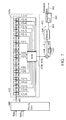
- FIG. 7 is a block diagram of the apparatus for determining an estimated symbol error rate in the receiver in accordance with the second embodiment, which complies with the J83B standard and utilizes the error check equation (14) to estimate the SER.
- a signal stream is received and consecutively demodulated by a QAM demodulator (not shown) into an in-phase symbol stream Sym I and a quadrature symbol stream Sym Q , using 64-QAM demodulation scheme in this embodiment.
- the 7 receiving the in-phase symbol stream Sym I and the quadrature symbol stream Sym Q includes a slicing circuit 400 , a combinational logic unit 410 , an adder 430 , a buffer circuit 440 , a selector 450 and a mapping unit 460 .
- the combinational logic unit 410 includes a delay line circuit 410 a having a plurality of delay elements D connected in series, and a XOR logic gate 410 b having a plurality of inputs respectively coupled to the outputs of a part of the delay elements D of the delay line circuit 410 a .
- the adder 430 , the buffer circuit 440 and the selector 450 constituting the accumulator 30 shown in FIG. 1 generates the parity check error rate 454 .
- the slicing circuit 400 receives the in-phase symbol stream Sym I and the quadrature symbol stream Sym Q and generates a corresponding bit stream 402 , which corresponds to one of the coded bit streams 329 and 339 (U or V) in the transmitter. In the embodiment, only the coded bit stream U is illustrated.
- the bit stream 402 is sent to the combinational logic unit 410 .
- the delay line circuit 410 a stores a finite sequence of the bit stream 402 using a plurality of unit delay elements D connected in series. As depicted in FIG. 7 , the delay line circuit 410 a has 21 unit delay elements to store the sequence from U[n ⁇ 6] to U[n+14] of the bit stream 402 .
- the outputs of the first (Right), second, third, fourth, fifth, sixth, eighth, eleventh, twelfth, fifteenth, sixteenth, eighteenth, nineteenth, twentieth, and twenty-first (Left) unit delay elements and the current bit are connected to the inputs of the XOR logic gate 410 b .
- the XOR logic gate 410 b consecutively performs XOR operation on these inputs to generate an error check bit stream 410 c .
- Each bit in the error check bit stream 410 c represents the result of the error check equation (14).
- Adder 430 sums the error check bit stream 410 c and a feedback number stream 435 from the buffer circuit 440 to output an accumulated number stream N ACC .
- the buffer circuit 440 has 5 buffer elements corresponding to the five possible punctured positions to store and shift the accumulated number stream N ACC , forming the feedback number stream 435 .
- Adder 430 and the buffer circuit 440 can accumulate the results of the XOR operations based on the error check equation (14) for the five possible punctured positions, respectively.
- error check equation (14) in the ideal case, the result of the logic operation XOR should be zero if the corresponding punctured position is correct, and should be one if the corresponding punctured position is incorrect. Accordingly, the accumulated number of the accumulated number stream N ACC corresponding to the correct punctured position remains at or is close to zero while those corresponding to the incorrect punctured positions increase rapidly.
- Selector 450 selects one of the five possible punctured positions based on the accumulated number stream N ACC with a minimal value and generates an indicator 452 indicating a detected punctured position at an instant when predetermined iterations have been performed.
- the detected punctured position indicated by the indicator 452 corresponds to one of the five buffer elements storing a minimal value of the accumulated number stream N ACC .
- the selector 450 based on the selected punctured position, can generate the nominal error-check error number and the nominal error-check error rate 454 can inherently be obtained by dividing the number of current trials (the minimal value stored in the buffer element) over the total number of error check operations.
- the mapping unit 460 converts the nominal error-check rate 454 to an estimated symbol error rate (SER) 462 with respect to the input symbol streams Sym I and Sym Q according to a predetermined relation between the nominal error-check rate and the estimated symbol error rate, which can be determined if the error check equation is known. Similar to the first embodiment, the relation between the NER and the estimated SER can be determined by calculating the bit error rates for various conditions, deducing the relation between these bit error rates with the NER and the estimated SER and finally finding out the relation between the NER and the estimated SER.
- FIG. 8 is a graph showing the relation between the NER and the estimated SER applied in the mapping unit 460 in accordance with the embodiment. In FIG.
- numeral 480 denotes a plot of the curve showing the relation between the NER and the estimated SER.
- the mapping unit 460 can convert the NER 454 to the estimated SER 462 using linear or piece-wise linear or other curve-fitting approximation.
- the apparatus for determining the estimated SER in the receiver complying with the J83B standard can utilize the predetermined error check equation, which is deduced based on the transmitter, to achieve the object of the embodiment.
- the input bit stream relevant to coded bits U is chosen to illustrate the details, which is not used to limit the scope the invention. It is noted that the input bit streams relevant to coded bits U and V can individually or simultaneously achieve the objective of generating an estimated symbol error rate in a receiver. Simultaneous usage of the input bit streams relevant to coded bits U and V can shorten the cycle of iterations for testing but requires more components.
- the claimed invention error-metric detector can be wildly use in all application for estimation symbol error rate or bit error rate.
- DVB standard ETSI EN300 421 V1.1.2 (1997-08), 744 V1.4.1 (2001-01) or ETSI EN 300 468 V1.5.1 can be used as the same.
- the invention can be used in a plurality of applications, which need of error detection function, specially requiring decoding/puncturing application, calculating convolution errors, and other application required to estimate error metric on the receiver side of digital communication.
- the scope of the invention should not be limited thereto.
- the communication system is used to determine burst error in order to feedback the burst error indicator to the demodulator.
- FIG. 9 is a block diagram to illustrate using the apparatus of error-check detector to find accumulated error similarly to prior illustration in the first and second embodiments, but taking those data to a burst error detector to determine the burst error instead of passing those data into the mapping unit as the method for estimating the symbol error rate. Since burst error normally need to be determined within the short period of time unlike estimating symbol error rate normally wait for the longer period of time in order to analyze the data stream, the predetermined time period need to be set in order to promptly detect the burst error. Generally, there is a plurality of method proposed for detecting the burst error.
- the preferred method and embodiment of present invention use a fixed, single-level, multi-level, or adaptively threshold to detect burst error.
- the threshold could also be determined according to previous training or system desired.
- the determination of the burst error is fed back into demodulator to further adjust the error-checking equation.
- FIG. 9 is a block diagram of a digital communication receiver using the error-check detector shown in FIG. 1 to determine the burst error in accordance with the embodiment.
- the digital communication receiver can be a high fidelity digital television set complying to the DVB standard or the like.
- the receiver has a tuner 70 , a demodulator 72 , a FEC (forward error corrector) 74 and a burst error detector 80 .
- the burst error detector 80 includes an error-check detector 82 , which is the same as the one shown in FIG. 1 , and a burst error detection unit 84 .
- Tuner 70 is used to tune a RF digital signal and produces a received symbol stream corresponding to a selected channel by down-converting.
- Demodulator 72 demodulates the received symbol stream using a demodulation scheme associated with the modulation scheme utilized in the transmitter, such as Quadrature Phase Shift Keying (QPSK) and Quadrature Amplitude Modulation (QAM).
- FEC 74 decodes the demodulated symbols into the recovered bits using a convolutional decoder, such as Viterbi decoder.
- burst error detector 80 is used to determine the burst error using the demodulated symbols 600 and produces a burst error indicator 700 to demodulator 72 to further adjust the error-check equation.
- Error-check detector 82 has a decision unit 820 , a combinational logic unit 822 and an accumulator 824 .
- decision unit 820 receives the demodulated symbols 600 and generates at least one input bit stream.
- Combinational logic unit 822 performs a combinational logic operation on delayed and current bits of the input bit stream in accordance with a polynomial error-check equation to generate an error-check bit stream, which represents results of the combinational logic operation.
- accumulator 824 accumulates a number of trials with respect to the error check bit stream and generates a nominal error-check number based on the number of the correct trials.
- the nominal error-check number is fed into burst error detection unit 84 to detect the burst error.
- burst error detection unit 84 using predetermined threshold, verifies the nominal error-check number to detect the burst error and produces the burst error indicator 700 to feed back into the demodulator 72 .
- the error-check detector described in FIG. 1 can also be used to determine the burst error in the communication system.
Abstract
Description
Z 0 [n]=Q 0 [n−1]; (1)
Q 0 [n]=Z 1 [n]⊕Q 1 [n−1]; (2)
Q 1 [n−1]=Z 0 [n−1], (3)
Z 0 [n+1]⊕Z 1 [n]⊕Z 0 [n−1]=0 (4)
SER=1−(1−P e(z 0))×(1−P e(z 1))×(1−P e(z 2)) (10)
OUTU =X[1]⊕X[−1]⊕X[−3]; (12)
OUTL =X[1]⊕X[0]⊕X[−1]⊕X[−2]⊕X[−3] (13)
U[n+1]=X[n+1]⊕X[n]⊕X[n−1]⊕X[n−2]⊕X[n−3];
U[n+2]=X[n+2]⊕X[n+1]⊕X[n]⊕X[n−1]⊕X[n−2];
U[n+3]=X[n+3]⊕X[n+2]⊕X[n+1]⊕X[n]⊕X[n−1];
U[n+4]=X[n+4]⊕X[n+2]⊕X[n];
U[n+5]=X[n+4]⊕X[n+3]⊕X[n+2]⊕X[n+1]⊕X[n];
U[n−9]=X[n−7]⊕X[n−8]⊕X[n−9]⊕X[n−10]⊕X[n−11];
U[n−8]=X[n−6]⊕X[n−7]⊕X[n−8]⊕X[n−9]⊕X[n−10];
U[n−7]=X[n−5]⊕X[n−6]⊕X[n−7]⊕X[n−8]⊕X[n−9];
U[n−6]=X[n−4]⊕X[n−6]⊕X[n−8];
U[n−5]=X[n−4]⊕X[n−5]⊕X[n−6]⊕X[n−7]⊕X[n−8];
U[n−4]=X[n−3]⊕X[n−4]⊕X[n−5]⊕X[−6]⊕X[−7];
U[n−3]=X[n−2]⊕X[n−3]⊕X[n−4]⊕X[n−5]⊕X[n−6];
U[n−2]=X[n−1]⊕X[n−2]⊕X[n−3]⊕X[n−4]⊕X[n−5];
U[n−1]=X[n]⊕X[n−2]⊕X[n−4];
U[n]=X[n]⊕X[n−1]⊕X[n−2]⊕X[n−3]⊕X[n−4];
U[n+6]=X[n+5]⊕X[n+4]⊕X[n+3]⊕X[n+2]⊕X[n+1];
U[n+7]=X[n+6]⊕X[n+5]⊕X[n+4]⊕X[n+3]⊕X[n+2];
U[n+8]=X[n+7]⊕X[n+6]⊕X[n+5]⊕X[n+4]⊕X[n+3];
U[n+9]=X[n+8]⊕X[n+6]⊕X[n+4];
U[n+10]=X[n+8]⊕X[n+7]⊕X[n+6]⊕X[n+5]⊕X[n+4];
U[n+11]=X[n+9]⊕X[n+8]⊕X[n+7]⊕X[n+6]⊕X[n+5];
U[n+12]=X[n+10]⊕X[n+9]⊕X[n+8]⊕X[n+7]⊕X[n+6];
U[n+13]=X[n+11]⊕X[n+10]⊕X[n+9]⊕X[n+8]⊕X[n+7];
U[n+14]=X[n+12]⊕X[n+10]⊕X[n+8];
U[n+15]=X[n+12]⊕X[n+11]⊕X[n+10]⊕X[n+9]⊕X[n+8].
U[n−6]⊕U[n−5]⊕U[n−4]⊕U[n−3]⊕U[n−2]⊕U[n−1]⊕U[n+1]⊕U[n+4]⊕U[n+5]⊕U[n+8]⊕U[n+9]⊕U[n+11]⊕U[n+12]⊕U[n+13]⊕U[n+14]⊕U[n+15]≡0 (14)
Claims (32)
Priority Applications (4)
| Application Number | Priority Date | Filing Date | Title |
|---|---|---|---|
| US11/684,029 US7890847B2 (en) | 2007-03-09 | 2007-03-09 | Apparatus and method for calculating error metrics in a digital communication system |
| TW096124101A TWI341104B (en) | 2007-03-09 | 2007-07-03 | Apparatus and method for calculating error metrics in a digital communication system |
| CN2007101281445A CN101262324B (en) | 2007-03-09 | 2007-07-06 | Apparatus and method for calculating error metrics in a digital communication system |
| US12/206,121 US8286051B2 (en) | 2005-07-15 | 2008-09-08 | Method and apparatus for burst error detection and digital communication device |
Applications Claiming Priority (1)
| Application Number | Priority Date | Filing Date | Title |
|---|---|---|---|
| US11/684,029 US7890847B2 (en) | 2007-03-09 | 2007-03-09 | Apparatus and method for calculating error metrics in a digital communication system |
Related Parent Applications (1)
| Application Number | Title | Priority Date | Filing Date |
|---|---|---|---|
| US11/160,927 Continuation-In-Part US7673222B2 (en) | 2005-07-15 | 2005-07-15 | Error-correcting apparatus including multiple error-correcting modules functioning in parallel and related method |
Related Child Applications (1)
| Application Number | Title | Priority Date | Filing Date |
|---|---|---|---|
| US11/675,664 Continuation-In-Part US7865812B2 (en) | 2005-07-15 | 2007-02-16 | Apparatus and method for determining a detected punctured position in punctured convolutional codes |
Publications (2)
| Publication Number | Publication Date |
|---|---|
| US20080222461A1 US20080222461A1 (en) | 2008-09-11 |
| US7890847B2 true US7890847B2 (en) | 2011-02-15 |
Family
ID=39742859
Family Applications (1)
| Application Number | Title | Priority Date | Filing Date |
|---|---|---|---|
| US11/684,029 Expired - Fee Related US7890847B2 (en) | 2005-07-15 | 2007-03-09 | Apparatus and method for calculating error metrics in a digital communication system |
Country Status (3)
| Country | Link |
|---|---|
| US (1) | US7890847B2 (en) |
| CN (1) | CN101262324B (en) |
| TW (1) | TWI341104B (en) |
Families Citing this family (3)
| Publication number | Priority date | Publication date | Assignee | Title |
|---|---|---|---|---|
| US8555138B2 (en) * | 2011-06-08 | 2013-10-08 | Xg Technology, Inc. | Symbol error detection method |
| US9136952B2 (en) * | 2014-01-17 | 2015-09-15 | Tektronix, Inc. | Pulse amplitude modulation (PAM) bit error test and measurement |
| JP6821719B2 (en) * | 2019-01-23 | 2021-01-27 | アンリツ株式会社 | Burst error addition device, test signal generator using it, and burst error addition method |
Citations (10)
| Publication number | Priority date | Publication date | Assignee | Title |
|---|---|---|---|---|
| US5434886A (en) | 1992-01-24 | 1995-07-18 | Hitachi, Ltd. | Digital communication system |
| US5668820A (en) | 1995-01-23 | 1997-09-16 | Ericsson Inc. | Digital communication system having a punctured convolutional coding system and method |
| US5691992A (en) | 1995-10-12 | 1997-11-25 | Ericsson Inc. | Punctured coding system for providing unequal error protection in a digital communication system |
| US5708665A (en) | 1996-08-22 | 1998-01-13 | Lsi Logic Corporation | Digital receiver using equalization and block decoding with erasure and error correction |
| US5812603A (en) | 1996-08-22 | 1998-09-22 | Lsi Logic Corporation | Digital receiver using a concatenated decoder with error and erasure correction |
| US20030192001A1 (en) | 2002-04-05 | 2003-10-09 | Iit Research Institute | Decoding method and apparatus |
| US6728323B1 (en) | 2000-07-10 | 2004-04-27 | Ericsson Inc. | Baseband processors, mobile terminals, base stations and methods and systems for decoding a punctured coded received signal using estimates of punctured bits |
| US7131055B2 (en) * | 2003-02-25 | 2006-10-31 | Intel Corporation | Fast bit-parallel Viterbi decoder add-compare-select circuit |
| US7478306B2 (en) | 2004-03-31 | 2009-01-13 | Sanyo Electric Co., L:Td. | Method of detecting error location, and error detection circuit, error correction circuit, and reproducing apparatus using the method |
| US20090055717A1 (en) * | 2004-10-27 | 2009-02-26 | Marvell International Ltd. | Architecture and control of reed-solomon list decoding |
Family Cites Families (3)
| Publication number | Priority date | Publication date | Assignee | Title |
|---|---|---|---|---|
| KR0165507B1 (en) * | 1996-01-09 | 1999-03-20 | 김광호 | Equalizing method and equalizer using standard signal |
| JP3288574B2 (en) * | 1996-02-26 | 2002-06-04 | 松下電器産業株式会社 | Data receiving device |
| CN1157854C (en) * | 2000-07-25 | 2004-07-14 | 华为技术有限公司 | High-speed Turbo code decoder |
-
2007
- 2007-03-09 US US11/684,029 patent/US7890847B2/en not_active Expired - Fee Related
- 2007-07-03 TW TW096124101A patent/TWI341104B/en not_active IP Right Cessation
- 2007-07-06 CN CN2007101281445A patent/CN101262324B/en not_active Expired - Fee Related
Patent Citations (10)
| Publication number | Priority date | Publication date | Assignee | Title |
|---|---|---|---|---|
| US5434886A (en) | 1992-01-24 | 1995-07-18 | Hitachi, Ltd. | Digital communication system |
| US5668820A (en) | 1995-01-23 | 1997-09-16 | Ericsson Inc. | Digital communication system having a punctured convolutional coding system and method |
| US5691992A (en) | 1995-10-12 | 1997-11-25 | Ericsson Inc. | Punctured coding system for providing unequal error protection in a digital communication system |
| US5708665A (en) | 1996-08-22 | 1998-01-13 | Lsi Logic Corporation | Digital receiver using equalization and block decoding with erasure and error correction |
| US5812603A (en) | 1996-08-22 | 1998-09-22 | Lsi Logic Corporation | Digital receiver using a concatenated decoder with error and erasure correction |
| US6728323B1 (en) | 2000-07-10 | 2004-04-27 | Ericsson Inc. | Baseband processors, mobile terminals, base stations and methods and systems for decoding a punctured coded received signal using estimates of punctured bits |
| US20030192001A1 (en) | 2002-04-05 | 2003-10-09 | Iit Research Institute | Decoding method and apparatus |
| US7131055B2 (en) * | 2003-02-25 | 2006-10-31 | Intel Corporation | Fast bit-parallel Viterbi decoder add-compare-select circuit |
| US7478306B2 (en) | 2004-03-31 | 2009-01-13 | Sanyo Electric Co., L:Td. | Method of detecting error location, and error detection circuit, error correction circuit, and reproducing apparatus using the method |
| US20090055717A1 (en) * | 2004-10-27 | 2009-02-26 | Marvell International Ltd. | Architecture and control of reed-solomon list decoding |
Non-Patent Citations (1)
| Title |
|---|
| Office Action mailed in related U.S. Appl. No. 11/160,927, dated Apr. 3, 2009. |
Also Published As
| Publication number | Publication date |
|---|---|
| TW200838210A (en) | 2008-09-16 |
| US20080222461A1 (en) | 2008-09-11 |
| CN101262324A (en) | 2008-09-10 |
| CN101262324B (en) | 2010-12-08 |
| TWI341104B (en) | 2011-04-21 |
Similar Documents
| Publication | Publication Date | Title |
|---|---|---|
| US7865812B2 (en) | Apparatus and method for determining a detected punctured position in punctured convolutional codes | |
| US20070248187A1 (en) | Vsb transmission system | |
| US20120297267A1 (en) | Error floor reduction in iteratively decoded fec codes | |
| Liu et al. | Parameter identification of Reed-Solomon codes based on probability statistics and Galois field Fourier transform | |
| US20150237407A1 (en) | Signal receiving apparatus based on faster than nyquist and signal decoding method thereof | |
| CN100527803C (en) | Enhanced VSB viterbi decoder | |
| US8375279B2 (en) | Receiving device and receiving method | |
| US7890847B2 (en) | Apparatus and method for calculating error metrics in a digital communication system | |
| EP2005599B1 (en) | Improved method for decoding digital data in a frequency hopping communication system | |
| US8286051B2 (en) | Method and apparatus for burst error detection and digital communication device | |
| TWI404368B (en) | Digital communication device and decoding method | |
| CN101141229A (en) | Apparatus and method for detecting puncture position | |
| US20030018941A1 (en) | Method and apparatus for demodulation | |
| WO2014023472A1 (en) | Improved blind transport format detection depending on the conditions of reception of the signal | |
| JP2008502246A (en) | Compensation system for turbo decoder phase shift | |
| WO2021084890A1 (en) | Wireless communication system and wireless communication method | |
| EP2406908B1 (en) | Mimo communication method and devices | |
| KR100441510B1 (en) | The appartus for correcting error of data using channel state information | |
| US9118480B2 (en) | Frame quality estimation during viterbi decoding | |
| US6947503B2 (en) | Method and circuit for synchronizing a receiver for a convolutionally coded reception signal | |
| JP4188769B2 (en) | Transmission method and apparatus, reception method and apparatus, and communication system using them | |
| US7844279B2 (en) | Method for measuring radio channel quality and related equipment | |
| WO2019176147A1 (en) | Wireless communication system | |
| US20170257232A1 (en) | Equalizer apparatus and viterbi algorithm based decision method | |
| Sharma et al. | Forward Error Correction (FEC) Coding Techniques for Reliable Communication Systems |
Legal Events
| Date | Code | Title | Description |
|---|---|---|---|
| AS | Assignment |
Owner name: MEDIATEK INC., TAIWAN Free format text: ASSIGNMENT OF ASSIGNORS INTEREST;ASSIGNORS:LIOU, MING-LUEN;CHIOU, RONG-LIANG;REEL/FRAME:018985/0501 Effective date: 20070227 |
|
| FPAY | Fee payment |
Year of fee payment: 4 |
|
| FEPP | Fee payment procedure |
Free format text: MAINTENANCE FEE REMINDER MAILED (ORIGINAL EVENT CODE: REM.); ENTITY STATUS OF PATENT OWNER: LARGE ENTITY |
|
| LAPS | Lapse for failure to pay maintenance fees |
Free format text: PATENT EXPIRED FOR FAILURE TO PAY MAINTENANCE FEES (ORIGINAL EVENT CODE: EXP.); ENTITY STATUS OF PATENT OWNER: LARGE ENTITY |
|
| STCH | Information on status: patent discontinuation |
Free format text: PATENT EXPIRED DUE TO NONPAYMENT OF MAINTENANCE FEES UNDER 37 CFR 1.362 |
|
| FP | Lapsed due to failure to pay maintenance fee |
Effective date: 20190215 |