US7894552B1 - Ultra-efficient hardware-based decimation technique - Google Patents

Ultra-efficient hardware-based decimation technique Download PDF

Info

Publication number
US7894552B1
US7894552B1 US11/879,457 US87945707A US7894552B1 US 7894552 B1 US7894552 B1 US 7894552B1 US 87945707 A US87945707 A US 87945707A US 7894552 B1 US7894552 B1 US 7894552B1
Authority
US
United States
Prior art keywords
signal
quadrature
combiner
phase
component
Prior art date
Legal status (The legal status is an assumption and is not a legal conclusion. Google has not performed a legal analysis and makes no representation as to the accuracy of the status listed.)
Expired - Fee Related, expires
Application number
US11/879,457
Inventor
Joseph T. Graf
Current Assignee (The listed assignees may be inaccurate. Google has not performed a legal analysis and makes no representation or warranty as to the accuracy of the list.)
Rockwell Collins Inc
Original Assignee
Rockwell Collins Inc
Priority date (The priority date is an assumption and is not a legal conclusion. Google has not performed a legal analysis and makes no representation as to the accuracy of the date listed.)
Filing date
Publication date
Application filed by Rockwell Collins Inc filed Critical Rockwell Collins Inc
Priority to US11/879,457 priority Critical patent/US7894552B1/en
Assigned to ROCKWELL COLLINS, INC. reassignment ROCKWELL COLLINS, INC. ASSIGNMENT OF ASSIGNORS INTEREST (SEE DOCUMENT FOR DETAILS). Assignors: GRAF, JOSEPH T.
Application granted granted Critical
Publication of US7894552B1 publication Critical patent/US7894552B1/en
Expired - Fee Related legal-status Critical Current
Adjusted expiration legal-status Critical

Links

Images

Classifications

    • HELECTRICITY
    • H04ELECTRIC COMMUNICATION TECHNIQUE
    • H04BTRANSMISSION
    • H04B1/00Details of transmission systems, not covered by a single one of groups H04B3/00 - H04B13/00; Details of transmission systems not characterised by the medium used for transmission
    • H04B1/0003Software-defined radio [SDR] systems, i.e. systems wherein components typically implemented in hardware, e.g. filters or modulators/demodulators, are implented using software, e.g. by involving an AD or DA conversion stage such that at least part of the signal processing is performed in the digital domain
    • H04B1/0007Software-defined radio [SDR] systems, i.e. systems wherein components typically implemented in hardware, e.g. filters or modulators/demodulators, are implented using software, e.g. by involving an AD or DA conversion stage such that at least part of the signal processing is performed in the digital domain wherein the AD/DA conversion occurs at radiofrequency or intermediate frequency stage
    • H04B1/0025Software-defined radio [SDR] systems, i.e. systems wherein components typically implemented in hardware, e.g. filters or modulators/demodulators, are implented using software, e.g. by involving an AD or DA conversion stage such that at least part of the signal processing is performed in the digital domain wherein the AD/DA conversion occurs at radiofrequency or intermediate frequency stage using a sampling rate lower than twice the highest frequency component of the sampled signal

Definitions

  • the present invention relates generally to signal processing and more particularly to hardware-based decimation.
  • VHSIC very-high-speed integrated circuit hardware description language
  • FPGA field-programmable gate array
  • the first stage of decimation (a technique for reducing the number of samples in a discrete-time signal) is traditionally provided by feeding an oversampled sequence into a CIC (cascaded integrator comb) filter, even this may require more logic than can be spared for a given application.
  • CIC cascaded integrator comb
  • the intermediate frequency (IF) signal is fed into an analog-to-digital converter 101 .
  • the converted signal is separately mixed 104 and 105 with an in-phase component 102 and a quadrature component 103 .
  • the in-phase signal and quadrature signal are then separately filtered 106 and 107 and the sample rate of each is separately reduced 108 and 109 .
  • the mixer sequences simplify to a ⁇ 1, 0, ⁇ 1, 0 ⁇ sequence for the in-phase signal and a ⁇ 0, ⁇ 1, 0, 1 ⁇ or ⁇ 0, 1, 0, ⁇ 1 ⁇ for the quadrature signal.
  • a representation of the quadrature mix is shown in FIG. 2 .
  • the present invention is directed to a quick reduction in sample rate requiring minimal logic.
  • An IF signal is passed into an analog-to-digital converter.
  • the converted signal is mixed with the combination of an in-phase and a quadrature component.
  • the mixed signal is then split into an in-phase signal and a quadrature signal.
  • the quadrature signal is interpolated to form a new signal aligned in time to the in-phase signal.
  • the in-phase signal is interpolated to form a new signal aligned in time to the quadrature signal.
  • the interpolation may comprise linear interpolation.
  • the linear interpolation may be performed by passing the quadrature signal through a sample delay component, combining the delayed signal with the original signal, and shifting the combination to the right by one to effectively divide the result by two.
  • the interpolation may comprise parabolic interpolation.
  • the parabolic interpolation may be performed by passing the quadrature signal through a first sample delay component, passing the delayed signal through a second sample delay component, combining the signal with the result of the second delayed signal and the negative of the result of the first delayed signal to form a first combination, combining the signal with the negative of the result of the second sample delay component to form a second combination, shifting the first and second combinations, and combining the result of the first delayed signal with the first and second shifted combinations.
  • the present invention provides a quick, low-distortion and efficient reduction in sample rates requiring minimal logic.
  • the signal processing simplification reduces the sample rate of the signal and interpolation of either the in-phase signal or quadrature signal reduces aliasing introduced by the simplification.
  • the interpolation may comprise linear interpolation.
  • the interpolation may comprise parabolic interpolation, which greatly reduces aliasing introduced by the simplification with a minimal increase in complexity.
  • One advantage of this approach is that only half of the signal (either the in-phase signal or the quadrature signal) needs to be processed.
  • the present invention results in a “quick” reduction in sample rate with an improvement in quality over the simplification alone with very little combinational logic as compared to the already efficient CIC filters traditionally utilized. Such a simple reduction in sample rate can drastically influence downstream design as it may be challenged by the clock speed of the device, which impacts design and power consumption.
  • FIG. 1 is a block diagram illustrating the traditional breakdown of signal processing within a SDR application, as is known in the art
  • FIG. 2 is a diagram illustrating a representation of the quadrature mix of a traditional breakdown of signal processing within a SDR application, as is known in the art;
  • FIG. 3 is a block diagram illustrating a simplified breakdown of signal processing within a SDR application
  • FIG. 4 is a block diagram illustrating a simplified signal processing within a SDR application utilizing linear interpolation to reduce aliasing, in accordance with an exemplary embodiment of the present invention
  • FIG. 5 is a block diagram illustrating parabolic interpolation for reducing aliasing in a simplified signal processing within a SDR application, in accordance with an alternative embodiment of the present invention
  • FIG. 6 is flow chart illustrating a method of decimation, in accordance with an exemplary embodiment of the present invention.
  • FIG. 7 is block diagram illustrating a system for decimating, in accordance with an exemplary embodiment of the present invention.
  • the quadrature mix of traditional breakdown of signal processing within a SDR application does not include cross products in the complex mix. Since there are no cross products in the complex mix, a simplification can be made.
  • an intermediate frequency (IF) signal is fed into an analog-to-digital converter 301 .
  • the converted signal is mixed 305 with the combination 304 of an in-phase component 302 and a quadrature component 303 .
  • the combination 304 of the in-phase and quadrature components 302 and 303 (effectively) form a real stream ⁇ 1, ⁇ 1, ⁇ 1, 1 ⁇ or ⁇ 1, 1, ⁇ 1, ⁇ 1 ⁇ which is then directly mixed 305 with the real IF signal.
  • This simplification results in the output of the mixer 305 represented by the sequence (I 0 , Q 1 , I 2 , Q 3 ).
  • the zeros are absent from the sequence. This is an important optimization, as the zeros effectively carry no information.
  • the zeros may be reinserted later, if desired.
  • the mixed signal may then be split 306 into an in-phase signal and a quadrature signal, halving the sample rate of the mixed signal.
  • phase error is introduced into the sequence. This error manifests as alias energy because the mix is no longer “perfect.” As the information bandwidth increases relative to the sample rate the amount of aliasing will likewise increase.
  • the resulting phase error goes down.
  • the interpolation may comprise linear interpolation, parabolic interpolation, or any other curve-fit function that provides an interpolated result.
  • the IF signal is passed into an analog-to-digital converter 401 .
  • the converted signal is mixed 405 with the combination 404 of an in-phase 402 and a quadrature component 403 .
  • the mixed signal is then split 406 into an in-phase signal and a quadrature signal.
  • the quadrature signal is interpolated by linear interpolation to form a new signal aligned in time to the in-phase signal.
  • the linear interpolation may be performed by passing the quadrature signal through a sample delay component 407 , combining 408 the delayed signal with the original signal, and shifting 409 the combination to divide the new sample by two.
  • the quadrature signal may be interpolated by parabolic interpolation to form a new signal aligned in time to the in-phase signal rather than by linear interpolation.
  • the parabolic interpolation may be performed by passing the quadrature signal through a first sample delay component 501 , passing the delayed signal through a second sample delay component 502 , combining 503 the signal with the result of the second delayed signal and the negative of the result of the first delayed signal to form a first combination, combining 504 the signal with the negative of the result of the second sample delay component to form a second combination, shifting the first and second combinations 505 and 506 , and combining 507 the result of the first sample delay component with the first and second shifted combinations.
  • the in-phase signal may be interpolated by linear or parabolic interpolation to form a new signal aligned in time to the quadrature signal.
  • a method 600 of decimation in accordance with an exemplary embodiment of the present invention, is shown.
  • a an intermediate frequency signal is passed through an analog-to-digital converter.
  • an in-phase component is combined with a quadrature component.
  • the combination is mixed with the converted signal.
  • the mixed signal is split into an in-phase signal and a quadrature signal.
  • either the in-phase signal or the quadrature signal is interpolated.
  • the system 700 comprises an analog-to-digital converter 701 for converting an IF signal, a combiner 704 for combining an in-phase component 702 with a quadrature component 703 , a mixer 705 for mixing the combination with the converted signal, a splitter 706 for splitting the mixed signal into an in-phase signal and a quadrature signal, and an interpolation unit 707 for interpolating the quadrature signal to form a new signal aligned in time to the in-phase signal.
  • the interpolation unit 707 may perform linear interpolation.
  • the interpolation unit 707 may perform parabolic interpolation. Alternatively, the interpolation unit 707 may interpolate the in-phase signal to form a new signal aligned in time to the quadrature signal.
  • the present invention provides quick, low-distortion and efficient reduction in sample rates requiring minimal logic.
  • the signal processing simplification reduces the sample rate of the signal and interpolation of either the in-phase signal or quadrature signal reduces aliasing introduced by the simplification.
  • the interpolation may comprise linear interpolation.
  • the interpolation may comprise parabolic interpolation, which greatly reduces aliasing introduced by the simplification with a very modest increase in complexity.
  • One advantage of this approach is that only half of the signal (either the in-phase signal or the quadrature signal) needs to be processed.
  • the present invention results in a “quick” reduction in sample rate with an improvement in quality over the simplification alone with very little combinational logic as compared to the already efficient CIC traditionally utilized.

Abstract

The present invention is directed to a quick, low-distortion and efficient reduction in sample rate requiring minimal logic. An IF signal is passed into an analog-to-digital converter. The converted signal is mixed with the combination of an in-phase and a quadrature component. The mixed signal is then split into an in-phase signal and a quadrature signal. The quadrature signal is interpolated to form a new signal aligned in time to the in-phase signal. Alternatively, the in-phase signal is interpolated to form a new signal aligned in time to the quadrature signal. The interpolation may comprise linear interpolation or parabolic interpolation. The simplified signal processing reduces the sample rate of the signal and the interpolation reduces aliasing introduced by the simplification. One advantage of this approach is that only half of the signal needs to be processed.

Description

FIELD OF THE INVENTION
The present invention relates generally to signal processing and more particularly to hardware-based decimation.
BACKGROUND OF THE INVENTION
In many software-defined radio (SDR) applications, such as Tactical Data Radio Systems (TDRS), there are significant portions of the waveform that reside in VHSIC (very-high-speed integrated circuit) hardware description language (VHDL). In many SDR applications, the portions of the waveform that reside in VHDL are implemented utilizing FPGA's (field-programmable gate array). As designs for SDR applications become more FPGA intensive, the capacity of designs may be limited by hardware resources, clock speeds, thermal requirements, etc. When the capacity of the design is limited, it is often critical to get the sample rate down quickly without requiring a lot of excess logic. Although the first stage of decimation (a technique for reducing the number of samples in a discrete-time signal) is traditionally provided by feeding an oversampled sequence into a CIC (cascaded integrator comb) filter, even this may require more logic than can be spared for a given application.
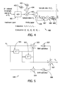
Referring generally to FIG. 1; the traditional breakdown of signal processing within a SDR application, as is known in the art, is illustrated. The intermediate frequency (IF) signal is fed into an analog-to-digital converter 101. The converted signal is separately mixed 104 and 105 with an in-phase component 102 and a quadrature component 103. The in-phase signal and quadrature signal are then separately filtered 106 and 107 and the sample rate of each is separately reduced 108 and 109. When the sample rate is related to the IF signal frequency such that fif is a factor of ¼ or ¾ for fs, the mixer sequences simplify to a {1, 0, −1, 0} sequence for the in-phase signal and a {0, −1, 0, 1} or {0, 1, 0, −1} for the quadrature signal. A representation of the quadrature mix is shown in FIG. 2.
Consequently, it would be desirable to provide a quick, low-distortion and efficient reduction in sample rate requiring minimal logic.
SUMMARY OF THE INVENTION
Accordingly, the present invention is directed to a quick reduction in sample rate requiring minimal logic.
An IF signal is passed into an analog-to-digital converter. The converted signal is mixed with the combination of an in-phase and a quadrature component. The mixed signal is then split into an in-phase signal and a quadrature signal. The quadrature signal is interpolated to form a new signal aligned in time to the in-phase signal. Alternatively, the in-phase signal is interpolated to form a new signal aligned in time to the quadrature signal.
The interpolation may comprise linear interpolation. The linear interpolation may be performed by passing the quadrature signal through a sample delay component, combining the delayed signal with the original signal, and shifting the combination to the right by one to effectively divide the result by two. Alternatively, the interpolation may comprise parabolic interpolation. The parabolic interpolation may be performed by passing the quadrature signal through a first sample delay component, passing the delayed signal through a second sample delay component, combining the signal with the result of the second delayed signal and the negative of the result of the first delayed signal to form a first combination, combining the signal with the negative of the result of the second sample delay component to form a second combination, shifting the first and second combinations, and combining the result of the first delayed signal with the first and second shifted combinations.
The simplification in combining in-phase and quadrature components and directly mixing with the real IF signal results in the absence of zeros from the sequence. This is an important step in optimization, as the zeros effectively carry no information. Although the zeros may not carry any information, they do provide a placeholder to keep the phase information intact. If the zeroes are thrown away (permanently), phase error is introduced into the sequence. This error is manifested as alias energy because the mix is no longer “perfect.” As the information bandwidth increases relative to the sample rate, the amount of aliasing will likewise increase. However, by interpolating adjacent quadrature elements to form a new sample that aligns in time with the non-zero in-phase elements (or interpolating adjacent in-phase elements to form a new sample that aligns in time with the non-zero quadrature elements), the resulting phase error goes down.
The present invention provides a quick, low-distortion and efficient reduction in sample rates requiring minimal logic. The signal processing simplification reduces the sample rate of the signal and interpolation of either the in-phase signal or quadrature signal reduces aliasing introduced by the simplification. The interpolation may comprise linear interpolation. The interpolation may comprise parabolic interpolation, which greatly reduces aliasing introduced by the simplification with a minimal increase in complexity. One advantage of this approach is that only half of the signal (either the in-phase signal or the quadrature signal) needs to be processed. The present invention results in a “quick” reduction in sample rate with an improvement in quality over the simplification alone with very little combinational logic as compared to the already efficient CIC filters traditionally utilized. Such a simple reduction in sample rate can drastically influence downstream design as it may be challenged by the clock speed of the device, which impacts design and power consumption.
It is to be understood that both the foregoing general description and the following detailed description are exemplary and explanatory only and are not restrictive of the invention claimed. The accompanying drawings, which are incorporated in and constitute a part of the specification, illustrate an embodiment of the invention and together with the general description, serve to explain the principles of the invention.
BRIEF DESCRIPTION OF THE DRAWINGS
The numerous objects and advantages of the present invention may be better understood by those skilled in the art by reference to the accompanying figures in which:
FIG. 1 is a block diagram illustrating the traditional breakdown of signal processing within a SDR application, as is known in the art;
FIG. 2 is a diagram illustrating a representation of the quadrature mix of a traditional breakdown of signal processing within a SDR application, as is known in the art;
FIG. 3 is a block diagram illustrating a simplified breakdown of signal processing within a SDR application;
FIG. 4 is a block diagram illustrating a simplified signal processing within a SDR application utilizing linear interpolation to reduce aliasing, in accordance with an exemplary embodiment of the present invention;
FIG. 5 is a block diagram illustrating parabolic interpolation for reducing aliasing in a simplified signal processing within a SDR application, in accordance with an alternative embodiment of the present invention;
FIG. 6 is flow chart illustrating a method of decimation, in accordance with an exemplary embodiment of the present invention.
FIG. 7 is block diagram illustrating a system for decimating, in accordance with an exemplary embodiment of the present invention.
DETAILED DESCRIPTION OF THE INVENTION
Reference will now be made in detail to exemplary embodiments of the invention, examples of which are illustrated in the accompanying drawings.
Referring to FIG. 2, it can be seen that the quadrature mix of traditional breakdown of signal processing within a SDR application does not include cross products in the complex mix. Since there are no cross products in the complex mix, a simplification can be made.
Referring now to FIG. 3, an intermediate frequency (IF) signal is fed into an analog-to-digital converter 301. The converted signal is mixed 305 with the combination 304 of an in-phase component 302 and a quadrature component 303. The combination 304 of the in-phase and quadrature components 302 and 303 (effectively) form a real stream {1, −1, −1, 1} or {1, 1, −1, −1} which is then directly mixed 305 with the real IF signal. This simplification results in the output of the mixer 305 represented by the sequence (I0, Q1, I2, Q3). The zeros are absent from the sequence. This is an important optimization, as the zeros effectively carry no information. The zeros may be reinserted later, if desired. The mixed signal may then be split 306 into an in-phase signal and a quadrature signal, halving the sample rate of the mixed signal.
Although the zeros may not carry any information, they do provide a placeholder to keep the phase information intact. If the zeroes are thrown away (permanently) and that non-zero data grouped as shown in FIG. 3, phase error is introduced into the sequence. This error manifests as alias energy because the mix is no longer “perfect.” As the information bandwidth increases relative to the sample rate the amount of aliasing will likewise increase.
However, if adjacent Q elements are “interpolated” to form a new sample that aligns in time with the non-zero I elements (or adjacent I elements are “interpolated to form a new sample that aligns in time with the non-zero Q elements), the resulting phase error goes down. The interpolation may comprise linear interpolation, parabolic interpolation, or any other curve-fit function that provides an interpolated result.
Referring now to FIG. 4, a breakdown of signal processing, in accordance with an exemplary embodiment of the present invention, is illustrated. The IF signal is passed into an analog-to-digital converter 401. The converted signal is mixed 405 with the combination 404 of an in-phase 402 and a quadrature component 403. The mixed signal is then split 406 into an in-phase signal and a quadrature signal. The quadrature signal is interpolated by linear interpolation to form a new signal aligned in time to the in-phase signal. The linear interpolation may be performed by passing the quadrature signal through a sample delay component 407, combining 408 the delayed signal with the original signal, and shifting 409 the combination to divide the new sample by two.
Referring now to FIG. 5, in an alternative embodiment of the present invention, the quadrature signal may be interpolated by parabolic interpolation to form a new signal aligned in time to the in-phase signal rather than by linear interpolation. The parabolic interpolation may be performed by passing the quadrature signal through a first sample delay component 501, passing the delayed signal through a second sample delay component 502, combining 503 the signal with the result of the second delayed signal and the negative of the result of the first delayed signal to form a first combination, combining 504 the signal with the negative of the result of the second sample delay component to form a second combination, shifting the first and second combinations 505 and 506, and combining 507 the result of the first sample delay component with the first and second shifted combinations.
Alternatively, the in-phase signal may be interpolated by linear or parabolic interpolation to form a new signal aligned in time to the quadrature signal.
Referring now to FIG. 6, a method 600 of decimation, in accordance with an exemplary embodiment of the present invention, is shown. In step 601, a an intermediate frequency signal is passed through an analog-to-digital converter. In step 602, an in-phase component is combined with a quadrature component. In step 603, the combination is mixed with the converted signal. In step 604, the mixed signal is split into an in-phase signal and a quadrature signal. In step 605, either the in-phase signal or the quadrature signal is interpolated.
Referring now to FIG. 7, a system 700 for decimating, in accordance with an exemplary embodiment of the present invention, is illustrated. The system 700 comprises an analog-to-digital converter 701 for converting an IF signal, a combiner 704 for combining an in-phase component 702 with a quadrature component 703, a mixer 705 for mixing the combination with the converted signal, a splitter 706 for splitting the mixed signal into an in-phase signal and a quadrature signal, and an interpolation unit 707 for interpolating the quadrature signal to form a new signal aligned in time to the in-phase signal. The interpolation unit 707 may perform linear interpolation. The interpolation unit 707 may perform parabolic interpolation. Alternatively, the interpolation unit 707 may interpolate the in-phase signal to form a new signal aligned in time to the quadrature signal.
The present invention provides quick, low-distortion and efficient reduction in sample rates requiring minimal logic. The signal processing simplification reduces the sample rate of the signal and interpolation of either the in-phase signal or quadrature signal reduces aliasing introduced by the simplification. The interpolation may comprise linear interpolation. The interpolation may comprise parabolic interpolation, which greatly reduces aliasing introduced by the simplification with a very modest increase in complexity. One advantage of this approach is that only half of the signal (either the in-phase signal or the quadrature signal) needs to be processed. The present invention results in a “quick” reduction in sample rate with an improvement in quality over the simplification alone with very little combinational logic as compared to the already efficient CIC traditionally utilized.
It is understood that the specific order or hierarchy of steps in the processes disclosed is an example of exemplary approaches. Based upon design preferences, it is understood that the specific order or hierarchy of steps in the processes may be rearranged while remaining within the scope of the present invention. The accompanying method claims present elements of the various steps in a sample order, and are not meant to be limited to the specific order or hierarchy presented.
It is believed that the present invention and many of its attendant advantages will be understood by the foregoing description, and it will be apparent that various changes may be made in the form, construction, and arrangement of the components thereof without departing from the scope and spirit of the invention or without sacrificing all of its material advantages. The form herein before described being merely an explanatory embodiment thereof, it is the intention of the following claims to encompass and include such changes.

Claims (4)

1. A software defined radio, comprising:
an analog-to-digital converter for receiving an intermediate frequency signal;
a mixer operatively coupled to the analog-to-digital converter;
a combiner operatively coupled to the mixer;
an in-phase component generator and a quadrature component generator operatively coupled to the combiner;
a splitter operatively coupled to the mixer with an in-phase signal output and a quadrature signal output; and
an interpolation unit operatively coupled to one selected from the in-phase signal output of the splitter and the quadrature signal output of the splitter;
wherein the analog-to-digital converter converts the intermediate frequency signal, the combiner combines the in-phase component and the quadrature component, the mixer mixes the converted signal and the combination, the splitter splits the mixed signal into an in-phase signal and a quadrature signal, and the interpolation unit interpolates one selected from the in-phase signal and the quadrature signal,
wherein the interpolation unit comprises a parabolic interpolation unit, and wherein the parabolic interpolation unit comprises:
a first sample delay component for receiving one selected from the in-phase signal and the quadrature signal;
a second combiner for receiving the one selected from the in-phase signal and the quadrature signal, operatively coupled to the first sample delay component;
a third combiner for receiving the one selected from the in-phase signal and the quadrature signal;
a second sample delay component operatively coupled to the first sample delay component, the second combiner, and the third combiner;
a first shift unit operatively coupled to the second combiner;
a second shift unit operatively coupled to the third combiner; and
a fourth combiner operatively coupled to the first shift unit and the second shift unit;
wherein the first sample delay component delays the one selected from the in-phase signal and the quadrature signal by one sample, the second combiner combines the one selected from the in-phase signal and the quadrature signal with the negative of the delayed signal of the first sample delay component and the delayed signal of the second sample delay component, the third combiner combines the one selected from the in-phase signal and the quadrature signal with the negative of the delayed signal of the second sample delay component, the first shift unit shifts the combination of the second combiner, the second shift unit shifts the combination of the third combiner, and the third combination unit combines the delayed signal of the first sample delay component with the shift of the first shift unit and the shift of the second shift unit.
2. A method of decimation, comprising steps of:
passing an intermediate frequency signal through an analog-to-digital converter;
combining an in-phase component with a quadrature component;
mixing the combination with the converted signal;
splitting the mixed signal into an in-phase signal and a quadrature signal; and
interpolating one selected from the in-phase signal and the quadrature signal,
wherein the step of interpolating comprises parabolic interpolation, and
wherein the step of interpolating comprises:
passing the one selected from the in-phase signal and the quadrature signal through a first sample delay;
passing the first delayed signal through a second sample delay;
combining the one selected from the in-phase signal and the quadrature signal with the negative of the first delayed signal and the second delayed signal to obtain a first combination;
combining the one selected from the in-phase signal and the quadrature signal with the negative of the second delayed signal to obtain a second combination;
shifting the first combination;
shifting the second combination;
combining the shifted first combination with the shifted second combination and the first delayed signal.
3. A system for decimating, comprising:
an analog-to-digital converter for receiving an intermediate frequency signal;
a mixer;
a combiner;
an in-phase component generator;
a quadrature component generator;
a splitter with an in-phase signal output and a quadrature signal output; and
an interpolation unit;
wherein the analog-to-digital converter converts the intermediate frequency signal, the combiner combines the in-phase component and the quadrature component, the mixer mixes the converted signal and the combination of the in-phase component and the quadrature component, the splitter splits the mixed signal into an in-phase signal and a quadrature signal, and the interpolation unit interpolates one selected from the in-phase signal and the quadrature signal,
wherein the interpolation unit comprises a parabolic interpolation unit, and
wherein the parabolic interpolation unit comprises:
a first sample delay component for receiving one selected from the in-phase signal and the quadrature signal;
a second combiner for receiving the one selected from the in-phase signal and the quadrature signal;
a third combiner for receiving the one selected from the in-phase signal and the quadrature signal;
a second sample delay component;
a first shift unit;
a second shift unit; and
a fourth combiner;
wherein the first sample delay component delays the one selected from the in-phase signal and the quadrature signal, the second combiner combines the one selected from the in-phase signal and the quadrature signal with the negative of the delayed signal of the first sample delay component and the delayed signal of the second sample delay component, the third combiner combines the one selected from the in-phase signal and the quadrature signal the signal with the negative of the delayed signal of the second sample delay component, the first shift unit shifts the combination of the second combiner, the second shift unit shifts the combination of the third combiner, and the third combination unit combines the delayed signal of the first sample delay component with the shift of the first shift unit and the shift of the second shift unit.
4. A decimation device, comprising:
an analog-to-digital converter for receiving an intermediate frequency signal;
a mixer operatively coupled to the analog-to-digital converter;
a combiner operatively coupled to the mixer;
an in-phase component generator and a quadrature component generator operatively coupled to the combiner;
a splitter operatively coupled to the mixer with an in-phase signal output and a quadrature signal output; and
an interpolation unit operatively coupled to one selected from the in-phase signal output of the splitter and the quadrature signal output of the splitter;
wherein the analog-to-digital converter converts the intermediate frequency signal, the combiner combines the in-phase component and the quadrature component, the mixer mixes the converted signal and the combination, the splitter splits the mixed signal into an in-phase signal and a quadrature signal, and the interpolation unit interpolates one selected from the in-phase signal and the quadrature signal,
wherein the interpolation unit comprises a parabolic interpolation unit, and
wherein the parabolic interpolation unit comprises:
a first sample delay component for receiving one selected from the in-phase signal and the quadrature signal;
a second combiner for receiving the one selected from the in-phase signal and the quadrature signal, operatively coupled to the first sample delay component;
a third combiner for receiving the one selected from the in-phase signal and the quadrature signal;
a second sample delay component operatively coupled to the first sample delay component, the second combiner, and the third combiner;
a first shift unit operatively coupled to the second combiner;
a second shift unit operatively coupled to the third combiner; and
a fourth combiner operatively coupled to the first shift unit and the second shift unit;
wherein the first sample delay component transforms the one selected from the in-phase signal and the quadrature signal, the second combiner combines the one selected from the in-phase signal and the quadrature signal with the negative of the delayed signal of the first sample delay component and the delayed signal of the second sample delay component, the third combiner combines the signal with the negative of the delayed signal of the second sample delay component, the first shift unit shifts the combination of the second combiner, the second shift unit shifts the combination of the third combiner, and the third combination unit combines the delayed signal of the first sample delay component with the shift of the first shift unit and the shift of the second shift unit.
US11/879,457 2007-07-16 2007-07-16 Ultra-efficient hardware-based decimation technique Expired - Fee Related US7894552B1 (en)

Priority Applications (1)

Application Number Priority Date Filing Date Title
US11/879,457 US7894552B1 (en) 2007-07-16 2007-07-16 Ultra-efficient hardware-based decimation technique

Applications Claiming Priority (1)

Application Number Priority Date Filing Date Title
US11/879,457 US7894552B1 (en) 2007-07-16 2007-07-16 Ultra-efficient hardware-based decimation technique

Publications (1)

Publication Number Publication Date
US7894552B1 true US7894552B1 (en) 2011-02-22

Family

ID=43597143

Family Applications (1)

Application Number Title Priority Date Filing Date
US11/879,457 Expired - Fee Related US7894552B1 (en) 2007-07-16 2007-07-16 Ultra-efficient hardware-based decimation technique

Country Status (1)

Country Link
US (1) US7894552B1 (en)

Citations (6)

* Cited by examiner, † Cited by third party
Publication number Priority date Publication date Assignee Title
US5878088A (en) * 1997-04-10 1999-03-02 Thomson Consumer Electronics, Inc. Digital variable symbol timing recovery system for QAM
US6003055A (en) * 1996-06-03 1999-12-14 Nec Corporation Digital filter interpolation circuit
US6501410B1 (en) * 1999-11-19 2002-12-31 Anritsu Corporation Signal analyzing apparatus
US20030142760A1 (en) * 2002-01-29 2003-07-31 Samsung Electronics Co., Ltd. Carrier recovery apparatus of VSB receiver and a method of recovering carrier using the same
US7010059B2 (en) * 2002-10-07 2006-03-07 Electronics And Telecommunications Research Institute Quadrature demodulator for compensating for gain and phase imbalances between in-phase and quadrature-phase components
US20060269018A1 (en) * 2005-05-27 2006-11-30 Guogang Li Method for timing detection

Patent Citations (6)

* Cited by examiner, † Cited by third party
Publication number Priority date Publication date Assignee Title
US6003055A (en) * 1996-06-03 1999-12-14 Nec Corporation Digital filter interpolation circuit
US5878088A (en) * 1997-04-10 1999-03-02 Thomson Consumer Electronics, Inc. Digital variable symbol timing recovery system for QAM
US6501410B1 (en) * 1999-11-19 2002-12-31 Anritsu Corporation Signal analyzing apparatus
US20030142760A1 (en) * 2002-01-29 2003-07-31 Samsung Electronics Co., Ltd. Carrier recovery apparatus of VSB receiver and a method of recovering carrier using the same
US7010059B2 (en) * 2002-10-07 2006-03-07 Electronics And Telecommunications Research Institute Quadrature demodulator for compensating for gain and phase imbalances between in-phase and quadrature-phase components
US20060269018A1 (en) * 2005-05-27 2006-11-30 Guogang Li Method for timing detection

Similar Documents

Publication Publication Date Title
US5729225A (en) Method and apparatus for asynchronous digital mixing
US20040066803A1 (en) Method and apparatus for shared processing a plurality of signals
EP1262019B1 (en) Apparatus for splitting the frequency band of an input signal
Cordeiro et al. Gigasample time-interleaved delta-sigma modulator for FPGA-based all-digital transmitters
Huang et al. Sample rate conversion using B-spline interpolation for OFDM based software defined radios
CA2457338A1 (en) Digital down converter
US7623833B2 (en) Dual output digital exciter
US7403066B2 (en) Method and system for creating a spectral null in a switching amplifier
TW200807887A (en) Method for converting an ananalog signal to multiple different outputs with an analog-to-digital converter
US7864080B1 (en) Sample rate conversion by controlled selection of filter outputs
US5461612A (en) Drop-and-add multiplexer for converting and processing a frequency multiplex signal
US7894552B1 (en) Ultra-efficient hardware-based decimation technique
US7340024B1 (en) Parallel fractional interpolator with data-rate clock synchronization
US7656332B2 (en) Method and apparatus for a multi-mode multi-rate telemetry transmitter
US20040217891A1 (en) Analog reconstruction of a digital signal
US8188803B2 (en) Apparatus and method for digital up converting in a mobile communication system
EP1388942A2 (en) Conversion circuit, tuner and demodulator
US20080068512A1 (en) Digital radio frequency (rf) modulator
US6501406B1 (en) Digital filter
Harris et al. Multi-resolution PR NMDFBs for programmable variable bandwidth filter in wideband digital transceivers
JP2010130185A (en) Sampling rate conversion circuit
US8295388B1 (en) Efficient digital upconverter
US7853419B2 (en) Signal processing circuit and method for processing an HF input signal
WO2022234766A1 (en) Signal generator and discretionary waveform generation method
KR101740713B1 (en) SDR receiver for radar testing

Legal Events

Date Code Title Description
STCF Information on status: patent grant

Free format text: PATENTED CASE

FPAY Fee payment

Year of fee payment: 4

MAFP Maintenance fee payment

Free format text: PAYMENT OF MAINTENANCE FEE, 8TH YEAR, LARGE ENTITY (ORIGINAL EVENT CODE: M1552); ENTITY STATUS OF PATENT OWNER: LARGE ENTITY

Year of fee payment: 8

FEPP Fee payment procedure

Free format text: MAINTENANCE FEE REMINDER MAILED (ORIGINAL EVENT CODE: REM.); ENTITY STATUS OF PATENT OWNER: LARGE ENTITY

LAPS Lapse for failure to pay maintenance fees

Free format text: PATENT EXPIRED FOR FAILURE TO PAY MAINTENANCE FEES (ORIGINAL EVENT CODE: EXP.); ENTITY STATUS OF PATENT OWNER: LARGE ENTITY

STCH Information on status: patent discontinuation

Free format text: PATENT EXPIRED DUE TO NONPAYMENT OF MAINTENANCE FEES UNDER 37 CFR 1.362

FP Lapsed due to failure to pay maintenance fee

Effective date: 20230222