US7900444B1 - Systems and methods for energy storage and recovery using compressed gas - Google Patents
Systems and methods for energy storage and recovery using compressed gas Download PDFInfo
- Publication number
- US7900444B1 US7900444B1 US12/945,398 US94539810A US7900444B1 US 7900444 B1 US7900444 B1 US 7900444B1 US 94539810 A US94539810 A US 94539810A US 7900444 B1 US7900444 B1 US 7900444B1
- Authority
- US
- United States
- Prior art keywords
- accumulator
- fluid
- intensifier
- pressure
- cylinder assembly
- Prior art date
- Legal status (The legal status is an assumption and is not a legal conclusion. Google has not performed a legal analysis and makes no representation as to the accuracy of the status listed.)
- Expired - Fee Related
Links
Images


Classifications
-
- F—MECHANICAL ENGINEERING; LIGHTING; HEATING; WEAPONS; BLASTING
- F15—FLUID-PRESSURE ACTUATORS; HYDRAULICS OR PNEUMATICS IN GENERAL
- F15B—SYSTEMS ACTING BY MEANS OF FLUIDS IN GENERAL; FLUID-PRESSURE ACTUATORS, e.g. SERVOMOTORS; DETAILS OF FLUID-PRESSURE SYSTEMS, NOT OTHERWISE PROVIDED FOR
- F15B1/00—Installations or systems with accumulators; Supply reservoir or sump assemblies
- F15B1/02—Installations or systems with accumulators
- F15B1/024—Installations or systems with accumulators used as a supplementary power source, e.g. to store energy in idle periods to balance pump load
-
- F—MECHANICAL ENGINEERING; LIGHTING; HEATING; WEAPONS; BLASTING
- F15—FLUID-PRESSURE ACTUATORS; HYDRAULICS OR PNEUMATICS IN GENERAL
- F15B—SYSTEMS ACTING BY MEANS OF FLUIDS IN GENERAL; FLUID-PRESSURE ACTUATORS, e.g. SERVOMOTORS; DETAILS OF FLUID-PRESSURE SYSTEMS, NOT OTHERWISE PROVIDED FOR
- F15B11/00—Servomotor systems without provision for follow-up action; Circuits therefor
- F15B11/02—Systems essentially incorporating special features for controlling the speed or actuating force of an output member
- F15B11/028—Systems essentially incorporating special features for controlling the speed or actuating force of an output member for controlling the actuating force
- F15B11/032—Systems essentially incorporating special features for controlling the speed or actuating force of an output member for controlling the actuating force by means of fluid-pressure converters
-
- F—MECHANICAL ENGINEERING; LIGHTING; HEATING; WEAPONS; BLASTING
- F15—FLUID-PRESSURE ACTUATORS; HYDRAULICS OR PNEUMATICS IN GENERAL
- F15B—SYSTEMS ACTING BY MEANS OF FLUIDS IN GENERAL; FLUID-PRESSURE ACTUATORS, e.g. SERVOMOTORS; DETAILS OF FLUID-PRESSURE SYSTEMS, NOT OTHERWISE PROVIDED FOR
- F15B21/00—Common features of fluid actuator systems; Fluid-pressure actuator systems or details thereof, not covered by any other group of this subclass
- F15B21/08—Servomotor systems incorporating electrically operated control means
-
- F—MECHANICAL ENGINEERING; LIGHTING; HEATING; WEAPONS; BLASTING
- F15—FLUID-PRESSURE ACTUATORS; HYDRAULICS OR PNEUMATICS IN GENERAL
- F15B—SYSTEMS ACTING BY MEANS OF FLUIDS IN GENERAL; FLUID-PRESSURE ACTUATORS, e.g. SERVOMOTORS; DETAILS OF FLUID-PRESSURE SYSTEMS, NOT OTHERWISE PROVIDED FOR
- F15B2211/00—Circuits for servomotor systems
- F15B2211/20—Fluid pressure source, e.g. accumulator or variable axial piston pump
- F15B2211/205—Systems with pumps
- F15B2211/2053—Type of pump
- F15B2211/20569—Type of pump capable of working as pump and motor
-
- F—MECHANICAL ENGINEERING; LIGHTING; HEATING; WEAPONS; BLASTING
- F15—FLUID-PRESSURE ACTUATORS; HYDRAULICS OR PNEUMATICS IN GENERAL
- F15B—SYSTEMS ACTING BY MEANS OF FLUIDS IN GENERAL; FLUID-PRESSURE ACTUATORS, e.g. SERVOMOTORS; DETAILS OF FLUID-PRESSURE SYSTEMS, NOT OTHERWISE PROVIDED FOR
- F15B2211/00—Circuits for servomotor systems
- F15B2211/20—Fluid pressure source, e.g. accumulator or variable axial piston pump
- F15B2211/21—Systems with pressure sources other than pumps, e.g. with a pyrotechnical charge
- F15B2211/212—Systems with pressure sources other than pumps, e.g. with a pyrotechnical charge the pressure sources being accumulators
-
- F—MECHANICAL ENGINEERING; LIGHTING; HEATING; WEAPONS; BLASTING
- F15—FLUID-PRESSURE ACTUATORS; HYDRAULICS OR PNEUMATICS IN GENERAL
- F15B—SYSTEMS ACTING BY MEANS OF FLUIDS IN GENERAL; FLUID-PRESSURE ACTUATORS, e.g. SERVOMOTORS; DETAILS OF FLUID-PRESSURE SYSTEMS, NOT OTHERWISE PROVIDED FOR
- F15B2211/00—Circuits for servomotor systems
- F15B2211/20—Fluid pressure source, e.g. accumulator or variable axial piston pump
- F15B2211/21—Systems with pressure sources other than pumps, e.g. with a pyrotechnical charge
- F15B2211/214—Systems with pressure sources other than pumps, e.g. with a pyrotechnical charge the pressure sources being hydrotransformers
-
- F—MECHANICAL ENGINEERING; LIGHTING; HEATING; WEAPONS; BLASTING
- F15—FLUID-PRESSURE ACTUATORS; HYDRAULICS OR PNEUMATICS IN GENERAL
- F15B—SYSTEMS ACTING BY MEANS OF FLUIDS IN GENERAL; FLUID-PRESSURE ACTUATORS, e.g. SERVOMOTORS; DETAILS OF FLUID-PRESSURE SYSTEMS, NOT OTHERWISE PROVIDED FOR
- F15B2211/00—Circuits for servomotor systems
- F15B2211/20—Fluid pressure source, e.g. accumulator or variable axial piston pump
- F15B2211/21—Systems with pressure sources other than pumps, e.g. with a pyrotechnical charge
- F15B2211/216—Systems with pressure sources other than pumps, e.g. with a pyrotechnical charge the pressure sources being pneumatic-to-hydraulic converters
-
- F—MECHANICAL ENGINEERING; LIGHTING; HEATING; WEAPONS; BLASTING
- F15—FLUID-PRESSURE ACTUATORS; HYDRAULICS OR PNEUMATICS IN GENERAL
- F15B—SYSTEMS ACTING BY MEANS OF FLUIDS IN GENERAL; FLUID-PRESSURE ACTUATORS, e.g. SERVOMOTORS; DETAILS OF FLUID-PRESSURE SYSTEMS, NOT OTHERWISE PROVIDED FOR
- F15B2211/00—Circuits for servomotor systems
- F15B2211/30—Directional control
- F15B2211/305—Directional control characterised by the type of valves
- F15B2211/30505—Non-return valves, i.e. check valves
-
- F—MECHANICAL ENGINEERING; LIGHTING; HEATING; WEAPONS; BLASTING
- F15—FLUID-PRESSURE ACTUATORS; HYDRAULICS OR PNEUMATICS IN GENERAL
- F15B—SYSTEMS ACTING BY MEANS OF FLUIDS IN GENERAL; FLUID-PRESSURE ACTUATORS, e.g. SERVOMOTORS; DETAILS OF FLUID-PRESSURE SYSTEMS, NOT OTHERWISE PROVIDED FOR
- F15B2211/00—Circuits for servomotor systems
- F15B2211/30—Directional control
- F15B2211/305—Directional control characterised by the type of valves
- F15B2211/3056—Assemblies of multiple valves
- F15B2211/30565—Assemblies of multiple valves having multiple valves for a single output member, e.g. for creating higher valve function by use of multiple valves like two 2/2-valves replacing a 5/3-valve
- F15B2211/3057—Assemblies of multiple valves having multiple valves for a single output member, e.g. for creating higher valve function by use of multiple valves like two 2/2-valves replacing a 5/3-valve having two valves, one for each port of a double-acting output member
-
- F—MECHANICAL ENGINEERING; LIGHTING; HEATING; WEAPONS; BLASTING
- F15—FLUID-PRESSURE ACTUATORS; HYDRAULICS OR PNEUMATICS IN GENERAL
- F15B—SYSTEMS ACTING BY MEANS OF FLUIDS IN GENERAL; FLUID-PRESSURE ACTUATORS, e.g. SERVOMOTORS; DETAILS OF FLUID-PRESSURE SYSTEMS, NOT OTHERWISE PROVIDED FOR
- F15B2211/00—Circuits for servomotor systems
- F15B2211/30—Directional control
- F15B2211/305—Directional control characterised by the type of valves
- F15B2211/3056—Assemblies of multiple valves
- F15B2211/30565—Assemblies of multiple valves having multiple valves for a single output member, e.g. for creating higher valve function by use of multiple valves like two 2/2-valves replacing a 5/3-valve
- F15B2211/30575—Assemblies of multiple valves having multiple valves for a single output member, e.g. for creating higher valve function by use of multiple valves like two 2/2-valves replacing a 5/3-valve in a Wheatstone Bridge arrangement (also half bridges)
-
- F—MECHANICAL ENGINEERING; LIGHTING; HEATING; WEAPONS; BLASTING
- F15—FLUID-PRESSURE ACTUATORS; HYDRAULICS OR PNEUMATICS IN GENERAL
- F15B—SYSTEMS ACTING BY MEANS OF FLUIDS IN GENERAL; FLUID-PRESSURE ACTUATORS, e.g. SERVOMOTORS; DETAILS OF FLUID-PRESSURE SYSTEMS, NOT OTHERWISE PROVIDED FOR
- F15B2211/00—Circuits for servomotor systems
- F15B2211/30—Directional control
- F15B2211/305—Directional control characterised by the type of valves
- F15B2211/3056—Assemblies of multiple valves
- F15B2211/30565—Assemblies of multiple valves having multiple valves for a single output member, e.g. for creating higher valve function by use of multiple valves like two 2/2-valves replacing a 5/3-valve
- F15B2211/3058—Assemblies of multiple valves having multiple valves for a single output member, e.g. for creating higher valve function by use of multiple valves like two 2/2-valves replacing a 5/3-valve having additional valves for interconnecting the fluid chambers of a double-acting actuator, e.g. for regeneration mode or for floating mode
-
- F—MECHANICAL ENGINEERING; LIGHTING; HEATING; WEAPONS; BLASTING
- F15—FLUID-PRESSURE ACTUATORS; HYDRAULICS OR PNEUMATICS IN GENERAL
- F15B—SYSTEMS ACTING BY MEANS OF FLUIDS IN GENERAL; FLUID-PRESSURE ACTUATORS, e.g. SERVOMOTORS; DETAILS OF FLUID-PRESSURE SYSTEMS, NOT OTHERWISE PROVIDED FOR
- F15B2211/00—Circuits for servomotor systems
- F15B2211/30—Directional control
- F15B2211/31—Directional control characterised by the positions of the valve element
- F15B2211/3105—Neutral or centre positions
- F15B2211/3111—Neutral or centre positions the pump port being closed in the centre position, e.g. so-called closed centre
-
- F—MECHANICAL ENGINEERING; LIGHTING; HEATING; WEAPONS; BLASTING
- F15—FLUID-PRESSURE ACTUATORS; HYDRAULICS OR PNEUMATICS IN GENERAL
- F15B—SYSTEMS ACTING BY MEANS OF FLUIDS IN GENERAL; FLUID-PRESSURE ACTUATORS, e.g. SERVOMOTORS; DETAILS OF FLUID-PRESSURE SYSTEMS, NOT OTHERWISE PROVIDED FOR
- F15B2211/00—Circuits for servomotor systems
- F15B2211/30—Directional control
- F15B2211/315—Directional control characterised by the connections of the valve or valves in the circuit
- F15B2211/3157—Directional control characterised by the connections of the valve or valves in the circuit being connected to a pressure source, an output member and a return line
- F15B2211/31594—Directional control characterised by the connections of the valve or valves in the circuit being connected to a pressure source, an output member and a return line having multiple pressure sources and multiple output members
-
- F—MECHANICAL ENGINEERING; LIGHTING; HEATING; WEAPONS; BLASTING
- F15—FLUID-PRESSURE ACTUATORS; HYDRAULICS OR PNEUMATICS IN GENERAL
- F15B—SYSTEMS ACTING BY MEANS OF FLUIDS IN GENERAL; FLUID-PRESSURE ACTUATORS, e.g. SERVOMOTORS; DETAILS OF FLUID-PRESSURE SYSTEMS, NOT OTHERWISE PROVIDED FOR
- F15B2211/00—Circuits for servomotor systems
- F15B2211/30—Directional control
- F15B2211/32—Directional control characterised by the type of actuation
- F15B2211/327—Directional control characterised by the type of actuation electrically or electronically
-
- F—MECHANICAL ENGINEERING; LIGHTING; HEATING; WEAPONS; BLASTING
- F15—FLUID-PRESSURE ACTUATORS; HYDRAULICS OR PNEUMATICS IN GENERAL
- F15B—SYSTEMS ACTING BY MEANS OF FLUIDS IN GENERAL; FLUID-PRESSURE ACTUATORS, e.g. SERVOMOTORS; DETAILS OF FLUID-PRESSURE SYSTEMS, NOT OTHERWISE PROVIDED FOR
- F15B2211/00—Circuits for servomotor systems
- F15B2211/40—Flow control
- F15B2211/405—Flow control characterised by the type of flow control means or valve
- F15B2211/40515—Flow control characterised by the type of flow control means or valve with variable throttles or orifices
-
- F—MECHANICAL ENGINEERING; LIGHTING; HEATING; WEAPONS; BLASTING
- F15—FLUID-PRESSURE ACTUATORS; HYDRAULICS OR PNEUMATICS IN GENERAL
- F15B—SYSTEMS ACTING BY MEANS OF FLUIDS IN GENERAL; FLUID-PRESSURE ACTUATORS, e.g. SERVOMOTORS; DETAILS OF FLUID-PRESSURE SYSTEMS, NOT OTHERWISE PROVIDED FOR
- F15B2211/00—Circuits for servomotor systems
- F15B2211/40—Flow control
- F15B2211/415—Flow control characterised by the connections of the flow control means in the circuit
- F15B2211/41509—Flow control characterised by the connections of the flow control means in the circuit being connected to a pressure source and a directional control valve
-
- F—MECHANICAL ENGINEERING; LIGHTING; HEATING; WEAPONS; BLASTING
- F15—FLUID-PRESSURE ACTUATORS; HYDRAULICS OR PNEUMATICS IN GENERAL
- F15B—SYSTEMS ACTING BY MEANS OF FLUIDS IN GENERAL; FLUID-PRESSURE ACTUATORS, e.g. SERVOMOTORS; DETAILS OF FLUID-PRESSURE SYSTEMS, NOT OTHERWISE PROVIDED FOR
- F15B2211/00—Circuits for servomotor systems
- F15B2211/40—Flow control
- F15B2211/415—Flow control characterised by the connections of the flow control means in the circuit
- F15B2211/41554—Flow control characterised by the connections of the flow control means in the circuit being connected to a return line and a directional control valve
-
- F—MECHANICAL ENGINEERING; LIGHTING; HEATING; WEAPONS; BLASTING
- F15—FLUID-PRESSURE ACTUATORS; HYDRAULICS OR PNEUMATICS IN GENERAL
- F15B—SYSTEMS ACTING BY MEANS OF FLUIDS IN GENERAL; FLUID-PRESSURE ACTUATORS, e.g. SERVOMOTORS; DETAILS OF FLUID-PRESSURE SYSTEMS, NOT OTHERWISE PROVIDED FOR
- F15B2211/00—Circuits for servomotor systems
- F15B2211/40—Flow control
- F15B2211/42—Flow control characterised by the type of actuation
- F15B2211/426—Flow control characterised by the type of actuation electrically or electronically
-
- F—MECHANICAL ENGINEERING; LIGHTING; HEATING; WEAPONS; BLASTING
- F15—FLUID-PRESSURE ACTUATORS; HYDRAULICS OR PNEUMATICS IN GENERAL
- F15B—SYSTEMS ACTING BY MEANS OF FLUIDS IN GENERAL; FLUID-PRESSURE ACTUATORS, e.g. SERVOMOTORS; DETAILS OF FLUID-PRESSURE SYSTEMS, NOT OTHERWISE PROVIDED FOR
- F15B2211/00—Circuits for servomotor systems
- F15B2211/40—Flow control
- F15B2211/45—Control of bleed-off flow, e.g. control of bypass flow to the return line
-
- F—MECHANICAL ENGINEERING; LIGHTING; HEATING; WEAPONS; BLASTING
- F15—FLUID-PRESSURE ACTUATORS; HYDRAULICS OR PNEUMATICS IN GENERAL
- F15B—SYSTEMS ACTING BY MEANS OF FLUIDS IN GENERAL; FLUID-PRESSURE ACTUATORS, e.g. SERVOMOTORS; DETAILS OF FLUID-PRESSURE SYSTEMS, NOT OTHERWISE PROVIDED FOR
- F15B2211/00—Circuits for servomotor systems
- F15B2211/50—Pressure control
- F15B2211/505—Pressure control characterised by the type of pressure control means
- F15B2211/50563—Pressure control characterised by the type of pressure control means the pressure control means controlling a differential pressure
- F15B2211/50581—Pressure control characterised by the type of pressure control means the pressure control means controlling a differential pressure using counterbalance valves
-
- F—MECHANICAL ENGINEERING; LIGHTING; HEATING; WEAPONS; BLASTING
- F15—FLUID-PRESSURE ACTUATORS; HYDRAULICS OR PNEUMATICS IN GENERAL
- F15B—SYSTEMS ACTING BY MEANS OF FLUIDS IN GENERAL; FLUID-PRESSURE ACTUATORS, e.g. SERVOMOTORS; DETAILS OF FLUID-PRESSURE SYSTEMS, NOT OTHERWISE PROVIDED FOR
- F15B2211/00—Circuits for servomotor systems
- F15B2211/50—Pressure control
- F15B2211/515—Pressure control characterised by the connections of the pressure control means in the circuit
- F15B2211/5153—Pressure control characterised by the connections of the pressure control means in the circuit being connected to an output member and a directional control valve
-
- F—MECHANICAL ENGINEERING; LIGHTING; HEATING; WEAPONS; BLASTING
- F15—FLUID-PRESSURE ACTUATORS; HYDRAULICS OR PNEUMATICS IN GENERAL
- F15B—SYSTEMS ACTING BY MEANS OF FLUIDS IN GENERAL; FLUID-PRESSURE ACTUATORS, e.g. SERVOMOTORS; DETAILS OF FLUID-PRESSURE SYSTEMS, NOT OTHERWISE PROVIDED FOR
- F15B2211/00—Circuits for servomotor systems
- F15B2211/60—Circuit components or control therefor
- F15B2211/62—Cooling or heating means
-
- F—MECHANICAL ENGINEERING; LIGHTING; HEATING; WEAPONS; BLASTING
- F15—FLUID-PRESSURE ACTUATORS; HYDRAULICS OR PNEUMATICS IN GENERAL
- F15B—SYSTEMS ACTING BY MEANS OF FLUIDS IN GENERAL; FLUID-PRESSURE ACTUATORS, e.g. SERVOMOTORS; DETAILS OF FLUID-PRESSURE SYSTEMS, NOT OTHERWISE PROVIDED FOR
- F15B2211/00—Circuits for servomotor systems
- F15B2211/60—Circuit components or control therefor
- F15B2211/63—Electronic controllers
- F15B2211/6303—Electronic controllers using input signals
- F15B2211/6306—Electronic controllers using input signals representing a pressure
- F15B2211/6309—Electronic controllers using input signals representing a pressure the pressure being a pressure source supply pressure
-
- F—MECHANICAL ENGINEERING; LIGHTING; HEATING; WEAPONS; BLASTING
- F15—FLUID-PRESSURE ACTUATORS; HYDRAULICS OR PNEUMATICS IN GENERAL
- F15B—SYSTEMS ACTING BY MEANS OF FLUIDS IN GENERAL; FLUID-PRESSURE ACTUATORS, e.g. SERVOMOTORS; DETAILS OF FLUID-PRESSURE SYSTEMS, NOT OTHERWISE PROVIDED FOR
- F15B2211/00—Circuits for servomotor systems
- F15B2211/70—Output members, e.g. hydraulic motors or cylinders or control therefor
- F15B2211/705—Output members, e.g. hydraulic motors or cylinders or control therefor characterised by the type of output members or actuators
- F15B2211/7058—Rotary output members
Definitions
- the invention relates to energy storage, and more particularly, to systems that store and recover electrical energy using compressed fluids.
- Another scenario in which the ability to balance the delivery of generated power is highly desirable is in a self-contained generation system with an intermittent generation cycle.
- a solar panel array located remotely from a power connection. The array may generate well for a few hours during the day, but is nonfunctional during the remaining hours of low light or darkness.
- flywheels that are spun up by a motor drawing excess power.
- the flywheels' inertia is tapped by the motor or another coupled generator to deliver power back to the grid and/or customer.
- the flywheel units are expensive to manufacture and install, however, and require a degree of costly maintenance on a regular basis.
- batteries Another approach to power storage is the use of batteries. Many large-scale batteries use a lead electrode and acid electrolyte, however, and these components are environmentally hazardous. Batteries must often be arrayed to store substantial power, and the individual batteries may have a relatively short life (3-7 years is typical). Thus, to maintain a battery storage system, a large number of heavy, hazardous battery units must be replaced on a regular basis and these old batteries must be recycled or otherwise properly disposed of.
- Ultracapacitors While more environmentally friendly and longer lived than batteries, are substantially more expensive, and still require periodic replacement due to the breakdown of internal dielectrics, etc.
- CAES compressed-air energy storage
- the principle of CAES derives from the splitting of the normal gas turbine cycle-where roughly 66% of the produced power is used to compress air-into two separated phases: The compression phase where lower-cost energy from off-peak base-load facilities is used to compress air into underground salt caverns and the generation phase where the pre-compressed air from the storage cavern is preheated through a heat recuperator, then mixed with oil or gas and burned to feed a multistage expander turbine to produce electricity during peak demand.
- This functional separation of the compression cycle from the combustion cycle allows a CAES plant to generate three times more energy with the same quantity of fuel compared to a simple cycle natural gas power plant.
- CAES has the advantages that it doesn't involve huge, costly installations and can be used to store energy for a long time (more than one year). It also has a fast start-up time (9 to 12 minutes), which makes it suitable for grid operation, and the emissions of greenhouse gases are lower than that of a normal gas power plant, due to the reduced fuel consumption.
- the main drawback of CAES is probably the geological structure reliance, which substantially limits the usability of this storage method.
- CAES power plants are not emission-free, as the pre-compressed air is heated up with a fossil fuel burner before expansion.
- [CAES plants] are limited with respect to their effectiveness because of the loss of the compression heat through the inter-coolers, which must be compensated during expansion by fuel burning. The fact that conventional CAES still rely on fossil fuel consumption makes it difficult to evaluate its energy round-trip efficiency and to compare it to conventional fuel-free storage technologies.”
- gas is a highly effective medium for storage of energy.
- Liquids are incompressible and flow efficiently across an impeller or other moving component to rotate a generator shaft.
- One energy storage technique that uses compressed gas to store energy, but which uses a liquid, for example, hydraulic fluid, rather than compressed gas to drive a generator is a so-called closed-air hydraulic-pneumatic system.
- Such a system employs one or more high-pressure tanks (accumulators) having a charge of compressed gas, which is separated by a movable wall or flexible bladder membrane from a charge of hydraulic fluid.
- the hydraulic fluid is coupled to a bi-directional impeller (or other hydraulic motor/pump), which is itself coupled to a combined electric motor/generator.
- the other side of the impeller is connected to a low-pressure reservoir of hydraulic fluid.
- the electric motor and impeller force hydraulic fluid from the low-pressure hydraulic fluid reservoir into the high-pressure tank(s), against the pressure of the compressed air.
- the incompressible liquid fills the tank, it forces the air into a smaller space, thereby compressing it to an even higher pressure.
- the fluid circuit is run in reverse and the impeller is driven by fluid escaping from the high-pressure tank(s) under the pressure of the compressed gas.
- a pair of accumulators is provided, each having a fluid side separated from a gas side by a movable piston wall.
- the fluid sides of a pair (or more) of accumulators are coupled together through an impeller/generator/motor combination.
- the air side of each of the accumulators is coupled to the high pressure air tanks, and also to a valve-driven atmospheric vent.
- the '311 patent proposes a complex, difficult to manufacture and maintain accumulator structure that may be impractical for a field implementation.
- the '311 patent proposes a complex heat-exchange structure within the internal cavities of the accumulators. This complex structure adds expense and potentially compromises the gas and fluid seals of the system.
- the invention provides an energy storage system, based upon an open-air hydraulic-pneumatic arrangement, using high-pressure gas in tanks that is expanded in small batches from a high pressure of several hundred atmospheres to atmospheric pressure.
- the systems may be sized and operated at a rate that allows for near isothermal expansion and compression of the gas.
- the systems may also be scalable through coupling of additional accumulator circuits and storage tanks as needed. Systems and methods in accordance with the invention may allow for efficient near-isothermal high compression and expansion to/from high pressure of several hundred atmospheres down to atmospheric pressure to provide a much higher energy density.
- Embodiments of the invention overcome the disadvantages of the prior art by providing a system for storage and recovery of energy using an open-air hydraulic-pneumatic accumulator and intensifier arrangement implemented in at least one circuit that combines an accumulator and an intensifier in communication with a high-pressure gas storage reservoir on the gas-side of the circuit, and a combination fluid motor/pump coupled to a combination electric generator/motor on the fluid side of the circuit.
- an expansion/energy recovery mode the accumulator of a first circuit is first filled with high-pressure gas from the reservoir, and the reservoir is then cut off from the air chamber of the accumulator. This gas causes fluid in the accumulator to be driven through the motor/pump to generate electricity.
- Exhausted fluid is driven into either an opposing intensifier or an accumulator in an opposing second circuit, whose air chamber is vented to atmosphere.
- the mid-pressure gas in the accumulator expands to mid-pressure, and fluid is drained, the mid-pressure gas in the accumulator is then connected to an intensifier with a larger-area air piston acting on a smaller area fluid piston.
- Fluid in the intensifier is then driven through the motor/pump at still-high fluid pressure, despite the mid-pressure gas in the intensifier air chamber.
- Fluid from the motor/pump is exhausted into either the opposing first accumulator or an intensifier of the second circuit, whose air chamber may be vented to atmosphere as the corresponding fluid chamber fills with exhausted fluid.
- the process is reversed and the fluid motor/pump is driven by the electric component to force fluid into the intensifier and the accumulator to compress gas and deliver it to the tank reservoir under high pressure.
- the invention relates to a compressed gas-based energy storage system that includes a staged hydraulic-pneumatic energy conversion system.
- the staged hydraulic-pneumatic system may include a compressed gas storage system and an accumulator having a hydraulic side and a pneumatic side separated by an accumulator boundary mechanism.
- the accumulator is desirably configured to transfer mechanical energy from the pneumatic side to the hydraulic side at a first pressure ratio.
- An intensifier having a hydraulic side and a pneumatic side is separated by an intensifier boundary mechanism, and the intensifier is configured to transfer mechanical energy from the pneumatic side to the hydraulic side at a second pressure ratio greater than the first pressure ratio.
- a control system operates the compressed gas storage system, the accumulator, and the intensifier in a staged manner to provide a predetermined pressure profile at least one outlet.
- the system further includes a control valve arrangement responsive to the control system.
- the control valve arrangement interconnects the compressed gas storage system, the accumulator, the intensifier, and the outlet(s).
- the control valve arrangement can include a first arrangement providing controllable fluid communication between the accumulator pneumatic side and the compressed gas storage system, a second arrangement providing controllable fluid communication between the accumulator pneumatic side and the intensifier pneumatic side, a third arrangement providing controllable fluid communication between the accumulator hydraulic side and outlet(s), and a fourth arrangement providing controllable fluid communication between the intensifier hydraulic side and outlet(s).
- the compressed gas storage system can include one or more pressurized gas vessels.
- the staged hydraulic-pneumatic energy conversion system can also include a second intensifier having a hydraulic side and a pneumatic side separated by a second intensifier boundary mechanism.
- the second intensifier may be configured to transfer mechanical energy from the pneumatic side to the hydraulic side at a third pressure ratio greater than the second pressure ratio.
- the system can also include a second accumulator having a hydraulic side and a pneumatic side separated by a second accumulator boundary mechanism.
- the second accumulator may be configured to transfer mechanical energy from the pneumatic side to the hydraulic side at the first pressure ratio, and can be connected in parallel with the first accumulator.
- the system includes a hydraulic motor/pump having an input side in fluid communication with outlet(s) and having an output side in fluid communication with at least one inlet that is itself in fluid communication with the control valve arrangement.
- the system can also include an electric generator/motor mechanically coupled to the hydraulic motor/pump.
- the control system can include a sensor system that monitors at least one of (a) a fluid state related to the accumulator pneumatic side, the intensifier pneumatic side, the accumulator hydraulic side and the intensifier hydraulic side (b) a flow in hydraulic fluid, or (c) a position of the accumulator boundary mechanism and intensifier boundary mechanism.
- control valve arrangement may be operated in a staged manner to allow gas from the compressed gas storage system to expand first within the accumulator pneumatic side and then from the accumulator pneumatic side into the intensifier pneumatic side.
- the gas expansion may occur substantially isothermally.
- the substantially isothermal gas expansion can be free of the application of any external heating source other than thermal exchange with the system's surroundings.
- the substantially isothermal gas expansion is achieved via heat transfer from outside the accumulator and the intensifier therethrough, and to the gas within the accumulator pneumatic side and the intensifier pneumatic side.
- control system can open and close each of the control valve arrangements so that, when gas expands in the accumulator pneumatic side, the intensifier pneumatic side is vented by the gas vent to low pressure. In this way, fluid is driven from the accumulator hydraulic side by the expanding gas through the motor/pump and into the intensifier hydraulic side.
- control system can open and close each of the control valve arrangements so that, when gas expands in the intensifier pneumatic side, fluid is driven from the intensifier hydraulic side by the expanding gas through the motor/pump, and into the accumulator hydraulic side; the accumulator pneumatic side is in fluid communication with the intensifier pneumatic side.
- the invention in another aspect, relates to a compressed gas-based energy storage system including a staged hydraulic-pneumatic energy conversion system.
- the staged hydraulic-pneumatic system includes a compressed gas storage system and at least one accumulator having an accumulator pneumatic side and an accumulator hydraulic side.
- the accumulator pneumatic side may be in fluid communication with the compressed gas storage system via a first control valve arrangement.
- the system may further include at least one intensifier having an intensifier pneumatic side and an intensifier hydraulic side, where the intensifier pneumatic side is in fluid communication with the accumulator pneumatic side and a gas vent via a second control valve arrangement.
- the accumulator pneumatic side and the accumulator hydraulic side may be separated by an accumulator boundary mechanism that transfers mechanical energy therebetween.
- the intensifier pneumatic side and the intensifier hydraulic side may be separated by an intensifier boundary mechanism that transfers mechanical energy therebetween.
- Embodiments in accordance with this aspect of the invention may include a hydraulic motor/pump having (i) an input side in fluid communication via a third control valve arrangement with the accumulator hydraulic side and the intensifier hydraulic side, and (ii) an output side in fluid communication via a fourth control valve arrangement with the accumulator hydraulic side and the intensifier hydraulic side.
- the system includes an electric generator/motor mechanically coupled to the hydraulic motor/pump, and a control system for actuating the control valve arrangements in a staged manner to provide a predetermined pressure profile to the hydraulic motor input side.
- the control system includes a sensor system that monitors at least one of (a) a fluid state related to the accumulator pneumatic side, the intensifier pneumatic side, the accumulator hydraulic side and the intensifier hydraulic side (b) a flow in hydraulic fluid, or (c) a position of the accumulator boundary mechanism and intensifier boundary mechanism.
- the system can use the sensed parameters to control, for example, the various control valve arrangements, the motor/pump, and the generator/motor.
- the accumulator(s) can transfer mechanical energy at a first pressure ratio and the intensifier(s) can transfer mechanical energy at a second pressure ratio greater than the first pressure ratio.
- the compressed gas storage system can include one or more pressurized gas vessels.
- the system includes a second accumulator having a second accumulator pneumatic side and a second accumulator hydraulic side.
- the second accumulator pneumatic side and the second accumulator hydraulic side are separated by a second accumulator boundary mechanism that transfers mechanical energy therebetween.
- Each of the accumulator pneumatic sides is in fluid communication with the compressed gas storage system via the first control valve arrangement, and each accumulator hydraulic side is in fluid communication with the third control valve arrangement.
- the system can also include a second intensifier having a second intensifier pneumatic side and a second intensifier hydraulic side.
- the second intensifier pneumatic side and the second intensifier hydraulic side are separated by a second intensifier boundary mechanism that transfers mechanical energy therebetween.
- Each of the intensifier pneumatic sides is in fluid communication with each accumulator pneumatic side and with the gas vent via the second control valve arrangement, and each intensifier hydraulic side is in fluid communication with the fourth control valve arrangement. Additionally, the gas from the compressed gas storage system can be expanded first within each accumulator pneumatic side and then from each accumulator pneumatic side into each intensifier pneumatic side in a staged manner.
- control system can open and close each of the control valve arrangements so that, when gas expands in either one of the first accumulator pneumatic side or the second accumulator pneumatic side, the second accumulator pneumatic side or the first accumulator pneumatic side is vented by the gas vent to low pressure. In this way, fluid is driven from either one of the first accumulator hydraulic side or the second accumulator hydraulic side by the expanding gas through the motor/pump, and into the second accumulator hydraulic side and the first accumulator hydraulic side.
- the control system can also open and close each of the control valve arrangements so that, when gas expands in either one of the first intensifier pneumatic side or the second intensifier pneumatic side, that intensifier pneumatic side is vented by the gas vent to low pressure.
- fluid is driven either from the first intensifier hydraulic side into the second intensifier hydraulic side, or from the second intensifier hydraulic side into the first intensifier hydraulic side, by the expanding gas through the motor/pump.
- the gas expansion can occur substantially isothermally.
- the substantially isothermal gas expansion can be free of the application of any external heating source other than thermal exchange with the system's surroundings.
- the substantially isothermal gas expansion is achieved via heat transfer from outside the accumulator and the intensifier therethrough, and to the gas within the accumulator pneumatic side and the intensifier pneumatic side.
- the invention in another aspect, relates to a method of energy storage in a compressed gas storage system that includes an accumulator and an intensifier.
- the method includes the steps of transferring mechanical energy from a pneumatic side of the accumulator to a hydraulic side of the accumulator at a first pressure ratio, transferring mechanical energy from a pneumatic side of the intensifier to a hydraulic side of the intensifier at a second pressure ratio greater than the first pressure ratio, and operating the compressed gas storage system, the accumulator, and the intensifier in a staged manner to provide a predetermined pressure profile at least one outlet.
- the method includes the step of operating a control valve arrangement for interconnecting the compressed gas storage system, the accumulator, the intensifier, and outlet(s).
- the step of operating the control valve arrangement includes opening and closing the valve arrangements in response to at least one signal from a control system.
- the invention relates to a compressed gas-based energy storage system including a staged hydraulic-pneumatic energy conversion system that includes a compressed gas storage system, at least four hydraulic-pneumatic devices, and a control system that operates the compressed gas storage system and the hydraulic-pneumatic devices in a staged manner, such that at least two of the hydraulic-pneumatic devices are always in an expansion phase.
- the hydraulic-pneumatic devices include a first accumulator, a second accumulator, a third accumulator, and at least one intensifier.
- the accumulators each have an accumulator pneumatic side and an accumulator hydraulic side separated by an accumulator boundary mechanism that transfers mechanical energy therebetween.
- the intensifier(s) may have an intensifier pneumatic side and an intensifier hydraulic side separated by an intensifier boundary mechanism that transfers mechanical energy therebetween.
- the system includes a first hydraulic motor/pump having an input side and an output side and a second hydraulic motor/pump having an input side and an output side.
- at least one of the hydraulic motors/pumps is always being driven by at least one of the at least two hydraulic-pneumatic devices in the expansion phase.
- both hydraulic motors/pumps are being driven by the at least two hydraulic-pneumatic devices during the expansion phase, and each hydraulic motor/pump is driven at a different point during the expansion phase, such that the overall power remains relatively constant.
- the system can also include an electric generator/motor mechanically coupled to the first hydraulic motor/pump and the second hydraulic motor/pump on a single shaft.
- the generator/motor is driven by the hydraulic motors/pumps to generate electricity.
- the system includes a first electric generator/motor mechanically coupled to the first hydraulic motor/pump and a second electric generator/motor mechanically coupled to the second hydraulic motor/pump. Each generator/motor is driven by its respective hydraulic motor/pump to generate electricity
- the system can include a control valve arrangement responsive to the control system for variably interconnecting the compressed gas storage system, the hydraulic-pneumatic devices, and the hydraulic motors/pumps.
- the first accumulator can be put in fluid communication with the compressed gas storage system and the input side of the first motor/pump
- the second accumulator can be put in fluid communication with the output side of the first motor/pump and its air chamber vented to atmosphere
- the third accumulator can be put in fluid communication with the input side of the second motor/pump
- the intensifier can be put in fluid communication with the output side of the second motor/pump and its air chamber vented to atmosphere.
- the control valve arrangement can vary the interconnections between components, such that essentially any of the hydraulic-pneumatic components and the hydraulic motors/pumps can be in fluid communication with each other.
- the system can include a fifth hydraulic-pneumatic device.
- the fifth device can be at least one of a fourth accumulator or a second intensifier.
- the fifth accumulator has an accumulator pneumatic side and an accumulator hydraulic side separated by an accumulator boundary mechanism that transfers mechanical energy therebetween.
- the second intensifier has an intensifier pneumatic side and an intensifier hydraulic side separated by an intensifier boundary mechanism that transfers mechanical energy therebetween.
- the control system operates the compressed gas storage system, the accumulators, and the intensifiers in a staged manner such that at least three of the hydraulic-pneumatic devices are always in the expansion phase.
- the invention relates to a compressed-gas based energy storage system having a staged hydraulic-pneumatic energy conversion system.
- the energy conversion system can include a compressed gas storage system that can be constructed from one or more pressure vessels, a first accumulator and a second accumulator, each having an accumulator pneumatic side and an accumulator hydraulic side; and a first intensifier and a second intensifier, each having an intensifier pneumatic side and an intensifier hydraulic side.
- the accumulator pneumatic side and the accumulator hydraulic side may be separated by an accumulator boundary mechanism that can be a piston of predetermined diameter, which transfers mechanical energy therebetween.
- Each accumulator pneumatic side may be in fluid communication with the compressed gas storage system via a first gas valve assembly.
- Each intensifier pneumatic side and intensifier hydraulic side may be separated by an intensifier boundary mechanism that transfers mechanical energy therebetween. This boundary can be a piston with a larger area on the pneumatic side than on the hydraulic side.
- Each intensifier pneumatic side may be in fluid communication with each accumulator pneumatic side and with a gas vent via a second gas valve assembly. Additional intensifiers (such as third and fourth intensifiers) can also be provided in additional stages, in communication with the first and second intensifiers, respectively.
- a hydraulic motor/pump may also be provided; the motor/pump has an input side in fluid communication via a first fluid valve assembly with each accumulator hydraulic side and each intensifier hydraulic side, and an output side in fluid communication via a second fluid valve assembly with each accumulator hydraulic side and each intensifier hydraulic side.
- An electric generator/motor is mechanically coupled to the hydraulic motor/pump so that rotation of the motor/pump generates electricity during discharge (i.e., gas expansion-energy recovery) and electricity drives the motor/pump during recharge (i.e., gas compression-energy storage).
- a sensor system can be provided to monitor at least one of (a) a fluid state related to each accumulator pneumatic side, each intensifier pneumatic side, each accumulator hydraulic side, and each intensifier hydraulic side (b) a flow in hydraulic fluid, or (c) a position of each accumulator boundary mechanism and intensifier boundary mechanism.
- a controller responsive to the sensor system, can control the opening and closing of the first gas valve assembly, the second gas valve assembly, the first fluid valve assembly and the second fluid valve assembly.
- gas from the compressed gas storage system expands first within each accumulator pneumatic side and then from each accumulator pneumatic side into each intensifier pneumatic side in a staged manner.
- the controller is constructed and arranged to open and close each of the first gas valve assembly, the second gas valve assembly, the first fluid valve assembly and the second fluid valve assembly so that, when gas expands in the first accumulator pneumatic side, the second accumulator pneumatic side is vented by the gas vent to low pressure; and when gas expands in the second accumulator pneumatic side, the first accumulator pneumatic side is vented by the gas vent to low pressure.
- fluid is driven by the expanding gas through the motor/pump either from first accumulator fluid side into the second accumulator hydraulic side, or from the second accumulator fluid side and into the first accumulator hydraulic side.
- the controller can open and close each of the valve assemblies so that, when gas expands in the first intensifier pneumatic side, the second intensifier pneumatic side is vented by the gas vent to low pressure so that fluid is driven by the expanding gas through the motor/pump from the first intensifier fluid side into the second intensifier hydraulic side, and when gas expands in the second intensifier pneumatic side, the first intensifier pneumatic side is vented by the gas vent to low pressure so that fluid is driven by the expanding gas through the motor/pump from the second intensifier fluid side into the first intensifier hydraulic side.
- the controller can open and close the valve assemblies to expand gas in a final stage in the pneumatic side of each of the first intensifier and the second intensifier to near atmospheric pressure.
- the pressure of the hydraulic fluid exiting the hydraulic side of each of the first intensifier and the second intensifier during gas expansion is of a similar pressure range as the hydraulic fluid exiting the hydraulic side of the first accumulator and the hydraulic side of the second accumulator during gas expansion.
- the expansion and compression of gas desirably occurs isothermally or nearly isothermally, and this substantially isothermal gas expansion or compression is free of any external heating source other than thermal exchange with the surroundings.
- the controller can monitor sensor data to ensure isothermal or near-isothermal expansion and compression.
- the substantially isothermal gas expansion is achieved via heat transfer from outside the first accumulator, the second accumulator, the first intensifier, and the second intensifier therethrough, and to the gas within each accumulator pneumatic side and intensifier pneumatic side.
- Staged expansion and compression, using accumulators and one or more intensifiers in a circuit to expand/compress the gas more evenly, at varied pressures also helps to ensure that a fluid pressure range at which the motor/pump operates efficiently and most optimally is continuously provided to or from the motor/pump.
- the gas is first expanded in one or more accumulators from a high pressure to a mid-pressure, thereby driving a hydraulic motor, and at the same time, filling either other accumulators or intensifiers with hydraulic fluid.
- the gas is then further expanded from mid-pressure to low pressure in a single intensifier connected to the accumulator.
- the intensifier boosts the pressure (to the original high to mid-pressure range), drives the hydraulic motor, and refills either another intensifier or the accumulator with fluid.
- This method of system cycling provides one means of system expansion, but many other combinations of accumulators and intensifiers may be employed, changing the characteristics of the expansion.
- the compression process is the expansion process in reverse and any change in system cycling for the expansion can be employed for compression.
- a four accumulator-two intensifier system may also be cycled to provide a substantially higher and smoother power output than the described two accumulator-two intensifier system, while maintaining the ability to compress and expand below the mid system pressure.
- a single accumulator-single intensifier system may be cycled in such a way as to provide a similar power output to the two accumulator-two intensifier system for system pressures above the mid pressure.
- the intensifier in the staged hydraulic/pneumatic system described above essentially has two cycles (analogous to the two cycles or four cycles of an internal combustion engine) and the accumulator has three cycles.
- the two cycles in the intensifier during expansion are essentially (i) intensifier driving: expansion from mid to low pressure (driving the motor from high to mid pressure, and, (ii) intensifier refilling: refilling with hydraulic fluid (while the air in the intensifier is at atmospheric pressure).
- the three cycles in the accumulator during expansion are (i) accumulator driving: expansion from high to mid pressure (driving the motor from high to mid pressure; (ii) accumulator to intensifier: expansion from mid to low pressure while connected to the intensifier; and, (iii) accumulator refilling: refilling with hydraulic fluid (while the air in the accumulator is at atmospheric pressure).
- FIG. 1 is a schematic diagram of an open-air hydraulic-pneumatic energy storage and recovery system in accordance with one embodiment of the invention
- FIGS. 1A and 1B are enlarged schematic views of the accumulator and intensifier components of the system of FIG. 1 ;
- FIGS. 2A-2Q are simplified graphical representations of the system of FIG. 1 illustrating the various operational stages of the system during compression;
- FIGS. 3A-3M are simplified graphical representations of the system of FIG. 1 illustrating the various operational stages of the system during expansion;
- FIGS. 4-4B is a schematic diagram of an open-air hydraulic-pneumatic energy storage and recovery system in accordance with an alternative embodiment of the invention.
- FIGS. 5A-5N are schematic diagrams of the system of FIG. 5 illustrating the cycling of the various components during an expansion phase of the system;
- FIG. 6 is a generalized diagram of the various operational states of an open-air hydraulic-pneumatic energy storage and recovery system in accordance with one embodiment of the invention in both an expansion/energy recovery cycle and a compression/energy storage cycle;
- FIGS. 7A-7F are partial schematic diagrams of an open-air hydraulic-pneumatic energy storage and recovery system in accordance with another alternative embodiment of the invention, illustrating the various operational stages of the system during an expansion phase;
- FIG. 8 is a table illustrating the expansion phase for the system of FIGS. 7A-7F ;
- FIG. 9 is a graph illustrating the power versus time profile for the expansion phase of the system of FIGS. 7A-7F ;
- FIG. 10 is a table illustrating an expansion phase for a variation of the system of FIGS. 7A-7F using four accumulators and two intensifiers;
- FIG. 11 is a schematic diagram of an open-air hydraulic-pneumatic energy storage and recovery system in accordance with an alternative embodiment of the invention.
- FIG. 12 is a pictorial representation of an exemplary embodiment of an open-air hydraulic-pneumatic energy storage and recovery system as shown in FIG. 11 ;
- FIG. 13A is a graphical representation of the gas pressures of various components of the system of FIG. 11 during energy storage;
- FIG. 13B is a graphical representation of the gas pressures of various components of the system of FIG. 11 during energy recovery;
- FIG. 14A is another graphical representation of the gas pressures of various components of the system of FIG. 11 during an expansion phase
- FIG. 14B is a graphical representation of the corresponding hydraulic pressures of various components of the system of FIG. 11 during the expansion phase.
- FIGS. 15A-15W are graphical representations of the effects of isothermal versus adiabatic compression and expansion and the advantages of the inventive concepts described in the present application.
- FIG. 1 depicts one embodiment of an open-air hydraulic-pneumatic energy storage and recovery system 100 in accordance with the invention in a neutral state (i.e., all of the valves are closed and energy is neither being stored nor recovered.
- the system 100 includes one or more high-pressure gas/air storage tanks 102 a , 102 b , . . . 102 n . Each tank 102 is joined in parallel via a manual valve(s) 104 a , 104 b , . . . 104 n , respectively, to a main air line 108 .
- the valves 104 are not limited to manual operation, as the valves can be electrically, hydraulically, or pneumatically actuated, as can all of the valves described herein.
- the tanks 102 are each provided with a pressure sensor 112 a , 112 b . . . 112 n and a temperature sensor 114 a , 114 b . . . 114 n .
- These sensors 112 , 114 can output electrical signals that can be monitored by a control system 120 via appropriate wired and wireless connections/communications. Additionally, the sensors 112 , 114 could include visual indicators.
- the control system 120 can be any acceptable control device with a human-machine interface.
- the control system 120 could include a computer (for example a PC-type) that executes a stored control application in the form of a computer-readable software medium.
- the control application receives telemetry from the various sensors to be described below, and provides appropriate feedback to control valve actuators, motors, and other needed electromechanical/electronic devices.
- the system 100 further includes pneumatic valves 106 a , 106 b , 106 c , . . . 106 n that control the communication of the main air line 108 with an accumulator 116 and an intensifier 118 .
- the system 100 can include any number and combination of accumulators 116 and intensifiers 118 to suit a particular application.
- the pneumatic valves 106 are also connected to a vent 110 for exhausting air/gas from the accumulator 116 , the intensifier 118 , and/or the main air line 108 .
- the accumulator 116 includes an air chamber 140 and a fluid chamber 138 divided by a movable piston 136 having an appropriate sealing system using sealing rings and other components (not shown) that are known to those of ordinary skill in the art.
- a bladder type barrier could be used to divide the air and fluid chambers 140 , 138 of the accumulator 116 .
- the piston 136 moves along the accumulator housing in response to pressure differentials between the air chamber 140 and the opposing fluid chamber 138 .
- hydraulic fluid or another liquid, such as water
- the accumulator 116 can also include optional shut-off valves 134 that can be used to isolate the accumulator 116 from the system 100 .
- the valves 134 can be manually or automatically operated.
- the intensifier 118 includes an air chamber 144 and a fluid chamber 146 divided by a movable piston assembly 142 having an appropriate sealing system using sealing rings and other components that are known to those of ordinary skill in the art. Similar to the accumulator piston 136 , the intensifier piston 142 moves along the intensifier housing in response to pressure differentials between the air chamber 144 and the opposing fluid chamber 146 .
- the intensifier piston assembly 142 is actually two pistons: an air piston 142 a connected by a shaft, rod, or other coupling means 143 to a respective fluid piston 142 b .
- the fluid piston 142 b moves in conjunction with the air piston 142 a , but acts directly upon the associated intensifier fluid chamber 146 .
- the internal diameter (and/or volume) (DAI) of the air chamber for the intensifier 118 is greater than the diameter (DAA) of the air chamber for the accumulator 116 .
- the surface of the intensifier piston 142 a is greater than the surface area of the accumulator piston 136 .
- the diameter of the intensifier fluid piston (DFI) is approximately the same as the diameter of the accumulator piston 136 (DFA).
- the ratio of the pressures of the intensifier air chamber 144 and the intensifier fluid chamber 146 is greater than the ratio of the pressures of the accumulator air chamber 140 and the accumulator fluid chamber 138 .
- the ratio of the pressures in the accumulator could be 1:1, while the ratio of pressures in the intensifier could be 10:1.
- the system 100 allows for at least two stages of air pressure to be employed to generate similar levels of fluid pressure.
- a shaded volume in the fluid chamber 146 indicates the hydraulic fluid and the intensifier 118 can also include the optional shut-off valves 134 to isolate the intensifier 118 from the system 100 .
- the accumulator 116 and the intensifier 118 each include a temperature sensor 122 and a pressure sensor 124 in communication with each air chamber 140 , 144 and each fluid chamber 138 , 146 . These sensors are similar to sensors 112 , 114 and deliver sensor telemetry to the control system 120 , which in turn can send signals to control the valve arrangements.
- the pistons 136 , 142 can include position sensors 148 that report the present position of the pistons 136 , 142 to the control system 120 . The position and/or rate of movement of the pistons 136 , 142 can be used to determine relative pressure and flow of both the gas and the fluid.
- the system 100 further includes hydraulic valves 128 a , 128 b , 128 c , 128 d . . . 128 n that control the communication of the fluid connections of the accumulator 116 and the intensifier 118 with a hydraulic motor 130 .
- the specific number, type, and arrangement of the hydraulic valves 128 and the pneumatic valves 106 are collectively referred to as the control valve arrangements.
- the valves are generally depicted as simple two way valves (i.e., shut-off valves); however, the valves could essentially be any configuration as needed to control the flow of air and/or fluid in a particular manner.
- the hydraulic line between the accumulator 116 and valves 128 a , 128 b and the hydraulic line between the intensifier 118 and valves 128 c , 128 d can include flow sensors 126 that relay information to the control system 120 .
- the motor/pump 130 can be a piston-type assembly having a shaft 131 (or other mechanical coupling) that drives, and is driven by, a combination electrical motor and generator assembly 132 .
- the motor/pump 130 could also be, for example, an impeller, vane, or gear type assembly.
- the motor/generator assembly 132 is interconnected with a power distribution system and can be monitored for status and output/input level by the control system 120 .
- One advantage of the system depicted in FIG. 1 is that it achieves approximately double the power output in, for example, a 3000-300 psig range without additional components. Shuffling the hydraulic fluid back and forth between the intensifier 118 and the accumulator 116 allows for the same power output as a system with twice the number of intensifiers and accumulators while expanding or compressing in the 250-3000 psig pressure range. In addition, this system arrangement can eliminate potential issues with self-priming for certain the hydraulic motors/pumps when in the pumping mode (i.e., compression phase).
- FIGS. 2A-2Q represent, in a simplified graphical manner, the various operational stages of the system 100 during a compression phase, where the storage tanks 102 are charged with high pressure air/gas (i.e., energy is stored).
- high pressure air/gas i.e., energy is stored.
- only one storage tank 102 is shown and some of the valves and sensors are omitted for clarity.
- the pressures shown are for reference only and will vary depending on the specific operating parameters of the system 100 .
- the system 100 is in a neutral state, where the pneumatic valves 106 and the hydraulic valves 128 are closed. Shut-off valves 134 are open in every operational stage to maintain the accumulator 116 and intensifier 118 in communication with the system 100 .
- the accumulator fluid chamber 138 is substantially filled, while the intensifier fluid chamber is substantially empty.
- the storage tank 102 is typically at a low pressure (approximately 0 psig) prior to charging and the hydraulic motor/pump 130 is stationary.
- pneumatic valve 106 b is open, thereby allowing fluid communication between the accumulator air chamber 140 and the intensifier air chamber 144
- hydraulic valves 128 a , 128 d are open, thereby allowing fluid communication between the accumulator fluid chamber 138 and the intensifier fluid chamber 146 via the hydraulic motor/pump 130 .
- the motor/generator 132 (see FIG. 1 ) begins to drive the motor/pump 130
- the air pressure between the intensifier 118 and the accumulator 116 begins to increase, as fluid is driven to the intensifier fluid chamber 144 under pressure.
- the pressure or mechanical energy is transferred to the air chamber 146 via the piston 142 .
- This increase of air pressure in the accumulator air chamber 140 pressurizes the fluid chamber 138 of the accumulator 116 , thereby providing pressurized fluid to the motor/pump 130 inlet, which can eliminate self-priming concerns.
- FIGS. 2D , 2 E, and 2 F the motor/generator 132 continues to drive the motor/pump 130 , thereby transferring the hydraulic fluid from the accumulator 116 to the intensifier 118 , which in turn continues to pressurize the air between the accumulator and intensifier air chamber 140 , 146 .
- FIG. 2F depicts the completion of the first stage of the compression phase.
- the pneumatic and hydraulic valves 106 , 128 are all closed.
- the fluid chamber 144 of the intensifier 118 is substantially filled with fluid at a high pressure (for example, about 3000 psig) and the accumulator fluid chamber 138 is substantially empty and maintained at a mid-range pressure (for example, about 250 psig).
- the pressures in the accumulator and intensifier air chambers 140 , 146 are maintained at the mid-range pressure.
- FIG. 2G The beginning of the second stage of the compression phase is shown in FIG. 2G , where hydraulic valves 128 b , 128 c are open and the pneumatic valves 106 are all closed, thereby putting the intensifier fluid chamber 144 at high pressure in communication with the motor/pump 130 .
- the pressure of any gas remaining in the intensifier air chamber 146 will assist in driving the motor/pump 130 .
- the motor/generator will draw electricity to drive the motor/pump 130 and further pressurize the accumulator fluid chamber 138 .
- the motor/pump 130 continues to pressurize the accumulator fluid chamber 138 , which in turn pressurizes the accumulator air chamber 140 .
- the intensifier fluid chamber 146 is at a low pressure and the intensifier air chamber 144 is at substantially atmospheric pressure. Once the intensifier air chamber 144 reaches substantially atmospheric pressure, pneumatic vent valve 106 c is opened.
- the weight of the intensifier piston 142 can provide the necessary back-pressure to the motor/pump 130 , which would overcome potential self-priming issues for certain motors/pumps.
- FIG. 2K also depicts the change-over in the control valve arrangement when the accumulator air chamber 140 reaches the predetermined high pressure for the system 100 .
- Pneumatic valve 106 a is opened to allow the high pressure gas to enter the storage tanks 102 .
- FIG. 2L depicts the end of the second stage of one compression cycle, where all of the hydraulic and the pneumatic valves 128 , 106 are closed.
- the system 100 will now begin another compression cycle, where the system 100 shuttles the hydraulic fluid back to the intensifier 118 from the accumulator 116 .
- FIG. 2M depicts the beginning of the next compression cycle.
- the pneumatic valves 106 are closed and hydraulic valves 128 a , 128 d are open.
- the residual pressure of any gas remaining in the accumulator fluid chamber 138 drives the motor/pump 130 initially, thereby eliminating the need to draw electricity.
- FIG. 2N and described with respect to FIG. 2G , once the hydraulic pressure equalizes between the accumulator and intensifier fluid chambers 138 , 144 the motor/generator 132 will draw electricity to drive the motor/pump 130 and further pressurize the intensifier fluid chamber 144 .
- the accumulator air chamber 140 pressure decreases and the intensifier air chamber 146 pressure increases.
- the system 100 continues the process as shown and described in FIGS. 2G-2K to continue storing high pressure air in the storage tanks 102 .
- the system 100 will perform as many compression cycles (i.e., the shuttling of hydraulic fluid between the accumulator 116 and the intensifier 118 ) as necessary to reach a desired pressure of the air in the storage tanks 102 (i.e., a full compression phase).
- FIGS. 3A-3M represent, in a simplified graphical manner, the various operational stages of the system 100 during an expansion phase, where energy (i.e., the stored compressed gas) is recovered.
- FIGS. 3A-3M use the same designations, symbols, and exemplary numbers as shown in FIGS. 2A-2Q . It should be noted that while the system 100 is described as being used to compress the air in the storage tanks 102 , alternatively, the tanks 102 could be charged (for example, an initial charge) by a separate compressor unit.
- the system 100 is in a neutral state, where the pneumatic valves 106 and the hydraulic valves 128 are all closed.
- the shut-off valves 134 are open to maintain the accumulator 116 and intensifier 118 in communication with the system 100 .
- the accumulator fluid chamber 138 is substantially filled, while the intensifier fluid chamber 146 is substantially empty.
- the storage tank 102 is at a high pressure (for example, 3000 psig) and the hydraulic motor/pump 130 is stationary.
- FIG. 3B depicts a first stage of the expansion phase, where pneumatic valves 106 a , 106 c are open.
- Open pneumatic valve 106 a connects the high pressure storage tanks 102 in fluid communication with the accumulator air chamber 140 , which in turn pressurizes the accumulator fluid chamber 138 .
- Open pneumatic valve 106 c vents the intensifier air chamber 146 to atmosphere.
- Hydraulic valves 128 a , 128 d are open to allow fluid to flow from the accumulator fluid chamber 138 to drive the motor/pump 130 , which in turn drives the motor/generator 132 , thereby generating electricity.
- the generated electricity can be delivered directly to a power grid or stored for later use, for example, during peak usage times.
- pneumatic valve 106 a is closed to isolate the storage tanks 102 from the accumulator air chamber 140 .
- the high pressure in the accumulator air chamber 140 continues to drive the hydraulic fluid from the accumulator fluid chamber 138 through the motor/pump 130 and to the intensifier fluid chamber 146 , thereby continuing to drive the motor/generator 132 and generate electricity.
- the pressure in the accumulator air chamber 140 decreases and the air in the intensifier air chamber 144 is vented through pneumatic valve 106 C.
- FIG. 3G depicts the end of the first stage of the expansion phase.
- a second predetermined mid-pressure for example, about 300 psig
- all of the hydraulic and pneumatic valves 128 , 106 are closed.
- the pressure in the accumulator fluid chamber 138 , the intensifier fluid chamber 146 , and the intensifier air chamber 144 are at approximately atmospheric pressure.
- the pressure in the accumulator air chamber 140 is maintained at the predetermined mid-pressure.
- FIG. 3H depicts the beginning of the second stage of the expansion phase.
- Pneumatic valve 106 b is opened to allow fluid communication between the accumulator air chamber 140 and the intensifier air chamber 144 .
- the predetermined pressure will decrease slightly when the valve 106 b is opened and the accumulator air chamber 140 and the intensifier air chamber 144 are connected.
- Hydraulic valves 128 b , 128 d are opened, thereby allowing the hydraulic fluid stored in the intensifier to transfer to the accumulator fluid chamber 138 through the motor/pump 130 , which in turn drives the motor/generator 132 and generates electricity.
- the air transferred from the accumulator air chamber 140 to the intensifier air chamber 144 to drive the fluid from the intensifier fluid chamber 146 to the accumulator fluid chamber 138 is at a lower pressure than the air that drove the fluid from the accumulator fluid chamber 138 to the intensifier fluid chamber 146 .
- the area differential between the air piston 142 a and the fluid piston 142 b (for example, 10:1) allows the lower pressure air to transfer the fluid from the intensifier fluid chamber 146 at a high pressure.
- the pressure in the intensifier air chamber 144 continues to drive the hydraulic fluid from the intensifier fluid chamber 146 through the motor/pump 130 and to the accumulator fluid chamber 138 , thereby continuing to drive the motor/generator 132 and generate electricity.
- the pressures in the intensifier air chamber 144 , the intensifier fluid chamber 146 , the accumulator air chamber 140 , and the accumulator fluid chamber 138 decrease.
- FIG. 3L depicts the end of the second stage of the expansion cycle, where substantially all of the hydraulic fluid has been transferred to the accumulator 116 and all of the valves 106 , 128 are closed.
- the accumulator air chamber 140 , the accumulator fluid chamber 138 , the intensifier air chamber 144 , and the intensifier fluid chamber 146 are all at low pressure.
- the hydraulic fluid can be shuffled back and forth between two intensifiers for compressing and expanding in the low pressure (for example, about 0-250 psig) range. Using a second intensifier and appropriate valving to utilize the energy stored at the lower pressures can produce additional electricity.
- FIG. 3M depicts the start of another expansion phase, as described with respect to FIG. 3B .
- the system 100 can continue to cycle through expansion phases as necessary for the production of electricity, or until all of the compressed air in the storage tanks 102 has been exhausted.
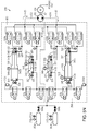
- FIGS. 4-4B are is a schematic diagram of an energy storage system 300 , employing open-air hydraulic-pneumatic principles according to one embodiment of this invention.
- the system 300 consists of one or more high-pressure gas/air storage tanks 302 a , 302 b , . . . 302 n (the number being highly variable to suit a particular application).
- Each tank 302 a , 302 b is joined in parallel via a manual valve(s) 304 a , 304 b , . . . 304 n respectively to a main air line 308 .
- the tanks 302 a , 302 b are each provided with a pressure sensor 312 a , 312 b . . .
- the controller 350 can be any acceptable control device with a human-machine interface.
- the controller 350 includes a computer 351 (for example a PC-type) that executes a stored control application 353 in the form of a computer-readable software medium.
- the control application 353 receives telemetry from the various sensors and provides appropriate feedback to control valve actuators, motors, and other needed electromechanical/electronic devices.
- An appropriate interface can be used to convert data from sensors into a form readable by the computer controller 351 (such as RS-232 or network-based interconnects). Likewise, the interface converts the computer's control signals into a form usable by valves and other actuators to perform an operation. The provision of such interfaces should be clear to those of ordinary skill in the art.
- the main air line 308 from the tanks 302 a , 302 b is coupled to a pair of multi-stage (two stages in this example) accumulator/intensifier circuits (or hydraulic-pneumatic cylinder circuits) (dashed boxes 360 , 362 ) via automatically controlled (via controller 350 ), two-position valves 307 a , 307 b , 307 c and 306 a , 306 b and 306 c . These valves are coupled to respective accumulators 316 and 317 and intensifiers 318 and 319 according to one embodiment of the system. Pneumatic valves 306 a and 307 a are also coupled to a respective atmospheric air vent 310 b and 310 a .
- valves 306 c and 307 c connect along a common air line 390 , 391 between the main air line 308 and the accumulators 316 and 317 , respectively.
- Pneumatic valves 306 b and 307 b connect between the respective accumulators 316 and 317 , and intensifiers 318 and 319 .
- Pneumatic valves 306 a , 307 a connect along the common lines 390 , 391 between the intensifiers 318 and 319 , and the atmospheric vents 310 b and 310 a.
- the air from the tanks 302 selectively communicates with the air chamber side of each accumulator and intensifier (referenced in the drawings as air chamber 340 for accumulator 316 , air chamber 341 for accumulator 317 , air chamber 344 for intensifier 318 , and air chamber 345 for intensifier 319 ).
- An air temperature sensor 322 and a pressure sensor 324 communicate with each air chamber 341 , 344 , 345 , 322 , and deliver sensor telemetry to the controller 350 .
- each accumulator 316 , 317 is enclosed by a movable piston 336 , 337 having an appropriate sealing system using sealing rings and other components that are known to those of ordinary skill in the art.
- the piston 336 , 337 moves along the accumulator housing in response to pressure differentials between the air chamber 340 , 341 and an opposing fluid chamber 338 , 339 , respectively, on the opposite side of the accumulator housing.
- hydraulic fluid or another liquid, such as water
- the air chambers 344 , 345 of the respective intensifiers 318 , 319 are enclosed by a moving piston assembly 342 , 343 .
- the intensifier air piston 342 a , 343 a is connected by a shaft, rod, or other coupling to a respective fluid piston, 342 b , 343 b .
- This fluid piston 342 b , 343 b moves in conjunction with the air piston 342 a , 343 a , but acts directly upon the associated intensifier fluid chamber 346 , 347 .
- the internal diameter (and/or volume) of the air chamber (DAI) for the intensifier 318 , 319 is greater than the diameter of the air chamber (DAA) for the accumulator 316 , 317 in the same circuit 360 , 362 .
- each intensifier fluid piston is approximately the same as the diameter of each accumulator (DFA).
- the area of the gas piston in the intensifier would be approximately 10 times the area of the piston in the accumulator (or 3.16 times the radius).
- ATM atmospheres
- the precise values for initial high-pressure, mid-pressure and final low-pressure are highly variable, depending in part upon the operating specifications of the system components, scale of the system and output requirements.
- the relative sizing of the accumulators and the intensifiers is variable to suit a particular application.
- Each fluid chamber 338 , 339 , 346 , 347 is interconnected with an appropriate temperature sensor 322 and pressure sensor 324 , each delivering telemetry to the controller 350 .
- each fluid line interconnecting the fluid chambers can be fitted with a flow sensor 326 , which directs data to the controller 350 .
- the pistons 336 , 337 , 342 and 343 can include position sensors 348 that report their present position to the controller 350 . The position of the piston can be used to determine relative pressure and flow of both gas and fluid.
- Each fluid connection from a fluid chamber 338 , 339 , 346 , 347 is connected to a pair of parallel, automatically controlled valves.
- fluid chamber 338 (accumulator 316 ) is connected to valve pair 328 c and 328 d ; fluid chamber 339 (accumulator 317 ) is connected to valve pair 329 a and 329 b ; fluid chamber 346 (intensifier 318 ) is connected to valve pair 328 a and 328 b ; and fluid chamber 347 (intensifier 319 ) is connected to valve pair 329 c and 329 d .
- One valve from each chamber 328 b , 328 d , 329 a and 329 c is connected to one connection side 372 of a hydraulic motor/pump 330 .
- This motor/pump 330 can be piston-type (or other suitable type, including vane, impeller, and gear) assembly having a shaft 331 (or other mechanical coupling) that drives, and is driven by, a combination electrical motor/generator assembly 332 .
- the motor/generator assembly 332 is interconnected with a power distribution system and can be monitored for status and output/input level by the controller 350 .
- the other connection side 374 of the hydraulic motor/pump 330 is connected to the second valve in each valve pair 328 a , 328 c , 329 b and 329 d . By selectively toggling the valves in each pair, fluid is connected between either side 372 , 374 of the hydraulic motor/pump 330 .
- some or all of the valve pairs can be replaced with one or more three position, four way valves or other combinations of valves to suit a particular application.
- the number of circuits 360 , 362 can be increased as necessary. Additional circuits can be interconnected to the tanks 302 and each side 372 , 374 of the hydraulic motor/pump 330 in the same manner as the components of the circuits 360 , 362 . Generally, the number of circuits should be even so that one circuit acts as a fluid driver while the other circuit acts as a reservoir for receiving the fluid from the driving circuit.
- An optional accumulator 366 is connected to at least one side (e.g., inlet side 372 ) of the hydraulic motor/pump 330 .
- the optional accumulator 366 can be, for example, a closed-air-type accumulator with a separate fluid side 368 and precharged air side 370 .
- the accumulator 366 acts as a fluid capacitor to deal with transients in fluid flow through the motor/pump 330 .
- a second optional accumulator or other low-pressure reservoir 371 is placed in fluid communication with the outlet side 374 of the motor/pump 330 and can also include a fluid side 371 and a precharged air side 369 .
- the foregoing optional accumulators can be used with any of the systems described herein.
- FIGS. 5A-5N For the purposes of this operational description, the illustrations of the system 300 in FIGS. 5A-5N have been simplified, omitting the controller 350 and interconnections with valves, sensors, etc. It should be understood, that the steps described are under the control and monitoring of the controller 350 based upon the rules established by the application 353 .
- FIG. 5A is a schematic diagram of the energy storage and recovery system of FIGS. 4-4B showing an initial physical state of the system 300 in which an accumulator 316 of a first circuit is filled with high-pressure gas from the high-pressure gas storage tanks 302 .
- the tanks 302 have been filled to full pressure, either by the cycle of the system 300 under power input to the hydraulic motor/pump 330 , or by a separate high-pressure air pump 376 .
- This air pump 376 is optional, as the air tanks 302 can be filled by running the recovery cycle in reverse.
- the tanks 302 in this embodiment can be filled to a pressure of 200 ATM (3000 psi) or more.
- the overall, collective volume of the tanks 302 is highly variable and depends in part upon the amount of energy to be stored.
- valve 307 c is opened allowing a flow of high-pressure air- to pass into the air chamber 340 of the accumulator 316 .
- the level of pressure is reported by the sensor 324 in communication with the chamber 340 .
- the pressure is maintained at the desired level by valve 307 c .
- This pressure causes the piston 336 to bias (arrow 800 ) toward the fluid chamber 338 , thereby generating a comparable pressure in the incompressible fluid.
- the fluid is prevented from moving out of the fluid chamber 338 at this time by valves 329 c and 329 d ).
- FIG. 5B is a schematic diagram of the energy storage and recovery system of FIGS. 4-4B showing a physical state of the system 300 following the state of FIG. 5A , in which valves are opened to allow fluid to flow from the accumulator 316 of the first circuit to the fluid motor/pump 330 to generate electricity therefrom.
- pneumatic valve 307 c remains open.
- the fluid valve 329 c is opened by the controller, causing a flow of fluid (arrow 801 ) to the inlet side 372 of the hydraulic motor/pump 330 (which operates in motor mode during the recovery phase).
- the motion of the motor 330 drives the electric motor/generator 332 in a generation mode, providing power to the facility or grid as shown by the term “POWER OUT.”
- fluid valve 328 c is opened to the fluid chamber 339 by the controller 350 to route fluid to the opposing accumulator 317 .
- the air chamber 341 is vented by opening pneumatic vent valves 306 a , 306 b . This allows any air in the chamber 341 , to escape to the atmosphere via the vent 310 b as the piston 337 moves (arrow 805 ) in response to the entry of fluid.
- FIG. 5C is a schematic diagram of the energy storage and recovery system of FIGS. 4-4B showing a physical state of the system 300 following the state of FIG. 5B , in which the accumulator 316 of the first circuit directs fluid to the fluid motor/pump 330 while the accumulator 317 of the second circuit receives exhausted fluid from the motor/pump 330 , as gas in its air chamber 341 is vented to atmosphere.
- a predetermined amount of gas has been allowed to flow from the high-pressure tanks 302 to the accumulator 316 and the controller 350 now closes pneumatic valve 307 c .
- Other valves remain open so that fluid can continue to be driven by the accumulator 316 through the motor/pump 330 .
- FIG. 5D is a schematic diagram of the energy storage and recovery system of FIGS. 4-4B showing a physical state of the system 300 following the state of FIG. 5C , in which the accumulator 316 of the first circuit continues to direct fluid to the fluid motor/pump 330 while the accumulator 317 of the second circuit continues to receive exhausted fluid from the motor/pump 330 , as gas in its air chamber 341 is vented to atmosphere.
- the operation continues, where the accumulator piston 136 drives additional fluid (arrow 800 ) through the motor/pump 330 based upon the charge of gas pressure placed in the accumulator air chamber 340 by the tanks 302 .
- the fluid causes the opposing accumulator's piston 337 to move (arrow 805 ), displacing air through the vent 310 b.
- FIG. 5E is a schematic diagram of the energy storage and recovery system of FIGS. 4-4B showing a physical state of the system 300 following the state of FIG. 5D , in which the accumulator 316 of the first circuit has nearly exhausted the fluid in its fluid chamber 338 and the gas in its air chamber 340 has expanded to nearly mid-pressure from high-pressure.
- the charge of gas in the air chamber 340 of the accumulator 316 has continued to drive fluid (arrows 800 , 801 ) through the motor/pump 330 while displacing air via the air vent 310 b .
- the gas has expanded from high-pressure to mid-pressure during this portion of the energy recovery cycle. Consequently, the fluid has ranged from high to mid-pressure.
- the rate of expansion can be controlled.
- heat transfer can occur through the walls of the accumulators and/or intensifiers, or heat-transfer mechanisms can act upon the expanding or compressing gas to absorb or radiate heat from or to an environmental or other source. The rate of this heat transfer is governed by the thermal properties and characteristics of the accumulators/intensifiers, which can be used to determine a thermal time constant.
- the accumulators can be submerged in a water bath or water/fluid flow can be circulated around the accumulators and intensifiers.
- the accumulators can alternatively be surrounded with heating/cooling coils or a flow of warm air can be blown past the accumulators/intensifiers.
- any technique that allows for mass flow transfer of heat to and from the accumulators can be employed.
- FIGS. 15A-15W For a general explanation of the effects of isothermal versus adiabatic compression and expansion and the advantages of systems and methods in accordance with the invention (ESS), see FIGS. 15A-15W .
- FIG. 5F is a schematic diagram of the energy storage and recovery system of FIGS. 4-4B , showing a physical state of the system 300 following the state of FIG. 5E in which the accumulator 316 of the first circuit has exhausted the fluid in its fluid chamber 338 and the gas in its air chamber 340 has expanded to mid-pressure from high-pressure, and the valves have been momentarily closed on both the first circuit and the second circuit, while the optional accumulator 366 delivers fluid through the motor/pump 330 to maintain operation of the electric motor/generator 332 between cycles. As shown in FIG.
- the piston 336 of the accumulator 316 has driven all fluid out of the fluid chamber 338 as the gas in the air chamber 340 has fully expanded (to mid-pressure of 20 ATM, per the example).
- Fluid valves 329 c and 328 c are closed by the controller 350 .
- the opening and closing of valves is carefully timed so that a flow through the motor/pump 330 is maintained.
- brief interruptions in fluid pressure can be accommodated by pressurized fluid flow 710 from the optional accumulator ( 366 in FIGS. 4-4B ), which is directed through the motor/pump 330 to the second optional accumulator ( 367 in FIG. 4 ) at low-pressure as an exhaust fluid flow 720 .
- the exhaust flow can be directed to a simple low-pressure reservoir that is used to refill the first accumulator 366 .
- the exhaust flow can be directed to the second optional accumulator ( 367 in FIG. 4 ) at low-pressure, which is subsequently pressurized by excess electricity (driving a compressor) or air pressure from the storage tanks 302 when it is filled with fluid.
- a larger number of accumulator/intensifier circuits e.g., three or more
- their expansion cycles can be staggered so that only one circuit is closed off at a time, allowing a substantially continuous flow from the other circuits.
- FIG. 5G is a schematic diagram of the energy storage and recovery system of FIGS. 4-4B showing a physical state of the system 300 following the state of FIG. 5F , in which pneumatic valves 307 b , 306 a are opened to allow mid-pressure gas from the air chamber 340 of the first circuit's accumulator 316 to flow into the air chamber 344 of the first circuit's intensifier 318 , while fluid from the first circuit's intensifier 318 is directed through the motor/pump 330 and exhausted fluid fills the fluid chamber 347 of second circuit's intensifier 319 , whose air chamber 345 is vented to atmosphere.
- pneumatic valve 307 b is opened, while the tank outlet valve 307 c remains closed.
- the volume of the air chamber 340 of accumulator 316 is coupled to the air chamber 344 of the intensifier 318 .
- the accumulator's air pressure has been reduced to a mid-pressure level, well below the initial charge from the tanks 302 .
- the air thus, flows (arrow 810 ) through valve 307 b to the air chamber 344 of the intensifier 318 .
- This drives the air piston 342 a (arrow 830 ). Since the area of the air-contacting piston 342 a is larger than that of the piston 336 in the accumulator 316 , the lower air pressure still generates a substantially equivalent higher fluid pressure on the smaller-area, coupled fluid piston 342 b of the intensifier 318 .
- the fluid in the fluid chamber 346 thereby flows under pressure through opened fluid valve 329 a (arrow 840 ) and into the inlet side 372 of the motor/pump 330 .
- the outlet fluid from the motor pump 330 is directed (arrow 850 ) through now-opened fluid valve 328 a to the opposing intensifier 319 .
- the fluid enters the fluid chamber 347 of the intensifier 319 , biasing (arrow 860 ) the fluid piston 343 b (and interconnected gas piston 343 a ). Any gas in the air chamber 345 of the intensifier 319 is vented through the now opened vent valve 306 a to atmosphere via the vent 310 b .
- the mid-level gas pressure in the accumulator 316 is directed (arrow 820 ) to the intensifier 318 , the piston 342 a of which drives fluid from the chamber 346 using the coupled, smaller-diameter fluid piston 342 b .
- This portion of the recovery stage maintains a reasonably high fluid pressure, despite lower gas pressure, thereby ensuring that the motor/pump 330 continues to operate within a predetermined range of fluid pressures, which is desirable to maintain optimal operating efficiencies for the given motor.
- the multi-stage circuits of this embodiment effectively restrict the operating pressure range of the hydraulic fluid delivered to the motor/pump 330 above a predetermined level despite the wide range of pressures within the expanding gas charge provided by the high-pressure tank.
- FIG. 5H is a schematic diagram of the energy storage and recovery system of FIGS. 4-4B showing a physical state of the system following the state of FIG. 5G , in which the intensifier 318 of the first circuit directs fluid to the fluid motor/pump 330 based upon mid-pressure gas from the first circuit's accumulator 316 while the intensifier 319 of the second circuit receives exhausted fluid from the motor/pump 330 , as gas in its air chamber 345 is vented to atmosphere. As shown in FIG. 5H , the gas in intensifier 318 continues to expand from mid-pressure to low-pressure. Conversely, the size differential between coupled air and fluid pistons 342 a and 342 b , respectively, causes the fluid pressure to vary between high and mid-pressure. In this manner, motor/pump operating efficiency is maintained.
- FIG. 5I is a schematic diagram of the energy storage and recovery system of FIGS. 4-4B showing a physical state of the system following the state of FIG. 5H , in which the intensifier 318 of the first circuit has almost exhausted the fluid in its fluid chamber 346 and the gas in its air chamber 344 , delivered from the first circuit's accumulator 316 , has expanded to nearly low-pressure from the mid-pressure. As discussed with respect to FIG. 5H , the gas in intensifier 318 continues to expand from mid-pressure to low-pressure. Again, the size differential between coupled air and fluid pistons 342 a and 342 b , respectively, causes the fluid pressure to vary between high and mid-pressure to maintain motor/pump operating efficiency.
- FIG. 5J is a schematic diagram of the energy storage and recovery system of FIGS. 4-4B showing a physical state of the system 300 following the state of FIG. 5I , in which the intensifier 318 of the first circuit has essentially exhausted the fluid in its fluid chamber 346 and the gas in its air chamber 344 , delivered from the first circuit's accumulator 316 , has expanded to low-pressure from the mid-pressure.
- the intensifier's piston 342 reaches full stroke, while the fluid is driven fully from high to mid-pressure in the fluid chamber 346 .
- the opposing intensifier's fluid chamber 347 has filled with fluid from the outlet side 374 of the motor/pump 330 .
- FIG. 5K is a schematic diagram of the energy storage and recovery system of FIGS. 4-4B showing a physical state of the system following the state of FIG. 5J , in which the intensifier 318 of the first circuit has exhausted the fluid in its fluid chamber 346 and the gas in its air chamber 344 has expanded to low-pressure, and the valves have been momentarily closed on both the first circuit and the second circuit in preparation of switching-over to an expansion cycle in the second circuit, whose accumulator and intensifier fluid chambers 339 , 347 are now filled with fluid.
- the optional accumulator 366 can deliver fluid through the motor/pump 330 to maintain operation of the motor/generator 332 between cycles. As shown in FIG.
- pneumatic valve 307 b located between the accumulator 316 and the intensifier 318 of the circuit 362 , is closed.
- the gas charge initiated in FIG. 5A has been fully expanded through two stages with relatively gradual, isothermal expansion characteristics, while the motor/pump 330 has received fluid flow within a desirable operating pressure range.
- the fluid valves 329 a and 328 a are momentarily closed.
- the above-described optional accumulator 366 , and/or other interconnected pneumatic/hydraulic accumulator/intensifier circuits can maintain predetermined fluid flow through the motor/pump 330 while the valves of the subject circuits 360 , 362 are momentarily closed.
- the optional accumulators and reservoirs 366 , 367 as shown in FIG. 4 , can provide a continuing flow 710 of pressure through the motor/pump 330 , and into the reservoir or low-pressure accumulator (exhaust fluid flow 720 ). The full range of pressure in the previous gas charge being utilized by the system 300 .
- FIG. 5L is a schematic diagram of the energy storage and recovery system of FIGS. 4-4B showing a physical state of the system following the state of FIG. 5K , in which the accumulator 317 of the second circuit is filled with high-pressure gas from the high-pressure tanks 302 as part of the switch-over to the second circuit as an expansion circuit, while the first circuit receives exhausted fluid and is vented to atmosphere while the optional accumulator 366 delivers fluid through the motor/pump 330 to maintain operation of the motor/generator between cycles. As shown in FIG. 5L , the cycle continues with a new charge of high-pressure (slightly lower) gas from the tanks 302 delivered to the opposing accumulator 317 .
- pneumatic valve 306 c is now opened by the controller 350 , allowing a charge of relatively high-pressure gas to flow (arrow 1310 ) into the air chamber 341 of the accumulator 317 , which builds a corresponding high-pressure charge in the air chamber 341 .
- FIG. 5M is a schematic diagram of the energy storage and recovery system of FIGS. 4-4B showing a physical state of the system following the state of FIG. 5L , in which valves are opened to allow fluid to flow from the accumulator 317 of the second circuit to the fluid motor/pump 330 to generate electricity therefrom, while the first circuit's accumulator 316 , whose air chamber 340 is vented to atmosphere, receives exhausted fluid from the motor/pump 330 . As shown in FIG.
- the pneumatic valve 306 c is closed and the fluid valves 328 d and 329 d are opened on the fluid side of the circuits 360 , 362 , thereby allowing the accumulator piston 337 to move (arrow 1410 ) under pressure of the charged air chamber 341 .
- This directs fluid under high pressure through the inlet side 372 of the motor/pump 330 (arrow 1420 ), and then through the outlet 374 .
- the exhausted fluid is directed (arrow 1430 ) now to the fluid chamber 338 of accumulator 316 .
- Pneumatic valves 307 a and 307 b have been opened, allowing the low-pressure air in the air chamber 340 of the accumulator 316 to vent (arrow 1450 ) to atmosphere via vent 310 a .
- the piston 336 of the accumulator 316 can move (arrow 1460 ) without resistance to accommodate the fluid from the motor/pump outlet 374 .
- FIG. 5N is a schematic diagram of the energy storage and recovery system of FIGS. 4-4B showing a physical state of the system following the state of FIG. 5M , in which the accumulator 317 of the second circuit 362 continues to direct fluid to the fluid motor/pump 330 while the accumulator 316 of the first circuit continues to receive exhausted fluid from the motor/pump 330 , as gas in its air chamber 340 is vented to atmosphere, the cycle eventually directing mid-pressure air to the second circuit's intensifier 319 to drain the fluid therein. As shown in FIG. 5 N, the high-pressure gas charge in the accumulator 317 expands more fully within the air chamber 341 (arrow 1410 ). Eventually, the charge in the air chamber 341 is fully expanded.
- the mid-pressure charge in the air chamber 341 is then coupled via open pneumatic valve 306 b to the intensifier 319 , which fills the opposing intensifier 318 with spent fluid from the outlet 374 .
- the process repeats until a given amount of energy is recovered or the pressure in the tanks 302 drops below a predetermined level.
- the system 300 could be run in reverse to compress gas in the tanks 302 by powering the electric generator/motor 332 to drive the motor/pump 330 in pump mode.
- the above-described process occurs in reverse order, with driven fluid causing compression within both stages of the air system in turn. That is, air is first compressed to a mid-pressure after being drawn into the intensifier from the environment. This mid-pressure air is then directed to the air chamber of the accumulator, where fluid then forces it to be compressed to high pressure. The high-pressure air is then forced into the tanks 302 .
- This compression/energy storage stage and the above-described expansion/energy recovery stages are discussed with reference to the general system state diagram shown in FIG. 6 .
- the compression and expansion cycle is predicated upon the presence of gas in the storage tanks 302 that is currently at a pressure above the mid-pressure level (e.g. above 20 ATM).
- the valves can be configured by the controller to employ only the intensifier for compression and expansion. That is, lower gas pressures are accommodated using the larger-area gas pistons on the intensifiers, while higher pressures employ the smaller-area gas pistons of the accumulators, 316 , 317 .
- high-pressure storage tanks can be implemented using standard steel or composite cylindrical pressure vessels (e.g. Compressed Natural Gas 5500-psi steel cylinders).
- the accumulators can be implemented using standard steel or composite pressure cylinders with moveable pistons (e.g., a four-inch-inner-diameter piston accumulator).
- Intensifiers pressure boosters/multipliers having characteristics similar to the exemplary accumulator can be implemented (e.g.
- a fluid motor/pump can be a standard high-efficiency axial piston, radial piston, or gear-based hydraulic motor/pump, and the associated electrical generator is also available commercially from a variety of industrial suppliers. Valves, lines, and fittings are commercially available with the specified characteristics as well.
- FIG. 6 details a generalized state diagram 600 that can be employed by the control application 353 to operate the system's valves and motor/generator based upon the direction of the energy cycle (recovery/expansion or storage/compression) based upon the reported states of the various pressure, temperature, piston-position, and/or flow sensors.
- Base State 1 ( 610 ) is a state of the system in which all valves are closed and the system is neither compressing nor expanding gas.
- a first accumulator and intensifier (e.g., 316 , 318 ) are filled with the maximum volume of hydraulic fluid and second accumulator and intensifier 1 (e.g., 317 , 319 ) are filled with the maximum volume of air, which may or may not be at a pressure greater than atmospheric.
- the physical system state corresponding to Base State 1 is shown in FIG. 5A .
- Base State 2 ( 620 ) of FIG. 6 is a state of the system in which all valves are closed and the system is neither compressing nor expanding gas.
- the second accumulator and intensifier are filled with the maximum volume of hydraulic fluid and the first accumulator and intensifier are filled with the maximum volume of air, which may or may not be at a pressure greater than atmospheric.
- the physical system state corresponding to Base State 2 is shown in FIG. 5K .
- Base State 1 and Base State 2 each link to a state termed Single Stage Compression 630 .
- This general state represents a series of states of the system in which gas is compressed to store energy, and which occurs when the pressure in the storage tanks 302 is less than the mid-pressure level. Gas is admitted (from the environment, for example) into the intensifier ( 318 or 319 -depending upon the current base state), and is then pressurized by driving hydraulic fluid into that intensifier. When the pressure of the gas in the intensifier reaches the pressure in the storage tanks 302 , the gas is admitted into the storage tanks 302 . This process repeats for the other intensifier, and the system returns to the original base state ( 610 or 620 ).
- the Two Stage Compression 632 shown in FIG. 6 represents a series of states of the system in which gas is compressed in two stages to store energy, and which occurs when the pressure in the storage tanks 302 is greater than the mid-pressure level.
- the first stage of compression occurs in an intensifier ( 318 or 319 ) in which gas is pressurized to mid-pressure after being admitted at approximately atmospheric (from the environment, for example).
- the second stage of compression occurs in accumulator ( 316 or 317 ) in which gas is compressed to the pressure in the storage tanks 302 and then allowed to flow into the storage tanks 302 .
- the system returns to the other base state from the current base state, as symbolized on the diagram by the crossing-over process arrows 634 .
- the Single State Expansion 640 represents a series of states of the system in which gas is expanded to recover stored energy and which occurs when the pressure in the storage tanks 302 is less than the mid-pressure level.
- An amount of gas from storage tanks 302 is allowed to flow directly into an intensifier ( 318 or 319 ). This gas then expands in the intensifier, forcing hydraulic fluid through the hydraulic motor/pump 330 and into the second intensifier, where the exhausted fluid moves the piston with the gas-side open to atmospheric (or another low-pressure environment).
- the Single Stage Expansion process is then repeated for the second intensifier, after which the system returns to the original base state ( 610 or 620 ).
- the Two Stage Expansion 642 represents a series of states of the system in which gas is expanded in two stages to recover stored energy and which occurs when pressure in the storage tanks is greater than the mid-pressure level.
- An amount of gas from storage tanks 302 is allowed into an accumulator ( 316 or 317 ), wherein the gas expands to mid-pressure, forcing hydraulic fluid through the hydraulic motor/pump 330 and into the second accumulator.
- the gas is then allowed into the corresponding intensifier ( 318 or 319 ), wherein the gas expands to near-atmospheric pressure, forcing hydraulic fluid through the hydraulic motor/pump 330 and into the second intensifier.
- the series of states comprising two-stage expansion are shown in the above-described FIGS. 5A-5N . Following two-stage expansion, the system returns to the other base state ( 610 or 620 ) as symbolized by the crossing process arrows 644 .
- the above-described system for storing and recovering energy is highly efficient in that it allows for gradual expansion of gas over a period that helps to maintain isothermal characteristics.
- the system particularly deals with the large expansion and compression of gas between high-pressure to near atmospheric (and the concomitant thermal transfer) by providing this compression/expansion in two or more separate stages that allow for more gradual heat transfer through the system components.
- little or no outside energy is required to run the system (heating gas, etc.), rendering the system more environmentally friendly, capable of being implemented with commercially available components, and scalable to meet a variety of energy storage/recovery needs.
- FIGS. 7A-7F depict the major systems of an alternative system/method of expansion/compression cycling an open-air staged hydraulic-pneumatic system, where the system 400 includes at least three accumulators 416 a , 416 b , 416 c , at least one intensifier 418 , and two motors/pumps 430 a , 430 b .
- the compressed gas storage tanks, valves, sensors, etc. are not shown for clarity.
- FIGS. 7A-7F illustrate the operation of the accumulators 416 , intensifier 418 , and the motors/pumps 430 during various stages of expansion ( 101 - 106 ).
- the system 400 returns to stage 101 after stage 106 is complete.
- D, F, AI, and F2 refer to whether the accumulator or intensifier is driving (D) or filling (F), with the additional labels for the accumulators where AI refers to accumulator to intensifier—the accumulator air side attached to and driving the intensifier air side, and F2 refers to filling at twice the rate of the standard filling.
- the layout consists of three equally sized hydraulic-pneumatic accumulators 416 a , 416 b , 416 c , one intensifier 418 having a hydraulic fluid side 446 with a capacity of about 1 ⁇ 3 of the accumulator capacity, and two hydraulic motor/pumps 430 a , 430 b.
- FIG. 7A represents stage or time instance 101 , where accumulator 416 a is being driven with high pressure gas from a pressure vessel. After a specific amount of compressed gas is admitted (based on the current vessel pressure), a valve will be closed, disconnecting the pressure vessel and the high pressure gas will continue to expand in accumulator 416 a as shown in FIGS. 7B and 7C (i.e., stages 102 and 103 ). Accumulator 416 b is empty of hydraulic fluid and its air chamber 440 b is unpressurized and being vented to the atmosphere.
- accumulator 416 c is at a state where gas has already been expanding for two units of time and is continuing to drive motor 430 b while filling intensifier 418 .
- Intensifier 418 similar to accumulator 416 b , is empty of hydraulic fluid and its air chamber 444 is unpressurized and being vented to the atmosphere.
- the air chamber 440 a of accumulator 416 a continues to expand, thereby forcing fluid out of the fluid chamber 438 a and driving motor/pump 430 a and filling accumulator 416 b .
- Accumulator 416 c is now empty of hydraulic fluid, but remains at mid-pressure.
- the air chamber 440 c of accumulator 416 c is now connected to the air chamber 444 of intensifier 418 .
- Intensifier 418 is now full of hydraulic fluid and the mid-pressure gas in accumulator 416 c drives the intensifier 418 , which provides intensification of the mid-pressure gas to high pressure hydraulic fluid.
- the high pressure hydraulic fluid drives motor/pump 430 b with the output of motor/pump 430 b also connected to and filling accumulator 416 b through appropriate valving.
- accumulator 416 b is filled at twice the normal rate when a single expanding hydraulic pneumatic device (accumulator or intensifier) is providing the fluid for filling.
- the system 400 has returned to a state similar to stage 101 , but with different accumulators at equivalent stages.
- Accumulator 416 b is now full of hydraulic fluid and is being driven with high pressure gas from a pressure vessel. After a specific amount of compressed gas is admitted (based on the current vessel pressure), a valve will be closed, disconnecting the pressure vessel. The high pressure gas will continue to expand in accumulator 416 b as shown in stages 104 and 105 .
- Accumulator 416 c is empty of hydraulic fluid and the air chamber 440 c is unpressurized and being vented to the atmosphere.
- accumulator 416 a is at a state where gas has already been expanding for two units of time and is continuing to drive motor/pump 430 a while now filling intensifier 418 .
- Intensifier 418 similar to accumulator 416 c , is again empty of hydraulic fluid and the air chamber 444 is unpressurized and being vented to the atmosphere.
- the air chamber 440 b of accumulator 416 b continues to expand, thereby forcing fluid out of the fluid chamber 438 b and driving motor/pump 430 a and filling accumulator 416 c .
- Accumulator 416 a is now empty of hydraulic fluid, but remains at mid-pressure.
- the air chamber 440 a of accumulator 416 a is now connected to the air chamber 444 of intensifier 418 .
- Intensifier 418 is now full of hydraulic fluid and the mid-pressure gas in accumulator 416 a drives the intensifier 418 , which provides intensification of the mid-pressure gas to high pressure hydraulic fluid.
- the high pressure hydraulic fluid drives motor/pump 430 b with the output of motor/pump 430 b also connected to and filling accumulator 416 c through appropriate valving.
- accumulator 416 c is filled at twice the normal rate when a single expanding hydraulic pneumatic device (accumulator or intensifier) is providing the fluid for filling.
- the system 400 has returned to a state similar to stage 103 , but with different accumulators at equivalent stages.
- Accumulator 416 c is now full of hydraulic fluid and is being driven with high pressure gas from a pressure vessel. After a specific amount of compressed gas is admitted (based on the current vessel pressure), a valve will be closed, disconnecting the pressure vessel. The high pressure gas will continue to expand in accumulator 416 c .
- Accumulator 416 a is empty of hydraulic fluid and the air chamber 440 a is unpressurized and being vented to the atmosphere.
- accumulator 416 b is at a state where gas has already been expanding for two units of time and is continuing to drive motor/pump 430 a while filling accumulator 416 a with hydraulic fluid via appropriate valving.
- Intensifier 418 similar to accumulator 416 a , is again empty of hydraulic fluid and the air chamber 444 is unpressurized and being vented to the atmosphere.
- the air chamber 440 c of accumulator 416 c continues to expand, thereby forcing fluid out of the fluid chamber 438 c and driving motor/pump 430 b and filling accumulator 416 a .
- Accumulator 416 b is now empty of hydraulic fluid, but remains at mid-pressure.
- the air chamber 440 b of accumulator 416 b is now connected to the air chamber 444 of intensifier 418 .
- Intensifier 418 is now full of hydraulic fluid and the mid-pressure gas in accumulator 416 b drives the intensifier 418 , which provides intensification of the mid-pressure gas to high pressure hydraulic fluid.
- the high pressure hydraulic fluid drives motor/pump 430 a with the output of motor/pump 430 a also connected to and filling accumulator 416 a through appropriate valving.
- accumulator 416 a is filled at twice the normal rate when a single expanding hydraulic pneumatic device (accumulator or intensifier) is providing the fluid for filling.
- FIG. 8 is a table illustrating the expansion scheme described above and illustrated in FIGS. 7A-7F for a three accumulator, one intensifier system. It should be noted that throughout the cycle, two hydraulic-pneumatic devices (two accumulators or one intensifier plus one accumulator) are always expanding and the two motors are always being driven, but at different points in the expansion, such that the overall power remains relatively constant.
- FIG. 9 is a graph illustrating the power versus time profile for the expansion scheme described above and illustrated in FIGS. 7A-7F for a three accumulator-one intensifier system.
- the power outputs for accumulator 416 a , accumulator 416 b , accumulator 416 c , and intensifier 418 are represented as linear responses that decrease as the pressure in each device decreases. While this is a relative representation and depends greatly on the actual components and expansion scheme used, the general trend is shown. As shown in FIG. 9 , the staging of the expansion allows for a relatively constant power output and an efficient use of resources.
- FIG. 10 is a table illustrating an expansion scheme for a four accumulator-two intensifier system. It should be noted that throughout the cycle, at a minimum three hydraulic-pneumatic devices (at least two accumulators and one intensifier) are always expanding, but each starts at different time instances, such that the overall power is high and remains relatively constant.
- This alternative system for expansion improves the power output by approximately two times over the systems for expansion described above.
- the system while essentially doubling the power output over the alternative systems, only does so for system pressures above the mid-pressure.
- the three accumulators-one intensifier scheme reduces the system depth of discharge from nearly atmospheric (e.g., for the two accumulator two intensifier scheme) to the mid-pressure, reducing the system energy density by approximately 10%.
- FIGS. 11 and 12 are schematic and pictorial representations, respectively, of one exemplary embodiment of a compressed gas-based energy storage system using a staged hydraulic-pneumatic energy conversion system that can provide approximately 5 kW of power.
- the system 200 is similar to those described with respect to FIGS. 1 and 4 , with different control valve arrangements.
- the operation of the system is also substantially similar to the system 300 described in FIGS. 4-6 .
- the system 200 includes five high-pressure gas/air storage tanks 202 a - 202 e .
- Tanks 202 a and 202 b and tanks 202 c and 202 d are joined in parallel via manual valves 204 a , 204 b and 204 c , 204 d , respectively.
- Tank 202 e also includes a manual shut-off valve 204 e .
- the tanks 202 are joined to a main air line 208 via automatically controlled pneumatic two-way (i.e., shut-off) valves 206 a , 206 b , 206 c to a main air line 308 .
- the tank output lines include pressure sensors 212 a , 212 b , 212 c .
- the lines/tanks 202 could also include temperature sensors.
- the various sensors can be monitored by a system controller 220 via appropriate connections, as described hereinabove.
- the main air line 208 is coupled to a pair of multi-stage (two stages in this example) accumulator circuits via automatically controlled pneumatic shut-off valves 207 a , 207 b . These valves 207 a , 207 b are coupled to respective accumulators 216 and 217 .
- the air chambers 240 , 241 of the accumulators 216 , 217 are connected, via automatically controlled pneumatic shut-offs 207 c , 207 d , to the air chambers 244 , 245 of the intensifiers 218 , 219 .
- Pneumatic shut-off valves 207 e , 207 f are also coupled to the air line connecting the respective accumulator and intensifier air chambers and to a respective atmospheric air vent 210 a , 210 b .
- This arrangement allows for air from the various tanks 202 to be selectively directed to either accumulator air chamber 244 , 245 .
- the various air lines and air chambers can include pressure and temperature sensors 222 224 that deliver sensor telemetry to the controller 220 .
- each accumulator 216 , 217 is enclosed by a movable piston 236 , 237 having an appropriate sealing system using sealing rings and other components that are known to those of ordinary skill in the art.
- the piston 236 , 237 moves along the accumulator housing in response to pressure differentials between the air chamber 240 , 241 and an opposing fluid chamber 238 , 239 , respectively, on the opposite side of the accumulator housing.
- the air chambers 244 , 245 of the respective intensifiers 218 , 219 are also enclosed by a moving piston assembly 242 , 243 .
- the piston assembly 242 , 243 includes an air piston 242 a , 243 a connected by a shaft, rod, or other coupling to a respective fluid piston, 242 b , 243 b that move in conjunction.
- the differences between the piston diameters allows a lower air pressure acting upon the air piston to generate a similar pressure on the associated fluid chamber as the higher air pressure acting on the accumulator piston.
- the system allows for at least two stages of pressure to be employed to generate similar levels of fluid pressure.
- the accumulator fluid chambers 238 , 239 are interconnected to a hydraulic motor/pump arrangement 230 via a hydraulic valve 228 a .
- the hydraulic motor/pump arrangement 230 includes a first port 231 and a second port 233 .
- the arrangement 230 also includes several optional valves, including a normally open shut-off valve 225 , a pressure relief valve 227 , and three check valves 229 that can further control the operation of the motor/pump arrangement 230 .
- check valves 229 a , 229 b direct fluid flow from the motor/pump's leak port to the port 231 , 233 at a lower pressure.
- valves 225 , 229 c prevent the motor/pump from coming to a hard stop during an expansion cycle.
- the hydraulic valve 228 a is shown as a 3-position, 4-way directional valve that is electrically actuated and spring returned to a center closed position, where no flow through the valve 228 a is possible in the unactuated state.
- the directional valve 228 a controls the fluid flow from the accumulator fluid chambers 238 , 239 to either the first port 231 or the second port 233 of the motor/pump arrangement 230 . This arrangement allows fluid from either accumulator fluid chamber 238 , 239 to drive the motor/pump 230 clockwise or counter-clockwise via a single valve.
- the intensifier fluid chambers 246 , 247 are also interconnected to the hydraulic motor/pump arrangement 230 via a hydraulic valve 228 b .
- the hydraulic valve 228 b is also a 3-position, 4-way directional valve that is electrically actuated and spring returned to a center closed position, where no flow through the valve 228 b is possible in the unactuated state.
- the directional valve 228 b controls the fluid flow from the intensifier fluid chambers 246 , 247 to either the first port 231 or the second port 233 of the motor/pump arrangement 230 . This arrangement allows fluid from either intensifier fluid chamber 246 , 247 to drive the motor/pump 230 clockwise or counter-clockwise via a single valve.
- the motor/pump 230 can be coupled to an electrical generator/motor and that drives, and is driven by the motor/pump 230 .
- the generator/motor assembly can be interconnected with a power distribution system and can be monitored for status and output/input level by the controller 220 .
- fluid lines and fluid chambers can include pressure, temperature, or flow sensors and/or indicators 222 224 that deliver sensor telemetry to the controller 220 and/or provide visual indication of an operational state.
- the pistons 236 , 237 , 242 a , 243 a can include position sensors 248 that report their present position to the controller 220 . The position of the piston can be used to determine relative pressure and flow of both gas and fluid.
- the system 200 includes a frame or supporting structure 201 that can be used for mounting and/or housing the various components.
- the high pressure gas storage 202 includes five 10 gallon pressure vessels (for example, standard 3000 psi laboratory compressed air cylinders).
- the power conversion system includes two 1.5 gallon accumulators 216 , 217 (for example, 3,000 psi, 4′′ bore, 22′′ stroke, as available from Parker-Hannifin, Cleveland, Ohio) and two 15 gallon intensifiers 218 , 219 (for example, air side: 250 psi, 14′′ bore, 22′′ stroke; hydraulic side: 3000 psi, 4′′ bore, 22′′ stroke, as available from Parker-Hannifin, Cleveland, Ohio).
- the various sensors can be, for example, transducers and/or analog gauges as available from, for example, Omega Engineering, Inc., Stamford, Conn. for pressure, Nanmac Corporation, Framingham, Mass. for temperature, Temposonic, MTS Sensors, Cary, N.C. for position, CR Magnetics, 5310-50, St. Louis, Mo. for voltage, and LEM, Hass 200, Switzerland for current.
- the various valves and valve controls to automate the system will be sized and selected to suit a particular application and can be obtained from Parker-Hannifin, Cleveland, Ohio.
- the hydraulic motor/pump 230 can be a 10 cc/rev, F11-10, axial piston pump, as available from Parker-Hannifin.
- the electric generator/motor can be a nominal 24 Volt, 400 Amp high efficiency brushless SolidSlot 24 DC motor with a NPS6000 buck boost regulator, as available from Ecycle, Inc., Temple, Pa.
- the controller 220 can include an USB data acquisition block (available from Omega Instruments) used with a standard PC running software created using the LabVIEW® software (as available from National Instruments Corporation, Austin Tex.) and via closed loop control of pneumatically actuated valves (available from Parker-Hannifin) driven by 100 psi air that allow 50 millisecond response times to be achieved.
- an USB data acquisition block available from Omega Instruments
- LabVIEW® software available from National Instruments Corporation, Austin Tex.
- closed loop control of pneumatically actuated valves available from Parker-Hannifin
- FIGS. 13A and 13B are graphical representations of the pressures in the various components through 13 energy storage (i.e., compression) cycles ( FIG. 13A ) and eight energy recovery (i.e., expansion) cycles ( FIG. 13B ).
- the accumulators' pressures are shown in solid lines (light and dark solid lines to differentiate between the two accumulators), intensifiers' pressures are shown in dashed lines (light and dark dashed lines to differentiate between the two intensifiers), and the compressed gas storage tank pressures are shown in dotted lines.
- the accumulators and intensifiers are identified as A1, A2 and I1, I2, respectively, to identify the first accumulator/intensifier cycled and the second accumulator/intensifier cycled.
- the graphs represent the pressures as they exist in the accumulators and intensifiers as the pressure in the storage tank increases and decreases, corresponding to compression and expansion cycles.
- the basic operation of the system is described with respect to FIGS. 4-6 .
- a full expansion cycle as shown in FIG. 13B , consists of air admitted from a high pressure gas bottle and expanded from high pressure to mid pressure in one accumulator and from mid-pressure to atmospheric pressure in an intensifier, followed by an expansion in a second accumulator and intensifier which returns the system to its original state.
- the pressure and energy stored in the tanks increases, and likewise during expansion decreases, as indicated in the graphs.
- FIGS. 14A and 14B are graphical representations of the corresponding pneumatic and hydraulic pressures in the various components of the system 200 of FIG. 11 through four energy recovery (i.e., expansion) cycles.
- the accumulators' pressures are shown in solid lines (light and dark solid lines to differentiate between the two accumulators), intensifiers' pressures are shown in dashed lines (light and dark dashed lines to differentiate between the two intensifiers), and the compressed gas storage tank pressures are shown in dotted lines.
- the graph of FIG. 14A represents the gas pressures of the accumulators 216 , 217 , the intensifiers 218 , 219 , and the tank 202 during expansion.
- the graph of FIG. 14B represents the corresponding hydraulic pressures of the accumulators 216 , 217 and the intensifiers 218 , 219 during the same expansion cycles.
- the intensification stage keeps the hydraulic pressures high even when the gas pressures drop towards atmospheric.
- the surface area of the gas piston and fluid piston within an accumulator need not be the same.
- the intensifier provides a larger air piston surface area versus fluid piston area than the area differential of the accumulator's air and fluid pistons.
- the working gas is air herein, it is contemplated that high and low-pressure reservoirs of a different gas can be employed in alternative embodiments to improve heat-transfer or other system characteristics.
- piston components are used to transmit energy between the fluid and gas in both accumulators and intensifiers, it is contemplated that any separating boundary that prevents mixing of the media (fluid and gas), and that transmits mechanical energy therebetween based upon relative pressures can be substituted.
- the term “piston” can be taken broadly to include such energy transmitting boundaries. Accordingly, the described embodiments are to be considered in all respects as only illustrative and not restrictive.
Abstract
Description
Claims (23)
Priority Applications (4)
| Application Number | Priority Date | Filing Date | Title |
|---|---|---|---|
| US12/945,398 US7900444B1 (en) | 2008-04-09 | 2010-11-12 | Systems and methods for energy storage and recovery using compressed gas |
| US13/012,323 US8209974B2 (en) | 2008-04-09 | 2011-01-24 | Systems and methods for energy storage and recovery using compressed gas |
| US13/488,787 US8713929B2 (en) | 2008-04-09 | 2012-06-05 | Systems and methods for energy storage and recovery using compressed gas |
| US14/048,253 US20140047825A1 (en) | 2008-04-09 | 2013-10-08 | Systems and methods for energy storage and recovery using compressed gas |
Applications Claiming Priority (4)
| Application Number | Priority Date | Filing Date | Title |
|---|---|---|---|
| US4363008P | 2008-04-09 | 2008-04-09 | |
| US14869109P | 2009-01-30 | 2009-01-30 | |
| US12/421,057 US7832207B2 (en) | 2008-04-09 | 2009-04-09 | Systems and methods for energy storage and recovery using compressed gas |
| US12/945,398 US7900444B1 (en) | 2008-04-09 | 2010-11-12 | Systems and methods for energy storage and recovery using compressed gas |
Related Parent Applications (1)
| Application Number | Title | Priority Date | Filing Date |
|---|---|---|---|
| US12/421,057 Continuation US7832207B2 (en) | 2008-04-09 | 2009-04-09 | Systems and methods for energy storage and recovery using compressed gas |
Related Child Applications (1)
| Application Number | Title | Priority Date | Filing Date |
|---|---|---|---|
| US13/012,323 Continuation US8209974B2 (en) | 2008-04-09 | 2011-01-24 | Systems and methods for energy storage and recovery using compressed gas |
Publications (2)
| Publication Number | Publication Date |
|---|---|
| US7900444B1 true US7900444B1 (en) | 2011-03-08 |
| US20110056193A1 US20110056193A1 (en) | 2011-03-10 |
Family
ID=41057391
Family Applications (5)
| Application Number | Title | Priority Date | Filing Date |
|---|---|---|---|
| US12/421,057 Expired - Fee Related US7832207B2 (en) | 2008-04-09 | 2009-04-09 | Systems and methods for energy storage and recovery using compressed gas |
| US12/945,398 Expired - Fee Related US7900444B1 (en) | 2008-04-09 | 2010-11-12 | Systems and methods for energy storage and recovery using compressed gas |
| US13/012,323 Expired - Fee Related US8209974B2 (en) | 2008-04-09 | 2011-01-24 | Systems and methods for energy storage and recovery using compressed gas |
| US13/488,787 Expired - Fee Related US8713929B2 (en) | 2008-04-09 | 2012-06-05 | Systems and methods for energy storage and recovery using compressed gas |
| US14/048,253 Abandoned US20140047825A1 (en) | 2008-04-09 | 2013-10-08 | Systems and methods for energy storage and recovery using compressed gas |
Family Applications Before (1)
| Application Number | Title | Priority Date | Filing Date |
|---|---|---|---|
| US12/421,057 Expired - Fee Related US7832207B2 (en) | 2008-04-09 | 2009-04-09 | Systems and methods for energy storage and recovery using compressed gas |
Family Applications After (3)
| Application Number | Title | Priority Date | Filing Date |
|---|---|---|---|
| US13/012,323 Expired - Fee Related US8209974B2 (en) | 2008-04-09 | 2011-01-24 | Systems and methods for energy storage and recovery using compressed gas |
| US13/488,787 Expired - Fee Related US8713929B2 (en) | 2008-04-09 | 2012-06-05 | Systems and methods for energy storage and recovery using compressed gas |
| US14/048,253 Abandoned US20140047825A1 (en) | 2008-04-09 | 2013-10-08 | Systems and methods for energy storage and recovery using compressed gas |
Country Status (3)
| Country | Link |
|---|---|
| US (5) | US7832207B2 (en) |
| EP (1) | EP2280841A2 (en) |
| WO (1) | WO2009126784A2 (en) |
Cited By (44)
| Publication number | Priority date | Publication date | Assignee | Title |
|---|---|---|---|---|
| US20090273191A1 (en) * | 2008-05-01 | 2009-11-05 | Plant Jr William R | Power producing device utilizing fluid driven pump |
| US20100089063A1 (en) * | 2008-04-09 | 2010-04-15 | Sustainx, Inc. | Systems and Methods for Energy Storage and Recovery Using Rapid Isothermal Gas Expansion and Compression |
| US20100205960A1 (en) * | 2009-01-20 | 2010-08-19 | Sustainx, Inc. | Systems and Methods for Combined Thermal and Compressed Gas Energy Conversion Systems |
| US20100229544A1 (en) * | 2009-03-12 | 2010-09-16 | Sustainx, Inc. | Systems and Methods for Improving Drivetrain Efficiency for Compressed Gas Energy Storage |
| US20100251711A1 (en) * | 2007-10-03 | 2010-10-07 | Isentropic Limited | Energy Storage |
| US20100307156A1 (en) * | 2009-06-04 | 2010-12-09 | Bollinger Benjamin R | Systems and Methods for Improving Drivetrain Efficiency for Compressed Gas Energy Storage and Recovery Systems |
| US20110017164A1 (en) * | 2009-07-21 | 2011-01-27 | International Truck Intellectual Property Company, Llc | Vehicle hybridization system |
| US20110061836A1 (en) * | 2009-05-22 | 2011-03-17 | Ingersoll Eric D | Compressor and/or Expander Device |
| US20110107755A1 (en) * | 2009-09-11 | 2011-05-12 | Mcbride Troy O | Energy storage and generation systems and methods using coupled cylinder assemblies |
| US20110131966A1 (en) * | 2009-11-03 | 2011-06-09 | Mcbride Troy O | Systems and methods for compressed-gas energy storage using coupled cylinder assemblies |
| US20110219760A1 (en) * | 2008-04-09 | 2011-09-15 | Mcbride Troy O | Systems and methods for energy storage and recovery using compressed gas |
| US8080895B1 (en) * | 2007-10-12 | 2011-12-20 | Williams Brian B | Energy generation from compressed fluids |
| US8104274B2 (en) | 2009-06-04 | 2012-01-31 | Sustainx, Inc. | Increased power in compressed-gas energy storage and recovery |
| US8161741B2 (en) | 2009-12-24 | 2012-04-24 | General Compression, Inc. | System and methods for optimizing efficiency of a hydraulically actuated system |
| US8171728B2 (en) | 2010-04-08 | 2012-05-08 | Sustainx, Inc. | High-efficiency liquid heat exchange in compressed-gas energy storage systems |
| US8191362B2 (en) | 2010-04-08 | 2012-06-05 | Sustainx, Inc. | Systems and methods for reducing dead volume in compressed-gas energy storage systems |
| US8234863B2 (en) | 2010-05-14 | 2012-08-07 | Sustainx, Inc. | Forming liquid sprays in compressed-gas energy storage systems for effective heat exchange |
| US8240146B1 (en) | 2008-06-09 | 2012-08-14 | Sustainx, Inc. | System and method for rapid isothermal gas expansion and compression for energy storage |
| US8240140B2 (en) | 2008-04-09 | 2012-08-14 | Sustainx, Inc. | High-efficiency energy-conversion based on fluid expansion and compression |
| US8250863B2 (en) | 2008-04-09 | 2012-08-28 | Sustainx, Inc. | Heat exchange with compressed gas in energy-storage systems |
| US8272212B2 (en) | 2011-11-11 | 2012-09-25 | General Compression, Inc. | Systems and methods for optimizing thermal efficiencey of a compressed air energy storage system |
| US8359856B2 (en) | 2008-04-09 | 2013-01-29 | Sustainx Inc. | Systems and methods for efficient pumping of high-pressure fluids for energy storage and recovery |
| US8448433B2 (en) | 2008-04-09 | 2013-05-28 | Sustainx, Inc. | Systems and methods for energy storage and recovery using gas expansion and compression |
| US8454321B2 (en) | 2009-05-22 | 2013-06-04 | General Compression, Inc. | Methods and devices for optimizing heat transfer within a compression and/or expansion device |
| US8474255B2 (en) | 2008-04-09 | 2013-07-02 | Sustainx, Inc. | Forming liquid sprays in compressed-gas energy storage systems for effective heat exchange |
| US8479505B2 (en) | 2008-04-09 | 2013-07-09 | Sustainx, Inc. | Systems and methods for reducing dead volume in compressed-gas energy storage systems |
| US8495872B2 (en) | 2010-08-20 | 2013-07-30 | Sustainx, Inc. | Energy storage and recovery utilizing low-pressure thermal conditioning for heat exchange with high-pressure gas |
| US8522538B2 (en) | 2011-11-11 | 2013-09-03 | General Compression, Inc. | Systems and methods for compressing and/or expanding a gas utilizing a bi-directional piston and hydraulic actuator |
| US8539763B2 (en) | 2011-05-17 | 2013-09-24 | Sustainx, Inc. | Systems and methods for efficient two-phase heat transfer in compressed-air energy storage systems |
| US8567303B2 (en) | 2010-12-07 | 2013-10-29 | General Compression, Inc. | Compressor and/or expander device with rolling piston seal |
| US8572959B2 (en) | 2011-01-13 | 2013-11-05 | General Compression, Inc. | Systems, methods and devices for the management of heat removal within a compression and/or expansion device or system |
| US8578708B2 (en) | 2010-11-30 | 2013-11-12 | Sustainx, Inc. | Fluid-flow control in energy storage and recovery systems |
| US8667792B2 (en) | 2011-10-14 | 2014-03-11 | Sustainx, Inc. | Dead-volume management in compressed-gas energy storage and recovery systems |
| US8677744B2 (en) | 2008-04-09 | 2014-03-25 | SustaioX, Inc. | Fluid circulation in energy storage and recovery systems |
| US20140216022A1 (en) * | 2013-02-01 | 2014-08-07 | North China Electric Power University | Compressed Air Energy Storage System and Method |
| US8997475B2 (en) | 2011-01-10 | 2015-04-07 | General Compression, Inc. | Compressor and expander device with pressure vessel divider baffle and piston |
| US9074577B2 (en) | 2013-03-15 | 2015-07-07 | Dehlsen Associates, Llc | Wave energy converter system |
| US9109512B2 (en) | 2011-01-14 | 2015-08-18 | General Compression, Inc. | Compensated compressed gas storage systems |
| US20150280628A1 (en) * | 2013-11-08 | 2015-10-01 | Joseph Sajan Jacob | Digital power plant |
| US9243558B2 (en) | 2012-03-13 | 2016-01-26 | Storwatts, Inc. | Compressed air energy storage |
| US20160123331A1 (en) * | 2014-10-31 | 2016-05-05 | Martin Eugene Nix | Solar and wind powered blower utilizing a flywheel and turbine |
| US20160187891A1 (en) * | 2014-12-30 | 2016-06-30 | Thomas Michael Reilly | Hydrostatic Pressure Exchanger |
| US9835145B1 (en) | 2011-10-25 | 2017-12-05 | Walter B. Freeman | Thermal energy recovery systems |
| US10208737B1 (en) | 2011-10-25 | 2019-02-19 | Walter B. Freeman | Uniformly pressurized thermal energy recovery systems |
Families Citing this family (73)
| Publication number | Priority date | Publication date | Assignee | Title |
|---|---|---|---|---|
| EP1971773A1 (en) * | 2005-12-07 | 2008-09-24 | The University Of Nottingham | Power generation |
| US7843076B2 (en) * | 2006-11-29 | 2010-11-30 | Yshape Inc. | Hydraulic energy accumulator |
| US8525361B1 (en) * | 2008-10-06 | 2013-09-03 | Cypress Envirosystems, Inc. | Pneumatic energy harvesting devices, methods and systems |
| US8247915B2 (en) | 2010-03-24 | 2012-08-21 | Lightsail Energy, Inc. | Energy storage system utilizing compressed gas |
| US8196395B2 (en) * | 2009-06-29 | 2012-06-12 | Lightsail Energy, Inc. | Compressed air energy storage system utilizing two-phase flow to facilitate heat exchange |
| US8436489B2 (en) | 2009-06-29 | 2013-05-07 | Lightsail Energy, Inc. | Compressed air energy storage system utilizing two-phase flow to facilitate heat exchange |
| US8146354B2 (en) * | 2009-06-29 | 2012-04-03 | Lightsail Energy, Inc. | Compressed air energy storage system utilizing two-phase flow to facilitate heat exchange |
| US9146141B2 (en) * | 2009-09-23 | 2015-09-29 | The Boeing Company | Pneumatic energy harvesting and monitoring |
| US10924042B2 (en) * | 2009-09-23 | 2021-02-16 | The Boeing Company | Pneumatic energy harvesting and monitoring |
| US20110146302A1 (en) * | 2009-12-21 | 2011-06-23 | Newman Michael D | Cryogenic heat exchanger for thermoacoustic refrigeration system |
| US20110197828A1 (en) * | 2010-02-15 | 2011-08-18 | Zoran Iskrenovic | Power Generation Using Water Pressure |
| RU2434159C1 (en) * | 2010-03-17 | 2011-11-20 | Александр Анатольевич Строганов | Conversion method of heat to hydraulic energy and device for its implementation |
| US8534058B2 (en) * | 2010-05-14 | 2013-09-17 | Southwest Research Institute | Energy storage and production systems, apparatus and methods of use thereof |
| DE102010021822B3 (en) * | 2010-05-28 | 2011-07-21 | Kapelski, Rainer, 24401 | Completely autonomous lashing platform |
| GB201012743D0 (en) * | 2010-07-29 | 2010-09-15 | Isentropic Ltd | Valves |
| US20120198829A1 (en) * | 2011-02-04 | 2012-08-09 | Francois Gagnon | Energy management system using hydraulic compensator for the production of electricity from one or several networks of cynetic energy sources |
| US9109614B1 (en) * | 2011-03-04 | 2015-08-18 | Lightsail Energy, Inc. | Compressed gas energy storage system |
| FR2972504B1 (en) * | 2011-03-09 | 2014-06-27 | Olaer Ind Sa | INSTALLATION COMPRISING AT LEAST ONE HYDROPNEUMATIC ACCUMULATOR WITH AUTOMATED MAINTENANCE |
| DE102011018679A1 (en) * | 2011-04-21 | 2012-10-25 | Dennis Patrick Steel | System for storing renewable energy in e.g. wind power plant, has heat exchanger system receiving, storing and delivering heat/cold produced during compression/relaxation of gas, where system is operated as opened or closed system |
| JP2014515339A (en) * | 2011-05-23 | 2014-06-30 | ストレワット | Device for storing and delivering fluid and method for storing and delivering compressed gas contained in such device |
| DE102011105542B4 (en) * | 2011-06-24 | 2014-10-30 | Adensis Gmbh | Method and device for energy storage by means of a combined heat and pressure accumulator |
| EP2574756B1 (en) * | 2011-09-30 | 2020-06-17 | Deutsches Zentrum für Luft- und Raumfahrt e.V. | Method for operating an adiabatic compressed air storage power plant and adiabatic compressed air storage power plant |
| WO2013054262A1 (en) * | 2011-10-10 | 2013-04-18 | Angus Peter Robson | Accumulator |
| US10570930B2 (en) | 2011-10-10 | 2020-02-25 | Angus Peter Robson | Accumulator |
| US9243585B2 (en) | 2011-10-18 | 2016-01-26 | Lightsail Energy, Inc. | Compressed gas energy storage system |
| US20130152572A1 (en) | 2011-12-16 | 2013-06-20 | Jeffrey Madderno | Valve activation in compressed-gas energy storage and recovery systems |
| US8965594B2 (en) | 2012-01-19 | 2015-02-24 | General Compression, Inc. | System and method for conserving energy resources through storage and delivery of renewable energy |
| US9843237B2 (en) | 2012-03-26 | 2017-12-12 | Rotonix Hong Kong Limited | Electromechanical flywheel with evacuation system |
| KR20140143739A (en) * | 2012-03-26 | 2014-12-17 | 로테너지 홀딩스, 엘티디 | Electromechanical flywheel with evacuation features |
| CN103679494B (en) | 2012-09-17 | 2018-04-03 | 阿里巴巴集团控股有限公司 | Commodity information recommendation method and device |
| US8726629B2 (en) | 2012-10-04 | 2014-05-20 | Lightsail Energy, Inc. | Compressed air energy system integrated with gas turbine |
| JP2016519731A (en) | 2013-03-04 | 2016-07-07 | エコージェン パワー システムズ エル.エル.シー.Echogen Power Systems, L.L.C. | Heat engine system with high net power supercritical carbon dioxide circuit |
| US9234530B1 (en) * | 2013-03-13 | 2016-01-12 | Exelis Inc. | Thermal energy recovery |
| US8851043B1 (en) | 2013-03-15 | 2014-10-07 | Lightsail Energy, Inc. | Energy recovery from compressed gas |
| EP3036118B1 (en) * | 2013-08-21 | 2024-01-10 | RTX Corporation | Environmental control generator system and apparatus |
| CN103956947A (en) * | 2014-03-24 | 2014-07-30 | 山东理工大学 | Mineral aggregate conveyor belt gravitational potential energy recovery power generation system |
| CN104165067A (en) * | 2014-07-25 | 2014-11-26 | 北京航空航天大学 | Cold recovery method for vaporization heat absorption-compression heat release coupling |
| JP6368577B2 (en) * | 2014-07-31 | 2018-08-01 | 株式会社神戸製鋼所 | Compressed air storage power generation apparatus and compressed air storage power generation method |
| US10570777B2 (en) | 2014-11-03 | 2020-02-25 | Echogen Power Systems, Llc | Active thrust management of a turbopump within a supercritical working fluid circuit in a heat engine system |
| DE102014226406A1 (en) * | 2014-12-18 | 2016-06-23 | Zf Friedrichshafen Ag | hybrid vehicle |
| SE541880C2 (en) * | 2015-01-19 | 2020-01-02 | Noditech Ab | Device in a heating cycle for the conversion of heat into electrical energy |
| US10294861B2 (en) | 2015-01-26 | 2019-05-21 | Trent University | Compressed gas energy storage system |
| DE102015001139A1 (en) * | 2015-01-29 | 2016-08-18 | Linde Aktiengesellschaft | Method and device for filling a gas pressure accumulator |
| DE102015207349B4 (en) | 2015-04-22 | 2021-12-23 | hte GmbH the high througput experimentation Co. | Device and method for providing compressed gases with an integrated piston compressor |
| FR3036887B1 (en) * | 2015-06-01 | 2017-07-14 | Segula Eng & Consulting | DEVICE AND METHOD FOR ENERGY CONVERSION AND ENERGY STORAGE OF ELECTRIC ORIGIN, IN THE FORM OF COMPRESSED AIR |
| US9850852B2 (en) | 2015-07-30 | 2017-12-26 | Third Shore Group, LLC | Compressed gas capture and recovery system |
| ES2827311T3 (en) | 2015-09-08 | 2021-05-20 | Univ California | Low cost hybrid energy storage system |
| DE102015222983A1 (en) | 2015-11-20 | 2017-05-24 | Robert Bosch Gmbh | Energy storage system |
| ES2688211T3 (en) | 2015-12-22 | 2018-10-31 | Renestor-M Gmbh | Energy storage and recovery system |
| WO2017127678A1 (en) * | 2016-01-20 | 2017-07-27 | Nexmatix Llc | Four-way control valve for pneumatic charging and discharging of working vessel |
| CN105626355B (en) * | 2016-01-27 | 2018-05-25 | 华北电力大学 | Self-adaptive hydraulic potential energy conversion equipment |
| EP3228861B1 (en) * | 2016-03-29 | 2020-02-19 | PHD, Inc. | Actuator exhaust fluid energy harvester |
| DE102016106733A1 (en) * | 2016-04-12 | 2017-10-12 | Atlas Copco Energas Gmbh | Method and installation for energy conversion of pressure energy into electrical energy |
| EP3574191A4 (en) | 2017-01-30 | 2020-11-04 | The Regents of the University of California | Storage-combined cold, heat and power |
| CN107816827B (en) * | 2017-11-30 | 2023-09-12 | 安徽安凯汽车股份有限公司 | Auxiliary installation device for condenser |
| US10837360B2 (en) | 2018-03-13 | 2020-11-17 | Maxim Raskin | System for energy storage and recovery |
| CN108266324B (en) * | 2018-03-21 | 2024-02-13 | 济宁圣峰环宇新能源技术有限公司 | Energy superposition storage system of wind power generator |
| PL240888B1 (en) * | 2018-06-26 | 2022-06-20 | Akademia Gorniczo Hutnicza Im Stanislawa Staszica W Krakowie | System and method for recovery of compressed gas waste energy |
| US10883388B2 (en) | 2018-06-27 | 2021-01-05 | Echogen Power Systems Llc | Systems and methods for generating electricity via a pumped thermal energy storage system |
| US20200080538A1 (en) * | 2018-09-11 | 2020-03-12 | Hector Carroll, LLC | Apparatus and Method for Generating Electricity With Pressurized Water and Air Flow Media |
| WO2020123941A1 (en) | 2018-12-14 | 2020-06-18 | Go Team CCR LLC | Apparatus and method for generation of electricity with pressurized water and air flow media |
| US11441530B2 (en) | 2018-12-14 | 2022-09-13 | Carroll Hector, Llc | Pumped storage water electric power generation facilities |
| US11280311B2 (en) | 2018-12-14 | 2022-03-22 | Carroll Hector, Llc | Pumped storage water electric power generation facility and reservoir utilizing coal combustion residuals |
| US11280312B2 (en) | 2018-12-14 | 2022-03-22 | Carroll Hector, Llc | Pumped storage water electric power generation facilities |
| WO2020178832A1 (en) * | 2019-03-05 | 2020-09-10 | Dan Davidian | System and method for hydraulic-pneumatic drive with energy storage for elevators |
| WO2020191372A1 (en) * | 2019-03-21 | 2020-09-24 | Powerxpro, Llc | Method and system for electrical energy storage |
| DE102019123974A1 (en) * | 2019-09-06 | 2021-03-11 | Mohamad Kamal Allabwani | Hydraulic-electrical device for converting and storing energy as well as methods for operating and using such |
| CN110873093A (en) * | 2019-11-21 | 2020-03-10 | 杰瑞石油天然气工程有限公司 | Integral hydraulic pressure station |
| CN110985356B (en) * | 2019-12-11 | 2021-05-28 | 郑州轻工业大学 | Open type isothermal compressed air energy storage system and method based on hydraulic pump and sprayer |
| US11435120B2 (en) | 2020-05-05 | 2022-09-06 | Echogen Power Systems (Delaware), Inc. | Split expansion heat pump cycle |
| EP4259907A1 (en) | 2020-12-09 | 2023-10-18 | Supercritical Storage Company, Inc. | Three reservoir electric thermal energy storage system |
| CN115143087A (en) * | 2022-06-27 | 2022-10-04 | 西安热工研究院有限公司 | Open type isothermal compressed air energy storage system and operation method thereof |
| JP7277890B1 (en) | 2022-11-30 | 2023-05-19 | 油機工業株式会社 | Low-pressure side regulator of fluid power transmission device and fluid power source |
Citations (637)
| Publication number | Priority date | Publication date | Assignee | Title |
|---|---|---|---|---|
| US114297A (en) | 1871-05-02 | Improvement in combined punching and shearing machines | ||
| US224081A (en) | 1880-02-03 | Air-compressor | ||
| US233432A (en) | 1880-10-19 | Air-compressor | ||
| US1635524A (en) | 1925-11-09 | 1927-07-12 | Nat Brake And Electric Company | Method of and means for cooling compressors |
| US1681280A (en) | 1926-09-11 | 1928-08-21 | Doherty Res Co | Isothermal air compressor |
| US2025142A (en) | 1934-08-13 | 1935-12-24 | Zahm & Nagel Co Inc | Cooling means for gas compressors |
| US2042991A (en) | 1934-11-26 | 1936-06-02 | Jr James C Harris | Method of and apparatus for producing vapor saturation |
| US2141703A (en) | 1937-11-04 | 1938-12-27 | Stanolind Oil & Gas Co | Hydraulic-pneumatic pumping system |
| US2280100A (en) | 1939-11-03 | 1942-04-21 | Fred C Mitchell | Fluid pressure apparatus |
| US2280845A (en) | 1938-01-29 | 1942-04-28 | Humphrey F Parker | Air compressor system |
| US2404660A (en) | 1943-08-26 | 1946-07-23 | Wilfred J Rouleau | Air compressor |
| US2420098A (en) | 1944-12-07 | 1947-05-06 | Wilfred J Rouleau | Compressor |
| US2539862A (en) | 1946-02-21 | 1951-01-30 | Wallace E Rushing | Air-driven turbine power plant |
| US2628564A (en) | 1949-12-01 | 1953-02-17 | Charles R Jacobs | Hydraulic system for transferring rotary motion to reciprocating motion |
| GB722524A (en) | 1950-11-17 | 1955-01-26 | Paulin Gosse | Improvements in apparatus for the industrial compression of gases or vapours |
| US2712728A (en) | 1952-04-30 | 1955-07-12 | Exxon Research Engineering Co | Gas turbine inter-stage reheating system |
| GB772703A (en) | 1954-12-28 | 1957-04-17 | Soc Es Energie Sa | Improvements in a gas-generator comprising an auxiliary gas turbine adapted to driveat least one auxiliary device of the generator |
| US2813398A (en) | 1953-01-26 | 1957-11-19 | Wilcox Roy Milton | Thermally balanced gas fluid pumping system |
| US2829501A (en) | 1953-08-21 | 1958-04-08 | D W Burkett | Thermal power plant utilizing compressed gas as working medium in a closed circuit including a booster compressor |
| US2880759A (en) | 1956-06-06 | 1959-04-07 | Bendix Aviat Corp | Hydro-pneumatic energy storage device |
| US3041842A (en) | 1959-10-26 | 1962-07-03 | Gustav W Heinecke | System for supplying hot dry compressed air |
| US3236512A (en) | 1964-01-16 | 1966-02-22 | Kirsch Jerry | Self-adjusting hydropneumatic kinetic energy absorption arrangement |
| US3269121A (en) | 1964-02-26 | 1966-08-30 | Bening Ludwig | Wind motor |
| US3538340A (en) | 1968-03-20 | 1970-11-03 | William J Lang | Method and apparatus for generating power |
| US3608311A (en) | 1970-04-17 | 1971-09-28 | John F Roesel Jr | Engine |
| US3648458A (en) | 1970-07-28 | 1972-03-14 | Roy E Mcalister | Vapor pressurized hydrostatic drive |
| US3650636A (en) | 1970-05-06 | 1972-03-21 | Michael Eskeli | Rotary gas compressor |
| US3672160A (en) | 1971-05-20 | 1972-06-27 | Dae Sik Kim | System for producing substantially pollution-free hot gas under pressure for use in a prime mover |
| US3677008A (en) | 1971-02-12 | 1972-07-18 | Gulf Oil Corp | Energy storage system and method |
| US3704079A (en) | 1970-09-08 | 1972-11-28 | Martin John Berlyn | Air compressors |
| US3757517A (en) | 1971-02-16 | 1973-09-11 | G Rigollot | Power-generating plant using a combined gas- and steam-turbine cycle |
| US3793848A (en) | 1972-11-27 | 1974-02-26 | M Eskeli | Gas compressor |
| US3801793A (en) | 1971-07-09 | 1974-04-02 | Kraftwerk Union Ag | Combined gas-steam power plant |
| US3839863A (en) | 1973-01-23 | 1974-10-08 | L Frazier | Fluid pressure power plant |
| US3847182A (en) | 1973-06-18 | 1974-11-12 | E Greer | Hydro-pneumatic flexible bladder accumulator |
| US3895493A (en) | 1972-05-03 | 1975-07-22 | Georges Alfred Rigollot | Method and plant for the storage and recovery of energy from a reservoir |
| US3903696A (en) | 1974-11-25 | 1975-09-09 | Carman Vincent Earl | Hydraulic energy storage transmission |
| US3935469A (en) | 1973-02-12 | 1976-01-27 | Acres Consulting Services Limited | Power generating plant |
| US3939356A (en) | 1974-07-24 | 1976-02-17 | General Public Utilities Corporation | Hydro-air storage electrical generation system |
| US3945207A (en) | 1974-07-05 | 1976-03-23 | James Ervin Hyatt | Hydraulic propulsion system |
| DE2538870A1 (en) | 1974-09-04 | 1976-04-01 | Mo Aviacionnyj I Im Sergo Ords | PNEUMATIC-HYDRAULIC PUMP SYSTEM |
| US3948049A (en) | 1975-05-01 | 1976-04-06 | Caterpillar Tractor Co. | Dual motor hydrostatic drive system |
| US3952723A (en) | 1975-02-14 | 1976-04-27 | Browning Engineering Corporation | Windmills |
| US3952516A (en) | 1975-05-07 | 1976-04-27 | Lapp Ellsworth W | Hydraulic pressure amplifier |
| US3958899A (en) | 1971-10-21 | 1976-05-25 | General Power Corporation | Staged expansion system as employed with an integral turbo-compressor wave engine |
| GB1449076A (en) | 1973-10-19 | 1976-09-08 | Linde Ag | Removal of heat produced by the compression of a gas or gas mixture |
| US3986354A (en) | 1975-09-15 | 1976-10-19 | Erb George H | Method and apparatus for recovering low-temperature industrial and solar waste heat energy previously dissipated to ambient |
| US3988592A (en) | 1974-11-14 | 1976-10-26 | Porter William H | Electrical generating system |
| US3988897A (en) | 1974-09-16 | 1976-11-02 | Sulzer Brothers, Limited | Apparatus for storing and re-utilizing electrical energy produced in an electric power-supply network |
| US3990246A (en) | 1974-03-04 | 1976-11-09 | Audi Nsu Auto Union Aktiengesellschaft | Device for converting thermal energy into mechanical energy |
| US3991574A (en) | 1975-02-03 | 1976-11-16 | Frazier Larry Vane W | Fluid pressure power plant with double-acting piston |
| US3996741A (en) | 1975-06-05 | 1976-12-14 | Herberg George M | Energy storage system |
| US3998049A (en) | 1975-09-30 | 1976-12-21 | G & K Development Co., Inc. | Steam generating apparatus |
| US4008006A (en) | 1975-04-24 | 1977-02-15 | Bea Karl J | Wind powered fluid compressor |
| US4027993A (en) | 1973-10-01 | 1977-06-07 | Polaroid Corporation | Method and apparatus for compressing vaporous or gaseous fluids isothermally |
| US4030303A (en) | 1975-10-14 | 1977-06-21 | Kraus Robert A | Waste heat regenerating system |
| US4031702A (en) | 1976-04-14 | 1977-06-28 | Burnett James T | Means for activating hydraulic motors |
| US4031704A (en) | 1976-08-16 | 1977-06-28 | Moore Marvin L | Thermal engine system |
| GB1479940A (en) | 1973-08-31 | 1977-07-13 | Gen Signal Corp | Pneumatic to hydraulic converter for hydraulically actuated friction brakes |
| US4041708A (en) | 1973-10-01 | 1977-08-16 | Polaroid Corporation | Method and apparatus for processing vaporous or gaseous fluids |
| US4050246A (en) | 1975-06-09 | 1977-09-27 | Gaston Bourquardez | Wind driven power system |
| US4055950A (en) | 1975-12-29 | 1977-11-01 | Grossman William C | Energy conversion system using windmill |
| US4058979A (en) | 1975-02-10 | 1977-11-22 | Fernand Germain | Energy storage and conversion technique and apparatus |
| US4089744A (en) | 1976-11-03 | 1978-05-16 | Exxon Research & Engineering Co. | Thermal energy storage by means of reversible heat pumping |
| US4095118A (en) | 1976-11-26 | 1978-06-13 | Rathbun Kenneth R | Solar-mhd energy conversion system |
| US4100745A (en) | 1976-03-15 | 1978-07-18 | Bbc Brown Boveri & Company Limited | Thermal power plant with compressed air storage |
| US4108077A (en) | 1974-06-07 | 1978-08-22 | Nikolaus Laing | Rail vehicles with propulsion energy recovery system |
| US4109465A (en) | 1977-06-13 | 1978-08-29 | Abraham Plen | Wind energy accumulator |
| US4110987A (en) | 1977-03-02 | 1978-09-05 | Exxon Research & Engineering Co. | Thermal energy storage by means of reversible heat pumping utilizing industrial waste heat |
| US4112311A (en) | 1975-12-18 | 1978-09-05 | Stichting Energieonderzoek Centrum Nederland | Windmill plant for generating energy |
| US4117342A (en) | 1977-01-13 | 1978-09-26 | Melley Energy Systems | Utility frame for mobile electric power generating systems |
| US4117696A (en) | 1977-07-05 | 1978-10-03 | Battelle Development Corporation | Heat pump |
| US4118637A (en) | 1975-05-20 | 1978-10-03 | Unep3 Energy Systems Inc. | Integrated energy system |
| US4124182A (en) | 1977-11-14 | 1978-11-07 | Arnold Loeb | Wind driven energy system |
| US4126000A (en) | 1972-05-12 | 1978-11-21 | Funk Harald F | System for treating and recovering energy from exhaust gases |
| US4136432A (en) | 1977-01-13 | 1979-01-30 | Melley Energy Systems, Inc. | Mobile electric power generating systems |
| US4142368A (en) | 1976-10-28 | 1979-03-06 | Welko Industriale S.P.A. | Hydraulic system for supplying hydraulic fluid to a hydraulically operated device alternately at pressures of different value |
| US4147204A (en) | 1976-12-23 | 1979-04-03 | Bbc Brown, Boveri & Company Limited | Compressed-air storage installation |
| US4149092A (en) | 1976-05-11 | 1979-04-10 | Spie-Batignolles | System for converting the randomly variable energy of a natural fluid |
| US4150547A (en) | 1976-10-04 | 1979-04-24 | Hobson Michael J | Regenerative heat storage in compressed air power system |
| US4154292A (en) | 1976-07-19 | 1979-05-15 | General Electric Company | Heat exchange method and device therefor for thermal energy storage |
| US4167372A (en) | 1976-09-30 | 1979-09-11 | Unep 3 Energy Systems, Inc. | Integrated energy system |
| US4170878A (en) | 1976-10-13 | 1979-10-16 | Jahnig Charles E | Energy conversion system for deriving useful power from sources of low level heat |
| US4173431A (en) | 1977-07-11 | 1979-11-06 | Nu-Watt, Inc. | Road vehicle-actuated air compressor and system therefor |
| US4189925A (en) | 1978-05-08 | 1980-02-26 | Northern Illinois Gas Company | Method of storing electric power |
| US4197700A (en) | 1976-10-13 | 1980-04-15 | Jahnig Charles E | Gas turbine power system with fuel injection and combustion catalyst |
| US4197715A (en) | 1977-07-05 | 1980-04-15 | Battelle Development Corporation | Heat pump |
| US4201514A (en) | 1976-12-04 | 1980-05-06 | Ulrich Huetter | Wind turbine |
| US4204126A (en) | 1975-10-21 | 1980-05-20 | Diggs Richard E | Guided flow wind power machine with tubular fans |
| US4206608A (en) | 1978-06-21 | 1980-06-10 | Bell Thomas J | Natural energy conversion, storage and electricity generation system |
| US4209982A (en) | 1977-04-07 | 1980-07-01 | Arthur W. Fisher, III | Low temperature fluid energy conversion system |
| US4220006A (en) | 1978-11-20 | 1980-09-02 | Kindt Robert J | Power generator |
| US4229661A (en) | 1979-02-21 | 1980-10-21 | Mead Claude F | Power plant for camping trailer |
| US4229143A (en) | 1974-04-09 | 1980-10-21 | "Nikex" Nehezipari Kulkereskedelmi Vallalat | Method of and apparatus for transporting fluid substances |
| US4232253A (en) | 1977-12-23 | 1980-11-04 | International Business Machines Corporation | Distortion correction in electromagnetic deflection yokes |
| US4237692A (en) | 1979-02-28 | 1980-12-09 | The United States Of America As Represented By The United States Department Of Energy | Air ejector augmented compressed air energy storage system |
| US4242878A (en) | 1979-01-22 | 1981-01-06 | Split Cycle Energy Systems, Inc. | Isothermal compressor apparatus and method |
| US4246978A (en) | 1979-02-12 | 1981-01-27 | Dynecology | Propulsion system |
| SU800438A1 (en) | 1979-03-20 | 1981-01-30 | Проектно-Технологический Трест"Дальоргтехводстрой" | Pumping-accumulating unit |
| US4262735A (en) | 1977-06-10 | 1981-04-21 | Agence Nationale De Valorisation De La Recherche | Installation for storing and recovering heat energy, particularly for a solar power station |
| US4274010A (en) | 1977-03-10 | 1981-06-16 | Sir Henry Lawson-Tancred, Sons & Co., Ltd. | Electric power generation |
| US4273514A (en) | 1978-10-06 | 1981-06-16 | Ferakarn Limited | Waste gas recovery systems |
| US4275310A (en) | 1980-02-27 | 1981-06-23 | Summers William A | Peak power generation |
| US4281256A (en) | 1979-05-15 | 1981-07-28 | The United States Of America As Represented By The United States Department Of Energy | Compressed air energy storage system |
| US4293323A (en) | 1979-08-30 | 1981-10-06 | Frederick Cohen | Waste heat energy recovery system |
| US4299198A (en) | 1979-09-17 | 1981-11-10 | Woodhull William M | Wind power conversion and control system |
| US4302684A (en) | 1979-07-05 | 1981-11-24 | Gogins Laird B | Free wing turbine |
| US4304103A (en) | 1980-04-22 | 1981-12-08 | World Energy Systems | Heat pump operated by wind or other power means |
| US4311011A (en) | 1979-09-26 | 1982-01-19 | Lewis Arlin C | Solar-wind energy conversion system |
| US4316096A (en) | 1978-10-10 | 1982-02-16 | Syverson Charles D | Wind power generator and control therefore |
| US4317439A (en) | 1979-08-24 | 1982-03-02 | The Garrett Corporation | Cooling system |
| US4335867A (en) | 1977-10-06 | 1982-06-22 | Bihlmaier John A | Pneumatic-hydraulic actuator system |
| US4340822A (en) | 1980-08-18 | 1982-07-20 | Gregg Hendrick J | Wind power generating system |
| US4341072A (en) | 1980-02-07 | 1982-07-27 | Clyne Arthur J | Method and apparatus for converting small temperature differentials into usable energy |
| US4348863A (en) | 1978-10-31 | 1982-09-14 | Taylor Heyward T | Regenerative energy transfer system |
| US4353214A (en) | 1978-11-24 | 1982-10-12 | Gardner James H | Energy storage system for electric utility plant |
| US4354420A (en) | 1979-11-01 | 1982-10-19 | Caterpillar Tractor Co. | Fluid motor control system providing speed change by combination of displacement and flow control |
| US4355956A (en) | 1979-12-26 | 1982-10-26 | Leland O. Lane | Wind turbine |
| US4358250A (en) | 1979-06-08 | 1982-11-09 | Payne Barrett M M | Apparatus for harnessing and storage of wind energy |
| US4367786A (en) | 1979-11-23 | 1983-01-11 | Daimler-Benz Aktiengesellschaft | Hydrostatic bladder-type storage means |
| US4368775A (en) | 1980-03-03 | 1983-01-18 | Ward John D | Hydraulic power equipment |
| US4368692A (en) | 1979-08-31 | 1983-01-18 | Shimadzu Co. | Wind turbine |
| US4370559A (en) | 1980-12-01 | 1983-01-25 | Langley Jr David T | Solar energy system |
| US4372114A (en) | 1981-03-10 | 1983-02-08 | Orangeburg Technologies, Inc. | Generating system utilizing multiple-stage small temperature differential heat-powered pumps |
| US4375387A (en) | 1979-09-28 | 1983-03-01 | Critical Fluid Systems, Inc. | Apparatus for separating organic liquid solutes from their solvent mixtures |
| US4380419A (en) | 1981-04-15 | 1983-04-19 | Morton Paul H | Energy collection and storage system |
| US4393752A (en) | 1980-02-14 | 1983-07-19 | Sulzer Brothers Limited | Piston compressor |
| US4411136A (en) | 1972-05-12 | 1983-10-25 | Funk Harald F | System for treating and recovering energy from exhaust gases |
| US4421661A (en) | 1981-06-19 | 1983-12-20 | Institute Of Gas Technology | High-temperature direct-contact thermal energy storage using phase-change media |
| US4428711A (en) | 1979-08-07 | 1984-01-31 | John David Archer | Utilization of wind energy |
| KR840000180Y1 (en) | 1982-05-19 | 1984-02-07 | 임동순 | Spindle press roller of paper pipe |
| EP0091801A3 (en) | 1982-04-14 | 1984-02-29 | Unimation Inc. | Energy recovery system for manipulator apparatus |
| US4435131A (en) | 1981-11-23 | 1984-03-06 | Zorro Ruben | Linear fluid handling, rotary drive, mechanism |
| BE898225A (en) | 1983-11-16 | 1984-03-16 | Fuchs Julien | Hydropneumatic power unit - has hydraulic motor fed by pump driven by air motor from vessel connected to compressor on hydromotor shaft |
| US4444011A (en) | 1980-04-11 | 1984-04-24 | Grace Dudley | Hot gas engine |
| US4446698A (en) | 1981-03-18 | 1984-05-08 | New Process Industries, Inc. | Isothermalizer system |
| US4447738A (en) | 1981-12-30 | 1984-05-08 | Allison Johnny H | Wind power electrical generator system |
| US4449372A (en) | 1978-09-05 | 1984-05-22 | Rilett John W | Gas powered motors |
| US4452046A (en) | 1980-07-24 | 1984-06-05 | Zapata Martinez Valentin | System for the obtaining of energy by fluid flows resembling a natural cyclone or anti-cyclone |
| US4454429A (en) | 1982-12-06 | 1984-06-12 | Frank Buonome | Method of converting ocean wave action into electrical energy |
| US4454720A (en) | 1982-03-22 | 1984-06-19 | Mechanical Technology Incorporated | Heat pump |
| US4455834A (en) | 1981-09-25 | 1984-06-26 | Earle John L | Windmill power apparatus and method |
| US4462213A (en) | 1979-09-26 | 1984-07-31 | Lewis Arlin C | Solar-wind energy conversion system |
| US4474002A (en) | 1981-06-09 | 1984-10-02 | Perry L F | Hydraulic drive pump apparatus |
| US4476851A (en) | 1982-01-07 | 1984-10-16 | Brugger Hans | Windmill energy system |
| US4478553A (en) | 1982-03-29 | 1984-10-23 | Mechanical Technology Incorporated | Isothermal compression |
| US4489554A (en) | 1982-07-09 | 1984-12-25 | John Otters | Variable cycle stirling engine and gas leakage control system therefor |
| US4491739A (en) | 1982-09-27 | 1985-01-01 | Watson William K | Airship-floated wind turbine |
| US4492539A (en) | 1981-04-02 | 1985-01-08 | Specht Victor J | Variable displacement gerotor pump |
| US4493189A (en) | 1981-12-04 | 1985-01-15 | Slater Harry F | Differential flow hydraulic transmission |
| US4496847A (en) | 1982-06-04 | 1985-01-29 | Parkins William E | Power generation from wind |
| US4498848A (en) | 1982-03-30 | 1985-02-12 | Daimler-Benz Aktiengesellschaft | Reciprocating piston air compressor |
| US4502284A (en) | 1980-10-08 | 1985-03-05 | Institutul Natzional De Motoare Termice | Method and engine for the obtainment of quasi-isothermal transformation in gas compression and expansion |
| US4503673A (en) | 1979-05-25 | 1985-03-12 | Charles Schachle | Wind power generating system |
| US4515516A (en) | 1981-09-30 | 1985-05-07 | Champion, Perrine & Associates | Method and apparatus for compressing gases |
| US4520840A (en) | 1982-07-16 | 1985-06-04 | Renault Vehicules Industriels | Hydropneumatic energy reservoir for accumulating the braking energy recovered on a vehicle |
| US4525631A (en) | 1981-12-30 | 1985-06-25 | Allison John H | Pressure energy storage device |
| US4530208A (en) | 1983-03-08 | 1985-07-23 | Shigeki Sato | Fluid circulating system |
| EP0097002A3 (en) | 1982-06-04 | 1985-07-31 | William Edward Parkins | Generating power from wind |
| US4547209A (en) | 1984-02-24 | 1985-10-15 | The Randall Corporation | Carbon dioxide hydrocarbons separation process utilizing liquid-liquid extraction |
| GB2106992B (en) | 1981-09-14 | 1985-12-18 | Colgate Thermodynamics Co | Isothermal positive displacement machinery |
| US4585039A (en) | 1984-02-02 | 1986-04-29 | Hamilton Richard A | Gas-compressing system |
| US4589475A (en) | 1983-05-02 | 1986-05-20 | Plant Specialties Company | Heat recovery system employing a temperature controlled variable speed fan |
| US4593202A (en) | 1981-05-06 | 1986-06-03 | Dipac Associates | Combination of supercritical wet combustion and compressed air energy storage |
| US4619225A (en) | 1980-05-05 | 1986-10-28 | Atlantic Richfield Company | Apparatus for storage of compressed gas at ambient temperature |
| US4624623A (en) | 1981-10-26 | 1986-11-25 | Gunter Wagner | Wind-driven generating plant comprising at least one blade rotating about a rotation axis |
| US4648801A (en) | 1982-09-20 | 1987-03-10 | James Howden & Company Limited | Wind turbines |
| US4651525A (en) | 1984-11-07 | 1987-03-24 | Cestero Luis G | Piston reciprocating compressed air engine |
| US4653986A (en) | 1983-07-28 | 1987-03-31 | Tidewater Compression Service, Inc. | Hydraulically powered compressor and hydraulic control and power system therefor |
| US4671742A (en) | 1983-03-10 | 1987-06-09 | Kozponti Valto-Es Hitelbank Rt. Innovacios Alap | Water supply system, energy conversion system and their combination |
| US4676068A (en) | 1972-05-12 | 1987-06-30 | Funk Harald F | System for solar energy collection and recovery |
| US4679396A (en) | 1978-12-08 | 1987-07-14 | Heggie William S | Engine control systems |
| US4691524A (en) | 1985-08-06 | 1987-09-08 | Shell Oil Company | Energy storage and recovery |
| US4693080A (en) | 1984-09-21 | 1987-09-15 | Van Rietschoten & Houwens Technische Handelmaatschappij B.V. | Hydraulic circuit with accumulator |
| US4706456A (en) | 1984-09-04 | 1987-11-17 | South Bend Lathe, Inc. | Method and apparatus for controlling hydraulic systems |
| US4707988A (en) | 1983-02-03 | 1987-11-24 | Palmers Goeran | Device in hydraulically driven machines |
| US4710100A (en) | 1983-11-21 | 1987-12-01 | Oliver Laing | Wind machine |
| US4735552A (en) | 1985-10-04 | 1988-04-05 | Watson William K | Space frame wind turbine |
| US4739620A (en) | 1980-09-04 | 1988-04-26 | Pierce John E | Solar energy power system |
| US4760697A (en) | 1986-08-13 | 1988-08-02 | National Research Council Of Canada | Mechanical power regeneration system |
| US4761118A (en) | 1985-02-22 | 1988-08-02 | Franco Zanarini | Positive displacement hydraulic-drive reciprocating compressor |
| US4765143A (en) | 1987-02-04 | 1988-08-23 | Cbi Research Corporation | Power plant using CO2 as a working fluid |
| US4765142A (en) | 1987-05-12 | 1988-08-23 | Gibbs & Hill, Inc. | Compressed air energy storage turbomachinery cycle with compression heat recovery, storage, steam generation and utilization during power generation |
| US4767938A (en) | 1980-12-18 | 1988-08-30 | Bervig Dale R | Fluid dynamic energy producing device |
| EP0204748B1 (en) | 1984-11-28 | 1988-09-07 | Sten LÖVGREN | Power unit |
| US4792700A (en) | 1987-04-14 | 1988-12-20 | Ammons Joe L | Wind driven electrical generating system |
| US4849648A (en) | 1987-08-24 | 1989-07-18 | Columbia Energy Storage, Inc. | Compressed gas system and method |
| US4870816A (en) | 1987-05-12 | 1989-10-03 | Gibbs & Hill, Inc. | Advanced recuperator |
| US4872307A (en) | 1987-05-13 | 1989-10-10 | Gibbs & Hill, Inc. | Retrofit of simple cycle gas turbines for compressed air energy storage application |
| US4873831A (en) | 1989-03-27 | 1989-10-17 | Hughes Aircraft Company | Cryogenic refrigerator employing counterflow passageways |
| EP0196690B1 (en) | 1985-03-28 | 1989-10-18 | Shell Internationale Researchmaatschappij B.V. | Energy storage and recovery |
| US4877530A (en) | 1984-04-25 | 1989-10-31 | Cf Systems Corporation | Liquid CO2 /cosolvent extraction |
| US4876992A (en) | 1988-08-19 | 1989-10-31 | Standard Oil Company | Crankshaft phasing mechanism |
| US4886534A (en) | 1987-08-04 | 1989-12-12 | Societe Industrielle De L'anhydride Carbonique | Process for apparatus for cryogenic cooling using liquid carbon dioxide as a refrigerating agent |
| US4885912A (en) | 1987-05-13 | 1989-12-12 | Gibbs & Hill, Inc. | Compressed air turbomachinery cycle with reheat and high pressure air preheating in recuperator |
| US4907495A (en) | 1986-04-30 | 1990-03-13 | Sumio Sugahara | Pneumatic cylinder with integral concentric hydraulic cylinder-type axially compact brake |
| GB2223810A (en) | 1988-09-08 | 1990-04-18 | William George Turnbull | Power generation using wind power and pumped water storage |
| US4936109A (en) | 1986-10-06 | 1990-06-26 | Columbia Energy Storage, Inc. | System and method for reducing gas compressor energy requirements |
| US4942736A (en) | 1988-09-19 | 1990-07-24 | Ormat Inc. | Method of and apparatus for producing power from solar energy |
| US4955195A (en) | 1988-12-20 | 1990-09-11 | Stewart & Stevenson Services, Inc. | Fluid control circuit and method of operating pressure responsive equipment |
| US4984432A (en) | 1989-10-20 | 1991-01-15 | Corey John A | Ericsson cycle machine |
| US5056601A (en) | 1990-06-21 | 1991-10-15 | Grimmer John E | Air compressor cooling system |
| US5058385A (en) | 1989-12-22 | 1991-10-22 | The United States Of America As Represented By The Secretary Of The Navy | Pneumatic actuator with hydraulic control |
| US5062498A (en) | 1989-07-18 | 1991-11-05 | Jaromir Tobias | Hydrostatic power transfer system with isolating accumulator |
| US5107681A (en) | 1990-08-10 | 1992-04-28 | Savair Inc. | Oleopneumatic intensifier cylinder |
| US5133190A (en) | 1991-01-25 | 1992-07-28 | Abdelmalek Fawzy T | Method and apparatus for flue gas cleaning by separation and liquefaction of sulfur dioxide and carbon dioxide |
| US5138838A (en) | 1991-02-15 | 1992-08-18 | Caterpillar Inc. | Hydraulic circuit and control system therefor |
| US5140170A (en) | 1988-11-30 | 1992-08-18 | Henderson Geoffrey M | Power generating system |
| US5152260A (en) | 1991-04-04 | 1992-10-06 | North American Philips Corporation | Highly efficient pneumatically powered hydraulically latched actuator |
| US5161449A (en) | 1989-12-22 | 1992-11-10 | The United States Of America As Represented By The Secretary Of The Navy | Pneumatic actuator with hydraulic control |
| US5169295A (en) | 1991-09-17 | 1992-12-08 | Tren.Fuels, Inc. | Method and apparatus for compressing gases with a liquid system |
| US5182086A (en) | 1986-04-30 | 1993-01-26 | Henderson Charles A | Oil vapor extraction system |
| US5203168A (en) | 1990-07-04 | 1993-04-20 | Hitachi Construction Machinery Co., Ltd. | Hydraulic driving circuit with motor displacement limitation control |
| US5209063A (en) | 1989-05-24 | 1993-05-11 | Kabushiki Kaisha Komatsu Seisakusho | Hydraulic circuit utilizing a compensator pressure selecting value |
| US5213470A (en) | 1991-08-16 | 1993-05-25 | Robert E. Lundquist | Wind turbine |
| US5239833A (en) | 1991-10-07 | 1993-08-31 | Fineblum Engineering Corp. | Heat pump system and heat pump device using a constant flow reverse stirling cycle |
| US5259345A (en) | 1992-05-05 | 1993-11-09 | North American Philips Corporation | Pneumatically powered actuator with hydraulic latching |
| US5271225A (en) | 1990-05-07 | 1993-12-21 | Alexander Adamides | Multiple mode operated motor with various sized orifice ports |
| US5279206A (en) | 1992-07-14 | 1994-01-18 | Eaton Corporation | Variable displacement hydrostatic device and neutral return mechanism therefor |
| US5296799A (en) | 1992-09-29 | 1994-03-22 | Davis Emsley A | Electric power system |
| US5309713A (en) | 1992-05-06 | 1994-05-10 | Vassallo Franklin A | Compressed gas engine and method of operating same |
| US5321946A (en) | 1991-01-25 | 1994-06-21 | Abdelmalek Fawzy T | Method and system for a condensing boiler and flue gas cleaning by cooling and liquefaction |
| US5327987A (en) | 1992-04-02 | 1994-07-12 | Abdelmalek Fawzy T | High efficiency hybrid car with gasoline engine, and electric battery powered motor |
| US5339633A (en) | 1991-10-09 | 1994-08-23 | The Kansai Electric Power Co., Ltd. | Recovery of carbon dioxide from combustion exhaust gas |
| US5341644A (en) | 1990-04-09 | 1994-08-30 | Bill Nelson | Power plant for generation of electrical power and pneumatic pressure |
| US5344627A (en) | 1992-01-17 | 1994-09-06 | The Kansai Electric Power Co., Inc. | Process for removing carbon dioxide from combustion exhaust gas |
| US5364611A (en) | 1989-11-21 | 1994-11-15 | Mitsubishi Jukogyo Kabushiki Kaisha | Method for the fixation of carbon dioxide |
| US5365980A (en) | 1991-05-28 | 1994-11-22 | Instant Terminalling And Ship Conversion, Inc. | Transportable liquid products container |
| US5375417A (en) | 1990-05-04 | 1994-12-27 | Barth; Wolfgang | Method of and means for driving a pneumatic engine |
| US5379589A (en) | 1991-06-17 | 1995-01-10 | Electric Power Research Institute, Inc. | Power plant utilizing compressed air energy storage and saturation |
| US5384489A (en) | 1994-02-07 | 1995-01-24 | Bellac; Alphonse H. | Wind-powered electricity generating system including wind energy storage |
| US5394693A (en) | 1994-02-25 | 1995-03-07 | Daniels Manufacturing Corporation | Pneumatic/hydraulic remote power unit |
| JP3009090U (en) | 1994-04-19 | 1995-03-28 | 石黒 忠二郎 | Automatic anti-kink straightening type inner trunk of horizontal drum dyeing machine |
| US5427194A (en) | 1994-02-04 | 1995-06-27 | Miller; Edward L. | Electrohydraulic vehicle with battery flywheel |
| US5436508A (en) | 1991-02-12 | 1995-07-25 | Anna-Margrethe Sorensen | Wind-powered energy production and storing system |
| US5454426A (en) | 1993-09-20 | 1995-10-03 | Moseley; Thomas S. | Thermal sweep insulation system for minimizing entropy increase of an associated adiabatic enthalpizer |
| US5454408A (en) | 1993-08-11 | 1995-10-03 | Thermo Power Corporation | Variable-volume storage and dispensing apparatus for compressed natural gas |
| EP0364106B1 (en) | 1988-09-19 | 1995-11-15 | Ormat, Inc. | Method of and apparatus for producing power using compressed air |
| US5467722A (en) | 1994-08-22 | 1995-11-21 | Meratla; Zoher M. | Method and apparatus for removing pollutants from flue gas |
| US5477677A (en) | 1991-12-04 | 1995-12-26 | Hydac Technology Gmbh | Energy recovery device |
| US5491977A (en) | 1993-03-04 | 1996-02-20 | Cheol-seung Cho | Engine using compressed air |
| US5524821A (en) | 1990-12-20 | 1996-06-11 | Jetec Company | Method and apparatus for using a high-pressure fluid jet |
| US5537822A (en) | 1994-02-03 | 1996-07-23 | The Israel Electric Corporation Ltd. | Compressed air energy storage method and system |
| BE1008885A6 (en) | 1994-11-25 | 1996-08-06 | Houman Robert | Improved wind turbine system |
| US5562010A (en) | 1993-12-13 | 1996-10-08 | Mcguire; Bernard | Reversing drive |
| US5561978A (en) | 1994-11-17 | 1996-10-08 | Itt Automotive Electrical Systems, Inc. | Hydraulic motor system |
| DE19530253A1 (en) | 1995-05-23 | 1996-11-28 | Lothar Wanzke | Wind-powered energy generation plant |
| US5579640A (en) | 1995-04-27 | 1996-12-03 | The United States Of America As Represented By The Administrator Of The Environmental Protection Agency | Accumulator engine |
| US5584664A (en) | 1994-06-13 | 1996-12-17 | Elliott; Alvin B. | Hydraulic gas compressor and method for use |
| US5592028A (en) | 1992-01-31 | 1997-01-07 | Pritchard; Declan N. | Wind farm generation scheme utilizing electrolysis to create gaseous fuel for a constant output generator |
| GB2300673B (en) | 1992-05-29 | 1997-01-15 | Nat Power Plc | A gas turbine plant |
| US5599172A (en) | 1995-07-31 | 1997-02-04 | Mccabe; Francis J. | Wind energy conversion system |
| US5598736A (en) | 1995-05-19 | 1997-02-04 | N.A. Taylor Co. Inc. | Traction bending |
| US5600953A (en) | 1994-09-28 | 1997-02-11 | Aisin Seiki Kabushiki Kaisha | Compressed air control apparatus |
| US5616007A (en) | 1994-12-21 | 1997-04-01 | Cohen; Eric L. | Liquid spray compressor |
| US5634340A (en) | 1994-10-14 | 1997-06-03 | Dresser Rand Company | Compressed gas energy storage system with cooling capability |
| US5674053A (en) | 1994-04-01 | 1997-10-07 | Paul; Marius A. | High pressure compressor with controlled cooling during the compression phase |
| US5685155A (en) | 1993-12-09 | 1997-11-11 | Brown; Charles V. | Method for energy conversion |
| RU2101562C1 (en) | 1995-11-22 | 1998-01-10 | Василий Афанасьевич Палкин | Wind-electric storage plant |
| EP0821162A1 (en) | 1996-07-24 | 1998-01-28 | McCabe, Francis J. | Ducted wind turbine |
| US5769610A (en) | 1994-04-01 | 1998-06-23 | Paul; Marius A. | High pressure compressor with internal, cooled compression |
| US5768893A (en) | 1994-01-25 | 1998-06-23 | Hoshino; Kenzo | Turbine with internal heating passages |
| US5771693A (en) | 1992-05-29 | 1998-06-30 | National Power Plc | Gas compressor |
| US5775107A (en) | 1996-10-21 | 1998-07-07 | Sparkman; Scott | Solar powered electrical generating system |
| US5778675A (en) | 1997-06-20 | 1998-07-14 | Electric Power Research Institute, Inc. | Method of power generation and load management with hybrid mode of operation of a combustion turbine derivative power plant |
| US5794442A (en) | 1981-11-05 | 1998-08-18 | Lisniansky; Robert Moshe | Adaptive fluid motor control |
| US5797980A (en) | 1996-03-27 | 1998-08-25 | L'air Liquide, Societe Anonyme Pour L'etude Et L'exploitation Des Procedes Georges Claude | Process and installation for the treatment of atomospheric air |
| US5819533A (en) | 1996-12-19 | 1998-10-13 | Moonen; Raymond J. | Hydraulic-pneumatic motor |
| US5819635A (en) | 1996-12-19 | 1998-10-13 | Moonen; Raymond J. | Hydraulic-pneumatic motor |
| US5831757A (en) | 1996-09-12 | 1998-11-03 | Pixar | Multiple cylinder deflection system |
| US5832906A (en) | 1998-01-06 | 1998-11-10 | Westport Research Inc. | Intensifier apparatus and method for supplying high pressure gaseous fuel to an internal combustion engine |
| US5832728A (en) | 1997-04-29 | 1998-11-10 | Buck; Erik S. | Process for transmitting and storing energy |
| US5839270A (en) | 1996-12-20 | 1998-11-24 | Jirnov; Olga | Sliding-blade rotary air-heat engine with isothermal compression of air |
| US5845479A (en) | 1998-01-20 | 1998-12-08 | Electric Power Research Institute, Inc. | Method for providing emergency reserve power using storage techniques for electrical systems applications |
| EP0857877A3 (en) | 1997-02-08 | 1999-02-10 | Mannesmann Rexroth AG | Pneumatic-hydraulic converter |
| US5873250A (en) | 1995-06-30 | 1999-02-23 | Ralph H. Lewis | Non-polluting open Brayton cycle automotive power unit |
| US5901809A (en) | 1995-05-08 | 1999-05-11 | Berkun; Andrew | Apparatus for supplying compressed air |
| US5924283A (en) | 1992-06-25 | 1999-07-20 | Enmass, Inc. | Energy management and supply system and method |
| US5934063A (en) | 1998-07-07 | 1999-08-10 | Nakhamkin; Michael | Method of operating a combustion turbine power plant having compressed air storage |
| US5937652A (en) | 1992-11-16 | 1999-08-17 | Abdelmalek; Fawzy T. | Process for coal or biomass fuel gasification by carbon dioxide extracted from a boiler flue gas stream |
| US5971027A (en) | 1996-07-01 | 1999-10-26 | Wisconsin Alumni Research Foundation | Accumulator for energy storage and delivery at multiple pressures |
| US6012279A (en) | 1997-06-02 | 2000-01-11 | General Electric Company | Gas turbine engine with water injection |
| US6023105A (en) | 1997-03-24 | 2000-02-08 | Youssef; Wasfi | Hybrid wind-hydro power plant |
| US6026349A (en) | 1997-11-06 | 2000-02-15 | Heneman; Helmuth J. | Energy storage and distribution system |
| US6029445A (en) | 1999-01-20 | 2000-02-29 | Case Corporation | Variable flow hydraulic system |
| US6073448A (en) | 1998-08-27 | 2000-06-13 | Lozada; Vince M. | Method and apparatus for steam generation from isothermal geothermal reservoirs |
| US6073445A (en) | 1999-03-30 | 2000-06-13 | Johnson; Arthur | Methods for producing hydro-electric power |
| JP2000166128A (en) | 1998-11-24 | 2000-06-16 | Hideo Masubuchi | Energy storage system and its using method |
| US6085520A (en) | 1997-04-21 | 2000-07-11 | Aida Engineering Co., Ltd. | Slide driving device for presses |
| US6090186A (en) | 1996-04-30 | 2000-07-18 | Spencer; Dwain F. | Methods of selectively separating CO2 from a multicomponent gaseous stream |
| DE19903907A1 (en) | 1999-02-01 | 2000-08-03 | Mannesmann Rexroth Ag | Hydraulic load drive method, for a fork-lift truck , involves using free piston engine connected in parallel with pneumatic-hydraulic converter so load can be optionally driven by converter and/or engine |
| US6119802A (en) | 1995-04-28 | 2000-09-19 | Anser, Inc. | Hydraulic drive system for a vehicle |
| DE19911534A1 (en) | 1999-03-16 | 2000-09-21 | Eckhard Wahl | Energy storage with compressed air for domestic and wind- power stations, using containers joined in parallel or having several compartments for storing compressed air |
| US6132181A (en) | 1995-07-31 | 2000-10-17 | Mccabe; Francis J. | Windmill structures and systems |
| US6145311A (en) | 1995-11-03 | 2000-11-14 | Cyphelly; Ivan | Pneumo-hydraulic converter for energy storage |
| US6148602A (en) | 1998-08-12 | 2000-11-21 | Norther Research & Engineering Corporation | Solid-fueled power generation system with carbon dioxide sequestration and method therefor |
| US6153943A (en) | 1999-03-03 | 2000-11-28 | Mistr, Jr.; Alfred F. | Power conditioning apparatus with energy conversion and storage |
| US6158499A (en) | 1998-12-23 | 2000-12-12 | Fafco, Inc. | Method and apparatus for thermal energy storage |
| JP2000346093A (en) * | 1999-06-07 | 2000-12-12 | Nissan Diesel Motor Co Ltd | Clutch driving device for vehicle |
| US6170443B1 (en) | 1998-09-11 | 2001-01-09 | Edward Mayer Halimi | Internal combustion engine with a single crankshaft and having opposed cylinders with opposed pistons |
| US6179446B1 (en) | 1999-03-24 | 2001-01-30 | Eg&G Ilc Technology, Inc. | Arc lamp lightsource module |
| US6178735B1 (en) | 1997-12-17 | 2001-01-30 | Asea Brown Boveri Ag | Combined cycle power plant |
| CN1061262C (en) | 1998-08-19 | 2001-01-31 | 刘毅刚 | Eye drops for treating conjunctivitis and preparing process thereof |
| US6188182B1 (en) | 1996-10-24 | 2001-02-13 | Ncon Corporation Pty Limited | Power control apparatus for lighting systems |
| US6202707B1 (en) | 1998-12-18 | 2001-03-20 | Exxonmobil Upstream Research Company | Method for displacing pressurized liquefied gas from containers |
| US6206660B1 (en) | 1996-10-14 | 2001-03-27 | National Power Plc | Apparatus for controlling gas temperature in compressors |
| US6210131B1 (en) | 1999-07-28 | 2001-04-03 | The Regents Of The University Of California | Fluid intensifier having a double acting power chamber with interconnected signal rods |
| US6216462B1 (en) | 1999-07-19 | 2001-04-17 | The United States Of America As Represented By The Administrator Of The Environmental Protection Agency | High efficiency, air bottoming engine |
| US6225706B1 (en) | 1998-09-30 | 2001-05-01 | Asea Brown Boveri Ag | Method for the isothermal compression of a compressible medium, and atomization device and nozzle arrangement for carrying out the method |
| DE10042020A1 (en) | 1999-09-15 | 2001-05-23 | Neuhaeuser Gmbh & Co | Wind-power installation for converting wind to power/energy, incorporates rotor blade and energy converter built as compressed-air motor for converting wind energy into other forms of energy |
| RU2169857C1 (en) | 2000-03-21 | 2001-06-27 | Новиков Михаил Иванович | Windmill plant |
| US6276123B1 (en) | 2000-09-21 | 2001-08-21 | Siemens Westinghouse Power Corporation | Two stage expansion and single stage combustion power plant |
| US20010045093A1 (en) | 2000-02-28 | 2001-11-29 | Quoin International, Inc. | Pneumatic/mechanical actuator |
| US6327858B1 (en) | 1998-07-27 | 2001-12-11 | Guy Negre | Auxiliary power unit using compressed air |
| US6327994B1 (en) | 1984-07-19 | 2001-12-11 | Gaudencio A. Labrador | Scavenger energy converter system its new applications and its control systems |
| US6349543B1 (en) | 1998-06-30 | 2002-02-26 | Robert Moshe Lisniansky | Regenerative adaptive fluid motor control |
| US6352576B1 (en) | 2000-03-30 | 2002-03-05 | The Regents Of The University Of California | Methods of selectively separating CO2 from a multicomponent gaseous stream using CO2 hydrate promoters |
| US6360535B1 (en) | 2000-10-11 | 2002-03-26 | Ingersoll-Rand Company | System and method for recovering energy from an air compressor |
| US6367570B1 (en) | 1997-10-17 | 2002-04-09 | Electromotive Inc. | Hybrid electric vehicle with electric motor providing strategic power assist to load balance internal combustion engine |
| US6372023B1 (en) | 1999-07-29 | 2002-04-16 | Secretary Of Agency Of Industrial Science And Technology | Method of separating and recovering carbon dioxide from combustion exhausted gas and apparatus therefor |
| JP2002127902A (en) | 2000-09-15 | 2002-05-09 | Westinghouse Air Brake Technologies Corp | Control apparatus for operating and releasing hand brake |
| JP3281984B2 (en) | 1992-06-13 | 2002-05-13 | 日本テキサス・インスツルメンツ株式会社 | Substrate voltage generation circuit |
| US6389814B2 (en) | 1995-06-07 | 2002-05-21 | Clean Energy Systems, Inc. | Hydrocarbon combustion power generation system with CO2 sequestration |
| FR2816993A1 (en) | 2000-11-21 | 2002-05-24 | Alvaro Martino | Energy storage and recovery system uses loop of circulating gas powered by injectors and driving output turbine |
| US6397578B2 (en) | 1998-05-20 | 2002-06-04 | Hitachi, Ltd. | Gas turbine power plant |
| US6407465B1 (en) | 1999-09-14 | 2002-06-18 | Ge Harris Railway Electronics Llc | Methods and system for generating electrical power from a pressurized fluid source |
| US6419462B1 (en) | 1997-02-24 | 2002-07-16 | Ebara Corporation | Positive displacement type liquid-delivery apparatus |
| US6422016B2 (en) | 1997-07-03 | 2002-07-23 | Mohammed Alkhamis | Energy generating system using differential elevation |
| GB2373546A (en) | 2001-03-19 | 2002-09-25 | Abb Offshore Systems Ltd | Apparatus for pressurising a hydraulic accumulator |
| US6478289B1 (en) | 2000-11-06 | 2002-11-12 | General Electric Company | Apparatus and methods for controlling the supply of water mist to a gas-turbine compressor |
| US6512966B2 (en) | 2000-12-29 | 2003-01-28 | Abb Ab | System, method and computer program product for enhancing commercial value of electrical power produced from a renewable energy power production facility |
| US6513326B1 (en) | 2001-03-05 | 2003-02-04 | Joseph P. Maceda | Stirling engine having platelet heat exchanging elements |
| US6516615B1 (en) | 2001-11-05 | 2003-02-11 | Ford Global Technologies, Inc. | Hydrogen engine apparatus with energy recovery |
| US6516616B2 (en) | 2001-03-12 | 2003-02-11 | Pomfret Storage Comapny, Llc | Storage of energy producing fluids and process thereof |
| JP2003083230A (en) | 2001-09-14 | 2003-03-19 | Mitsubishi Heavy Ind Ltd | Wind mill power generation device, wind mill plant and operation method thereof |
| DE20118183U1 (en) | 2001-11-08 | 2003-03-20 | Cvi Ind Mechthild Conrad E K | Power heat system for dwellings and vehicles, uses heat from air compression compressed air drives and wind and solar energy sources |
| FR2829805A1 (en) | 2001-09-14 | 2003-03-21 | Philippe Echevarria | Electrical energy production by compressed air pulse, wind driven generator has reserve of compressed air to drive wind turbine |
| CN1412443A (en) | 2002-08-07 | 2003-04-23 | 许忠 | Mechanical equipment capable of converting solar wind energy into air pressure energy and using said pressure energy to lift water |
| DE20120330U1 (en) | 2001-12-15 | 2003-04-24 | Cvi Ind Mechthild Conrad E K | Wind energy producing system has wind wheels inside a tower with wind being sucked in through inlet shafts over the wheels |
| DE10147940A1 (en) | 2001-09-28 | 2003-05-22 | Siemens Ag | Operator panel for controlling motor vehicle systems, such as radio, navigation, etc., comprises a virtual display panel within the field of view of a camera, with detected finger positions used to activate a function |
| US20030131599A1 (en) | 2002-01-11 | 2003-07-17 | Ralf Gerdes | Power generation plant with compressed air energy system |
| US6598392B2 (en) | 2001-12-03 | 2003-07-29 | William A. Majeres | Compressed gas engine with pistons and cylinders |
| US6598402B2 (en) | 1997-06-27 | 2003-07-29 | Hitachi, Ltd. | Exhaust gas recirculation type combined plant |
| US20030145589A1 (en) | 2001-12-17 | 2003-08-07 | Tillyer Joseph P. | Fluid displacement method and apparatus |
| US6606860B2 (en) | 2001-10-24 | 2003-08-19 | Mcfarland Rory S. | Energy conversion method and system with enhanced heat engine |
| US6612348B1 (en) | 2002-04-24 | 2003-09-02 | Robert A. Wiley | Fluid delivery system for a road vehicle or water vessel |
| US6619930B2 (en) | 2001-01-11 | 2003-09-16 | Mandus Group, Ltd. | Method and apparatus for pressurizing gas |
| US20030177767A1 (en) | 2002-03-20 | 2003-09-25 | Peter Keller-Sornig | Compressed air energy storage system |
| US20030180155A1 (en) | 2000-03-31 | 2003-09-25 | Coney Michael Willoughby Essex | Gas compressor |
| RU2213255C1 (en) | 2002-01-31 | 2003-09-27 | Сидоров Владимир Вячеславович | Method of and complex for conversion, accumulation and use of wind energy |
| US6626212B2 (en) | 1999-09-01 | 2003-09-30 | Ykk Corporation | Flexible container for liquid transport, liquid transport method using the container, liquid transport apparatus using the container, method for washing the container, and washing equipment |
| DE10212480A1 (en) | 2002-03-21 | 2003-10-02 | Trupp Andreas | Heat pump method based on boiling point increase or vapor pressure reduction involves evaporating saturated vapor by isobaric/isothermal expansion, isobaric expansion, isobaric/isothermal compression |
| US6629413B1 (en) | 1999-04-28 | 2003-10-07 | The Commonwealth Of Australia Commonwealth Scientific And Industrial Research Organization | Thermodynamic apparatus |
| US6637185B2 (en) | 1997-04-22 | 2003-10-28 | Hitachi, Ltd. | Gas turbine installation |
| US6652241B1 (en) | 1999-07-20 | 2003-11-25 | Linde, Ag | Method and compressor module for compressing a gas stream |
| US6652243B2 (en) | 2001-08-23 | 2003-11-25 | Neogas Inc. | Method and apparatus for filling a storage vessel with compressed gas |
| DE20312293U1 (en) | 2003-08-05 | 2003-12-18 | Löffler, Stephan | Supplying energy network for house has air compressor and distribution of compressed air to appliances with air driven motors |
| US6666024B1 (en) | 2002-09-20 | 2003-12-23 | Daniel Moskal | Method and apparatus for generating energy using pressure from a large mass |
| US6670402B1 (en) | 1999-10-21 | 2003-12-30 | Aspen Aerogels, Inc. | Rapid aerogel production process |
| US6672056B2 (en) | 2001-05-23 | 2004-01-06 | Linde Aktiengesellschaft | Device for cooling components by means of hydraulic fluid from a hydraulic circuit |
| US6675765B2 (en) | 1999-03-05 | 2004-01-13 | Honda Giken Kogyo Kabushiki Kaisha | Rotary type fluid machine, vane type fluid machine, and waste heat recovering device for internal combustion engine |
| US6688108B1 (en) | 1999-02-24 | 2004-02-10 | N. V. Kema | Power generating system comprising a combustion unit that includes an explosion atomizing unit for combusting a liquid fuel |
| US6698472B2 (en) | 2001-02-02 | 2004-03-02 | Moc Products Company, Inc. | Housing for a fluid transfer machine and methods of use |
| US20040050049A1 (en) | 2000-05-30 | 2004-03-18 | Michael Wendt | Heat engines and associated methods of producing mechanical energy and their application to vehicles |
| US20040050042A1 (en) | 2000-11-28 | 2004-03-18 | Frazer Hugh Ivo | Emergercy energy release for hydraulic energy storage systems |
| US6712166B2 (en) | 1998-09-03 | 2004-03-30 | Permo-Drive Research And Development Pty. Ltd. | Energy management system |
| US6711984B2 (en) | 2001-05-09 | 2004-03-30 | James E. Tagge | Bi-fluid actuator |
| US6715514B2 (en) | 2002-09-07 | 2004-04-06 | Worldwide Liquids | Method and apparatus for fluid transport, storage and dispensing |
| US6718761B2 (en) | 2001-04-10 | 2004-04-13 | New World Generation Inc. | Wind powered hydroelectric power plant and method of operation thereof |
| DE10220499A1 (en) | 2002-05-07 | 2004-04-15 | Bosch Maintenance Technologies Gmbh | Compressed air energy production method for commercial production of compressed air energy uses regenerative wind energy to be stored in underground air caverns beneath the North and Baltic Seas |
| WO2004034391A1 (en) | 2002-10-10 | 2004-04-22 | Sony Corporation | Method of producing optical disk-use original and method of producing optical disk |
| US6739131B1 (en) | 2002-12-19 | 2004-05-25 | Charles H. Kershaw | Combustion-driven hydroelectric generating system with closed loop control |
| US6745801B1 (en) | 2003-03-25 | 2004-06-08 | Air Products And Chemicals, Inc. | Mobile hydrogen generation and supply system |
| US6748737B2 (en) | 2000-11-17 | 2004-06-15 | Patrick Alan Lafferty | Regenerative energy storage and conversion system |
| US6762926B1 (en) | 2003-03-24 | 2004-07-13 | Luxon Energy Devices Corporation | Supercapacitor with high energy density |
| WO2004059155A1 (en) | 2002-12-24 | 2004-07-15 | Thomas Tsoi-Hei Ma | Isothermal reciprocating machines |
| US20040146406A1 (en) | 2001-04-10 | 2004-07-29 | Last Harry L | Hydraulic/pneumatic apparatus |
| US20040146408A1 (en) | 2002-11-14 | 2004-07-29 | Anderson Robert W. | Portable air compressor/tank device |
| US20040148934A1 (en) | 2003-02-05 | 2004-08-05 | Pinkerton Joseph F. | Systems and methods for providing backup energy to a load |
| UA69030A (en) | 2003-11-27 | 2004-08-16 | Inst Of Hydro Mechanics Of The | Wind-power accumulating apparatus |
| WO2004072452A1 (en) | 2003-02-05 | 2004-08-26 | Active Power, Inc. | Compressed air energy storage and method of operation |
| US6786245B1 (en) | 2003-02-21 | 2004-09-07 | Air Products And Chemicals, Inc. | Self-contained mobile fueling station |
| US6789576B2 (en) | 2000-05-30 | 2004-09-14 | Nhk Spring Co., Ltd | Accumulator |
| US6789387B2 (en) * | 2002-10-01 | 2004-09-14 | Caterpillar Inc | System for recovering energy in hydraulic circuit |
| US6797039B2 (en) | 2002-12-27 | 2004-09-28 | Dwain F. Spencer | Methods and systems for selectively separating CO2 from a multicomponent gaseous stream |
| CN1171490C (en) | 1997-08-22 | 2004-10-13 | 三星电子株式会社 | Grouping and ungrouping among omni-cells using PN-off set of one channel |
| US20040211182A1 (en) | 2003-04-24 | 2004-10-28 | Gould Len Charles | Low cost heat engine which may be powered by heat from a phase change thermal storage material |
| US6815840B1 (en) | 1999-12-08 | 2004-11-09 | Metaz K. M. Aldendeshe | Hybrid electric power generator and method for generating electric power |
| US6817185B2 (en) | 2000-03-31 | 2004-11-16 | Innogy Plc | Engine with combustion and expansion of the combustion gases within the combustor |
| US20040244580A1 (en) | 2001-08-31 | 2004-12-09 | Coney Michael Willoughby Essex | Piston compressor |
| US6834737B2 (en) | 2000-10-02 | 2004-12-28 | Steven R. Bloxham | Hybrid vehicle and energy storage system and method |
| GB2403356A (en) | 2003-06-26 | 2004-12-29 | Hydrok | The use of a low voltage power source to operate a mechanical device to clean a screen in a combined sewer overflow system |
| US20040261415A1 (en) | 2001-10-25 | 2004-12-30 | Mdi-Motor Development International S.A. | Motor-driven compressor-alternator unit with additional compressed air injection operating with mono and multiple energy |
| JP2005023918A (en) | 2003-07-01 | 2005-01-27 | Kenichi Kobayashi | Air storage type power generation |
| US20050016165A1 (en) | 2003-05-30 | 2005-01-27 | Enis Ben M. | Method of storing and transporting wind generated energy using a pipeline system |
| JP2005036769A (en) | 2003-07-18 | 2005-02-10 | Kunio Miyazaki | Wind power generation device |
| US20050028529A1 (en) | 2003-06-02 | 2005-02-10 | Bartlett Michael Adam | Method of generating energy in a power plant comprising a gas turbine, and power plant for carrying out the method |
| US6857450B2 (en) | 2001-03-31 | 2005-02-22 | Hydac Technology Gmbh | Hydropneumatic pressure reservoir |
| DE10334637A1 (en) | 2003-07-29 | 2005-02-24 | Siemens Ag | Wind turbine has tower turbine rotor and electrical generator with compressed air energy storage system inside the tower and a feed to the mains |
| US20050047930A1 (en) | 2002-03-06 | 2005-03-03 | Johannes Schmid | System for controlling a hydraulic variable-displacement pump |
| JP2005068963A (en) | 2003-08-22 | 2005-03-17 | Tarinen:Kk | Condensation preventive stone charnel grave having double foundation and triple wall |
| US20050072154A1 (en) | 2002-03-14 | 2005-04-07 | Frutschi Hans Ulrich | Thermal power process |
| US6886326B2 (en) | 1998-07-31 | 2005-05-03 | The Texas A & M University System | Quasi-isothermal brayton cycle engine |
| EP1405662A3 (en) | 2002-10-02 | 2005-05-11 | The Boc Group, Inc. | CO2 recovery process for supercritical extraction |
| WO2005044424A1 (en) | 2003-10-30 | 2005-05-19 | National Tank Company | A membrane/distillation method and system for extracting co2 from hydrocarbon gas |
| US6900556B2 (en) | 2000-10-10 | 2005-05-31 | American Electric Power Company, Inc. | Power load-leveling system and packet electrical storage |
| US20050115234A1 (en) | 2002-07-11 | 2005-06-02 | Nabtesco Corporation | Electro-hydraulic actuation system |
| US20050155347A1 (en) | 2002-03-27 | 2005-07-21 | Lewellin Richard L. | Engine for converting thermal energy to stored energy |
| US6922991B2 (en) | 2003-08-27 | 2005-08-02 | Moog Inc. | Regulated pressure supply for a variable-displacement reversible hydraulic motor |
| US20050166592A1 (en) | 2004-02-03 | 2005-08-04 | Larson Gerald L. | Engine based kinetic energy recovery system for vehicles |
| US6925821B2 (en) | 2003-12-02 | 2005-08-09 | Carrier Corporation | Method for extracting carbon dioxide for use as a refrigerant in a vapor compression system |
| US6927503B2 (en) | 2001-10-05 | 2005-08-09 | Ben M. Enis | Method and apparatus for using wind turbines to generate and supply uninterrupted power to locations remote from the power grid |
| US6931848B2 (en) | 2001-03-05 | 2005-08-23 | Power Play Energy L.L.C. | Stirling engine having platelet heat exchanging elements |
| US6935096B2 (en) | 2000-02-16 | 2005-08-30 | Joseph Haiun | Thermo-kinetic compressor |
| US6938654B2 (en) | 2002-03-19 | 2005-09-06 | Air Products And Chemicals, Inc. | Monitoring of ultra-high purity product storage tanks during transportation |
| US6946017B2 (en) | 2003-12-04 | 2005-09-20 | Gas Technology Institute | Process for separating carbon dioxide and methane |
| WO2005088131A1 (en) | 2004-03-12 | 2005-09-22 | Neg Micon A/S | Variable capacity oil pump |
| US6948328B2 (en) | 1992-06-12 | 2005-09-27 | Metrologic Instruments, Inc. | Centrifugal heat transfer engine and heat transfer systems embodying the same |
| US6952058B2 (en) | 2003-02-20 | 2005-10-04 | Wecs, Inc. | Wind energy conversion system |
| WO2005095155A1 (en) | 2004-03-30 | 2005-10-13 | Russell Glentworth Fletcher | Liquid transport vessel |
| US6959546B2 (en) | 2002-04-12 | 2005-11-01 | Corcoran Craig C | Method and apparatus for energy generation utilizing temperature fluctuation-induced fluid pressure differentials |
| US6963802B2 (en) | 2001-10-05 | 2005-11-08 | Enis Ben M | Method of coordinating and stabilizing the delivery of wind generated energy |
| DE10205733B4 (en) | 2002-02-12 | 2005-11-10 | Peschke, Rudolf, Ing. | Apparatus for achieving isotherm-like compression or expansion of a gas |
| US6964176B2 (en) | 1992-06-12 | 2005-11-15 | Kelix Heat Transfer Systems, Llc | Centrifugal heat transfer engine and heat transfer systems embodying the same |
| US6964165B2 (en) | 2004-02-27 | 2005-11-15 | Uhl Donald A | System and process for recovering energy from a compressed gas |
| US6974307B2 (en) | 2001-06-12 | 2005-12-13 | Ivan Lahuerta Antoune | Self-guiding wind turbine |
| US20050274334A1 (en) | 2004-06-14 | 2005-12-15 | Warren Edward L | Energy storing engine |
| US20050275225A1 (en) | 2004-06-15 | 2005-12-15 | Bertolotti Fabio P | Wind power system for energy production |
| US20050279086A1 (en) | 2003-01-31 | 2005-12-22 | Seatools B.V. | System for storing, delivering and recovering energy |
| US20050279292A1 (en) | 2003-12-16 | 2005-12-22 | Hudson Robert S | Methods and systems for heating thermal storage units |
| US7007474B1 (en) | 2002-12-04 | 2006-03-07 | The United States Of America As Represented By The United States Department Of Energy | Energy recovery during expansion of compressed gas using power plant low-quality heat sources |
| CN1743665A (en) | 2005-09-29 | 2006-03-08 | 徐众勤 | Wind-power compressed air driven wind-mill generating field set |
| US20060055175A1 (en) | 2004-09-14 | 2006-03-16 | Grinblat Zinovy D | Hybrid thermodynamic cycle and hybrid energy system |
| US20060059937A1 (en) | 2004-09-17 | 2006-03-23 | Perkins David E | Systems and methods for providing cooling in compressed air storage power supply systems |
| WO2006029633A1 (en) | 2004-09-17 | 2006-03-23 | Elsam A/S | A pump, power plant, a windmill, and a method of producing electrical power from wind energy |
| US20060059936A1 (en) | 2004-09-17 | 2006-03-23 | Radke Robert E | Systems and methods for providing cooling in compressed air storage power supply systems |
| US7017690B2 (en) | 2000-09-25 | 2006-03-28 | Its Bus, Inc. | Platforms for sustainable transportation |
| US20060075749A1 (en) | 2004-10-11 | 2006-04-13 | Deere & Company, A Delaware Corporation | Hydraulic energy intensifier |
| US7028934B2 (en) | 2003-07-31 | 2006-04-18 | F. L. Smidth Inc. | Vertical roller mill with improved hydro-pneumatic loading system |
| US20060090477A1 (en) | 2002-12-12 | 2006-05-04 | Leybold Vakuum Gmbh | Piston compressor |
| US20060090467A1 (en) | 2004-11-04 | 2006-05-04 | Darby Crow | Method and apparatus for converting thermal energy to mechanical energy |
| US7040859B2 (en) | 2004-02-03 | 2006-05-09 | Vic Kane | Wind turbine |
| US7040083B2 (en) | 1997-06-30 | 2006-05-09 | Hitachi, Ltd. | Gas turbine having water injection unit |
| US7040108B1 (en) | 2003-12-16 | 2006-05-09 | Flammang Kevin E | Ambient thermal energy recovery system |
| US7047744B1 (en) | 2004-09-16 | 2006-05-23 | Robertson Stuart J | Dynamic heat sink engine |
| US20060107664A1 (en) | 2004-11-19 | 2006-05-25 | Hudson Robert S | Thermal storage unit and methods for using the same to heat a fluid |
| US7055325B2 (en) | 2002-01-07 | 2006-06-06 | Wolken Myron B | Process and apparatus for generating power, producing fertilizer, and sequestering, carbon dioxide using renewable biomass |
| US7075189B2 (en) | 2002-03-08 | 2006-07-11 | Ocean Wind Energy Systems | Offshore wind turbine with multiple wind rotors and floating system |
| US20060162543A1 (en) | 2003-01-14 | 2006-07-27 | Hitachi Construction Machinery Co., Ltd | Hydraulic working machine |
| US7084520B2 (en) | 2004-05-03 | 2006-08-01 | Aerovironment, Inc. | Wind turbine system |
| US20060175337A1 (en) | 2003-09-30 | 2006-08-10 | Defosset Josh P | Complex-shape compressed gas reservoirs |
| US7093450B2 (en) | 2002-06-04 | 2006-08-22 | Alstom Technology Ltd | Method for operating a compressor |
| US7093626B2 (en) | 2004-12-06 | 2006-08-22 | Ovonic Hydrogen Systems, Llc | Mobile hydrogen delivery system |
| JP2006220252A (en) | 2005-02-14 | 2006-08-24 | Nakamura Koki Kk | Two-stage pressure absorption piston-type accumulator device |
| USRE39249E1 (en) | 1998-04-02 | 2006-08-29 | Clarence J. Link, Jr. | Liquid delivery vehicle with remote control system |
| US20060201148A1 (en) | 2004-12-07 | 2006-09-14 | Zabtcioglu Fikret M | Hydraulic-compression power cogeneration system and method |
| US7107767B2 (en) | 2000-11-28 | 2006-09-19 | Shep Limited | Hydraulic energy storage systems |
| US7107766B2 (en) | 2001-04-06 | 2006-09-19 | Sig Simonazzi S.P.A. | Hydraulic pressurization system |
| CN1276308C (en) | 2001-11-09 | 2006-09-20 | 三星电子株式会社 | Electrophotographic organic sensitization body with charge transfer compound |
| CN1277323C (en) | 1996-11-08 | 2006-09-27 | 同和矿业株式会社 | Silver oxide producing process for battery |
| CN2821162Y (en) | 2005-06-24 | 2006-09-27 | 周国君 | Cylindrical pneumatic engine |
| CN2828319Y (en) | 2005-09-01 | 2006-10-18 | 罗勇 | High pressure pneumatic engine |
| CN2828368Y (en) | 2005-09-29 | 2006-10-18 | 何文良 | Wind power generating field set driven by wind compressed air |
| US7124586B2 (en) | 2002-03-21 | 2006-10-24 | Mdi Motor Development International S.A. | Individual cogeneration plant and local network |
| US7128777B2 (en) | 2004-06-15 | 2006-10-31 | Spencer Dwain F | Methods and systems for selectively separating CO2 from a multicomponent gaseous stream to produce a high pressure CO2 product |
| EP1388442B1 (en) | 2002-08-09 | 2006-11-02 | Kerler, Johann, jun. | Pneumatic suspension and height adjustment for vehicles |
| US20060248892A1 (en) | 2003-12-22 | 2006-11-09 | Eric Ingersoll | Direct compression wind energy system and applications of use |
| US20060248886A1 (en) | 2002-12-24 | 2006-11-09 | Ma Thomas T H | Isothermal reciprocating machines |
| US7134279B2 (en) | 2004-08-24 | 2006-11-14 | Infinia Corporation | Double acting thermodynamically resonant free-piston multicylinder stirling system and method |
| US20060254281A1 (en) | 2005-05-16 | 2006-11-16 | Badeer Gilbert H | Mobile gas turbine engine and generator assembly |
| US20060262465A1 (en) | 2003-09-12 | 2006-11-23 | Alstom Technology Ltd. | Power-station installation |
| EP1726350A1 (en) | 2005-05-27 | 2006-11-29 | Ingersoll-Rand Company | Air compression system comprising a thermal storage tank |
| US20060280993A1 (en) | 2001-01-09 | 2006-12-14 | Questair Technologies Inc. | Power plant with energy recovery from fuel storage |
| US20060283967A1 (en) | 2005-06-16 | 2006-12-21 | Lg Electronics Inc. | Cogeneration system |
| CN1884822A (en) | 2005-06-23 | 2006-12-27 | 张建明 | Wind power generation technology employing telescopic sleeve cylinder to store wind energy |
| US7155912B2 (en) | 2003-10-27 | 2007-01-02 | Enis Ben M | Method and apparatus for storing and using energy to reduce the end-user cost of energy |
| CN1888328A (en) | 2005-06-28 | 2007-01-03 | 天津市海恩海洋工程技术服务有限公司 | Water hammer for pile driving |
| EP1741899A2 (en) | 2005-07-08 | 2007-01-10 | General Electric Company | Plural gas turbine plant with carbon dioxide separation |
| JP2007001872A (en) | 2005-06-21 | 2007-01-11 | Koei Kogyo Kk | alpha-GLUCOSIDASE INHIBITOR |
| WO2007003954A1 (en) | 2005-07-06 | 2007-01-11 | Statoil Asa | Carbon dioxide extraction process |
| US20070006586A1 (en) | 2005-06-21 | 2007-01-11 | Hoffman John S | Serving end use customers with onsite compressed air energy storage systems |
| US7168929B2 (en) | 2000-07-29 | 2007-01-30 | Robert Bosch Gmbh | Pump aggregate for a hydraulic vehicle braking system |
| US7168928B1 (en) | 2004-02-17 | 2007-01-30 | Wilden Pump And Engineering Llc | Air driven hydraulic pump |
| US7169489B2 (en) | 2002-03-15 | 2007-01-30 | Fuelsell Technologies, Inc. | Hydrogen storage, distribution, and recovery system |
| US20070022754A1 (en) | 2003-12-16 | 2007-02-01 | Active Power, Inc. | Thermal storage unit and methods for using the same to head a fluid |
| WO2007012143A1 (en) | 2005-07-29 | 2007-02-01 | Commonwealth Scientific And Industrial Research Organisation | Recovery of carbon dioxide from flue gases |
| US7177751B2 (en) | 2004-02-17 | 2007-02-13 | Walt Froloff | Air-hybrid and utility engine |
| US7178337B2 (en) | 2004-12-23 | 2007-02-20 | Tassilo Pflanz | Power plant system for utilizing the heat energy of geothermal reservoirs |
| US7191603B2 (en) | 2004-10-15 | 2007-03-20 | Climax Molybdenum Company | Gaseous fluid production apparatus and method |
| US7197871B2 (en) | 2003-11-14 | 2007-04-03 | Caterpillar Inc | Power system and work machine using same |
| WO2007035997A1 (en) | 2005-09-28 | 2007-04-05 | Permo-Drive Research And Development Pty Ltd | Hydraulic circuit for a energy regenerative drive system |
| US20070074533A1 (en) | 2005-08-24 | 2007-04-05 | Purdue Research Foundation | Thermodynamic systems operating with near-isothermal compression and expansion cycles |
| US7201095B2 (en) | 2004-02-17 | 2007-04-10 | Pneuvolt, Inc. | Vehicle system to recapture kinetic energy |
| DE102005047622A1 (en) | 2005-10-05 | 2007-04-12 | Prikot, Alexander, Dipl.-Ing. | Wind turbine electrical generator sets are powered by stored compressed air obtained under storm conditions |
| US20070095069A1 (en) | 2005-11-03 | 2007-05-03 | General Electric Company | Power generation systems and method of operating same |
| US7218009B2 (en) | 2004-04-05 | 2007-05-15 | Mine Safety Appliances Company | Devices, systems and methods for generating electricity from gases stored in containers under pressure |
| US7219779B2 (en) | 2003-08-16 | 2007-05-22 | Deere & Company | Hydro-pneumatic suspension system |
| CN1967091A (en) | 2005-11-18 | 2007-05-23 | 田振国 | Wind-energy compressor using wind energy to compress air |
| US20070116572A1 (en) | 2005-11-18 | 2007-05-24 | Corneliu Barbu | Method and apparatus for wind turbine braking |
| US7225762B2 (en) | 2002-04-19 | 2007-06-05 | Marioff Corporation Oy | Spraying method and apparatus |
| US7230348B2 (en) | 2005-11-04 | 2007-06-12 | Poole A Bruce | Infuser augmented vertical wind turbine electrical generating system |
| US7228690B2 (en) | 2002-02-09 | 2007-06-12 | Thermetica Limited | Thermal storage apparatus |
| WO2007066117A1 (en) | 2005-12-07 | 2007-06-14 | The University Of Nottingham | Power generation |
| JP2007145251A (en) | 2005-11-29 | 2007-06-14 | Aisin Aw Co Ltd | Driving support device |
| US7231998B1 (en) | 2004-04-09 | 2007-06-19 | Michael Moses Schechter | Operating a vehicle with braking energy recovery |
| US20070137595A1 (en) | 2004-05-13 | 2007-06-21 | Greenwell Gary A | Radial engine power system |
| US20070151528A1 (en) | 2004-01-22 | 2007-07-05 | Cargine Engineering Ab | Method and a system for control of a device for compression |
| US7240812B2 (en) | 2002-04-26 | 2007-07-10 | Koagas Nihon Co., Ltd. | High-speed bulk filling tank truck |
| US20070158946A1 (en) | 2006-01-06 | 2007-07-12 | Annen Kurt D | Power generating system |
| US7249617B2 (en) | 2004-10-20 | 2007-07-31 | Musselman Brett A | Vehicle mounted compressed air distribution system |
| WO2007086792A1 (en) | 2006-01-24 | 2007-08-02 | Ultirec | Method and arrangement for energy conversion in stages |
| US20070182160A1 (en) | 2001-10-05 | 2007-08-09 | Enis Ben M | Method of transporting and storing wind generated energy using a pipeline |
| US20070181199A1 (en) | 2004-04-16 | 2007-08-09 | Norbert Weber | Hydraulic accumulator |
| US7254944B1 (en) | 2004-09-29 | 2007-08-14 | Ventoso Systems, Llc | Energy storage system |
| JP2007211730A (en) | 2006-02-13 | 2007-08-23 | Nissan Motor Co Ltd | Reciprocating internal combustion engine |
| WO2007096656A1 (en) | 2006-02-27 | 2007-08-30 | Highview Enterprises Limited | A method of storing energy and a cryogenic energy storage system |
| US20070205298A1 (en) | 2006-02-13 | 2007-09-06 | The H.L. Turner Group, Inc. | Hybrid heating and/or cooling system |
| CN101033731A (en) | 2007-03-09 | 2007-09-12 | 中国科学院电工研究所 | Wind-power pumping water generating system |
| US7273122B2 (en) | 2004-09-30 | 2007-09-25 | Bosch Rexroth Corporation | Hybrid hydraulic drive system with engine integrated hydraulic machine |
| CN101042115A (en) | 2007-04-30 | 2007-09-26 | 吴江市方霞企业信息咨询有限公司 | Storage tower of wind power generator |
| US20070234749A1 (en) | 2006-04-05 | 2007-10-11 | Enis Ben M | Thermal energy storage system using compressed air energy and/or chilled water from desalination processes |
| US7281371B1 (en) | 2006-08-23 | 2007-10-16 | Ebo Group, Inc. | Compressed air pumped hydro energy storage and distribution system |
| US20070243066A1 (en) | 2006-04-17 | 2007-10-18 | Richard Baron | Vertical axis wind turbine |
| US20070245735A1 (en) | 2001-05-15 | 2007-10-25 | Daniel Ashikian | System and method for storing, disseminating, and utilizing energy in the form of gas compression and expansion including a thermo-dynamic battery |
| US20070258834A1 (en) | 2006-05-04 | 2007-11-08 | Walt Froloff | Compressed gas management system |
| CN101070822A (en) | 2007-06-15 | 2007-11-14 | 吴江市方霞企业信息咨询有限公司 | Tower-pressure type wind power generator |
| US7308361B2 (en) | 2001-10-05 | 2007-12-11 | Enis Ben M | Method of coordinating and stabilizing the delivery of wind generated energy |
| US20080000436A1 (en) | 2003-01-21 | 2008-01-03 | Goldman Arnold J | Low emission energy source |
| US7317261B2 (en) | 2004-02-20 | 2008-01-08 | Rolls-Royce Plc | Power generating apparatus |
| US20080016868A1 (en) | 2005-12-28 | 2008-01-24 | Ochs Thomas L | Integrated capture of fossil fuel gas pollutants including co2 with energy recovery |
| US7322377B2 (en) | 2002-10-19 | 2008-01-29 | Hydac Technology Gmbh | Hydraulic accumulator |
| US7325401B1 (en) | 2004-04-13 | 2008-02-05 | Brayton Energy, Llc | Power conversion systems |
| WO2008014769A1 (en) | 2006-07-31 | 2008-02-07 | Technikum Corporation | Method and apparatus for effective and low-emission operation of power stations, as well as for energy storage and energy conversion |
| US7329099B2 (en) | 2005-08-23 | 2008-02-12 | Paul Harvey Hartman | Wind turbine and energy distribution system |
| US7328575B2 (en) | 2003-05-20 | 2008-02-12 | Cargine Engineering Ab | Method and device for the pneumatic operation of a tool |
| JP2008038658A (en) | 2006-08-02 | 2008-02-21 | Press Kogyo Co Ltd | Gas compressor |
| US20080050234A1 (en) | 2006-05-19 | 2008-02-28 | General Compression, Inc. | Wind turbine system |
| US20080047272A1 (en) | 2006-08-28 | 2008-02-28 | Harry Schoell | Heat regenerative mini-turbine generator |
| WO2008023901A1 (en) | 2006-08-21 | 2008-02-28 | Korea Institute Of Machinery & Materials | Compressed-air-storing electricity generating system and electricity generating method using the same |
| WO2008028881A1 (en) | 2006-09-05 | 2008-03-13 | Mdi - Motor Development International S.A. | Improved compressed-air or gas and/or additional-energy engine having an active expansion chamber |
| US7347049B2 (en) | 2004-10-19 | 2008-03-25 | General Electric Company | Method and system for thermochemical heat energy storage and recovery |
| CN101149002A (en) | 2007-11-02 | 2008-03-26 | 浙江大学 | Compressed air engine electrically driven whole-variable valve actuating system |
| US20080072870A1 (en) | 2006-09-22 | 2008-03-27 | Chomyszak Stephen M | Methods and systems employing oscillating vane machines |
| US7354252B2 (en) | 2002-10-23 | 2008-04-08 | Minibooster Hydraulics A/S | Pressure intensifier |
| US7353845B2 (en) | 2006-06-08 | 2008-04-08 | Smith International, Inc. | Inline bladder-type accumulator for downhole applications |
| CN101162073A (en) | 2006-10-15 | 2008-04-16 | 邸慧民 | Method for preparing compressed air by pneumatic air compressor |
| WO2008045468A1 (en) | 2006-10-10 | 2008-04-17 | Regents Of The University Of Minnesota | Open accumulator for compact liquid power energy storage |
| US20080087165A1 (en) | 2006-10-02 | 2008-04-17 | Wright Allen B | Method and apparatus for extracting carbon dioxide from air |
| US7364410B2 (en) | 2004-02-15 | 2008-04-29 | Dah-Shan Lin | Pressure storage structure for use in air |
| US20080104939A1 (en) | 2006-11-07 | 2008-05-08 | General Electric Company | Systems and methods for power generation with carbon dioxide isolation |
| US20080112807A1 (en) | 2006-10-23 | 2008-05-15 | Ulrich Uphues | Methods and apparatus for operating a wind turbine |
| US20080127632A1 (en) | 2006-11-30 | 2008-06-05 | General Electric Company | Carbon dioxide capture systems and methods |
| US20080138265A1 (en) | 2004-05-04 | 2008-06-12 | Columbia University | Systems and Methods for Extraction of Carbon Dioxide from Air |
| WO2008074075A1 (en) | 2006-12-21 | 2008-06-26 | Mosaic Technologies Pty Ltd | A compressed gas transfer system |
| US7392871B2 (en) | 1998-09-14 | 2008-07-01 | Paice Llc | Hybrid vehicles |
| US20080155976A1 (en) | 2006-12-28 | 2008-07-03 | Caterpillar Inc. | Hydraulic motor |
| US20080155975A1 (en) | 2006-12-28 | 2008-07-03 | Caterpillar Inc. | Hydraulic system with energy recovery |
| US20080157537A1 (en) | 2006-12-13 | 2008-07-03 | Richard Danny J | Hydraulic pneumatic power pumps and station |
| US20080157528A1 (en) | 2005-02-13 | 2008-07-03 | Ying Wang | Wind-Energy Power Machine and Storage Energy Power Generating System and Wind-Driven Power Generating System |
| US20080164449A1 (en) | 2007-01-09 | 2008-07-10 | Gray Joseph L | Passive restraint for prevention of uncontrolled motion |
| WO2008084507A1 (en) | 2007-01-10 | 2008-07-17 | Lopez, Francesco | Production system of electricity from sea wave energy |
| JP4121424B2 (en) | 2003-06-25 | 2008-07-23 | マスプロ電工株式会社 | Dual polarized antenna |
| US7407501B2 (en) | 2000-10-24 | 2008-08-05 | Galil Medical Ltd. | Apparatus and method for compressing a gas, and cryosurgery system and method utilizing same |
| US7406828B1 (en) | 2007-01-25 | 2008-08-05 | Michael Nakhamkin | Power augmentation of combustion turbines with compressed air energy storage and additional expander with airflow extraction and injection thereof upstream of combustors |
| US20080185194A1 (en) | 2007-02-02 | 2008-08-07 | Ford Global Technologies, Llc | Hybrid Vehicle With Engine Power Cylinder Deactivation |
| CN201103518Y (en) | 2007-04-04 | 2008-08-20 | 魏永彬 | Power generation device of pneumatic air compressor |
| US7415835B2 (en) | 2004-02-19 | 2008-08-26 | Advanced Thermal Sciences Corp. | Thermal control system and method |
| US7415995B2 (en) | 2005-08-11 | 2008-08-26 | Scott Technologies | Method and system for independently filling multiple canisters from cascaded storage stations |
| US7417331B2 (en) | 2006-05-08 | 2008-08-26 | Towertech Research Group, Inc. | Combustion engine driven electric generator apparatus |
| CN201106527Y (en) | 2007-10-19 | 2008-08-27 | 席明强 | Wind energy air compression power device |
| US20080202120A1 (en) | 2004-04-27 | 2008-08-28 | Nicholas Karyambas | Device Converting Themal Energy into Kinetic One by Using Spontaneous Isothermal Gas Aggregation |
| US7418820B2 (en) | 2002-05-16 | 2008-09-02 | Mhl Global Corporation Inc. | Wind turbine with hydraulic transmission |
| US20080211230A1 (en) | 2005-07-25 | 2008-09-04 | Rexorce Thermionics, Inc. | Hybrid power generation and energy storage system |
| WO2008108870A1 (en) | 2007-03-08 | 2008-09-12 | Research Foundation Of The City University Of New York | Solar power plant and method and/or system of storing energy in a concentrated solar power plant |
| WO2008106967A1 (en) | 2007-03-06 | 2008-09-12 | I/S Boewind | Method for accumulation and utilization of renewable energy |
| WO2008110018A1 (en) | 2007-03-12 | 2008-09-18 | Whalepower Corporation | Wind powered system for the direct mechanical powering of systems and energy storage devices |
| US20080228323A1 (en) | 2007-03-16 | 2008-09-18 | The Hartfiel Company | Hydraulic Actuator Control System |
| US20080233029A1 (en) | 2003-02-06 | 2008-09-25 | The Ohio State University | Separation of Carbon Dioxide (Co2) From Gas Mixtures By Calcium Based Reaction Separation (Cars-Co2) Process |
| CN201125855Y (en) | 2007-11-30 | 2008-10-01 | 四川金星压缩机制造有限公司 | Compressor air cylinder |
| US20080238187A1 (en) | 2007-03-30 | 2008-10-02 | Stephen Carl Garnett | Hydrostatic drive system with variable charge pump |
| US20080238105A1 (en) | 2007-03-31 | 2008-10-02 | Mdl Enterprises, Llc | Fluid driven electric power generation system |
| WO2008121378A1 (en) | 2007-03-31 | 2008-10-09 | Mdl Enterprises, Llc | Wind-driven electric power generation system |
| US7436086B2 (en) | 2005-07-27 | 2008-10-14 | Mcclintic Frank | Methods and apparatus for advanced wind turbine design |
| US20080251302A1 (en) | 2004-11-22 | 2008-10-16 | Alfred Edmund Lynn | Hydro-Electric Hybrid Drive System For Motor Vehicle |
| US20080250788A1 (en) | 2007-04-13 | 2008-10-16 | Cool Energy, Inc. | Power generation and space conditioning using a thermodynamic engine driven through environmental heating and cooling |
| CN101289963A (en) | 2007-04-18 | 2008-10-22 | 中国科学院工程热物理研究所 | Compressed-air energy-storage system |
| US7441399B2 (en) | 1995-12-28 | 2008-10-28 | Hitachi, Ltd. | Gas turbine, combined cycle plant and compressor |
| EP1988294A2 (en) | 2007-05-04 | 2008-11-05 | Robert Bosch GmbH | Hydraulic-pneumatic drive |
| US20080272597A1 (en) | 2005-08-23 | 2008-11-06 | Alstom Technology Ltd | Power generating plant |
| US20080272605A1 (en) | 2003-06-16 | 2008-11-06 | Polestar, Ltd. | Wind Power System |
| US7448213B2 (en) | 2005-04-01 | 2008-11-11 | Toyota Jidosha Kabushiki Kaisha | Heat energy recovery apparatus |
| WO2008139267A1 (en) | 2007-05-09 | 2008-11-20 | Ecole Polytechnique Federale De Lausanne (Epfl) | Energy storage systems |
| WO2008153591A1 (en) | 2007-06-08 | 2008-12-18 | Omar De La Rosa | Omar vectorial energy conversion system |
| US20080308270A1 (en) | 2007-06-18 | 2008-12-18 | Conocophillips Company | Devices and Methods for Utilizing Pressure Variations as an Energy Source |
| US20080308168A1 (en) | 2007-06-14 | 2008-12-18 | O'brien Ii James A | Compact hydraulic accumulator |
| US20080315589A1 (en) | 2005-04-21 | 2008-12-25 | Compower Ab | Energy Recovery System |
| US7469527B2 (en) | 2003-11-17 | 2008-12-30 | Mdi - Motor Development International S.A. | Engine with an active mono-energy and/or bi-energy chamber with compressed air and/or additional energy and thermodynamic cycle thereof |
| US7471010B1 (en) | 2004-09-29 | 2008-12-30 | Alliance For Sustainable Energy, Llc | Wind turbine tower for storing hydrogen and energy |
| US20090000290A1 (en) | 2007-06-29 | 2009-01-01 | Caterpillar Inc. | Energy recovery system |
| US20090010772A1 (en) | 2007-07-04 | 2009-01-08 | Karin Siemroth | Device and method for transferring linear movements |
| US20090007558A1 (en) | 2007-07-02 | 2009-01-08 | Hall David R | Energy Storage |
| US20090008173A1 (en) | 2007-07-02 | 2009-01-08 | Hall David R | Hydraulic Energy Storage with an Internal Element |
| EP2014896A2 (en) | 2007-07-09 | 2009-01-14 | Ulrich Woronowicz | Compressed air system for storing and generation of energy |
| US20090020275A1 (en) | 2006-01-23 | 2009-01-22 | Behr Gmbh & Co. Kg | Heat exchanger |
| US20090021012A1 (en) | 2007-07-20 | 2009-01-22 | Stull Mark A | Integrated wind-power electrical generation and compressed air energy storage system |
| US7481337B2 (en) | 2004-04-26 | 2009-01-27 | Georgia Tech Research Corporation | Apparatus for fluid storage and delivery at a substantially constant pressure |
| US7488159B2 (en) | 2004-06-25 | 2009-02-10 | Air Products And Chemicals, Inc. | Zero-clearance ultra-high-pressure gas compressor |
| CN101377190A (en) | 2008-09-25 | 2009-03-04 | 朱仕亮 | Apparatus for collecting compressed air by ambient pressure |
| US20090056331A1 (en) | 2007-08-29 | 2009-03-05 | Yuanping Zhao | High efficiency integrated heat engine (heihe) |
| US20090071153A1 (en) | 2007-09-14 | 2009-03-19 | General Electric Company | Method and system for energy storage and recovery |
| WO2009045468A1 (en) | 2007-10-01 | 2009-04-09 | Hoffman Enclosures, Inc. | Configurable enclosure for electronics components |
| WO2009045110A1 (en) | 2007-10-05 | 2009-04-09 | Multicontrol Hydraulics As | Electrically-driven hydraulic pump unit having an accumulator module for use in subsea control systems |
| CN101408213A (en) | 2008-11-11 | 2009-04-15 | 浙江大学 | Energy recovery system of hybrid power engineering machinery energy accumulator-hydraulic motor |
| US20090107784A1 (en) | 2007-10-26 | 2009-04-30 | Curtiss Wright Antriebstechnik Gmbh | Hydropneumatic Spring and Damper System |
| US7527483B1 (en) | 2004-11-18 | 2009-05-05 | Carl J Glauber | Expansible chamber pneumatic system |
| CN101435451A (en) | 2008-12-09 | 2009-05-20 | 中南大学 | Movable arm potential energy recovery method and apparatus of hydraulic excavator |
| EP1780058B1 (en) | 2005-10-31 | 2009-06-03 | Transport Industry Development Centre B.V. | Spring system for a vehicle |
| US20090145130A1 (en) | 2004-08-20 | 2009-06-11 | Jay Stephen Kaufman | Building energy recovery, storage and supply system |
| US20090158740A1 (en) | 2007-12-21 | 2009-06-25 | Palo Alto Research Center Incorporated | Co2 capture during compressed air energy storage |
| EP2078857A1 (en) | 2007-08-14 | 2009-07-15 | Apostolos Apostolidis | Mechanism for the production of electrical energy from the movement of vehicles in a street network |
| US20090178409A1 (en) | 2006-08-01 | 2009-07-16 | Research Foundation Of The City University Of New York | Apparatus and method for storing heat energy |
| US7579700B1 (en) | 2008-05-28 | 2009-08-25 | Moshe Meller | System and method for converting electrical energy into pressurized air and converting pressurized air into electricity |
| US20090229902A1 (en) | 2008-03-11 | 2009-09-17 | Physics Lab Of Lake Havasu, Llc | Regenerative suspension with accumulator systems and methods |
| US20090249826A1 (en) | 2005-08-15 | 2009-10-08 | Rodney Dale Hugelman | Integrated compressor/expansion engine |
| US7603970B2 (en) | 2006-01-07 | 2009-10-20 | Scuderi Group, Llc | Split-cycle air hybrid engine |
| US7607503B1 (en) | 2006-03-03 | 2009-10-27 | Michael Moses Schechter | Operating a vehicle with high fuel efficiency |
| US20090282822A1 (en) | 2008-04-09 | 2009-11-19 | Mcbride Troy O | Systems and Methods for Energy Storage and Recovery Using Compressed Gas |
| US20090294096A1 (en) | 2006-07-14 | 2009-12-03 | Solar Heat And Power Pty Limited | Thermal energy storage system |
| US20090301089A1 (en) | 2008-06-09 | 2009-12-10 | Bollinger Benjamin R | System and Method for Rapid Isothermal Gas Expansion and Compression for Energy Storage |
| US20090317267A1 (en) | 2008-06-19 | 2009-12-24 | Vetoo Gray Controls Limited | Hydraulic intensifiers |
| US20090322090A1 (en) | 2008-06-25 | 2009-12-31 | Erik Wolf | Energy storage system and method for storing and supplying energy |
| US20100077765A1 (en) | 2007-01-15 | 2010-04-01 | Concepts Eti, Inc. | High-Pressure Fluid Compression System Utilizing Cascading Effluent Energy Recovery |
| US20100089063A1 (en) | 2008-04-09 | 2010-04-15 | Sustainx, Inc. | Systems and Methods for Energy Storage and Recovery Using Rapid Isothermal Gas Expansion and Compression |
| US20100193270A1 (en) | 2007-06-21 | 2010-08-05 | Raymond Deshaies | Hybrid electric propulsion system |
| US20100205960A1 (en) | 2009-01-20 | 2010-08-19 | Sustainx, Inc. | Systems and Methods for Combined Thermal and Compressed Gas Energy Conversion Systems |
| US20100229544A1 (en) | 2009-03-12 | 2010-09-16 | Sustainx, Inc. | Systems and Methods for Improving Drivetrain Efficiency for Compressed Gas Energy Storage |
| US7827787B2 (en) * | 2007-12-27 | 2010-11-09 | Deere & Company | Hydraulic system |
Family Cites Families (103)
| Publication number | Priority date | Publication date | Assignee | Title |
|---|---|---|---|---|
| US1180100A (en) * | 1915-08-04 | 1916-04-18 | John Baldwin Adams | Life-saving apparatus. |
| US1353216A (en) | 1918-06-17 | 1920-09-21 | Edward P Carlson | Hydraulic pump |
| US2486081A (en) | 1944-07-27 | 1949-10-25 | Hartford Nat Bank & Trust Co | Multicylinder refrigerating machine |
| US2632995A (en) | 1948-12-23 | 1953-03-31 | Harold C Noe | Fluid energy transmission, conversion, and storage system and power cycle therefor |
| US3100965A (en) | 1959-09-29 | 1963-08-20 | Charles M Blackburn | Hydraulic power supply |
| US3803847A (en) | 1972-03-10 | 1974-04-16 | Alister R Mc | Energy conversion system |
| FR2247631B1 (en) | 1973-10-12 | 1977-05-27 | Maillet Edgard | |
| US4195481A (en) | 1975-06-09 | 1980-04-01 | Gregory Alvin L | Power plant |
| NL7508053A (en) | 1975-07-07 | 1977-01-11 | Philips Nv | HOT GAS PISTON ENGINE WITH SHAFT COUPLED COMBUSTION AIR FAN. |
| US3999388A (en) | 1975-10-08 | 1976-12-28 | Forenade Fabriksverken | Power control device |
| US4094356A (en) | 1977-01-06 | 1978-06-13 | Whewell Frank Ash | Geothermal heat recovery system |
| DE2710627A1 (en) | 1977-03-11 | 1978-09-14 | Metallgesellschaft Ag | METHOD FOR TREATING SULFURIZED EXHAUST GAS |
| US4104955A (en) | 1977-06-07 | 1978-08-08 | Murphy John R | Compressed air-operated motor employing an air distributor |
| GB1589364A (en) | 1977-08-23 | 1981-05-13 | Sigmund Pulsometer Pumps Ltd | Axial flow pumps |
| FR2449805A1 (en) | 1979-02-22 | 1980-09-19 | Guises Patrick | Compressed air piston engine - has automatic inlet valves and drives alternator for battery and compressor to maintain pressure in the air receiver |
| US4392062A (en) | 1980-12-18 | 1983-07-05 | Bervig Dale R | Fluid dynamic energy producing device |
| US4416114A (en) | 1981-07-31 | 1983-11-22 | Martini William R | Thermal regenerative machine |
| US4452047A (en) | 1982-07-30 | 1984-06-05 | Hunt Arlon J | Reciprocating solar engine |
| US4574592A (en) | 1984-01-09 | 1986-03-11 | Michael Eskeli | Heat pump with liquid-gas working fluid |
| US4738101A (en) | 1985-10-11 | 1988-04-19 | Kubik Philip A | Fluid system having a hydraulic counterbalance system |
| US4751818A (en) | 1986-09-16 | 1988-06-21 | Kubik Philip A | Hydraulic drive system for platen |
| AU8151787A (en) * | 1986-10-14 | 1988-05-06 | Hotchkiss, T.W. | Double acting fluid intensifier pump |
| US5016441A (en) | 1987-10-07 | 1991-05-21 | Pinto Adolf P | Heat regeneration in engines |
| US4947977A (en) | 1988-11-25 | 1990-08-14 | Raymond William S | Apparatus for supplying electric current and compressed air |
| US5048292A (en) | 1990-08-02 | 1991-09-17 | Kubik Philip A | Dual pump traverse and feed system |
| GB9211405D0 (en) | 1992-05-29 | 1992-07-15 | Nat Power Plc | A compressor for supplying compressed gas |
| GB9225103D0 (en) | 1992-12-01 | 1993-01-20 | Nat Power Plc | A heat engine and heat pump |
| US5473899A (en) | 1993-06-10 | 1995-12-12 | Viteri; Fermin | Turbomachinery for Modified Ericsson engines and other power/refrigeration applications |
| ZA945089B (en) | 1993-07-14 | 1995-02-22 | Victor Otto Steed | Air treatment apparatus |
| RU94026102A (en) | 1993-07-22 | 1996-06-10 | Ормат Индастриз Лтд. (Il) | System for reducing pressure and regenerating energy |
| US5544698A (en) | 1994-03-30 | 1996-08-13 | Peerless Of America, Incorporated | Differential coatings for microextruded tubes used in parallel flow heat exchangers |
| JP3009090B2 (en) | 1994-11-08 | 2000-02-14 | 信越化学工業株式会社 | Siloxane-containing pullulan and method for producing the same |
| US5557934A (en) | 1994-12-20 | 1996-09-24 | Epoch Engineering, Inc. | Efficient energy conversion apparatus and method especially arranged to employ a stirling engine or alternately arranged to employ an internal combustion engine |
| US5522212A (en) | 1994-12-21 | 1996-06-04 | Kubik; Philip A. | Rod equal displacement cylinder in a rapid transfer and feed system |
| US5778669A (en) | 1994-12-21 | 1998-07-14 | Kubik; Philip A. | Hydraulic positioning system with internal counterbalance |
| US5863186A (en) | 1996-10-15 | 1999-01-26 | Green; John S. | Method for compressing gases using a multi-stage hydraulically-driven compressor |
| NL1011383C2 (en) | 1998-06-24 | 1999-12-27 | Kema Nv | Apparatus for compressing a gaseous medium and systems comprising such an apparatus. |
| AT406984B (en) * | 1998-12-22 | 2000-11-27 | Joerg Thurner | DEVICE FOR CONVERTING ENERGY STORED IN COMPRESSED AIR IN MECHANICAL WORK |
| AT408023B (en) * | 1999-05-06 | 2001-08-27 | Tcg Unitech Ag | DEVICE FOR CONVERTING PNEUMATIC ENERGY INTO HYDRAULIC ENERGY |
| US6892802B2 (en) | 2000-02-09 | 2005-05-17 | Board Of Supervisors Of Louisiana State University And Agricultural And Mechanical College | Crossflow micro heat exchanger |
| GB0007925D0 (en) | 2000-03-31 | 2000-05-17 | Npower | A heat exchanger |
| GB0007918D0 (en) | 2000-03-31 | 2000-05-17 | Npower | Passive valve assembly |
| GB0007923D0 (en) | 2000-03-31 | 2000-05-17 | Npower | A two stroke internal combustion engine |
| US6739419B2 (en) | 2001-04-27 | 2004-05-25 | International Truck Intellectual Property Company, Llc | Vehicle engine cooling system without a fan |
| US6484498B1 (en) | 2001-06-04 | 2002-11-26 | Bonar, Ii Henry B. | Apparatus and method for converting thermal to electrical energy |
| CA2379766C (en) | 2002-03-28 | 2004-10-19 | Westport Research Inc. | Method and apparatus for compressing a gas to a high pressure |
| GB0220685D0 (en) | 2002-09-05 | 2002-10-16 | Innogy Plc | A cylinder for an internal combustion engine |
| US7257946B2 (en) | 2002-10-10 | 2007-08-21 | Independent Natural Resources, Inc. | Buoyancy pump power system |
| JP4209705B2 (en) | 2003-03-17 | 2009-01-14 | 日立建機株式会社 | Working machine hydraulic circuit |
| US20050066655A1 (en) | 2003-09-26 | 2005-03-31 | Aarestad Robert A. | Cylinder with internal pushrod |
| US20060059912A1 (en) | 2004-09-17 | 2006-03-23 | Pat Romanelli | Vapor pump power system |
| DE502004005715D1 (en) | 2004-11-10 | 2008-01-24 | Festo Ag & Co | Pneumatic oscillator device |
| US7331174B2 (en) | 2004-12-16 | 2008-02-19 | Independent Natural Resources, Inc. | Buoyancy pump power system |
| US20060162910A1 (en) | 2005-01-24 | 2006-07-27 | International Mezzo Technologies, Inc. | Heat exchanger assembly |
| DE102006007743B4 (en) | 2006-02-20 | 2016-03-17 | Knorr-Bremse Systeme für Nutzfahrzeuge GmbH | Reciprocating compressor with non-contact gap seal |
| DE102006042390A1 (en) | 2006-06-02 | 2007-12-06 | Brueninghaus Hydromatik Gmbh | Drive with energy storage device and method for storing kinetic energy |
| US7843076B2 (en) | 2006-11-29 | 2010-11-30 | Yshape Inc. | Hydraulic energy accumulator |
| US7694514B2 (en) | 2007-08-08 | 2010-04-13 | Cool Energy, Inc. | Direct contact thermal exchange heat engine or heat pump |
| WO2009034421A1 (en) | 2007-09-13 | 2009-03-19 | Ecole polytechnique fédérale de Lausanne (EPFL) | A multistage hydro-pneumatic motor-compressor |
| PL2220343T3 (en) | 2007-10-03 | 2013-11-29 | Isentropic Ltd | Energy storage apparatus and method for storing energy |
| US8240140B2 (en) | 2008-04-09 | 2012-08-14 | Sustainx, Inc. | High-efficiency energy-conversion based on fluid expansion and compression |
| US8250863B2 (en) | 2008-04-09 | 2012-08-28 | Sustainx, Inc. | Heat exchange with compressed gas in energy-storage systems |
| US8479505B2 (en) | 2008-04-09 | 2013-07-09 | Sustainx, Inc. | Systems and methods for reducing dead volume in compressed-gas energy storage systems |
| US20110266810A1 (en) | 2009-11-03 | 2011-11-03 | Mcbride Troy O | Systems and methods for compressed-gas energy storage using coupled cylinder assemblies |
| US8677744B2 (en) | 2008-04-09 | 2014-03-25 | SustaioX, Inc. | Fluid circulation in energy storage and recovery systems |
| US8037678B2 (en) | 2009-09-11 | 2011-10-18 | Sustainx, Inc. | Energy storage and generation systems and methods using coupled cylinder assemblies |
| US20100307156A1 (en) | 2009-06-04 | 2010-12-09 | Bollinger Benjamin R | Systems and Methods for Improving Drivetrain Efficiency for Compressed Gas Energy Storage and Recovery Systems |
| US8474255B2 (en) | 2008-04-09 | 2013-07-02 | Sustainx, Inc. | Forming liquid sprays in compressed-gas energy storage systems for effective heat exchange |
| US8359856B2 (en) | 2008-04-09 | 2013-01-29 | Sustainx Inc. | Systems and methods for efficient pumping of high-pressure fluids for energy storage and recovery |
| US8448433B2 (en) | 2008-04-09 | 2013-05-28 | Sustainx, Inc. | Systems and methods for energy storage and recovery using gas expansion and compression |
| FI125918B (en) | 2008-10-10 | 2016-04-15 | Norrhydro Oy | Pressure medium system for load control, turning device for controlling the rotational movement of the load and eccentric turning device for controlling the rotation of the load |
| US20100270801A1 (en) | 2009-04-28 | 2010-10-28 | Liu Kuo-Shen | Electricity storage and recovery system |
| US8454321B2 (en) | 2009-05-22 | 2013-06-04 | General Compression, Inc. | Methods and devices for optimizing heat transfer within a compression and/or expansion device |
| CA2762980A1 (en) | 2009-05-22 | 2010-11-25 | General Compression Inc. | Compressor and/or expander device |
| US8104274B2 (en) | 2009-06-04 | 2012-01-31 | Sustainx, Inc. | Increased power in compressed-gas energy storage and recovery |
| US8247915B2 (en) | 2010-03-24 | 2012-08-21 | Lightsail Energy, Inc. | Energy storage system utilizing compressed gas |
| US8146354B2 (en) | 2009-06-29 | 2012-04-03 | Lightsail Energy, Inc. | Compressed air energy storage system utilizing two-phase flow to facilitate heat exchange |
| US8436489B2 (en) | 2009-06-29 | 2013-05-07 | Lightsail Energy, Inc. | Compressed air energy storage system utilizing two-phase flow to facilitate heat exchange |
| US8196395B2 (en) | 2009-06-29 | 2012-06-12 | Lightsail Energy, Inc. | Compressed air energy storage system utilizing two-phase flow to facilitate heat exchange |
| US8401709B2 (en) | 2009-11-03 | 2013-03-19 | Spirae, Inc. | Dynamic distributed power grid control system |
| WO2011079271A2 (en) | 2009-12-24 | 2011-06-30 | General Compression Inc. | Methods and devices for optimizing heat transfer within a compression and/or expansion device |
| US8171728B2 (en) | 2010-04-08 | 2012-05-08 | Sustainx, Inc. | High-efficiency liquid heat exchange in compressed-gas energy storage systems |
| US8191362B2 (en) | 2010-04-08 | 2012-06-05 | Sustainx, Inc. | Systems and methods for reducing dead volume in compressed-gas energy storage systems |
| US8234863B2 (en) | 2010-05-14 | 2012-08-07 | Sustainx, Inc. | Forming liquid sprays in compressed-gas energy storage systems for effective heat exchange |
| US20110204064A1 (en) | 2010-05-21 | 2011-08-25 | Lightsail Energy Inc. | Compressed gas storage unit |
| US8495872B2 (en) | 2010-08-20 | 2013-07-30 | Sustainx, Inc. | Energy storage and recovery utilizing low-pressure thermal conditioning for heat exchange with high-pressure gas |
| US20120047884A1 (en) | 2010-08-30 | 2012-03-01 | Mcbride Troy O | High-efficiency energy-conversion based on fluid expansion and compression |
| US8578708B2 (en) | 2010-11-30 | 2013-11-12 | Sustainx, Inc. | Fluid-flow control in energy storage and recovery systems |
| WO2012078606A1 (en) | 2010-12-07 | 2012-06-14 | General Compression, Inc. | Compressor and/or expander device with rolling piston seal |
| US8997475B2 (en) | 2011-01-10 | 2015-04-07 | General Compression, Inc. | Compressor and expander device with pressure vessel divider baffle and piston |
| WO2012097215A1 (en) | 2011-01-13 | 2012-07-19 | General Compression, Inc. | Systems, methods and devices for the management of heat removal within a compression and/or expansion device or system |
| WO2012097227A1 (en) | 2011-01-14 | 2012-07-19 | General Compression, Inc. | Compression/expansion process that allows temperature to vary independent of pressure |
| CA2824798A1 (en) | 2011-01-14 | 2012-07-19 | General Compression, Inc. | Compressed gas storage and recovery system and method of operation |
| EP2715075A2 (en) | 2011-05-17 | 2014-04-09 | Sustainx, Inc. | Systems and methods for efficient two-phase heat transfer in compressed-air energy storage systems |
| US8613267B1 (en) | 2011-07-19 | 2013-12-24 | Lightsail Energy, Inc. | Valve |
| EP2751411B1 (en) | 2011-09-20 | 2016-03-09 | Lightsail Energy, Inc. | Compressed gas energy storage system using a turbine |
| US20130091834A1 (en) | 2011-10-14 | 2013-04-18 | Sustainx, Inc. | Dead-volume management in compressed-gas energy storage and recovery systems |
| US9243585B2 (en) | 2011-10-18 | 2016-01-26 | Lightsail Energy, Inc. | Compressed gas energy storage system |
| US8522538B2 (en) | 2011-11-11 | 2013-09-03 | General Compression, Inc. | Systems and methods for compressing and/or expanding a gas utilizing a bi-directional piston and hydraulic actuator |
| US8272212B2 (en) | 2011-11-11 | 2012-09-25 | General Compression, Inc. | Systems and methods for optimizing thermal efficiencey of a compressed air energy storage system |
| US20130152572A1 (en) | 2011-12-16 | 2013-06-20 | Jeffrey Madderno | Valve activation in compressed-gas energy storage and recovery systems |
| US8965594B2 (en) | 2012-01-19 | 2015-02-24 | General Compression, Inc. | System and method for conserving energy resources through storage and delivery of renewable energy |
| WO2013109928A1 (en) | 2012-01-20 | 2013-07-25 | Lightsail Energy Inc. | Compressed gas storage unit |
-
2009
- 2009-04-09 US US12/421,057 patent/US7832207B2/en not_active Expired - Fee Related
- 2009-04-09 WO PCT/US2009/040027 patent/WO2009126784A2/en active Application Filing
- 2009-04-09 EP EP09729953A patent/EP2280841A2/en not_active Withdrawn
-
2010
- 2010-11-12 US US12/945,398 patent/US7900444B1/en not_active Expired - Fee Related
-
2011
- 2011-01-24 US US13/012,323 patent/US8209974B2/en not_active Expired - Fee Related
-
2012
- 2012-06-05 US US13/488,787 patent/US8713929B2/en not_active Expired - Fee Related
-
2013
- 2013-10-08 US US14/048,253 patent/US20140047825A1/en not_active Abandoned
Patent Citations (673)
| Publication number | Priority date | Publication date | Assignee | Title |
|---|---|---|---|---|
| US114297A (en) | 1871-05-02 | Improvement in combined punching and shearing machines | ||
| US224081A (en) | 1880-02-03 | Air-compressor | ||
| US233432A (en) | 1880-10-19 | Air-compressor | ||
| US1635524A (en) | 1925-11-09 | 1927-07-12 | Nat Brake And Electric Company | Method of and means for cooling compressors |
| US1681280A (en) | 1926-09-11 | 1928-08-21 | Doherty Res Co | Isothermal air compressor |
| US2025142A (en) | 1934-08-13 | 1935-12-24 | Zahm & Nagel Co Inc | Cooling means for gas compressors |
| US2042991A (en) | 1934-11-26 | 1936-06-02 | Jr James C Harris | Method of and apparatus for producing vapor saturation |
| US2141703A (en) | 1937-11-04 | 1938-12-27 | Stanolind Oil & Gas Co | Hydraulic-pneumatic pumping system |
| US2280845A (en) | 1938-01-29 | 1942-04-28 | Humphrey F Parker | Air compressor system |
| US2280100A (en) | 1939-11-03 | 1942-04-21 | Fred C Mitchell | Fluid pressure apparatus |
| US2404660A (en) | 1943-08-26 | 1946-07-23 | Wilfred J Rouleau | Air compressor |
| US2420098A (en) | 1944-12-07 | 1947-05-06 | Wilfred J Rouleau | Compressor |
| US2539862A (en) | 1946-02-21 | 1951-01-30 | Wallace E Rushing | Air-driven turbine power plant |
| US2628564A (en) | 1949-12-01 | 1953-02-17 | Charles R Jacobs | Hydraulic system for transferring rotary motion to reciprocating motion |
| GB722524A (en) | 1950-11-17 | 1955-01-26 | Paulin Gosse | Improvements in apparatus for the industrial compression of gases or vapours |
| US2712728A (en) | 1952-04-30 | 1955-07-12 | Exxon Research Engineering Co | Gas turbine inter-stage reheating system |
| US2813398A (en) | 1953-01-26 | 1957-11-19 | Wilcox Roy Milton | Thermally balanced gas fluid pumping system |
| US2829501A (en) | 1953-08-21 | 1958-04-08 | D W Burkett | Thermal power plant utilizing compressed gas as working medium in a closed circuit including a booster compressor |
| GB772703A (en) | 1954-12-28 | 1957-04-17 | Soc Es Energie Sa | Improvements in a gas-generator comprising an auxiliary gas turbine adapted to driveat least one auxiliary device of the generator |
| US2880759A (en) | 1956-06-06 | 1959-04-07 | Bendix Aviat Corp | Hydro-pneumatic energy storage device |
| US3041842A (en) | 1959-10-26 | 1962-07-03 | Gustav W Heinecke | System for supplying hot dry compressed air |
| US3236512A (en) | 1964-01-16 | 1966-02-22 | Kirsch Jerry | Self-adjusting hydropneumatic kinetic energy absorption arrangement |
| US3269121A (en) | 1964-02-26 | 1966-08-30 | Bening Ludwig | Wind motor |
| US3538340A (en) | 1968-03-20 | 1970-11-03 | William J Lang | Method and apparatus for generating power |
| US3608311A (en) | 1970-04-17 | 1971-09-28 | John F Roesel Jr | Engine |
| US3650636A (en) | 1970-05-06 | 1972-03-21 | Michael Eskeli | Rotary gas compressor |
| US3648458A (en) | 1970-07-28 | 1972-03-14 | Roy E Mcalister | Vapor pressurized hydrostatic drive |
| US3704079A (en) | 1970-09-08 | 1972-11-28 | Martin John Berlyn | Air compressors |
| US3677008A (en) | 1971-02-12 | 1972-07-18 | Gulf Oil Corp | Energy storage system and method |
| US3757517A (en) | 1971-02-16 | 1973-09-11 | G Rigollot | Power-generating plant using a combined gas- and steam-turbine cycle |
| US3672160A (en) | 1971-05-20 | 1972-06-27 | Dae Sik Kim | System for producing substantially pollution-free hot gas under pressure for use in a prime mover |
| US3801793A (en) | 1971-07-09 | 1974-04-02 | Kraftwerk Union Ag | Combined gas-steam power plant |
| US3958899A (en) | 1971-10-21 | 1976-05-25 | General Power Corporation | Staged expansion system as employed with an integral turbo-compressor wave engine |
| US3895493A (en) | 1972-05-03 | 1975-07-22 | Georges Alfred Rigollot | Method and plant for the storage and recovery of energy from a reservoir |
| US4676068A (en) | 1972-05-12 | 1987-06-30 | Funk Harald F | System for solar energy collection and recovery |
| US4126000A (en) | 1972-05-12 | 1978-11-21 | Funk Harald F | System for treating and recovering energy from exhaust gases |
| US4411136A (en) | 1972-05-12 | 1983-10-25 | Funk Harald F | System for treating and recovering energy from exhaust gases |
| US3793848A (en) | 1972-11-27 | 1974-02-26 | M Eskeli | Gas compressor |
| US3839863A (en) | 1973-01-23 | 1974-10-08 | L Frazier | Fluid pressure power plant |
| US3935469A (en) | 1973-02-12 | 1976-01-27 | Acres Consulting Services Limited | Power generating plant |
| US3847182A (en) | 1973-06-18 | 1974-11-12 | E Greer | Hydro-pneumatic flexible bladder accumulator |
| GB1479940A (en) | 1973-08-31 | 1977-07-13 | Gen Signal Corp | Pneumatic to hydraulic converter for hydraulically actuated friction brakes |
| US4027993A (en) | 1973-10-01 | 1977-06-07 | Polaroid Corporation | Method and apparatus for compressing vaporous or gaseous fluids isothermally |
| US4041708A (en) | 1973-10-01 | 1977-08-16 | Polaroid Corporation | Method and apparatus for processing vaporous or gaseous fluids |
| GB1449076A (en) | 1973-10-19 | 1976-09-08 | Linde Ag | Removal of heat produced by the compression of a gas or gas mixture |
| US3990246A (en) | 1974-03-04 | 1976-11-09 | Audi Nsu Auto Union Aktiengesellschaft | Device for converting thermal energy into mechanical energy |
| US4229143A (en) | 1974-04-09 | 1980-10-21 | "Nikex" Nehezipari Kulkereskedelmi Vallalat | Method of and apparatus for transporting fluid substances |
| US4108077A (en) | 1974-06-07 | 1978-08-22 | Nikolaus Laing | Rail vehicles with propulsion energy recovery system |
| US3945207A (en) | 1974-07-05 | 1976-03-23 | James Ervin Hyatt | Hydraulic propulsion system |
| US3939356A (en) | 1974-07-24 | 1976-02-17 | General Public Utilities Corporation | Hydro-air storage electrical generation system |
| DE2538870A1 (en) | 1974-09-04 | 1976-04-01 | Mo Aviacionnyj I Im Sergo Ords | PNEUMATIC-HYDRAULIC PUMP SYSTEM |
| US3988897A (en) | 1974-09-16 | 1976-11-02 | Sulzer Brothers, Limited | Apparatus for storing and re-utilizing electrical energy produced in an electric power-supply network |
| US3988592A (en) | 1974-11-14 | 1976-10-26 | Porter William H | Electrical generating system |
| US3903696A (en) | 1974-11-25 | 1975-09-09 | Carman Vincent Earl | Hydraulic energy storage transmission |
| US3991574A (en) | 1975-02-03 | 1976-11-16 | Frazier Larry Vane W | Fluid pressure power plant with double-acting piston |
| US4058979A (en) | 1975-02-10 | 1977-11-22 | Fernand Germain | Energy storage and conversion technique and apparatus |
| US3952723A (en) | 1975-02-14 | 1976-04-27 | Browning Engineering Corporation | Windmills |
| US4008006A (en) | 1975-04-24 | 1977-02-15 | Bea Karl J | Wind powered fluid compressor |
| US3948049A (en) | 1975-05-01 | 1976-04-06 | Caterpillar Tractor Co. | Dual motor hydrostatic drive system |
| US3952516A (en) | 1975-05-07 | 1976-04-27 | Lapp Ellsworth W | Hydraulic pressure amplifier |
| US4118637A (en) | 1975-05-20 | 1978-10-03 | Unep3 Energy Systems Inc. | Integrated energy system |
| US3996741A (en) | 1975-06-05 | 1976-12-14 | Herberg George M | Energy storage system |
| US4050246A (en) | 1975-06-09 | 1977-09-27 | Gaston Bourquardez | Wind driven power system |
| US3986354A (en) | 1975-09-15 | 1976-10-19 | Erb George H | Method and apparatus for recovering low-temperature industrial and solar waste heat energy previously dissipated to ambient |
| US3998049A (en) | 1975-09-30 | 1976-12-21 | G & K Development Co., Inc. | Steam generating apparatus |
| US4030303A (en) | 1975-10-14 | 1977-06-21 | Kraus Robert A | Waste heat regenerating system |
| US4204126A (en) | 1975-10-21 | 1980-05-20 | Diggs Richard E | Guided flow wind power machine with tubular fans |
| US4112311A (en) | 1975-12-18 | 1978-09-05 | Stichting Energieonderzoek Centrum Nederland | Windmill plant for generating energy |
| US4055950A (en) | 1975-12-29 | 1977-11-01 | Grossman William C | Energy conversion system using windmill |
| US4100745A (en) | 1976-03-15 | 1978-07-18 | Bbc Brown Boveri & Company Limited | Thermal power plant with compressed air storage |
| US4031702A (en) | 1976-04-14 | 1977-06-28 | Burnett James T | Means for activating hydraulic motors |
| US4149092A (en) | 1976-05-11 | 1979-04-10 | Spie-Batignolles | System for converting the randomly variable energy of a natural fluid |
| US4154292A (en) | 1976-07-19 | 1979-05-15 | General Electric Company | Heat exchange method and device therefor for thermal energy storage |
| US4031704A (en) | 1976-08-16 | 1977-06-28 | Moore Marvin L | Thermal engine system |
| US4167372A (en) | 1976-09-30 | 1979-09-11 | Unep 3 Energy Systems, Inc. | Integrated energy system |
| US4150547A (en) | 1976-10-04 | 1979-04-24 | Hobson Michael J | Regenerative heat storage in compressed air power system |
| US4197700A (en) | 1976-10-13 | 1980-04-15 | Jahnig Charles E | Gas turbine power system with fuel injection and combustion catalyst |
| US4170878A (en) | 1976-10-13 | 1979-10-16 | Jahnig Charles E | Energy conversion system for deriving useful power from sources of low level heat |
| US4142368A (en) | 1976-10-28 | 1979-03-06 | Welko Industriale S.P.A. | Hydraulic system for supplying hydraulic fluid to a hydraulically operated device alternately at pressures of different value |
| US4089744A (en) | 1976-11-03 | 1978-05-16 | Exxon Research & Engineering Co. | Thermal energy storage by means of reversible heat pumping |
| US4095118A (en) | 1976-11-26 | 1978-06-13 | Rathbun Kenneth R | Solar-mhd energy conversion system |
| US4201514A (en) | 1976-12-04 | 1980-05-06 | Ulrich Huetter | Wind turbine |
| US4147204A (en) | 1976-12-23 | 1979-04-03 | Bbc Brown, Boveri & Company Limited | Compressed-air storage installation |
| US4117342A (en) | 1977-01-13 | 1978-09-26 | Melley Energy Systems | Utility frame for mobile electric power generating systems |
| US4136432A (en) | 1977-01-13 | 1979-01-30 | Melley Energy Systems, Inc. | Mobile electric power generating systems |
| US4110987A (en) | 1977-03-02 | 1978-09-05 | Exxon Research & Engineering Co. | Thermal energy storage by means of reversible heat pumping utilizing industrial waste heat |
| US4274010A (en) | 1977-03-10 | 1981-06-16 | Sir Henry Lawson-Tancred, Sons & Co., Ltd. | Electric power generation |
| US4209982A (en) | 1977-04-07 | 1980-07-01 | Arthur W. Fisher, III | Low temperature fluid energy conversion system |
| US4262735A (en) | 1977-06-10 | 1981-04-21 | Agence Nationale De Valorisation De La Recherche | Installation for storing and recovering heat energy, particularly for a solar power station |
| US4109465A (en) | 1977-06-13 | 1978-08-29 | Abraham Plen | Wind energy accumulator |
| US4197715A (en) | 1977-07-05 | 1980-04-15 | Battelle Development Corporation | Heat pump |
| US4117696A (en) | 1977-07-05 | 1978-10-03 | Battelle Development Corporation | Heat pump |
| US4173431A (en) | 1977-07-11 | 1979-11-06 | Nu-Watt, Inc. | Road vehicle-actuated air compressor and system therefor |
| US4335867A (en) | 1977-10-06 | 1982-06-22 | Bihlmaier John A | Pneumatic-hydraulic actuator system |
| US4124182A (en) | 1977-11-14 | 1978-11-07 | Arnold Loeb | Wind driven energy system |
| US4232253A (en) | 1977-12-23 | 1980-11-04 | International Business Machines Corporation | Distortion correction in electromagnetic deflection yokes |
| US4189925A (en) | 1978-05-08 | 1980-02-26 | Northern Illinois Gas Company | Method of storing electric power |
| US4206608A (en) | 1978-06-21 | 1980-06-10 | Bell Thomas J | Natural energy conversion, storage and electricity generation system |
| US4449372A (en) | 1978-09-05 | 1984-05-22 | Rilett John W | Gas powered motors |
| US4273514A (en) | 1978-10-06 | 1981-06-16 | Ferakarn Limited | Waste gas recovery systems |
| US4316096A (en) | 1978-10-10 | 1982-02-16 | Syverson Charles D | Wind power generator and control therefore |
| US4348863A (en) | 1978-10-31 | 1982-09-14 | Taylor Heyward T | Regenerative energy transfer system |
| US4220006A (en) | 1978-11-20 | 1980-09-02 | Kindt Robert J | Power generator |
| US4353214A (en) | 1978-11-24 | 1982-10-12 | Gardner James H | Energy storage system for electric utility plant |
| US4679396A (en) | 1978-12-08 | 1987-07-14 | Heggie William S | Engine control systems |
| US4242878A (en) | 1979-01-22 | 1981-01-06 | Split Cycle Energy Systems, Inc. | Isothermal compressor apparatus and method |
| US4246978A (en) | 1979-02-12 | 1981-01-27 | Dynecology | Propulsion system |
| US4229661A (en) | 1979-02-21 | 1980-10-21 | Mead Claude F | Power plant for camping trailer |
| US4237692A (en) | 1979-02-28 | 1980-12-09 | The United States Of America As Represented By The United States Department Of Energy | Air ejector augmented compressed air energy storage system |
| SU800438A1 (en) | 1979-03-20 | 1981-01-30 | Проектно-Технологический Трест"Дальоргтехводстрой" | Pumping-accumulating unit |
| US4281256A (en) | 1979-05-15 | 1981-07-28 | The United States Of America As Represented By The United States Department Of Energy | Compressed air energy storage system |
| US4503673A (en) | 1979-05-25 | 1985-03-12 | Charles Schachle | Wind power generating system |
| US4358250A (en) | 1979-06-08 | 1982-11-09 | Payne Barrett M M | Apparatus for harnessing and storage of wind energy |
| US4302684A (en) | 1979-07-05 | 1981-11-24 | Gogins Laird B | Free wing turbine |
| US4428711A (en) | 1979-08-07 | 1984-01-31 | John David Archer | Utilization of wind energy |
| US4317439A (en) | 1979-08-24 | 1982-03-02 | The Garrett Corporation | Cooling system |
| US4293323A (en) | 1979-08-30 | 1981-10-06 | Frederick Cohen | Waste heat energy recovery system |
| US4368692A (en) | 1979-08-31 | 1983-01-18 | Shimadzu Co. | Wind turbine |
| US4299198A (en) | 1979-09-17 | 1981-11-10 | Woodhull William M | Wind power conversion and control system |
| US4311011A (en) | 1979-09-26 | 1982-01-19 | Lewis Arlin C | Solar-wind energy conversion system |
| US4462213A (en) | 1979-09-26 | 1984-07-31 | Lewis Arlin C | Solar-wind energy conversion system |
| US4375387A (en) | 1979-09-28 | 1983-03-01 | Critical Fluid Systems, Inc. | Apparatus for separating organic liquid solutes from their solvent mixtures |
| US4354420A (en) | 1979-11-01 | 1982-10-19 | Caterpillar Tractor Co. | Fluid motor control system providing speed change by combination of displacement and flow control |
| US4367786A (en) | 1979-11-23 | 1983-01-11 | Daimler-Benz Aktiengesellschaft | Hydrostatic bladder-type storage means |
| US4355956A (en) | 1979-12-26 | 1982-10-26 | Leland O. Lane | Wind turbine |
| US4341072A (en) | 1980-02-07 | 1982-07-27 | Clyne Arthur J | Method and apparatus for converting small temperature differentials into usable energy |
| US4393752A (en) | 1980-02-14 | 1983-07-19 | Sulzer Brothers Limited | Piston compressor |
| US4275310A (en) | 1980-02-27 | 1981-06-23 | Summers William A | Peak power generation |
| US4368775A (en) | 1980-03-03 | 1983-01-18 | Ward John D | Hydraulic power equipment |
| US4444011A (en) | 1980-04-11 | 1984-04-24 | Grace Dudley | Hot gas engine |
| US4304103A (en) | 1980-04-22 | 1981-12-08 | World Energy Systems | Heat pump operated by wind or other power means |
| US4619225A (en) | 1980-05-05 | 1986-10-28 | Atlantic Richfield Company | Apparatus for storage of compressed gas at ambient temperature |
| US4452046A (en) | 1980-07-24 | 1984-06-05 | Zapata Martinez Valentin | System for the obtaining of energy by fluid flows resembling a natural cyclone or anti-cyclone |
| US4340822A (en) | 1980-08-18 | 1982-07-20 | Gregg Hendrick J | Wind power generating system |
| US4739620A (en) | 1980-09-04 | 1988-04-26 | Pierce John E | Solar energy power system |
| US4502284A (en) | 1980-10-08 | 1985-03-05 | Institutul Natzional De Motoare Termice | Method and engine for the obtainment of quasi-isothermal transformation in gas compression and expansion |
| US4370559A (en) | 1980-12-01 | 1983-01-25 | Langley Jr David T | Solar energy system |
| US4767938A (en) | 1980-12-18 | 1988-08-30 | Bervig Dale R | Fluid dynamic energy producing device |
| US4372114A (en) | 1981-03-10 | 1983-02-08 | Orangeburg Technologies, Inc. | Generating system utilizing multiple-stage small temperature differential heat-powered pumps |
| US4446698A (en) | 1981-03-18 | 1984-05-08 | New Process Industries, Inc. | Isothermalizer system |
| US4492539A (en) | 1981-04-02 | 1985-01-08 | Specht Victor J | Variable displacement gerotor pump |
| US4380419A (en) | 1981-04-15 | 1983-04-19 | Morton Paul H | Energy collection and storage system |
| US4593202A (en) | 1981-05-06 | 1986-06-03 | Dipac Associates | Combination of supercritical wet combustion and compressed air energy storage |
| US4474002A (en) | 1981-06-09 | 1984-10-02 | Perry L F | Hydraulic drive pump apparatus |
| US4421661A (en) | 1981-06-19 | 1983-12-20 | Institute Of Gas Technology | High-temperature direct-contact thermal energy storage using phase-change media |
| GB2106992B (en) | 1981-09-14 | 1985-12-18 | Colgate Thermodynamics Co | Isothermal positive displacement machinery |
| US4455834A (en) | 1981-09-25 | 1984-06-26 | Earle John L | Windmill power apparatus and method |
| US4515516A (en) | 1981-09-30 | 1985-05-07 | Champion, Perrine & Associates | Method and apparatus for compressing gases |
| US4624623A (en) | 1981-10-26 | 1986-11-25 | Gunter Wagner | Wind-driven generating plant comprising at least one blade rotating about a rotation axis |
| US5794442A (en) | 1981-11-05 | 1998-08-18 | Lisniansky; Robert Moshe | Adaptive fluid motor control |
| US4435131A (en) | 1981-11-23 | 1984-03-06 | Zorro Ruben | Linear fluid handling, rotary drive, mechanism |
| US4493189A (en) | 1981-12-04 | 1985-01-15 | Slater Harry F | Differential flow hydraulic transmission |
| US4525631A (en) | 1981-12-30 | 1985-06-25 | Allison John H | Pressure energy storage device |
| US4447738A (en) | 1981-12-30 | 1984-05-08 | Allison Johnny H | Wind power electrical generator system |
| US4476851A (en) | 1982-01-07 | 1984-10-16 | Brugger Hans | Windmill energy system |
| US4454720A (en) | 1982-03-22 | 1984-06-19 | Mechanical Technology Incorporated | Heat pump |
| US4478553A (en) | 1982-03-29 | 1984-10-23 | Mechanical Technology Incorporated | Isothermal compression |
| US4498848A (en) | 1982-03-30 | 1985-02-12 | Daimler-Benz Aktiengesellschaft | Reciprocating piston air compressor |
| EP0091801A3 (en) | 1982-04-14 | 1984-02-29 | Unimation Inc. | Energy recovery system for manipulator apparatus |
| KR840000180Y1 (en) | 1982-05-19 | 1984-02-07 | 임동순 | Spindle press roller of paper pipe |
| EP0097002A3 (en) | 1982-06-04 | 1985-07-31 | William Edward Parkins | Generating power from wind |
| US4496847A (en) | 1982-06-04 | 1985-01-29 | Parkins William E | Power generation from wind |
| US4489554A (en) | 1982-07-09 | 1984-12-25 | John Otters | Variable cycle stirling engine and gas leakage control system therefor |
| US4520840A (en) | 1982-07-16 | 1985-06-04 | Renault Vehicules Industriels | Hydropneumatic energy reservoir for accumulating the braking energy recovered on a vehicle |
| US4648801A (en) | 1982-09-20 | 1987-03-10 | James Howden & Company Limited | Wind turbines |
| US4491739A (en) | 1982-09-27 | 1985-01-01 | Watson William K | Airship-floated wind turbine |
| US4454429A (en) | 1982-12-06 | 1984-06-12 | Frank Buonome | Method of converting ocean wave action into electrical energy |
| US4707988A (en) | 1983-02-03 | 1987-11-24 | Palmers Goeran | Device in hydraulically driven machines |
| US4530208A (en) | 1983-03-08 | 1985-07-23 | Shigeki Sato | Fluid circulating system |
| US4671742A (en) | 1983-03-10 | 1987-06-09 | Kozponti Valto-Es Hitelbank Rt. Innovacios Alap | Water supply system, energy conversion system and their combination |
| US4589475A (en) | 1983-05-02 | 1986-05-20 | Plant Specialties Company | Heat recovery system employing a temperature controlled variable speed fan |
| US4653986A (en) | 1983-07-28 | 1987-03-31 | Tidewater Compression Service, Inc. | Hydraulically powered compressor and hydraulic control and power system therefor |
| BE898225A (en) | 1983-11-16 | 1984-03-16 | Fuchs Julien | Hydropneumatic power unit - has hydraulic motor fed by pump driven by air motor from vessel connected to compressor on hydromotor shaft |
| US4873828A (en) | 1983-11-21 | 1989-10-17 | Oliver Laing | Energy storage for off peak electricity |
| US4710100A (en) | 1983-11-21 | 1987-12-01 | Oliver Laing | Wind machine |
| US4585039A (en) | 1984-02-02 | 1986-04-29 | Hamilton Richard A | Gas-compressing system |
| US4547209A (en) | 1984-02-24 | 1985-10-15 | The Randall Corporation | Carbon dioxide hydrocarbons separation process utilizing liquid-liquid extraction |
| US4877530A (en) | 1984-04-25 | 1989-10-31 | Cf Systems Corporation | Liquid CO2 /cosolvent extraction |
| US6327994B1 (en) | 1984-07-19 | 2001-12-11 | Gaudencio A. Labrador | Scavenger energy converter system its new applications and its control systems |
| US4706456A (en) | 1984-09-04 | 1987-11-17 | South Bend Lathe, Inc. | Method and apparatus for controlling hydraulic systems |
| US4693080A (en) | 1984-09-21 | 1987-09-15 | Van Rietschoten & Houwens Technische Handelmaatschappij B.V. | Hydraulic circuit with accumulator |
| US4651525A (en) | 1984-11-07 | 1987-03-24 | Cestero Luis G | Piston reciprocating compressed air engine |
| EP0204748B1 (en) | 1984-11-28 | 1988-09-07 | Sten LÖVGREN | Power unit |
| US4761118A (en) | 1985-02-22 | 1988-08-02 | Franco Zanarini | Positive displacement hydraulic-drive reciprocating compressor |
| EP0196690B1 (en) | 1985-03-28 | 1989-10-18 | Shell Internationale Researchmaatschappij B.V. | Energy storage and recovery |
| US4691524A (en) | 1985-08-06 | 1987-09-08 | Shell Oil Company | Energy storage and recovery |
| EP0212692B1 (en) | 1985-08-06 | 1989-12-20 | Shell Internationale Researchmaatschappij B.V. | Energy storage and recovery |
| US4735552A (en) | 1985-10-04 | 1988-04-05 | Watson William K | Space frame wind turbine |
| US5182086A (en) | 1986-04-30 | 1993-01-26 | Henderson Charles A | Oil vapor extraction system |
| US4907495A (en) | 1986-04-30 | 1990-03-13 | Sumio Sugahara | Pneumatic cylinder with integral concentric hydraulic cylinder-type axially compact brake |
| US4760697A (en) | 1986-08-13 | 1988-08-02 | National Research Council Of Canada | Mechanical power regeneration system |
| US4936109A (en) | 1986-10-06 | 1990-06-26 | Columbia Energy Storage, Inc. | System and method for reducing gas compressor energy requirements |
| US4765143A (en) | 1987-02-04 | 1988-08-23 | Cbi Research Corporation | Power plant using CO2 as a working fluid |
| US4792700A (en) | 1987-04-14 | 1988-12-20 | Ammons Joe L | Wind driven electrical generating system |
| US4870816A (en) | 1987-05-12 | 1989-10-03 | Gibbs & Hill, Inc. | Advanced recuperator |
| US4765142A (en) | 1987-05-12 | 1988-08-23 | Gibbs & Hill, Inc. | Compressed air energy storage turbomachinery cycle with compression heat recovery, storage, steam generation and utilization during power generation |
| US4885912A (en) | 1987-05-13 | 1989-12-12 | Gibbs & Hill, Inc. | Compressed air turbomachinery cycle with reheat and high pressure air preheating in recuperator |
| US4872307A (en) | 1987-05-13 | 1989-10-10 | Gibbs & Hill, Inc. | Retrofit of simple cycle gas turbines for compressed air energy storage application |
| US4886534A (en) | 1987-08-04 | 1989-12-12 | Societe Industrielle De L'anhydride Carbonique | Process for apparatus for cryogenic cooling using liquid carbon dioxide as a refrigerating agent |
| US4849648A (en) | 1987-08-24 | 1989-07-18 | Columbia Energy Storage, Inc. | Compressed gas system and method |
| US4876992A (en) | 1988-08-19 | 1989-10-31 | Standard Oil Company | Crankshaft phasing mechanism |
| GB2223810A (en) | 1988-09-08 | 1990-04-18 | William George Turnbull | Power generation using wind power and pumped water storage |
| US4942736A (en) | 1988-09-19 | 1990-07-24 | Ormat Inc. | Method of and apparatus for producing power from solar energy |
| EP0364106B1 (en) | 1988-09-19 | 1995-11-15 | Ormat, Inc. | Method of and apparatus for producing power using compressed air |
| US5448889A (en) | 1988-09-19 | 1995-09-12 | Ormat Inc. | Method of and apparatus for producing power using compressed air |
| US5140170A (en) | 1988-11-30 | 1992-08-18 | Henderson Geoffrey M | Power generating system |
| US4955195A (en) | 1988-12-20 | 1990-09-11 | Stewart & Stevenson Services, Inc. | Fluid control circuit and method of operating pressure responsive equipment |
| US4873831A (en) | 1989-03-27 | 1989-10-17 | Hughes Aircraft Company | Cryogenic refrigerator employing counterflow passageways |
| US5209063A (en) | 1989-05-24 | 1993-05-11 | Kabushiki Kaisha Komatsu Seisakusho | Hydraulic circuit utilizing a compensator pressure selecting value |
| US5062498A (en) | 1989-07-18 | 1991-11-05 | Jaromir Tobias | Hydrostatic power transfer system with isolating accumulator |
| US4984432A (en) | 1989-10-20 | 1991-01-15 | Corey John A | Ericsson cycle machine |
| US5364611A (en) | 1989-11-21 | 1994-11-15 | Mitsubishi Jukogyo Kabushiki Kaisha | Method for the fixation of carbon dioxide |
| US5161449A (en) | 1989-12-22 | 1992-11-10 | The United States Of America As Represented By The Secretary Of The Navy | Pneumatic actuator with hydraulic control |
| US5058385A (en) | 1989-12-22 | 1991-10-22 | The United States Of America As Represented By The Secretary Of The Navy | Pneumatic actuator with hydraulic control |
| US5341644A (en) | 1990-04-09 | 1994-08-30 | Bill Nelson | Power plant for generation of electrical power and pneumatic pressure |
| US5375417A (en) | 1990-05-04 | 1994-12-27 | Barth; Wolfgang | Method of and means for driving a pneumatic engine |
| US5271225A (en) | 1990-05-07 | 1993-12-21 | Alexander Adamides | Multiple mode operated motor with various sized orifice ports |
| US5056601A (en) | 1990-06-21 | 1991-10-15 | Grimmer John E | Air compressor cooling system |
| US5203168A (en) | 1990-07-04 | 1993-04-20 | Hitachi Construction Machinery Co., Ltd. | Hydraulic driving circuit with motor displacement limitation control |
| US5107681A (en) | 1990-08-10 | 1992-04-28 | Savair Inc. | Oleopneumatic intensifier cylinder |
| US5524821A (en) | 1990-12-20 | 1996-06-11 | Jetec Company | Method and apparatus for using a high-pressure fluid jet |
| US5133190A (en) | 1991-01-25 | 1992-07-28 | Abdelmalek Fawzy T | Method and apparatus for flue gas cleaning by separation and liquefaction of sulfur dioxide and carbon dioxide |
| US5321946A (en) | 1991-01-25 | 1994-06-21 | Abdelmalek Fawzy T | Method and system for a condensing boiler and flue gas cleaning by cooling and liquefaction |
| US5436508A (en) | 1991-02-12 | 1995-07-25 | Anna-Margrethe Sorensen | Wind-powered energy production and storing system |
| US5138838A (en) | 1991-02-15 | 1992-08-18 | Caterpillar Inc. | Hydraulic circuit and control system therefor |
| EP0507395B1 (en) | 1991-04-04 | 1995-10-18 | Koninklijke Philips Electronics N.V. | Highly efficient pneumatically powered hydraulically latched actuator |
| US5152260A (en) | 1991-04-04 | 1992-10-06 | North American Philips Corporation | Highly efficient pneumatically powered hydraulically latched actuator |
| US5365980A (en) | 1991-05-28 | 1994-11-22 | Instant Terminalling And Ship Conversion, Inc. | Transportable liquid products container |
| US5379589A (en) | 1991-06-17 | 1995-01-10 | Electric Power Research Institute, Inc. | Power plant utilizing compressed air energy storage and saturation |
| US5491969A (en) | 1991-06-17 | 1996-02-20 | Electric Power Research Institute, Inc. | Power plant utilizing compressed air energy storage and saturation |
| US5213470A (en) | 1991-08-16 | 1993-05-25 | Robert E. Lundquist | Wind turbine |
| US5387089A (en) | 1991-09-17 | 1995-02-07 | Tren Fuels, Inc. | Method and apparatus for compressing gases with a liquid system |
| US5169295A (en) | 1991-09-17 | 1992-12-08 | Tren.Fuels, Inc. | Method and apparatus for compressing gases with a liquid system |
| US5239833A (en) | 1991-10-07 | 1993-08-31 | Fineblum Engineering Corp. | Heat pump system and heat pump device using a constant flow reverse stirling cycle |
| US5339633A (en) | 1991-10-09 | 1994-08-23 | The Kansai Electric Power Co., Ltd. | Recovery of carbon dioxide from combustion exhaust gas |
| US5477677A (en) | 1991-12-04 | 1995-12-26 | Hydac Technology Gmbh | Energy recovery device |
| US5344627A (en) | 1992-01-17 | 1994-09-06 | The Kansai Electric Power Co., Inc. | Process for removing carbon dioxide from combustion exhaust gas |
| US5592028A (en) | 1992-01-31 | 1997-01-07 | Pritchard; Declan N. | Wind farm generation scheme utilizing electrolysis to create gaseous fuel for a constant output generator |
| US5327987A (en) | 1992-04-02 | 1994-07-12 | Abdelmalek Fawzy T | High efficiency hybrid car with gasoline engine, and electric battery powered motor |
| US5259345A (en) | 1992-05-05 | 1993-11-09 | North American Philips Corporation | Pneumatically powered actuator with hydraulic latching |
| US5309713A (en) | 1992-05-06 | 1994-05-10 | Vassallo Franklin A | Compressed gas engine and method of operating same |
| GB2300673B (en) | 1992-05-29 | 1997-01-15 | Nat Power Plc | A gas turbine plant |
| US5771693A (en) | 1992-05-29 | 1998-06-30 | National Power Plc | Gas compressor |
| US6964176B2 (en) | 1992-06-12 | 2005-11-15 | Kelix Heat Transfer Systems, Llc | Centrifugal heat transfer engine and heat transfer systems embodying the same |
| US6948328B2 (en) | 1992-06-12 | 2005-09-27 | Metrologic Instruments, Inc. | Centrifugal heat transfer engine and heat transfer systems embodying the same |
| JP3281984B2 (en) | 1992-06-13 | 2002-05-13 | 日本テキサス・インスツルメンツ株式会社 | Substrate voltage generation circuit |
| US5924283A (en) | 1992-06-25 | 1999-07-20 | Enmass, Inc. | Energy management and supply system and method |
| US5279206A (en) | 1992-07-14 | 1994-01-18 | Eaton Corporation | Variable displacement hydrostatic device and neutral return mechanism therefor |
| US5296799A (en) | 1992-09-29 | 1994-03-22 | Davis Emsley A | Electric power system |
| US5937652A (en) | 1992-11-16 | 1999-08-17 | Abdelmalek; Fawzy T. | Process for coal or biomass fuel gasification by carbon dioxide extracted from a boiler flue gas stream |
| US5491977A (en) | 1993-03-04 | 1996-02-20 | Cheol-seung Cho | Engine using compressed air |
| US5454408A (en) | 1993-08-11 | 1995-10-03 | Thermo Power Corporation | Variable-volume storage and dispensing apparatus for compressed natural gas |
| US5641273A (en) | 1993-09-20 | 1997-06-24 | Moseley; Thomas S. | Method and apparatus for efficiently compressing a gas |
| US5454426A (en) | 1993-09-20 | 1995-10-03 | Moseley; Thomas S. | Thermal sweep insulation system for minimizing entropy increase of an associated adiabatic enthalpizer |
| US5685155A (en) | 1993-12-09 | 1997-11-11 | Brown; Charles V. | Method for energy conversion |
| US5562010A (en) | 1993-12-13 | 1996-10-08 | Mcguire; Bernard | Reversing drive |
| US5768893A (en) | 1994-01-25 | 1998-06-23 | Hoshino; Kenzo | Turbine with internal heating passages |
| US5537822A (en) | 1994-02-03 | 1996-07-23 | The Israel Electric Corporation Ltd. | Compressed air energy storage method and system |
| US5427194A (en) | 1994-02-04 | 1995-06-27 | Miller; Edward L. | Electrohydraulic vehicle with battery flywheel |
| US5384489A (en) | 1994-02-07 | 1995-01-24 | Bellac; Alphonse H. | Wind-powered electricity generating system including wind energy storage |
| US5394693A (en) | 1994-02-25 | 1995-03-07 | Daniels Manufacturing Corporation | Pneumatic/hydraulic remote power unit |
| US5769610A (en) | 1994-04-01 | 1998-06-23 | Paul; Marius A. | High pressure compressor with internal, cooled compression |
| US5674053A (en) | 1994-04-01 | 1997-10-07 | Paul; Marius A. | High pressure compressor with controlled cooling during the compression phase |
| JP3009090U (en) | 1994-04-19 | 1995-03-28 | 石黒 忠二郎 | Automatic anti-kink straightening type inner trunk of horizontal drum dyeing machine |
| US5584664A (en) | 1994-06-13 | 1996-12-17 | Elliott; Alvin B. | Hydraulic gas compressor and method for use |
| US5467722A (en) | 1994-08-22 | 1995-11-21 | Meratla; Zoher M. | Method and apparatus for removing pollutants from flue gas |
| US5600953A (en) | 1994-09-28 | 1997-02-11 | Aisin Seiki Kabushiki Kaisha | Compressed air control apparatus |
| US5634340A (en) | 1994-10-14 | 1997-06-03 | Dresser Rand Company | Compressed gas energy storage system with cooling capability |
| US5561978A (en) | 1994-11-17 | 1996-10-08 | Itt Automotive Electrical Systems, Inc. | Hydraulic motor system |
| BE1008885A6 (en) | 1994-11-25 | 1996-08-06 | Houman Robert | Improved wind turbine system |
| US5616007A (en) | 1994-12-21 | 1997-04-01 | Cohen; Eric L. | Liquid spray compressor |
| US5579640A (en) | 1995-04-27 | 1996-12-03 | The United States Of America As Represented By The Administrator Of The Environmental Protection Agency | Accumulator engine |
| US6119802A (en) | 1995-04-28 | 2000-09-19 | Anser, Inc. | Hydraulic drive system for a vehicle |
| US5901809A (en) | 1995-05-08 | 1999-05-11 | Berkun; Andrew | Apparatus for supplying compressed air |
| US5598736A (en) | 1995-05-19 | 1997-02-04 | N.A. Taylor Co. Inc. | Traction bending |
| DE19530253A1 (en) | 1995-05-23 | 1996-11-28 | Lothar Wanzke | Wind-powered energy generation plant |
| US7043920B2 (en) | 1995-06-07 | 2006-05-16 | Clean Energy Systems, Inc. | Hydrocarbon combustion power generation system with CO2 sequestration |
| US6389814B2 (en) | 1995-06-07 | 2002-05-21 | Clean Energy Systems, Inc. | Hydrocarbon combustion power generation system with CO2 sequestration |
| US5873250A (en) | 1995-06-30 | 1999-02-23 | Ralph H. Lewis | Non-polluting open Brayton cycle automotive power unit |
| US5599172A (en) | 1995-07-31 | 1997-02-04 | Mccabe; Francis J. | Wind energy conversion system |
| US6132181A (en) | 1995-07-31 | 2000-10-17 | Mccabe; Francis J. | Windmill structures and systems |
| US6145311A (en) | 1995-11-03 | 2000-11-14 | Cyphelly; Ivan | Pneumo-hydraulic converter for energy storage |
| RU2101562C1 (en) | 1995-11-22 | 1998-01-10 | Василий Афанасьевич Палкин | Wind-electric storage plant |
| US7441399B2 (en) | 1995-12-28 | 2008-10-28 | Hitachi, Ltd. | Gas turbine, combined cycle plant and compressor |
| US5797980A (en) | 1996-03-27 | 1998-08-25 | L'air Liquide, Societe Anonyme Pour L'etude Et L'exploitation Des Procedes Georges Claude | Process and installation for the treatment of atomospheric air |
| US6090186A (en) | 1996-04-30 | 2000-07-18 | Spencer; Dwain F. | Methods of selectively separating CO2 from a multicomponent gaseous stream |
| US5971027A (en) | 1996-07-01 | 1999-10-26 | Wisconsin Alumni Research Foundation | Accumulator for energy storage and delivery at multiple pressures |
| EP0821162A1 (en) | 1996-07-24 | 1998-01-28 | McCabe, Francis J. | Ducted wind turbine |
| US5831757A (en) | 1996-09-12 | 1998-11-03 | Pixar | Multiple cylinder deflection system |
| US6206660B1 (en) | 1996-10-14 | 2001-03-27 | National Power Plc | Apparatus for controlling gas temperature in compressors |
| US5775107A (en) | 1996-10-21 | 1998-07-07 | Sparkman; Scott | Solar powered electrical generating system |
| US6188182B1 (en) | 1996-10-24 | 2001-02-13 | Ncon Corporation Pty Limited | Power control apparatus for lighting systems |
| CN1277323C (en) | 1996-11-08 | 2006-09-27 | 同和矿业株式会社 | Silver oxide producing process for battery |
| US5819635A (en) | 1996-12-19 | 1998-10-13 | Moonen; Raymond J. | Hydraulic-pneumatic motor |
| US5819533A (en) | 1996-12-19 | 1998-10-13 | Moonen; Raymond J. | Hydraulic-pneumatic motor |
| US5839270A (en) | 1996-12-20 | 1998-11-24 | Jirnov; Olga | Sliding-blade rotary air-heat engine with isothermal compression of air |
| EP0857877A3 (en) | 1997-02-08 | 1999-02-10 | Mannesmann Rexroth AG | Pneumatic-hydraulic converter |
| US6419462B1 (en) | 1997-02-24 | 2002-07-16 | Ebara Corporation | Positive displacement type liquid-delivery apparatus |
| US6023105A (en) | 1997-03-24 | 2000-02-08 | Youssef; Wasfi | Hybrid wind-hydro power plant |
| US6085520A (en) | 1997-04-21 | 2000-07-11 | Aida Engineering Co., Ltd. | Slide driving device for presses |
| US6637185B2 (en) | 1997-04-22 | 2003-10-28 | Hitachi, Ltd. | Gas turbine installation |
| US5832728A (en) | 1997-04-29 | 1998-11-10 | Buck; Erik S. | Process for transmitting and storing energy |
| US6012279A (en) | 1997-06-02 | 2000-01-11 | General Electric Company | Gas turbine engine with water injection |
| US5778675A (en) | 1997-06-20 | 1998-07-14 | Electric Power Research Institute, Inc. | Method of power generation and load management with hybrid mode of operation of a combustion turbine derivative power plant |
| US6598402B2 (en) | 1997-06-27 | 2003-07-29 | Hitachi, Ltd. | Exhaust gas recirculation type combined plant |
| US7040083B2 (en) | 1997-06-30 | 2006-05-09 | Hitachi, Ltd. | Gas turbine having water injection unit |
| US6422016B2 (en) | 1997-07-03 | 2002-07-23 | Mohammed Alkhamis | Energy generating system using differential elevation |
| CN1171490C (en) | 1997-08-22 | 2004-10-13 | 三星电子株式会社 | Grouping and ungrouping among omni-cells using PN-off set of one channel |
| US6367570B1 (en) | 1997-10-17 | 2002-04-09 | Electromotive Inc. | Hybrid electric vehicle with electric motor providing strategic power assist to load balance internal combustion engine |
| US6026349A (en) | 1997-11-06 | 2000-02-15 | Heneman; Helmuth J. | Energy storage and distribution system |
| US6178735B1 (en) | 1997-12-17 | 2001-01-30 | Asea Brown Boveri Ag | Combined cycle power plant |
| US5832906A (en) | 1998-01-06 | 1998-11-10 | Westport Research Inc. | Intensifier apparatus and method for supplying high pressure gaseous fuel to an internal combustion engine |
| US5845479A (en) | 1998-01-20 | 1998-12-08 | Electric Power Research Institute, Inc. | Method for providing emergency reserve power using storage techniques for electrical systems applications |
| USRE39249E1 (en) | 1998-04-02 | 2006-08-29 | Clarence J. Link, Jr. | Liquid delivery vehicle with remote control system |
| US6397578B2 (en) | 1998-05-20 | 2002-06-04 | Hitachi, Ltd. | Gas turbine power plant |
| US6349543B1 (en) | 1998-06-30 | 2002-02-26 | Robert Moshe Lisniansky | Regenerative adaptive fluid motor control |
| US5934063A (en) | 1998-07-07 | 1999-08-10 | Nakhamkin; Michael | Method of operating a combustion turbine power plant having compressed air storage |
| US6327858B1 (en) | 1998-07-27 | 2001-12-11 | Guy Negre | Auxiliary power unit using compressed air |
| US6886326B2 (en) | 1998-07-31 | 2005-05-03 | The Texas A & M University System | Quasi-isothermal brayton cycle engine |
| US6148602A (en) | 1998-08-12 | 2000-11-21 | Norther Research & Engineering Corporation | Solid-fueled power generation system with carbon dioxide sequestration and method therefor |
| CN1061262C (en) | 1998-08-19 | 2001-01-31 | 刘毅刚 | Eye drops for treating conjunctivitis and preparing process thereof |
| US6073448A (en) | 1998-08-27 | 2000-06-13 | Lozada; Vince M. | Method and apparatus for steam generation from isothermal geothermal reservoirs |
| US6712166B2 (en) | 1998-09-03 | 2004-03-30 | Permo-Drive Research And Development Pty. Ltd. | Energy management system |
| US6170443B1 (en) | 1998-09-11 | 2001-01-09 | Edward Mayer Halimi | Internal combustion engine with a single crankshaft and having opposed cylinders with opposed pistons |
| US7392871B2 (en) | 1998-09-14 | 2008-07-01 | Paice Llc | Hybrid vehicles |
| US6225706B1 (en) | 1998-09-30 | 2001-05-01 | Asea Brown Boveri Ag | Method for the isothermal compression of a compressible medium, and atomization device and nozzle arrangement for carrying out the method |
| JP2000166128A (en) | 1998-11-24 | 2000-06-16 | Hideo Masubuchi | Energy storage system and its using method |
| US6202707B1 (en) | 1998-12-18 | 2001-03-20 | Exxonmobil Upstream Research Company | Method for displacing pressurized liquefied gas from containers |
| US6158499A (en) | 1998-12-23 | 2000-12-12 | Fafco, Inc. | Method and apparatus for thermal energy storage |
| US6029445A (en) | 1999-01-20 | 2000-02-29 | Case Corporation | Variable flow hydraulic system |
| DE19903907A1 (en) | 1999-02-01 | 2000-08-03 | Mannesmann Rexroth Ag | Hydraulic load drive method, for a fork-lift truck , involves using free piston engine connected in parallel with pneumatic-hydraulic converter so load can be optionally driven by converter and/or engine |
| US6688108B1 (en) | 1999-02-24 | 2004-02-10 | N. V. Kema | Power generating system comprising a combustion unit that includes an explosion atomizing unit for combusting a liquid fuel |
| US6153943A (en) | 1999-03-03 | 2000-11-28 | Mistr, Jr.; Alfred F. | Power conditioning apparatus with energy conversion and storage |
| US6675765B2 (en) | 1999-03-05 | 2004-01-13 | Honda Giken Kogyo Kabushiki Kaisha | Rotary type fluid machine, vane type fluid machine, and waste heat recovering device for internal combustion engine |
| DE19911534A1 (en) | 1999-03-16 | 2000-09-21 | Eckhard Wahl | Energy storage with compressed air for domestic and wind- power stations, using containers joined in parallel or having several compartments for storing compressed air |
| US6179446B1 (en) | 1999-03-24 | 2001-01-30 | Eg&G Ilc Technology, Inc. | Arc lamp lightsource module |
| US6073445A (en) | 1999-03-30 | 2000-06-13 | Johnson; Arthur | Methods for producing hydro-electric power |
| US6629413B1 (en) | 1999-04-28 | 2003-10-07 | The Commonwealth Of Australia Commonwealth Scientific And Industrial Research Organization | Thermodynamic apparatus |
| JP2000346093A (en) * | 1999-06-07 | 2000-12-12 | Nissan Diesel Motor Co Ltd | Clutch driving device for vehicle |
| US6216462B1 (en) | 1999-07-19 | 2001-04-17 | The United States Of America As Represented By The Administrator Of The Environmental Protection Agency | High efficiency, air bottoming engine |
| US6652241B1 (en) | 1999-07-20 | 2003-11-25 | Linde, Ag | Method and compressor module for compressing a gas stream |
| US6210131B1 (en) | 1999-07-28 | 2001-04-03 | The Regents Of The University Of California | Fluid intensifier having a double acting power chamber with interconnected signal rods |
| US6372023B1 (en) | 1999-07-29 | 2002-04-16 | Secretary Of Agency Of Industrial Science And Technology | Method of separating and recovering carbon dioxide from combustion exhausted gas and apparatus therefor |
| US6626212B2 (en) | 1999-09-01 | 2003-09-30 | Ykk Corporation | Flexible container for liquid transport, liquid transport method using the container, liquid transport apparatus using the container, method for washing the container, and washing equipment |
| US6407465B1 (en) | 1999-09-14 | 2002-06-18 | Ge Harris Railway Electronics Llc | Methods and system for generating electrical power from a pressurized fluid source |
| DE10042020A1 (en) | 1999-09-15 | 2001-05-23 | Neuhaeuser Gmbh & Co | Wind-power installation for converting wind to power/energy, incorporates rotor blade and energy converter built as compressed-air motor for converting wind energy into other forms of energy |
| US6670402B1 (en) | 1999-10-21 | 2003-12-30 | Aspen Aerogels, Inc. | Rapid aerogel production process |
| US6815840B1 (en) | 1999-12-08 | 2004-11-09 | Metaz K. M. Aldendeshe | Hybrid electric power generator and method for generating electric power |
| US6935096B2 (en) | 2000-02-16 | 2005-08-30 | Joseph Haiun | Thermo-kinetic compressor |
| US6401458B2 (en) | 2000-02-28 | 2002-06-11 | Quoin International, Inc. | Pneumatic/mechanical actuator |
| US20010045093A1 (en) | 2000-02-28 | 2001-11-29 | Quoin International, Inc. | Pneumatic/mechanical actuator |
| RU2169857C1 (en) | 2000-03-21 | 2001-06-27 | Новиков Михаил Иванович | Windmill plant |
| US6352576B1 (en) | 2000-03-30 | 2002-03-05 | The Regents Of The University Of California | Methods of selectively separating CO2 from a multicomponent gaseous stream using CO2 hydrate promoters |
| US20030180155A1 (en) | 2000-03-31 | 2003-09-25 | Coney Michael Willoughby Essex | Gas compressor |
| US6817185B2 (en) | 2000-03-31 | 2004-11-16 | Innogy Plc | Engine with combustion and expansion of the combustion gases within the combustor |
| US6789576B2 (en) | 2000-05-30 | 2004-09-14 | Nhk Spring Co., Ltd | Accumulator |
| US20040050049A1 (en) | 2000-05-30 | 2004-03-18 | Michael Wendt | Heat engines and associated methods of producing mechanical energy and their application to vehicles |
| US7168929B2 (en) | 2000-07-29 | 2007-01-30 | Robert Bosch Gmbh | Pump aggregate for a hydraulic vehicle braking system |
| JP2002127902A (en) | 2000-09-15 | 2002-05-09 | Westinghouse Air Brake Technologies Corp | Control apparatus for operating and releasing hand brake |
| US6276123B1 (en) | 2000-09-21 | 2001-08-21 | Siemens Westinghouse Power Corporation | Two stage expansion and single stage combustion power plant |
| US7017690B2 (en) | 2000-09-25 | 2006-03-28 | Its Bus, Inc. | Platforms for sustainable transportation |
| US6834737B2 (en) | 2000-10-02 | 2004-12-28 | Steven R. Bloxham | Hybrid vehicle and energy storage system and method |
| US6900556B2 (en) | 2000-10-10 | 2005-05-31 | American Electric Power Company, Inc. | Power load-leveling system and packet electrical storage |
| US6360535B1 (en) | 2000-10-11 | 2002-03-26 | Ingersoll-Rand Company | System and method for recovering energy from an air compressor |
| US7407501B2 (en) | 2000-10-24 | 2008-08-05 | Galil Medical Ltd. | Apparatus and method for compressing a gas, and cryosurgery system and method utilizing same |
| US6478289B1 (en) | 2000-11-06 | 2002-11-12 | General Electric Company | Apparatus and methods for controlling the supply of water mist to a gas-turbine compressor |
| US6748737B2 (en) | 2000-11-17 | 2004-06-15 | Patrick Alan Lafferty | Regenerative energy storage and conversion system |
| FR2816993A1 (en) | 2000-11-21 | 2002-05-24 | Alvaro Martino | Energy storage and recovery system uses loop of circulating gas powered by injectors and driving output turbine |
| US20040050042A1 (en) | 2000-11-28 | 2004-03-18 | Frazer Hugh Ivo | Emergercy energy release for hydraulic energy storage systems |
| US7107767B2 (en) | 2000-11-28 | 2006-09-19 | Shep Limited | Hydraulic energy storage systems |
| US6512966B2 (en) | 2000-12-29 | 2003-01-28 | Abb Ab | System, method and computer program product for enhancing commercial value of electrical power produced from a renewable energy power production facility |
| US20060280993A1 (en) | 2001-01-09 | 2006-12-14 | Questair Technologies Inc. | Power plant with energy recovery from fuel storage |
| US6619930B2 (en) | 2001-01-11 | 2003-09-16 | Mandus Group, Ltd. | Method and apparatus for pressurizing gas |
| US6698472B2 (en) | 2001-02-02 | 2004-03-02 | Moc Products Company, Inc. | Housing for a fluid transfer machine and methods of use |
| US6513326B1 (en) | 2001-03-05 | 2003-02-04 | Joseph P. Maceda | Stirling engine having platelet heat exchanging elements |
| US6931848B2 (en) | 2001-03-05 | 2005-08-23 | Power Play Energy L.L.C. | Stirling engine having platelet heat exchanging elements |
| US6516616B2 (en) | 2001-03-12 | 2003-02-11 | Pomfret Storage Comapny, Llc | Storage of energy producing fluids and process thereof |
| GB2373546A (en) | 2001-03-19 | 2002-09-25 | Abb Offshore Systems Ltd | Apparatus for pressurising a hydraulic accumulator |
| US6857450B2 (en) | 2001-03-31 | 2005-02-22 | Hydac Technology Gmbh | Hydropneumatic pressure reservoir |
| US7107766B2 (en) | 2001-04-06 | 2006-09-19 | Sig Simonazzi S.P.A. | Hydraulic pressurization system |
| US6718761B2 (en) | 2001-04-10 | 2004-04-13 | New World Generation Inc. | Wind powered hydroelectric power plant and method of operation thereof |
| US6938415B2 (en) | 2001-04-10 | 2005-09-06 | Harry L. Last | Hydraulic/pneumatic apparatus |
| US20040146406A1 (en) | 2001-04-10 | 2004-07-29 | Last Harry L | Hydraulic/pneumatic apparatus |
| US6711984B2 (en) | 2001-05-09 | 2004-03-30 | James E. Tagge | Bi-fluid actuator |
| US20070245735A1 (en) | 2001-05-15 | 2007-10-25 | Daniel Ashikian | System and method for storing, disseminating, and utilizing energy in the form of gas compression and expansion including a thermo-dynamic battery |
| US6672056B2 (en) | 2001-05-23 | 2004-01-06 | Linde Aktiengesellschaft | Device for cooling components by means of hydraulic fluid from a hydraulic circuit |
| US6974307B2 (en) | 2001-06-12 | 2005-12-13 | Ivan Lahuerta Antoune | Self-guiding wind turbine |
| US6652243B2 (en) | 2001-08-23 | 2003-11-25 | Neogas Inc. | Method and apparatus for filling a storage vessel with compressed gas |
| US20040244580A1 (en) | 2001-08-31 | 2004-12-09 | Coney Michael Willoughby Essex | Piston compressor |
| FR2829805A1 (en) | 2001-09-14 | 2003-03-21 | Philippe Echevarria | Electrical energy production by compressed air pulse, wind driven generator has reserve of compressed air to drive wind turbine |
| JP2003083230A (en) | 2001-09-14 | 2003-03-19 | Mitsubishi Heavy Ind Ltd | Wind mill power generation device, wind mill plant and operation method thereof |
| DE10147940A1 (en) | 2001-09-28 | 2003-05-22 | Siemens Ag | Operator panel for controlling motor vehicle systems, such as radio, navigation, etc., comprises a virtual display panel within the field of view of a camera, with detected finger positions used to activate a function |
| US6927503B2 (en) | 2001-10-05 | 2005-08-09 | Ben M. Enis | Method and apparatus for using wind turbines to generate and supply uninterrupted power to locations remote from the power grid |
| US7067937B2 (en) | 2001-10-05 | 2006-06-27 | Enis Ben M | Method and apparatus for using wind turbines to generate and supply uninterrupted power to locations remote from the power grid |
| US7308361B2 (en) | 2001-10-05 | 2007-12-11 | Enis Ben M | Method of coordinating and stabilizing the delivery of wind generated energy |
| US6963802B2 (en) | 2001-10-05 | 2005-11-08 | Enis Ben M | Method of coordinating and stabilizing the delivery of wind generated energy |
| US20070182160A1 (en) | 2001-10-05 | 2007-08-09 | Enis Ben M | Method of transporting and storing wind generated energy using a pipeline |
| US6606860B2 (en) | 2001-10-24 | 2003-08-19 | Mcfarland Rory S. | Energy conversion method and system with enhanced heat engine |
| US20040261415A1 (en) | 2001-10-25 | 2004-12-30 | Mdi-Motor Development International S.A. | Motor-driven compressor-alternator unit with additional compressed air injection operating with mono and multiple energy |
| US6516615B1 (en) | 2001-11-05 | 2003-02-11 | Ford Global Technologies, Inc. | Hydrogen engine apparatus with energy recovery |
| DE20118183U1 (en) | 2001-11-08 | 2003-03-20 | Cvi Ind Mechthild Conrad E K | Power heat system for dwellings and vehicles, uses heat from air compression compressed air drives and wind and solar energy sources |
| CN1276308C (en) | 2001-11-09 | 2006-09-20 | 三星电子株式会社 | Electrophotographic organic sensitization body with charge transfer compound |
| US6598392B2 (en) | 2001-12-03 | 2003-07-29 | William A. Majeres | Compressed gas engine with pistons and cylinders |
| DE20120330U1 (en) | 2001-12-15 | 2003-04-24 | Cvi Ind Mechthild Conrad E K | Wind energy producing system has wind wheels inside a tower with wind being sucked in through inlet shafts over the wheels |
| US20030145589A1 (en) | 2001-12-17 | 2003-08-07 | Tillyer Joseph P. | Fluid displacement method and apparatus |
| US7055325B2 (en) | 2002-01-07 | 2006-06-06 | Wolken Myron B | Process and apparatus for generating power, producing fertilizer, and sequestering, carbon dioxide using renewable biomass |
| US20030131599A1 (en) | 2002-01-11 | 2003-07-17 | Ralf Gerdes | Power generation plant with compressed air energy system |
| US6745569B2 (en) | 2002-01-11 | 2004-06-08 | Alstom Technology Ltd | Power generation plant with compressed air energy system |
| RU2213255C1 (en) | 2002-01-31 | 2003-09-27 | Сидоров Владимир Вячеславович | Method of and complex for conversion, accumulation and use of wind energy |
| US7228690B2 (en) | 2002-02-09 | 2007-06-12 | Thermetica Limited | Thermal storage apparatus |
| DE10205733B4 (en) | 2002-02-12 | 2005-11-10 | Peschke, Rudolf, Ing. | Apparatus for achieving isotherm-like compression or expansion of a gas |
| US20050047930A1 (en) | 2002-03-06 | 2005-03-03 | Johannes Schmid | System for controlling a hydraulic variable-displacement pump |
| US7075189B2 (en) | 2002-03-08 | 2006-07-11 | Ocean Wind Energy Systems | Offshore wind turbine with multiple wind rotors and floating system |
| US20050072154A1 (en) | 2002-03-14 | 2005-04-07 | Frutschi Hans Ulrich | Thermal power process |
| US7169489B2 (en) | 2002-03-15 | 2007-01-30 | Fuelsell Technologies, Inc. | Hydrogen storage, distribution, and recovery system |
| US6938654B2 (en) | 2002-03-19 | 2005-09-06 | Air Products And Chemicals, Inc. | Monitoring of ultra-high purity product storage tanks during transportation |
| US6848259B2 (en) | 2002-03-20 | 2005-02-01 | Alstom Technology Ltd | Compressed air energy storage system having a standby warm keeping system including an electric air heater |
| US20030177767A1 (en) | 2002-03-20 | 2003-09-25 | Peter Keller-Sornig | Compressed air energy storage system |
| US7124586B2 (en) | 2002-03-21 | 2006-10-24 | Mdi Motor Development International S.A. | Individual cogeneration plant and local network |
| DE10212480A1 (en) | 2002-03-21 | 2003-10-02 | Trupp Andreas | Heat pump method based on boiling point increase or vapor pressure reduction involves evaporating saturated vapor by isobaric/isothermal expansion, isobaric expansion, isobaric/isothermal compression |
| US20050155347A1 (en) | 2002-03-27 | 2005-07-21 | Lewellin Richard L. | Engine for converting thermal energy to stored energy |
| US7000389B2 (en) | 2002-03-27 | 2006-02-21 | Richard Laurance Lewellin | Engine for converting thermal energy to stored energy |
| US6959546B2 (en) | 2002-04-12 | 2005-11-01 | Corcoran Craig C | Method and apparatus for energy generation utilizing temperature fluctuation-induced fluid pressure differentials |
| US7225762B2 (en) | 2002-04-19 | 2007-06-05 | Marioff Corporation Oy | Spraying method and apparatus |
| US6612348B1 (en) | 2002-04-24 | 2003-09-02 | Robert A. Wiley | Fluid delivery system for a road vehicle or water vessel |
| US7240812B2 (en) | 2002-04-26 | 2007-07-10 | Koagas Nihon Co., Ltd. | High-speed bulk filling tank truck |
| DE10220499A1 (en) | 2002-05-07 | 2004-04-15 | Bosch Maintenance Technologies Gmbh | Compressed air energy production method for commercial production of compressed air energy uses regenerative wind energy to be stored in underground air caverns beneath the North and Baltic Seas |
| US7418820B2 (en) | 2002-05-16 | 2008-09-02 | Mhl Global Corporation Inc. | Wind turbine with hydraulic transmission |
| US7093450B2 (en) | 2002-06-04 | 2006-08-22 | Alstom Technology Ltd | Method for operating a compressor |
| US20050115234A1 (en) | 2002-07-11 | 2005-06-02 | Nabtesco Corporation | Electro-hydraulic actuation system |
| CN1412443A (en) | 2002-08-07 | 2003-04-23 | 许忠 | Mechanical equipment capable of converting solar wind energy into air pressure energy and using said pressure energy to lift water |
| EP1388442B1 (en) | 2002-08-09 | 2006-11-02 | Kerler, Johann, jun. | Pneumatic suspension and height adjustment for vehicles |
| US6715514B2 (en) | 2002-09-07 | 2004-04-06 | Worldwide Liquids | Method and apparatus for fluid transport, storage and dispensing |
| US6666024B1 (en) | 2002-09-20 | 2003-12-23 | Daniel Moskal | Method and apparatus for generating energy using pressure from a large mass |
| US6789387B2 (en) * | 2002-10-01 | 2004-09-14 | Caterpillar Inc | System for recovering energy in hydraulic circuit |
| EP1405662A3 (en) | 2002-10-02 | 2005-05-11 | The Boc Group, Inc. | CO2 recovery process for supercritical extraction |
| WO2004034391A1 (en) | 2002-10-10 | 2004-04-22 | Sony Corporation | Method of producing optical disk-use original and method of producing optical disk |
| US7322377B2 (en) | 2002-10-19 | 2008-01-29 | Hydac Technology Gmbh | Hydraulic accumulator |
| US7354252B2 (en) | 2002-10-23 | 2008-04-08 | Minibooster Hydraulics A/S | Pressure intensifier |
| US20040146408A1 (en) | 2002-11-14 | 2004-07-29 | Anderson Robert W. | Portable air compressor/tank device |
| US7007474B1 (en) | 2002-12-04 | 2006-03-07 | The United States Of America As Represented By The United States Department Of Energy | Energy recovery during expansion of compressed gas using power plant low-quality heat sources |
| US20060090477A1 (en) | 2002-12-12 | 2006-05-04 | Leybold Vakuum Gmbh | Piston compressor |
| US6739131B1 (en) | 2002-12-19 | 2004-05-25 | Charles H. Kershaw | Combustion-driven hydroelectric generating system with closed loop control |
| US20060248886A1 (en) | 2002-12-24 | 2006-11-09 | Ma Thomas T H | Isothermal reciprocating machines |
| WO2004059155A1 (en) | 2002-12-24 | 2004-07-15 | Thomas Tsoi-Hei Ma | Isothermal reciprocating machines |
| US6797039B2 (en) | 2002-12-27 | 2004-09-28 | Dwain F. Spencer | Methods and systems for selectively separating CO2 from a multicomponent gaseous stream |
| US20060162543A1 (en) | 2003-01-14 | 2006-07-27 | Hitachi Construction Machinery Co., Ltd | Hydraulic working machine |
| US20080000436A1 (en) | 2003-01-21 | 2008-01-03 | Goldman Arnold J | Low emission energy source |
| US20050279086A1 (en) | 2003-01-31 | 2005-12-22 | Seatools B.V. | System for storing, delivering and recovering energy |
| WO2004072452A1 (en) | 2003-02-05 | 2004-08-26 | Active Power, Inc. | Compressed air energy storage and method of operation |
| US7127895B2 (en) | 2003-02-05 | 2006-10-31 | Active Power, Inc. | Systems and methods for providing backup energy to a load |
| US20040148934A1 (en) | 2003-02-05 | 2004-08-05 | Pinkerton Joseph F. | Systems and methods for providing backup energy to a load |
| US20070022755A1 (en) | 2003-02-05 | 2007-02-01 | Active Power, Inc. | Systems and methods for providing backup energy to a load |
| US7086231B2 (en) | 2003-02-05 | 2006-08-08 | Active Power, Inc. | Thermal and compressed air storage system |
| US20080233029A1 (en) | 2003-02-06 | 2008-09-25 | The Ohio State University | Separation of Carbon Dioxide (Co2) From Gas Mixtures By Calcium Based Reaction Separation (Cars-Co2) Process |
| US6952058B2 (en) | 2003-02-20 | 2005-10-04 | Wecs, Inc. | Wind energy conversion system |
| US7116006B2 (en) | 2003-02-20 | 2006-10-03 | Wecs, Inc. | Wind energy conversion system |
| US7098552B2 (en) | 2003-02-20 | 2006-08-29 | Wecs, Inc. | Wind energy conversion system |
| US6786245B1 (en) | 2003-02-21 | 2004-09-07 | Air Products And Chemicals, Inc. | Self-contained mobile fueling station |
| US6762926B1 (en) | 2003-03-24 | 2004-07-13 | Luxon Energy Devices Corporation | Supercapacitor with high energy density |
| US6745801B1 (en) | 2003-03-25 | 2004-06-08 | Air Products And Chemicals, Inc. | Mobile hydrogen generation and supply system |
| US20040211182A1 (en) | 2003-04-24 | 2004-10-28 | Gould Len Charles | Low cost heat engine which may be powered by heat from a phase change thermal storage material |
| US7328575B2 (en) | 2003-05-20 | 2008-02-12 | Cargine Engineering Ab | Method and device for the pneumatic operation of a tool |
| US20050016165A1 (en) | 2003-05-30 | 2005-01-27 | Enis Ben M. | Method of storing and transporting wind generated energy using a pipeline system |
| US20050028529A1 (en) | 2003-06-02 | 2005-02-10 | Bartlett Michael Adam | Method of generating energy in a power plant comprising a gas turbine, and power plant for carrying out the method |
| US20080272605A1 (en) | 2003-06-16 | 2008-11-06 | Polestar, Ltd. | Wind Power System |
| US7453164B2 (en) | 2003-06-16 | 2008-11-18 | Polestar, Ltd. | Wind power system |
| JP4121424B2 (en) | 2003-06-25 | 2008-07-23 | マスプロ電工株式会社 | Dual polarized antenna |
| GB2403356A (en) | 2003-06-26 | 2004-12-29 | Hydrok | The use of a low voltage power source to operate a mechanical device to clean a screen in a combined sewer overflow system |
| JP2005023918A (en) | 2003-07-01 | 2005-01-27 | Kenichi Kobayashi | Air storage type power generation |
| JP2005036769A (en) | 2003-07-18 | 2005-02-10 | Kunio Miyazaki | Wind power generation device |
| DE10334637A1 (en) | 2003-07-29 | 2005-02-24 | Siemens Ag | Wind turbine has tower turbine rotor and electrical generator with compressed air energy storage system inside the tower and a feed to the mains |
| US7028934B2 (en) | 2003-07-31 | 2006-04-18 | F. L. Smidth Inc. | Vertical roller mill with improved hydro-pneumatic loading system |
| DE20312293U1 (en) | 2003-08-05 | 2003-12-18 | Löffler, Stephan | Supplying energy network for house has air compressor and distribution of compressed air to appliances with air driven motors |
| US7219779B2 (en) | 2003-08-16 | 2007-05-22 | Deere & Company | Hydro-pneumatic suspension system |
| JP2005068963A (en) | 2003-08-22 | 2005-03-17 | Tarinen:Kk | Condensation preventive stone charnel grave having double foundation and triple wall |
| US6922991B2 (en) | 2003-08-27 | 2005-08-02 | Moog Inc. | Regulated pressure supply for a variable-displacement reversible hydraulic motor |
| US20060262465A1 (en) | 2003-09-12 | 2006-11-23 | Alstom Technology Ltd. | Power-station installation |
| US20060175337A1 (en) | 2003-09-30 | 2006-08-10 | Defosset Josh P | Complex-shape compressed gas reservoirs |
| US7155912B2 (en) | 2003-10-27 | 2007-01-02 | Enis Ben M | Method and apparatus for storing and using energy to reduce the end-user cost of energy |
| WO2005044424A1 (en) | 2003-10-30 | 2005-05-19 | National Tank Company | A membrane/distillation method and system for extracting co2 from hydrocarbon gas |
| US7197871B2 (en) | 2003-11-14 | 2007-04-03 | Caterpillar Inc | Power system and work machine using same |
| US7469527B2 (en) | 2003-11-17 | 2008-12-30 | Mdi - Motor Development International S.A. | Engine with an active mono-energy and/or bi-energy chamber with compressed air and/or additional energy and thermodynamic cycle thereof |
| UA69030A (en) | 2003-11-27 | 2004-08-16 | Inst Of Hydro Mechanics Of The | Wind-power accumulating apparatus |
| US6925821B2 (en) | 2003-12-02 | 2005-08-09 | Carrier Corporation | Method for extracting carbon dioxide for use as a refrigerant in a vapor compression system |
| US6946017B2 (en) | 2003-12-04 | 2005-09-20 | Gas Technology Institute | Process for separating carbon dioxide and methane |
| US20050279292A1 (en) | 2003-12-16 | 2005-12-22 | Hudson Robert S | Methods and systems for heating thermal storage units |
| US20070022754A1 (en) | 2003-12-16 | 2007-02-01 | Active Power, Inc. | Thermal storage unit and methods for using the same to head a fluid |
| US7040108B1 (en) | 2003-12-16 | 2006-05-09 | Flammang Kevin E | Ambient thermal energy recovery system |
| US20060260312A1 (en) | 2003-12-22 | 2006-11-23 | Eric Ingersoll | Method of creating liquid air products with direct compression wind turbine stations |
| US20060260311A1 (en) | 2003-12-22 | 2006-11-23 | Eric Ingersoll | Wind generating and storage system with a windmill station that has a pneumatic motor and its methods of use |
| US20060266035A1 (en) | 2003-12-22 | 2006-11-30 | Eric Ingersoll | Wind energy system with intercooling, refrigeration and heating |
| US20060266037A1 (en) | 2003-12-22 | 2006-11-30 | Eric Ingersoll | Direct compression wind energy system and applications of use |
| US20060266034A1 (en) | 2003-12-22 | 2006-11-30 | Eric Ingersoll | Direct compression wind energy system and applications of use |
| US20060266036A1 (en) | 2003-12-22 | 2006-11-30 | Eric Ingersoll | Wind generating system with off-shore direct compression windmill station and methods of use |
| US20070062194A1 (en) | 2003-12-22 | 2007-03-22 | Eric Ingersoll | Renewable energy credits |
| US20060248892A1 (en) | 2003-12-22 | 2006-11-09 | Eric Ingersoll | Direct compression wind energy system and applications of use |
| US20070151528A1 (en) | 2004-01-22 | 2007-07-05 | Cargine Engineering Ab | Method and a system for control of a device for compression |
| US20050166592A1 (en) | 2004-02-03 | 2005-08-04 | Larson Gerald L. | Engine based kinetic energy recovery system for vehicles |
| US7040859B2 (en) | 2004-02-03 | 2006-05-09 | Vic Kane | Wind turbine |
| US7364410B2 (en) | 2004-02-15 | 2008-04-29 | Dah-Shan Lin | Pressure storage structure for use in air |
| US20070113803A1 (en) | 2004-02-17 | 2007-05-24 | Walt Froloff | Air-hybrid and utility engine |
| US7177751B2 (en) | 2004-02-17 | 2007-02-13 | Walt Froloff | Air-hybrid and utility engine |
| US7201095B2 (en) | 2004-02-17 | 2007-04-10 | Pneuvolt, Inc. | Vehicle system to recapture kinetic energy |
| US7168928B1 (en) | 2004-02-17 | 2007-01-30 | Wilden Pump And Engineering Llc | Air driven hydraulic pump |
| US7415835B2 (en) | 2004-02-19 | 2008-08-26 | Advanced Thermal Sciences Corp. | Thermal control system and method |
| US7317261B2 (en) | 2004-02-20 | 2008-01-08 | Rolls-Royce Plc | Power generating apparatus |
| US6964165B2 (en) | 2004-02-27 | 2005-11-15 | Uhl Donald A | System and process for recovering energy from a compressed gas |
| WO2005088131A1 (en) | 2004-03-12 | 2005-09-22 | Neg Micon A/S | Variable capacity oil pump |
| WO2005095155A1 (en) | 2004-03-30 | 2005-10-13 | Russell Glentworth Fletcher | Liquid transport vessel |
| US7218009B2 (en) | 2004-04-05 | 2007-05-15 | Mine Safety Appliances Company | Devices, systems and methods for generating electricity from gases stored in containers under pressure |
| US7231998B1 (en) | 2004-04-09 | 2007-06-19 | Michael Moses Schechter | Operating a vehicle with braking energy recovery |
| US7325401B1 (en) | 2004-04-13 | 2008-02-05 | Brayton Energy, Llc | Power conversion systems |
| US20070181199A1 (en) | 2004-04-16 | 2007-08-09 | Norbert Weber | Hydraulic accumulator |
| US7481337B2 (en) | 2004-04-26 | 2009-01-27 | Georgia Tech Research Corporation | Apparatus for fluid storage and delivery at a substantially constant pressure |
| US20080202120A1 (en) | 2004-04-27 | 2008-08-28 | Nicholas Karyambas | Device Converting Themal Energy into Kinetic One by Using Spontaneous Isothermal Gas Aggregation |
| US7084520B2 (en) | 2004-05-03 | 2006-08-01 | Aerovironment, Inc. | Wind turbine system |
| US20080138265A1 (en) | 2004-05-04 | 2008-06-12 | Columbia University | Systems and Methods for Extraction of Carbon Dioxide from Air |
| US20070137595A1 (en) | 2004-05-13 | 2007-06-21 | Greenwell Gary A | Radial engine power system |
| US20050274334A1 (en) | 2004-06-14 | 2005-12-15 | Warren Edward L | Energy storing engine |
| US20050275225A1 (en) | 2004-06-15 | 2005-12-15 | Bertolotti Fabio P | Wind power system for energy production |
| US7128777B2 (en) | 2004-06-15 | 2006-10-31 | Spencer Dwain F | Methods and systems for selectively separating CO2 from a multicomponent gaseous stream to produce a high pressure CO2 product |
| US7488159B2 (en) | 2004-06-25 | 2009-02-10 | Air Products And Chemicals, Inc. | Zero-clearance ultra-high-pressure gas compressor |
| US20090145130A1 (en) | 2004-08-20 | 2009-06-11 | Jay Stephen Kaufman | Building energy recovery, storage and supply system |
| US7134279B2 (en) | 2004-08-24 | 2006-11-14 | Infinia Corporation | Double acting thermodynamically resonant free-piston multicylinder stirling system and method |
| US20060055175A1 (en) | 2004-09-14 | 2006-03-16 | Grinblat Zinovy D | Hybrid thermodynamic cycle and hybrid energy system |
| US7047744B1 (en) | 2004-09-16 | 2006-05-23 | Robertson Stuart J | Dynamic heat sink engine |
| US20060059936A1 (en) | 2004-09-17 | 2006-03-23 | Radke Robert E | Systems and methods for providing cooling in compressed air storage power supply systems |
| US20060059937A1 (en) | 2004-09-17 | 2006-03-23 | Perkins David E | Systems and methods for providing cooling in compressed air storage power supply systems |
| WO2006029633A1 (en) | 2004-09-17 | 2006-03-23 | Elsam A/S | A pump, power plant, a windmill, and a method of producing electrical power from wind energy |
| US7471010B1 (en) | 2004-09-29 | 2008-12-30 | Alliance For Sustainable Energy, Llc | Wind turbine tower for storing hydrogen and energy |
| US7254944B1 (en) | 2004-09-29 | 2007-08-14 | Ventoso Systems, Llc | Energy storage system |
| US7273122B2 (en) | 2004-09-30 | 2007-09-25 | Bosch Rexroth Corporation | Hybrid hydraulic drive system with engine integrated hydraulic machine |
| US20060075749A1 (en) | 2004-10-11 | 2006-04-13 | Deere & Company, A Delaware Corporation | Hydraulic energy intensifier |
| US7124576B2 (en) | 2004-10-11 | 2006-10-24 | Deere & Company | Hydraulic energy intensifier |
| US7191603B2 (en) | 2004-10-15 | 2007-03-20 | Climax Molybdenum Company | Gaseous fluid production apparatus and method |
| US7347049B2 (en) | 2004-10-19 | 2008-03-25 | General Electric Company | Method and system for thermochemical heat energy storage and recovery |
| US7249617B2 (en) | 2004-10-20 | 2007-07-31 | Musselman Brett A | Vehicle mounted compressed air distribution system |
| US20060090467A1 (en) | 2004-11-04 | 2006-05-04 | Darby Crow | Method and apparatus for converting thermal energy to mechanical energy |
| US7527483B1 (en) | 2004-11-18 | 2009-05-05 | Carl J Glauber | Expansible chamber pneumatic system |
| US7693402B2 (en) | 2004-11-19 | 2010-04-06 | Active Power, Inc. | Thermal storage unit and methods for using the same to heat a fluid |
| US20060107664A1 (en) | 2004-11-19 | 2006-05-25 | Hudson Robert S | Thermal storage unit and methods for using the same to heat a fluid |
| US20080251302A1 (en) | 2004-11-22 | 2008-10-16 | Alfred Edmund Lynn | Hydro-Electric Hybrid Drive System For Motor Vehicle |
| US7093626B2 (en) | 2004-12-06 | 2006-08-22 | Ovonic Hydrogen Systems, Llc | Mobile hydrogen delivery system |
| US20060201148A1 (en) | 2004-12-07 | 2006-09-14 | Zabtcioglu Fikret M | Hydraulic-compression power cogeneration system and method |
| US7178337B2 (en) | 2004-12-23 | 2007-02-20 | Tassilo Pflanz | Power plant system for utilizing the heat energy of geothermal reservoirs |
| US20080157528A1 (en) | 2005-02-13 | 2008-07-03 | Ying Wang | Wind-Energy Power Machine and Storage Energy Power Generating System and Wind-Driven Power Generating System |
| JP2006220252A (en) | 2005-02-14 | 2006-08-24 | Nakamura Koki Kk | Two-stage pressure absorption piston-type accumulator device |
| US7448213B2 (en) | 2005-04-01 | 2008-11-11 | Toyota Jidosha Kabushiki Kaisha | Heat energy recovery apparatus |
| US20080315589A1 (en) | 2005-04-21 | 2008-12-25 | Compower Ab | Energy Recovery System |
| US20060254281A1 (en) | 2005-05-16 | 2006-11-16 | Badeer Gilbert H | Mobile gas turbine engine and generator assembly |
| EP1726350A1 (en) | 2005-05-27 | 2006-11-29 | Ingersoll-Rand Company | Air compression system comprising a thermal storage tank |
| US20060283967A1 (en) | 2005-06-16 | 2006-12-21 | Lg Electronics Inc. | Cogeneration system |
| JP2007001872A (en) | 2005-06-21 | 2007-01-11 | Koei Kogyo Kk | alpha-GLUCOSIDASE INHIBITOR |
| US20070006586A1 (en) | 2005-06-21 | 2007-01-11 | Hoffman John S | Serving end use customers with onsite compressed air energy storage systems |
| CN1884822A (en) | 2005-06-23 | 2006-12-27 | 张建明 | Wind power generation technology employing telescopic sleeve cylinder to store wind energy |
| CN2821162Y (en) | 2005-06-24 | 2006-09-27 | 周国君 | Cylindrical pneumatic engine |
| CN1888328A (en) | 2005-06-28 | 2007-01-03 | 天津市海恩海洋工程技术服务有限公司 | Water hammer for pile driving |
| WO2007003954A1 (en) | 2005-07-06 | 2007-01-11 | Statoil Asa | Carbon dioxide extraction process |
| EP1741899A2 (en) | 2005-07-08 | 2007-01-10 | General Electric Company | Plural gas turbine plant with carbon dioxide separation |
| US20080211230A1 (en) | 2005-07-25 | 2008-09-04 | Rexorce Thermionics, Inc. | Hybrid power generation and energy storage system |
| US7436086B2 (en) | 2005-07-27 | 2008-10-14 | Mcclintic Frank | Methods and apparatus for advanced wind turbine design |
| WO2007012143A1 (en) | 2005-07-29 | 2007-02-01 | Commonwealth Scientific And Industrial Research Organisation | Recovery of carbon dioxide from flue gases |
| US7415995B2 (en) | 2005-08-11 | 2008-08-26 | Scott Technologies | Method and system for independently filling multiple canisters from cascaded storage stations |
| US20090249826A1 (en) | 2005-08-15 | 2009-10-08 | Rodney Dale Hugelman | Integrated compressor/expansion engine |
| US7329099B2 (en) | 2005-08-23 | 2008-02-12 | Paul Harvey Hartman | Wind turbine and energy distribution system |
| US20080272597A1 (en) | 2005-08-23 | 2008-11-06 | Alstom Technology Ltd | Power generating plant |
| US20070074533A1 (en) | 2005-08-24 | 2007-04-05 | Purdue Research Foundation | Thermodynamic systems operating with near-isothermal compression and expansion cycles |
| CN2828319Y (en) | 2005-09-01 | 2006-10-18 | 罗勇 | High pressure pneumatic engine |
| WO2007035997A1 (en) | 2005-09-28 | 2007-04-05 | Permo-Drive Research And Development Pty Ltd | Hydraulic circuit for a energy regenerative drive system |
| CN1743665A (en) | 2005-09-29 | 2006-03-08 | 徐众勤 | Wind-power compressed air driven wind-mill generating field set |
| CN2828368Y (en) | 2005-09-29 | 2006-10-18 | 何文良 | Wind power generating field set driven by wind compressed air |
| DE102005047622A1 (en) | 2005-10-05 | 2007-04-12 | Prikot, Alexander, Dipl.-Ing. | Wind turbine electrical generator sets are powered by stored compressed air obtained under storm conditions |
| EP1780058B1 (en) | 2005-10-31 | 2009-06-03 | Transport Industry Development Centre B.V. | Spring system for a vehicle |
| US20070095069A1 (en) | 2005-11-03 | 2007-05-03 | General Electric Company | Power generation systems and method of operating same |
| US7230348B2 (en) | 2005-11-04 | 2007-06-12 | Poole A Bruce | Infuser augmented vertical wind turbine electrical generating system |
| CN1967091A (en) | 2005-11-18 | 2007-05-23 | 田振国 | Wind-energy compressor using wind energy to compress air |
| US20070116572A1 (en) | 2005-11-18 | 2007-05-24 | Corneliu Barbu | Method and apparatus for wind turbine braking |
| JP2007145251A (en) | 2005-11-29 | 2007-06-14 | Aisin Aw Co Ltd | Driving support device |
| WO2007066117A1 (en) | 2005-12-07 | 2007-06-14 | The University Of Nottingham | Power generation |
| US20080016868A1 (en) | 2005-12-28 | 2008-01-24 | Ochs Thomas L | Integrated capture of fossil fuel gas pollutants including co2 with energy recovery |
| US20070158946A1 (en) | 2006-01-06 | 2007-07-12 | Annen Kurt D | Power generating system |
| US7603970B2 (en) | 2006-01-07 | 2009-10-20 | Scuderi Group, Llc | Split-cycle air hybrid engine |
| US20090020275A1 (en) | 2006-01-23 | 2009-01-22 | Behr Gmbh & Co. Kg | Heat exchanger |
| WO2007086792A1 (en) | 2006-01-24 | 2007-08-02 | Ultirec | Method and arrangement for energy conversion in stages |
| JP2007211730A (en) | 2006-02-13 | 2007-08-23 | Nissan Motor Co Ltd | Reciprocating internal combustion engine |
| US20070205298A1 (en) | 2006-02-13 | 2007-09-06 | The H.L. Turner Group, Inc. | Hybrid heating and/or cooling system |
| WO2007096656A1 (en) | 2006-02-27 | 2007-08-30 | Highview Enterprises Limited | A method of storing energy and a cryogenic energy storage system |
| US20090282840A1 (en) | 2006-02-27 | 2009-11-19 | Highview Enterprises Limited | Energy storage and generation |
| US7607503B1 (en) | 2006-03-03 | 2009-10-27 | Michael Moses Schechter | Operating a vehicle with high fuel efficiency |
| US20070234749A1 (en) | 2006-04-05 | 2007-10-11 | Enis Ben M | Thermal energy storage system using compressed air energy and/or chilled water from desalination processes |
| US20070243066A1 (en) | 2006-04-17 | 2007-10-18 | Richard Baron | Vertical axis wind turbine |
| US20070258834A1 (en) | 2006-05-04 | 2007-11-08 | Walt Froloff | Compressed gas management system |
| US7417331B2 (en) | 2006-05-08 | 2008-08-26 | Towertech Research Group, Inc. | Combustion engine driven electric generator apparatus |
| US20080050234A1 (en) | 2006-05-19 | 2008-02-28 | General Compression, Inc. | Wind turbine system |
| US7353845B2 (en) | 2006-06-08 | 2008-04-08 | Smith International, Inc. | Inline bladder-type accumulator for downhole applications |
| US20090294096A1 (en) | 2006-07-14 | 2009-12-03 | Solar Heat And Power Pty Limited | Thermal energy storage system |
| WO2008014769A1 (en) | 2006-07-31 | 2008-02-07 | Technikum Corporation | Method and apparatus for effective and low-emission operation of power stations, as well as for energy storage and energy conversion |
| US20090178409A1 (en) | 2006-08-01 | 2009-07-16 | Research Foundation Of The City University Of New York | Apparatus and method for storing heat energy |
| JP2008038658A (en) | 2006-08-02 | 2008-02-21 | Press Kogyo Co Ltd | Gas compressor |
| US20090200805A1 (en) | 2006-08-21 | 2009-08-13 | Korea Institute Of Machinery & Materials | Compressed-air-storing electricity generating system and electricity generating method using the same |
| WO2008023901A1 (en) | 2006-08-21 | 2008-02-28 | Korea Institute Of Machinery & Materials | Compressed-air-storing electricity generating system and electricity generating method using the same |
| US7281371B1 (en) | 2006-08-23 | 2007-10-16 | Ebo Group, Inc. | Compressed air pumped hydro energy storage and distribution system |
| US20080047272A1 (en) | 2006-08-28 | 2008-02-28 | Harry Schoell | Heat regenerative mini-turbine generator |
| WO2008028881A1 (en) | 2006-09-05 | 2008-03-13 | Mdi - Motor Development International S.A. | Improved compressed-air or gas and/or additional-energy engine having an active expansion chamber |
| US20080072870A1 (en) | 2006-09-22 | 2008-03-27 | Chomyszak Stephen M | Methods and systems employing oscillating vane machines |
| US20080087165A1 (en) | 2006-10-02 | 2008-04-17 | Wright Allen B | Method and apparatus for extracting carbon dioxide from air |
| WO2008045468A1 (en) | 2006-10-10 | 2008-04-17 | Regents Of The University Of Minnesota | Open accumulator for compact liquid power energy storage |
| CN101162073A (en) | 2006-10-15 | 2008-04-16 | 邸慧民 | Method for preparing compressed air by pneumatic air compressor |
| US20080112807A1 (en) | 2006-10-23 | 2008-05-15 | Ulrich Uphues | Methods and apparatus for operating a wind turbine |
| US20080104939A1 (en) | 2006-11-07 | 2008-05-08 | General Electric Company | Systems and methods for power generation with carbon dioxide isolation |
| US20080127632A1 (en) | 2006-11-30 | 2008-06-05 | General Electric Company | Carbon dioxide capture systems and methods |
| US20080157537A1 (en) | 2006-12-13 | 2008-07-03 | Richard Danny J | Hydraulic pneumatic power pumps and station |
| WO2008074075A1 (en) | 2006-12-21 | 2008-06-26 | Mosaic Technologies Pty Ltd | A compressed gas transfer system |
| US20080155975A1 (en) | 2006-12-28 | 2008-07-03 | Caterpillar Inc. | Hydraulic system with energy recovery |
| US20080155976A1 (en) | 2006-12-28 | 2008-07-03 | Caterpillar Inc. | Hydraulic motor |
| US20080164449A1 (en) | 2007-01-09 | 2008-07-10 | Gray Joseph L | Passive restraint for prevention of uncontrolled motion |
| WO2008084507A1 (en) | 2007-01-10 | 2008-07-17 | Lopez, Francesco | Production system of electricity from sea wave energy |
| US20100077765A1 (en) | 2007-01-15 | 2010-04-01 | Concepts Eti, Inc. | High-Pressure Fluid Compression System Utilizing Cascading Effluent Energy Recovery |
| US7406828B1 (en) | 2007-01-25 | 2008-08-05 | Michael Nakhamkin | Power augmentation of combustion turbines with compressed air energy storage and additional expander with airflow extraction and injection thereof upstream of combustors |
| US20080272598A1 (en) | 2007-01-25 | 2008-11-06 | Michael Nakhamkin | Power augmentation of combustion turbines with compressed air energy storage and additional expander |
| US20080185194A1 (en) | 2007-02-02 | 2008-08-07 | Ford Global Technologies, Llc | Hybrid Vehicle With Engine Power Cylinder Deactivation |
| WO2008106967A1 (en) | 2007-03-06 | 2008-09-12 | I/S Boewind | Method for accumulation and utilization of renewable energy |
| WO2008108870A1 (en) | 2007-03-08 | 2008-09-12 | Research Foundation Of The City University Of New York | Solar power plant and method and/or system of storing energy in a concentrated solar power plant |
| CN101033731A (en) | 2007-03-09 | 2007-09-12 | 中国科学院电工研究所 | Wind-power pumping water generating system |
| WO2008110018A1 (en) | 2007-03-12 | 2008-09-18 | Whalepower Corporation | Wind powered system for the direct mechanical powering of systems and energy storage devices |
| US20080228323A1 (en) | 2007-03-16 | 2008-09-18 | The Hartfiel Company | Hydraulic Actuator Control System |
| US20080238187A1 (en) | 2007-03-30 | 2008-10-02 | Stephen Carl Garnett | Hydrostatic drive system with variable charge pump |
| WO2008121378A1 (en) | 2007-03-31 | 2008-10-09 | Mdl Enterprises, Llc | Wind-driven electric power generation system |
| US20080238105A1 (en) | 2007-03-31 | 2008-10-02 | Mdl Enterprises, Llc | Fluid driven electric power generation system |
| CN201103518Y (en) | 2007-04-04 | 2008-08-20 | 魏永彬 | Power generation device of pneumatic air compressor |
| US20080250788A1 (en) | 2007-04-13 | 2008-10-16 | Cool Energy, Inc. | Power generation and space conditioning using a thermodynamic engine driven through environmental heating and cooling |
| CN101289963A (en) | 2007-04-18 | 2008-10-22 | 中国科学院工程热物理研究所 | Compressed-air energy-storage system |
| CN101042115A (en) | 2007-04-30 | 2007-09-26 | 吴江市方霞企业信息咨询有限公司 | Storage tower of wind power generator |
| EP1988294A2 (en) | 2007-05-04 | 2008-11-05 | Robert Bosch GmbH | Hydraulic-pneumatic drive |
| WO2008139267A1 (en) | 2007-05-09 | 2008-11-20 | Ecole Polytechnique Federale De Lausanne (Epfl) | Energy storage systems |
| WO2008153591A1 (en) | 2007-06-08 | 2008-12-18 | Omar De La Rosa | Omar vectorial energy conversion system |
| WO2008157327A1 (en) | 2007-06-14 | 2008-12-24 | Hybra-Drive Systems, Llc | Compact hydraulic accumulator |
| US20080308168A1 (en) | 2007-06-14 | 2008-12-18 | O'brien Ii James A | Compact hydraulic accumulator |
| CN101070822A (en) | 2007-06-15 | 2007-11-14 | 吴江市方霞企业信息咨询有限公司 | Tower-pressure type wind power generator |
| US20080308270A1 (en) | 2007-06-18 | 2008-12-18 | Conocophillips Company | Devices and Methods for Utilizing Pressure Variations as an Energy Source |
| US20100193270A1 (en) | 2007-06-21 | 2010-08-05 | Raymond Deshaies | Hybrid electric propulsion system |
| US20090000290A1 (en) | 2007-06-29 | 2009-01-01 | Caterpillar Inc. | Energy recovery system |
| US20090008173A1 (en) | 2007-07-02 | 2009-01-08 | Hall David R | Hydraulic Energy Storage with an Internal Element |
| US20090007558A1 (en) | 2007-07-02 | 2009-01-08 | Hall David R | Energy Storage |
| US20090010772A1 (en) | 2007-07-04 | 2009-01-08 | Karin Siemroth | Device and method for transferring linear movements |
| EP2014896A2 (en) | 2007-07-09 | 2009-01-14 | Ulrich Woronowicz | Compressed air system for storing and generation of energy |
| US20090021012A1 (en) | 2007-07-20 | 2009-01-22 | Stull Mark A | Integrated wind-power electrical generation and compressed air energy storage system |
| EP2078857A1 (en) | 2007-08-14 | 2009-07-15 | Apostolos Apostolidis | Mechanism for the production of electrical energy from the movement of vehicles in a street network |
| US20090056331A1 (en) | 2007-08-29 | 2009-03-05 | Yuanping Zhao | High efficiency integrated heat engine (heihe) |
| US20090071153A1 (en) | 2007-09-14 | 2009-03-19 | General Electric Company | Method and system for energy storage and recovery |
| WO2009045468A1 (en) | 2007-10-01 | 2009-04-09 | Hoffman Enclosures, Inc. | Configurable enclosure for electronics components |
| WO2009045110A1 (en) | 2007-10-05 | 2009-04-09 | Multicontrol Hydraulics As | Electrically-driven hydraulic pump unit having an accumulator module for use in subsea control systems |
| CN201106527Y (en) | 2007-10-19 | 2008-08-27 | 席明强 | Wind energy air compression power device |
| US20090107784A1 (en) | 2007-10-26 | 2009-04-30 | Curtiss Wright Antriebstechnik Gmbh | Hydropneumatic Spring and Damper System |
| CN101149002A (en) | 2007-11-02 | 2008-03-26 | 浙江大学 | Compressed air engine electrically driven whole-variable valve actuating system |
| CN201125855Y (en) | 2007-11-30 | 2008-10-01 | 四川金星压缩机制造有限公司 | Compressor air cylinder |
| US20090158740A1 (en) | 2007-12-21 | 2009-06-25 | Palo Alto Research Center Incorporated | Co2 capture during compressed air energy storage |
| US7827787B2 (en) * | 2007-12-27 | 2010-11-09 | Deere & Company | Hydraulic system |
| US20090229902A1 (en) | 2008-03-11 | 2009-09-17 | Physics Lab Of Lake Havasu, Llc | Regenerative suspension with accumulator systems and methods |
| US20090282822A1 (en) | 2008-04-09 | 2009-11-19 | Mcbride Troy O | Systems and Methods for Energy Storage and Recovery Using Compressed Gas |
| US20100089063A1 (en) | 2008-04-09 | 2010-04-15 | Sustainx, Inc. | Systems and Methods for Energy Storage and Recovery Using Rapid Isothermal Gas Expansion and Compression |
| US20100139277A1 (en) | 2008-04-09 | 2010-06-10 | Sustainx, Inc. | Systems and Methods for Energy Storage and Recovery Using Rapid Isothermal Gas Expansion and Compression |
| US7579700B1 (en) | 2008-05-28 | 2009-08-25 | Moshe Meller | System and method for converting electrical energy into pressurized air and converting pressurized air into electricity |
| US7802426B2 (en) | 2008-06-09 | 2010-09-28 | Sustainx, Inc. | System and method for rapid isothermal gas expansion and compression for energy storage |
| US20090301089A1 (en) | 2008-06-09 | 2009-12-10 | Bollinger Benjamin R | System and Method for Rapid Isothermal Gas Expansion and Compression for Energy Storage |
| US20090317267A1 (en) | 2008-06-19 | 2009-12-24 | Vetoo Gray Controls Limited | Hydraulic intensifiers |
| US20090322090A1 (en) | 2008-06-25 | 2009-12-31 | Erik Wolf | Energy storage system and method for storing and supplying energy |
| CN101377190A (en) | 2008-09-25 | 2009-03-04 | 朱仕亮 | Apparatus for collecting compressed air by ambient pressure |
| CN101408213A (en) | 2008-11-11 | 2009-04-15 | 浙江大学 | Energy recovery system of hybrid power engineering machinery energy accumulator-hydraulic motor |
| CN101435451A (en) | 2008-12-09 | 2009-05-20 | 中南大学 | Movable arm potential energy recovery method and apparatus of hydraulic excavator |
| US20100205960A1 (en) | 2009-01-20 | 2010-08-19 | Sustainx, Inc. | Systems and Methods for Combined Thermal and Compressed Gas Energy Conversion Systems |
| US20100229544A1 (en) | 2009-03-12 | 2010-09-16 | Sustainx, Inc. | Systems and Methods for Improving Drivetrain Efficiency for Compressed Gas Energy Storage |
Non-Patent Citations (7)
| Title |
|---|
| "Hydraulic Transformer Supplies Continuous High Pressure," Machine Design, Penton Media, vol. 64, No. 17, (Aug. 1992), 1 page. |
| Cyphelly et al., "Usage of Compressed Air Storage Systems," BFE-Program "Electricity," Final Report, May 2004, 14 pages. |
| International Search Report and Written Opinion issued Aug. 30, 2010 for International Application No. PCT/US2010/029795, 9 pages. |
| International Search Report and Written Opinion issued Dec. 3, 2009 for International Application No. PCT/US2009/046725, 9 pages. |
| International Search Report and Written Opinion issued Sep. 15, 2009 for International Application No. PCT/US2009/040027, 8 pages. |
| Lemofouet et al., "A Hybrid Energy Storage System Based on Compressed Air and Supercapacitors with Maximum Efficiency Point Tracking (MEPT)," IEEE Transactions on Industrial Electron, vol. 53, No. 4, (Aug. 2006) pp. 1105-1115. |
| Lemofouet, "Investigation and Optimisation of Hybrid Electricity Storage Systems Based on Compressed Air and Supercapacitors," (Oct. 20, 2006), 250 pages. |
Cited By (81)
| Publication number | Priority date | Publication date | Assignee | Title |
|---|---|---|---|---|
| US20100257862A1 (en) * | 2007-10-03 | 2010-10-14 | Isentropic Limited | Energy Storage |
| US8656712B2 (en) | 2007-10-03 | 2014-02-25 | Isentropic Limited | Energy storage |
| US8826664B2 (en) | 2007-10-03 | 2014-09-09 | Isentropic Limited | Energy storage |
| US20100251711A1 (en) * | 2007-10-03 | 2010-10-07 | Isentropic Limited | Energy Storage |
| US8080895B1 (en) * | 2007-10-12 | 2011-12-20 | Williams Brian B | Energy generation from compressed fluids |
| US8627658B2 (en) | 2008-04-09 | 2014-01-14 | Sustainx, Inc. | Systems and methods for energy storage and recovery using rapid isothermal gas expansion and compression |
| US8225606B2 (en) | 2008-04-09 | 2012-07-24 | Sustainx, Inc. | Systems and methods for energy storage and recovery using rapid isothermal gas expansion and compression |
| US8763390B2 (en) | 2008-04-09 | 2014-07-01 | Sustainx, Inc. | Heat exchange with compressed gas in energy-storage systems |
| US8733094B2 (en) | 2008-04-09 | 2014-05-27 | Sustainx, Inc. | Systems and methods for energy storage and recovery using rapid isothermal gas expansion and compression |
| US8733095B2 (en) | 2008-04-09 | 2014-05-27 | Sustainx, Inc. | Systems and methods for efficient pumping of high-pressure fluids for energy |
| US8713929B2 (en) | 2008-04-09 | 2014-05-06 | Sustainx, Inc. | Systems and methods for energy storage and recovery using compressed gas |
| US8677744B2 (en) | 2008-04-09 | 2014-03-25 | SustaioX, Inc. | Fluid circulation in energy storage and recovery systems |
| US8209974B2 (en) * | 2008-04-09 | 2012-07-03 | Sustainx, Inc. | Systems and methods for energy storage and recovery using compressed gas |
| US8359856B2 (en) | 2008-04-09 | 2013-01-29 | Sustainx Inc. | Systems and methods for efficient pumping of high-pressure fluids for energy storage and recovery |
| US8250863B2 (en) | 2008-04-09 | 2012-08-28 | Sustainx, Inc. | Heat exchange with compressed gas in energy-storage systems |
| US8240140B2 (en) | 2008-04-09 | 2012-08-14 | Sustainx, Inc. | High-efficiency energy-conversion based on fluid expansion and compression |
| US20110219760A1 (en) * | 2008-04-09 | 2011-09-15 | Mcbride Troy O | Systems and methods for energy storage and recovery using compressed gas |
| US8479505B2 (en) | 2008-04-09 | 2013-07-09 | Sustainx, Inc. | Systems and methods for reducing dead volume in compressed-gas energy storage systems |
| US8474255B2 (en) | 2008-04-09 | 2013-07-02 | Sustainx, Inc. | Forming liquid sprays in compressed-gas energy storage systems for effective heat exchange |
| US20100089063A1 (en) * | 2008-04-09 | 2010-04-15 | Sustainx, Inc. | Systems and Methods for Energy Storage and Recovery Using Rapid Isothermal Gas Expansion and Compression |
| US8448433B2 (en) | 2008-04-09 | 2013-05-28 | Sustainx, Inc. | Systems and methods for energy storage and recovery using gas expansion and compression |
| US20090273191A1 (en) * | 2008-05-01 | 2009-11-05 | Plant Jr William R | Power producing device utilizing fluid driven pump |
| US8240146B1 (en) | 2008-06-09 | 2012-08-14 | Sustainx, Inc. | System and method for rapid isothermal gas expansion and compression for energy storage |
| US20100205960A1 (en) * | 2009-01-20 | 2010-08-19 | Sustainx, Inc. | Systems and Methods for Combined Thermal and Compressed Gas Energy Conversion Systems |
| US8122718B2 (en) | 2009-01-20 | 2012-02-28 | Sustainx, Inc. | Systems and methods for combined thermal and compressed gas energy conversion systems |
| US7958731B2 (en) | 2009-01-20 | 2011-06-14 | Sustainx, Inc. | Systems and methods for combined thermal and compressed gas energy conversion systems |
| US8234862B2 (en) | 2009-01-20 | 2012-08-07 | Sustainx, Inc. | Systems and methods for combined thermal and compressed gas energy conversion systems |
| US7963110B2 (en) * | 2009-03-12 | 2011-06-21 | Sustainx, Inc. | Systems and methods for improving drivetrain efficiency for compressed gas energy storage |
| US8234868B2 (en) | 2009-03-12 | 2012-08-07 | Sustainx, Inc. | Systems and methods for improving drivetrain efficiency for compressed gas energy storage |
| US20100229544A1 (en) * | 2009-03-12 | 2010-09-16 | Sustainx, Inc. | Systems and Methods for Improving Drivetrain Efficiency for Compressed Gas Energy Storage |
| US8096117B2 (en) | 2009-05-22 | 2012-01-17 | General Compression, Inc. | Compressor and/or expander device |
| US8286659B2 (en) | 2009-05-22 | 2012-10-16 | General Compression, Inc. | Compressor and/or expander device |
| US9051834B2 (en) | 2009-05-22 | 2015-06-09 | General Compression, Inc. | Methods and devices for optimizing heat transfer within a compression and/or expansion device |
| US8850808B2 (en) | 2009-05-22 | 2014-10-07 | General Compression, Inc. | Compressor and/or expander device |
| US20110061836A1 (en) * | 2009-05-22 | 2011-03-17 | Ingersoll Eric D | Compressor and/or Expander Device |
| US20110062166A1 (en) * | 2009-05-22 | 2011-03-17 | Ingersoll Eric D | Compressor and/or Expander Device |
| US20110061741A1 (en) * | 2009-05-22 | 2011-03-17 | Ingersoll Eric D | Compressor and/or Expander Device |
| US8454321B2 (en) | 2009-05-22 | 2013-06-04 | General Compression, Inc. | Methods and devices for optimizing heat transfer within a compression and/or expansion device |
| US8359857B2 (en) | 2009-05-22 | 2013-01-29 | General Compression, Inc. | Compressor and/or expander device |
| US20100307156A1 (en) * | 2009-06-04 | 2010-12-09 | Bollinger Benjamin R | Systems and Methods for Improving Drivetrain Efficiency for Compressed Gas Energy Storage and Recovery Systems |
| US8046990B2 (en) | 2009-06-04 | 2011-11-01 | Sustainx, Inc. | Systems and methods for improving drivetrain efficiency for compressed gas energy storage and recovery systems |
| US20110138797A1 (en) * | 2009-06-04 | 2011-06-16 | Bollinger Benjamin R | Systems and methods for improving drivetrain efficiency for compressed gas energy storage and recovery systems |
| US8479502B2 (en) | 2009-06-04 | 2013-07-09 | Sustainx, Inc. | Increased power in compressed-gas energy storage and recovery |
| US8104274B2 (en) | 2009-06-04 | 2012-01-31 | Sustainx, Inc. | Increased power in compressed-gas energy storage and recovery |
| US8146559B2 (en) * | 2009-07-21 | 2012-04-03 | International Truck Intellectual Property Company, Llc | Vehicle hybridization system |
| US20110017164A1 (en) * | 2009-07-21 | 2011-01-27 | International Truck Intellectual Property Company, Llc | Vehicle hybridization system |
| US8037678B2 (en) | 2009-09-11 | 2011-10-18 | Sustainx, Inc. | Energy storage and generation systems and methods using coupled cylinder assemblies |
| US8109085B2 (en) | 2009-09-11 | 2012-02-07 | Sustainx, Inc. | Energy storage and generation systems and methods using coupled cylinder assemblies |
| US20110107755A1 (en) * | 2009-09-11 | 2011-05-12 | Mcbride Troy O | Energy storage and generation systems and methods using coupled cylinder assemblies |
| US8468815B2 (en) | 2009-09-11 | 2013-06-25 | Sustainx, Inc. | Energy storage and generation systems and methods using coupled cylinder assemblies |
| US20110131966A1 (en) * | 2009-11-03 | 2011-06-09 | Mcbride Troy O | Systems and methods for compressed-gas energy storage using coupled cylinder assemblies |
| US8117842B2 (en) | 2009-11-03 | 2012-02-21 | Sustainx, Inc. | Systems and methods for compressed-gas energy storage using coupled cylinder assemblies |
| US9109511B2 (en) | 2009-12-24 | 2015-08-18 | General Compression, Inc. | System and methods for optimizing efficiency of a hydraulically actuated system |
| US8161741B2 (en) | 2009-12-24 | 2012-04-24 | General Compression, Inc. | System and methods for optimizing efficiency of a hydraulically actuated system |
| US8661808B2 (en) | 2010-04-08 | 2014-03-04 | Sustainx, Inc. | High-efficiency heat exchange in compressed-gas energy storage systems |
| US8245508B2 (en) | 2010-04-08 | 2012-08-21 | Sustainx, Inc. | Improving efficiency of liquid heat exchange in compressed-gas energy storage systems |
| US8171728B2 (en) | 2010-04-08 | 2012-05-08 | Sustainx, Inc. | High-efficiency liquid heat exchange in compressed-gas energy storage systems |
| US8191362B2 (en) | 2010-04-08 | 2012-06-05 | Sustainx, Inc. | Systems and methods for reducing dead volume in compressed-gas energy storage systems |
| US8234863B2 (en) | 2010-05-14 | 2012-08-07 | Sustainx, Inc. | Forming liquid sprays in compressed-gas energy storage systems for effective heat exchange |
| US8495872B2 (en) | 2010-08-20 | 2013-07-30 | Sustainx, Inc. | Energy storage and recovery utilizing low-pressure thermal conditioning for heat exchange with high-pressure gas |
| US8578708B2 (en) | 2010-11-30 | 2013-11-12 | Sustainx, Inc. | Fluid-flow control in energy storage and recovery systems |
| US8567303B2 (en) | 2010-12-07 | 2013-10-29 | General Compression, Inc. | Compressor and/or expander device with rolling piston seal |
| US8997475B2 (en) | 2011-01-10 | 2015-04-07 | General Compression, Inc. | Compressor and expander device with pressure vessel divider baffle and piston |
| US9260966B2 (en) | 2011-01-13 | 2016-02-16 | General Compression, Inc. | Systems, methods and devices for the management of heat removal within a compression and/or expansion device or system |
| US8572959B2 (en) | 2011-01-13 | 2013-11-05 | General Compression, Inc. | Systems, methods and devices for the management of heat removal within a compression and/or expansion device or system |
| US9109512B2 (en) | 2011-01-14 | 2015-08-18 | General Compression, Inc. | Compensated compressed gas storage systems |
| US8539763B2 (en) | 2011-05-17 | 2013-09-24 | Sustainx, Inc. | Systems and methods for efficient two-phase heat transfer in compressed-air energy storage systems |
| US8806866B2 (en) | 2011-05-17 | 2014-08-19 | Sustainx, Inc. | Systems and methods for efficient two-phase heat transfer in compressed-air energy storage systems |
| US8667792B2 (en) | 2011-10-14 | 2014-03-11 | Sustainx, Inc. | Dead-volume management in compressed-gas energy storage and recovery systems |
| US10208737B1 (en) | 2011-10-25 | 2019-02-19 | Walter B. Freeman | Uniformly pressurized thermal energy recovery systems |
| US9835145B1 (en) | 2011-10-25 | 2017-12-05 | Walter B. Freeman | Thermal energy recovery systems |
| US8522538B2 (en) | 2011-11-11 | 2013-09-03 | General Compression, Inc. | Systems and methods for compressing and/or expanding a gas utilizing a bi-directional piston and hydraulic actuator |
| US8387375B2 (en) | 2011-11-11 | 2013-03-05 | General Compression, Inc. | Systems and methods for optimizing thermal efficiency of a compressed air energy storage system |
| US8272212B2 (en) | 2011-11-11 | 2012-09-25 | General Compression, Inc. | Systems and methods for optimizing thermal efficiencey of a compressed air energy storage system |
| US9243558B2 (en) | 2012-03-13 | 2016-01-26 | Storwatts, Inc. | Compressed air energy storage |
| US9249811B2 (en) * | 2013-02-01 | 2016-02-02 | North China Electric Power University | Compressed air energy storage system and method |
| US20140216022A1 (en) * | 2013-02-01 | 2014-08-07 | North China Electric Power University | Compressed Air Energy Storage System and Method |
| US9074577B2 (en) | 2013-03-15 | 2015-07-07 | Dehlsen Associates, Llc | Wave energy converter system |
| US20150280628A1 (en) * | 2013-11-08 | 2015-10-01 | Joseph Sajan Jacob | Digital power plant |
| US20160123331A1 (en) * | 2014-10-31 | 2016-05-05 | Martin Eugene Nix | Solar and wind powered blower utilizing a flywheel and turbine |
| US20160187891A1 (en) * | 2014-12-30 | 2016-06-30 | Thomas Michael Reilly | Hydrostatic Pressure Exchanger |
Also Published As
| Publication number | Publication date |
|---|---|
| US20110056193A1 (en) | 2011-03-10 |
| US20120279209A1 (en) | 2012-11-08 |
| US8209974B2 (en) | 2012-07-03 |
| WO2009126784A2 (en) | 2009-10-15 |
| US7832207B2 (en) | 2010-11-16 |
| US20140047825A1 (en) | 2014-02-20 |
| US8713929B2 (en) | 2014-05-06 |
| US20110219760A1 (en) | 2011-09-15 |
| EP2280841A2 (en) | 2011-02-09 |
| WO2009126784A3 (en) | 2009-12-03 |
| US20090282822A1 (en) | 2009-11-19 |
Similar Documents
| Publication | Publication Date | Title |
|---|---|---|
| US7900444B1 (en) | Systems and methods for energy storage and recovery using compressed gas | |
| US8225606B2 (en) | Systems and methods for energy storage and recovery using rapid isothermal gas expansion and compression | |
| US8448433B2 (en) | Systems and methods for energy storage and recovery using gas expansion and compression | |
| US8046990B2 (en) | Systems and methods for improving drivetrain efficiency for compressed gas energy storage and recovery systems | |
| US8234868B2 (en) | Systems and methods for improving drivetrain efficiency for compressed gas energy storage | |
| US8479502B2 (en) | Increased power in compressed-gas energy storage and recovery | |
| US8240146B1 (en) | System and method for rapid isothermal gas expansion and compression for energy storage | |
| US8495872B2 (en) | Energy storage and recovery utilizing low-pressure thermal conditioning for heat exchange with high-pressure gas | |
| US8516810B2 (en) | Compressed air energy storage system utilizing two-phase flow to facilitate heat exchange |
Legal Events
| Date | Code | Title | Description |
|---|---|---|---|
| FEPP | Fee payment procedure |
Free format text: PAYER NUMBER DE-ASSIGNED (ORIGINAL EVENT CODE: RMPN); ENTITY STATUS OF PATENT OWNER: SMALL ENTITY Free format text: PAYOR NUMBER ASSIGNED (ORIGINAL EVENT CODE: ASPN); ENTITY STATUS OF PATENT OWNER: SMALL ENTITY |
|
| AS | Assignment |
Owner name: SUSTAINX, INC., NEW HAMPSHIRE Free format text: ASSIGNMENT OF ASSIGNORS INTEREST;ASSIGNORS:MCBRIDE, TROY O.;BOLLINGER, BENJAMIN R.;REEL/FRAME:025382/0633 Effective date: 20090717 |
|
| FEPP | Fee payment procedure |
Free format text: PAYOR NUMBER ASSIGNED (ORIGINAL EVENT CODE: ASPN); ENTITY STATUS OF PATENT OWNER: SMALL ENTITY |
|
| STCF | Information on status: patent grant |
Free format text: PATENTED CASE |
|
| FPAY | Fee payment |
Year of fee payment: 4 |
|
| AS | Assignment |
Owner name: COMERICA BANK, MICHIGAN Free format text: SECURITY INTEREST;ASSIGNOR:SUSTAINX, INC.;REEL/FRAME:033909/0506 Effective date: 20140821 |
|
| AS | Assignment |
Owner name: GENERAL COMPRESSION, INC., MASSACHUSETTS Free format text: ASSIGNMENT OF SECURITY INTEREST;ASSIGNOR:COMERICA BANK;REEL/FRAME:036044/0583 Effective date: 20150619 |
|
| AS | Assignment |
Owner name: OCCHIUTI & ROHLICEK LLP, MASSACHUSETTS Free format text: LIEN;ASSIGNOR:SUSTAINX, INC.;REEL/FRAME:036656/0339 Effective date: 20150925 |
|
| FEPP | Fee payment procedure |
Free format text: MAINTENANCE FEE REMINDER MAILED (ORIGINAL EVENT CODE: REM.); ENTITY STATUS OF PATENT OWNER: SMALL ENTITY |
|
| LAPS | Lapse for failure to pay maintenance fees |
Free format text: PATENT EXPIRED FOR FAILURE TO PAY MAINTENANCE FEES (ORIGINAL EVENT CODE: EXP.); ENTITY STATUS OF PATENT OWNER: SMALL ENTITY |
|
| STCH | Information on status: patent discontinuation |
Free format text: PATENT EXPIRED DUE TO NONPAYMENT OF MAINTENANCE FEES UNDER 37 CFR 1.362 |
|
| FP | Lapsed due to failure to pay maintenance fee |
Effective date: 20190308 |