US7902813B2 - Protective digital relay device - Google Patents
Protective digital relay device Download PDFInfo
- Publication number
- US7902813B2 US7902813B2 US12/566,279 US56627909A US7902813B2 US 7902813 B2 US7902813 B2 US 7902813B2 US 56627909 A US56627909 A US 56627909A US 7902813 B2 US7902813 B2 US 7902813B2
- Authority
- US
- United States
- Prior art keywords
- current
- output voltage
- relay device
- signal
- voltage signal
- Prior art date
- Legal status (The legal status is an assumption and is not a legal conclusion. Google has not performed a legal analysis and makes no representation as to the accuracy of the status listed.)
- Active
Links
Images


Classifications
-
- H—ELECTRICITY
- H02—GENERATION; CONVERSION OR DISTRIBUTION OF ELECTRIC POWER
- H02H—EMERGENCY PROTECTIVE CIRCUIT ARRANGEMENTS
- H02H1/00—Details of emergency protective circuit arrangements
- H02H1/0007—Details of emergency protective circuit arrangements concerning the detecting means
-
- G—PHYSICS
- G01—MEASURING; TESTING
- G01R—MEASURING ELECTRIC VARIABLES; MEASURING MAGNETIC VARIABLES
- G01R15/00—Details of measuring arrangements of the types provided for in groups G01R17/00 - G01R29/00, G01R33/00 - G01R33/26 or G01R35/00
- G01R15/14—Adaptations providing voltage or current isolation, e.g. for high-voltage or high-current networks
- G01R15/18—Adaptations providing voltage or current isolation, e.g. for high-voltage or high-current networks using inductive devices, e.g. transformers
- G01R15/181—Adaptations providing voltage or current isolation, e.g. for high-voltage or high-current networks using inductive devices, e.g. transformers using coils without a magnetic core, e.g. Rogowski coils
Definitions
- This invention relates generally to electrical power systems, and more specifically to protective relay systems and controls therefor.
- Electrical generation and power transmission networks include a large number of transformers, capacitor banks, reactors, motors, generators and other major pieces of electrical equipment.
- Such equipment is expensive, and each piece of equipment typically plays a vital role in the distribution of power to end users, such that an outage caused by the equipment being damaged or taken out of service for repair or replacement, may have costly consequences.
- protective components such as relay devices that open and close portions of the system in response to actual operating conditions.
- FIG. 1 schematically illustrates a protective relay system according to the present invention.
- FIG. 2 illustrates a conventional iron-core current transformer equivalent circuit.
- FIG. 3 illustrates a Rogowski coil equivalent circuit
- FIG. 4 is a comparison graph of voltage and current characteristics of the circuits shown in FIGS. 2 and 3 .
- FIG. 5A illustrates waveforms of an original current waveform and a secondary Rogowski coil waveform according to the system of the present invention.
- FIG. 5B illustrates waveforms of an original current waveform and a Rogowski coil waveform of a conventional relay system.
- FIG. 6 illustrates a data acquisition and processing block for a conventional relay system.
- FIG. 7 illustrates a data acquisition and processing block for a relay system according to the present invention.
- FIG. 8A is an example waveform graph of a processed coil signal according to the present invention versus a conventional system in a symmetrical current fault condition.
- FIG. 8B is an example comparison root mean square current graph of processed signal according to the present invention and a test signal representing a symmetrical current fault condition.
- FIG. 8C is an example phase angle difference graph of a processed coil signal according to the present invention and a test signal representing a symmetrical current fault condition.
- FIG. 9A is an example waveform graph of a processed coil signal according to the present invention versus a test signal representing an asymmetrical current fault condition.
- FIG. 9B is an example comparison root mean square current versus of a processed signal according to the present invention a test signal representing an asymmetrical current fault condition.
- FIG. 9C is an example phase angle difference graph of a processed signal according to the present invention and a test signal representing asymmetrical current fault condition.
- FIG. 10A is an example waveform chart of a test signal representing a transformer inrush current.
- FIG. 10B is an example Rogowski coil secondary signal for the test signal shown in FIG. 10A .
- FIG. 10C is an example root mean square current graph of a processed coil signal according to the present invention versus the test signal.
- FIG. 10D is an example phase angle difference graph of a processed coil signal according to the present invention versus the test signal.
- FIG. 10E is an example root mean square current graph of a second harmonic of the processed coil signal according to the present invention versus a second harmonic of the inrush current.
- FIG. 10F is an example phase angle difference graph of a processed coil signal according to the present invention versus a second harmonic of the inrush current.
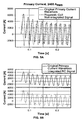
- FIG. 11A is an example waveform graph of a processed coil signal according to the present invention versus primary transformer current in an asymmetrical current fault condition.
- FIG. 11B is an example waveform graph of a pre-processed coil signal according to the present invention versus primary transformer current in an asymmetrical current fault condition.
- FIG. 11C is an example current root mean square current graph of a processed coil signal according to the present invention versus primary transformer current in an asymmetrical current fault condition.
- FIG. 11D is an example phase angle difference graph of a processed coil signal according to the present invention versus primary transformer current in an asymmetrical current fault condition.
- FIG. 12A is an example waveform graph of a transformer inrush current versus a processed coil signal according to the present invention.
- FIG. 12B is an example waveform graph of a pre-processed coil signal according to the present invention versus transformer inrush current.
- FIG. 12C is digitally shifted coil waveform according to the present invention versus transformer inrush current.
- FIG. 12D is an example root mean square current graph of a processed signal according to the present invention versus transformer inrush current.
- FIG. 12E is a root mean square current graph of a fundamental harmonic of the processed coil signal according to the present invention versus a fundamental harmonic of the transformer inrush current.
- FIG. 12F is a phase angle difference graph of fundamental harmonics of the processed coil signal according to the present invention and the transformer inrush current.
- FIG. 12G is a root mean square current graph of a second harmonics of the processed coil signal according to the present invention and the transformer inrush current.
- FIG. 12H is a phase angle difference graph of second harmonics of the processed coil signal according to the present invention and the transformer inrush current.
- Microprocessor based equipment such as digital relay devices
- complex signal processing issues are raised, especially for phasor based relay systems, to provide input data to the relay devices for making control decisions.
- CTs current transformers
- the transformers may be connected to network protection devices, such as protective relays and circuit breakers, and signal outputs from the current transformers are input to the protective devices and are used to make control decisions by the network protection devices to open circuitry when fault conditions are detected, thereby protecting the power distribution network and associated equipment from damage.
- the output signals of the transformers are vulnerable to distortion, and when used with digital equipment, such as modern digital relay devices, complex signal processing is required to convert the transformer output signals to a usable form that may be processed by the digital equipment to make control decisions.
- Rogowski coils measure magnetic fields and provide a reliable means of sensing or measuring current flow at a given point in an electrical system, including detection of current flow through a primary winding of a transformer.
- Early Rogowski coils were not suitable for such current measurements because the coil output voltage and power were not sufficient to drive measuring equipment. With the advent of microprocessor-based protection and measurement equipment, however, Rogowski coils have become more suitable for use in electrical power systems. Signal processing issues, however, still remain to interface analog output signals of Rogowski coils to digital equipment for making control decisions. Complex analog or digital filters are typically required to determine the integral of the output signal of Rogowski coils over time, increasing the cost of such systems and introducing potential errors and reliability issues.
- embodiments of protective relay devices, systems and methods are disclosed utilizing Rogowski coils as current detecting elements.
- Output signals of the Rogowski coils are used to represent current flow through a conductor in the frequency domain without determining integrals of the coil signals in the time domain that is common to known systems.
- Complex analog or digital filters in the time domain are therefore not required in embodiments of the present invention, while still providing an accurate indication of true current conditions in the conductor.
- a simpler, yet highly reliable, protective relay device, systems and methods are therefore provided.
- a protective relay system 100 includes a Rogowski coil 102 , a protective relay device 104 , an optional processing device 106 , and a circuit protector device 108 .
- the relay device 104 and or the processing device 106 are processor based devices that may be programmed to perform signal processing from the output of the Rogowski coil 100 according to the methods and algorithms explained below.
- the relay device 104 is operatively connected to a circuit protector device 108 , and depending upon the output signal v(t) of the Rogowski soil coil 102 , the relay device 104 causes the circuit protector device 108 to open or interrupt a current path when fault currents are detected.
- the Rogowski coil 102 includes a conductive coil or winding 110 , fabricated from wire in one example, that is coiled or wound on a non-magnetic core 112 for a number of turns.
- the core 112 may be formed into a toroid shape, for example, as shown in FIG. 1 , that defines a central opening 114 for the passage of a conductor 116 (shown in phantom in FIG. 1 ) therethrough.
- the Rogowski coil 102 may include different windings 110 connected in the electrically opposite directions on the core 112 .
- the opposing windings 110 will accordingly cancel all electromagnetic fields coming from outside the coil loop.
- a similar effect may be accomplished by passing the end of a single windings 110 back through the core opening 114 .
- the core 112 may be fabricated from a flexible material such as coaxial cables, or relatively rigid materials such as straight rods connected to one another at their ends.
- metering accuracy Rogowski coils may utilize printed circuit boards (PCBs) containing two imprinted coils wound in opposite directions (clockwise and counter-clockwise). This may be achieved by imprinting two windings on one PCB or using two PCBs located next to each other, each containing one imprinted winding.
- the PCBs may be multi-layered, and high precision is possible with computer controlled manufacturing process and control of the coil geometry.
- the Rogowski coil 102 may be constructed with circular, oval, and rectangular shapes, for example, in different embodiments for different applications. Rogowski coils fabricated in oval or rectangular shapes are suitable, for example, to embrace all three-phases of a conductor 116 (for measurement of residual currents) or to embrace parallel conductors 116 that carry heavy currents. As those in the art will appreciate, the Rogowski coil 102 may also be fabricated with a split-core for installation to the conductor 116 without the need to electrically disconnect the conductor 116 from the circuit.
- the Rogowski coil 102 may be placed around one or more conductors 116 whose currents i(t) are to be sensed or measured.
- a primary current i p (t) flowing through the conductor(s) 116 generates a magnetic field that, in turn, induces a secondary voltage v(t) in the windings 110 of the Rogowski coil 102 as further explained below.
- the voltage output of the Rogowski coil 102 may be connected and input to the relay 104 via wireless communication, electrical wires or cables, fiber-optic cables, or in another manner known in the art.
- the relay 104 may be programmed to perform the signal processing techniques described below while avoiding the complexity of known signal processing techniques in conventional systems.
- the protective relay device 104 may include a microprocessor 120 , an interface panel 122 , a display 124 , a memory 126 , and a communications module 128 . Control algorithms, parameters, and data may be stored in the microprocessor 120 and the memory 126 and utilized by the microprocessor 120 to execute the algorithms, respond to user inputs via the interface 122 , display information to users via the display 124 , collect and store data in the memory 126 , and communicate with other devices and systems, including but not limited to other protective relay devices.
- the relay device 104 may include various measuring and/or calculation devices (not shown) such as a voltage-measuring devices or current-calculating devices. Such devices may include, or be associated with, computer hardware or software for performing their respective functions.
- the relay device 104 may be programmed in a known manner to detect overcurrent and undercurrent conditions, overvoltage and undervoltage conditions, voltage and current differentials, and conduct frequency analysis, power analysis, load shedding analysis and power signal analysis. Additionally, the relay device 104 may also perform event recording routines for data collection and analysis, signal synchronization procedures, and conduct equipment protection routines for specific devices (e.g., motors, transformers, generators, and capacitors). Suitable relay devices 104 for purposes of the present invention include the Edison® IdeaTM of protective relays available from Cooper Power Systems, Inc. of Waukesha, Wis.
- the system 100 includes a second microprocessor based device 106 , separately provided from the relay device 104 , having a microprocessor 130 and a memory 132 .
- the voltage output v(t) of the coil 102 may be input to the second device 106 to perform the signal processing algorithms explained below, and also to extract and analyze data stored in the relay memory 126 .
- the second device 106 may optionally include an interface, display, and communications module for advanced functionality and user interaction as desired.
- the second device 106 may be, for example, another relay device, a laptop computer, a desktop computer or a workstation, or other electronic device having signal input, output and processing capabilities.
- the protective device 108 is operatively connected to the relay 104 and is responsive thereto.
- the protective device 108 may be a circuit breaker, interrupter, switching element, or other circuit protection element for interrupting the measured current i(t) in the conductor 116 when fault conditions are detected, thereby preventing damage to equipment associated with the conductor 116 .
- FIG. 2 illustrates an equivalent circuit of a conventional iron-core current transformer (CT) that is commonly found in existing medium and high voltage electrical systems.
- CT iron-core current transformer
- the CT impedance Z b sometimes referred to as the CT burden, has a low value and the secondary current i s of the transformer is nearly in phase with the primary current i p
- the secondary current i s may be distorted if the CT saturates. If the secondary current i s is being used for measurement purposes, distortion of the secondary current i s may compromise proper operation of a protective device associated with the CT.
- FIG. 3 illustrates an equivalent circuit of the Rogowski coil 102 shown in FIG. 1 .
- the burden Z b of the Rogowski coil 102 has a high value so the coil output voltage V g is shifted in phase nearly 90° relative to the measured current i p and is proportional to the rate of change of measured current (di/dt) enclosed by the coil.
- the Rogowski coil magnetizing branch is linear and the Rogowski coil secondary signal i s is not distorted.
- Comparison of CT and Rogowski coil voltage/current characteristics is shown in FIG. 4 , demonstrating the linearity of the Rogowski coil 102 and the non-linearity of the CT. Because of the linearity of the Rogowski coil 102 and its lower susceptibility to signal distortion, the Rogowski coil 102 is generally preferable to CTs for measurement and protection purposes.
- Equation 1 the voltage v(t) induced in the windings 110 of the Rogowski coil 102 is governed by the following Equation:
- Equation (1) For an ideal Rogowski coil 102 , M is independent of the location of the conductor 116 within the opening 114 . As is evident from Equation 1, the Rogowski coil output voltage v(t) is proportional to the rate of change of the measured current i(t). To obtain signals proportional to the measured current i(t), the integral of the output voltage v(t) of the Rogowski coil 100 may be mathematically computed or otherwise determined, referred to herein as integration of the voltage signal, in a known manner. Conventionally, such integration may be performed, for example, at a location remote from the coil 102 (using known analog circuitry or digital signal processing techniques) or immediately at the coil location with an integrating circuit or other device. In a conventional protective relay system, integration of Equation (1) is represented by the following relationship:
- v ⁇ ( t ) M RiCi ⁇ i ⁇ ( t ) , where R i and C i in Equation 2 represent an integrating resistor and capacitor.
- the coil output voltage v(t) will have a root mean square (RMS) value defined by Equation 3 and a phase shift nearly 90° versus the measured current i(t).
- RMS root mean square
- FIG. 5 a shows Rogowski coil output signals before and after integration of the output signals.
- the integrated and non-integrated signals are noticeably different.
- FIG. 5 b illustrates that the integrated signal accurately reproduces the waveform of the measured current in the conductor 116 (indicated as original primary current waveform in FIG. 5 b ) recorded by a laboratory current sensor, and for this reason the integrated signal has been adopted and conventionally utilized in protective relay systems.
- FIG. 6 is a block diagram of a data acquisition system 150 illustrating an analog signal flow from a conventional current transformer 152 into a conventional digital protective relay
- the system 150 includes a dielectric isolation element 154 , an anti-alias filtering element 156 , and an analog-to-digital converter 158 .
- raw sample data is available to the relay logic.
- phasor-based protective relays require further signal processing to extract the power frequency signal in the form of a complex phasor having root mean square magnitude and phase angle to adequately represent the original signal (primary current i p ).
- the Rogowski coil output signal v(t) is a scaled time derivative di/dt of the primary current i p .
- One method commonly used to obtain the fundamental complex phasor value is to apply a discrete transform 160 to the raw sample data stream.
- this transform represents a complete family of mathematical transforms there are multiple possible specific implementations which yield acceptable complex phasor outputs.
- power system events are also common to represent power system events as time-based oscillography, along with the corresponding actions determined by the logic (event recording).
- Such oscillography commonly utilizes the raw samples of the input signals, as well as the digitally filtered fundamental waveforms.
- the analog signal input to the sampling system is a linear scaled function of the original signal such as primary current i(t) measured by a current transformer
- a magnitude correction 162 as a scalar multiplier to the resultant complex phasor.
- This magnitude correction may be performed to compensate for the scalar transformations between the original signal and the numerical output of the discrete transform.
- the resultant re-scaled complex phasor may be represented within the protective relay software in preferentially advantageous units.
- FIG. 7 a block diagram of a data acquisition system 170 according to the present invention is shown in FIG. 7 .
- the system of FIG. 7 does not utilize integration of the raw sample data stream, but rather provides a non-integrated Rogowski coil output signal that is used to determine the primary current flow i p in a conductor 116 ( FIG. 1 ) that is detected by the Rogowski coil 102 .
- a simpler yet highly reliable system is therefore provided.
- FIG. 7 illustrates an analog signal flow from the Rogowski coil 102 into the protective relay device 104 .
- the system 170 includes a dielectric isolation element 172 , an anti-alias filtering element 174 , and an analog-to-digital converter 176 .
- the raw data stream for the output voltage of the Rogowski coil 102 is digitized.
- the present invention utilizes signal processing in the frequency domain without integration of the signal. That is, in the system 170 , signal processing and corrections for both the magnitude and phase angle of the Rogowski coil output signal that are frequency dependent is performed. Theory of the frequency domain will now be explained.
- Equation 1 The Rogowski coil output voltage with respect to the primary current is given by Equation 1, which can also be represented as follows.
- V(j ⁇ n ) - V ⁇ ( j ⁇ ) j ⁇ ⁇ ⁇ M ( 5 )
- the complex number V(j ⁇ n ) is the output of the discrete cosine transform for the frequency of interest, ⁇ n .
- the formula for calculating the primary current reduces to Equation 6:
- the scalar M of the Rogowski coil 102 may be advantageously determined at the fundamental power frequency, e.g. 60 Hz, and once the value of M is known, it may be used as a scalar multiplier to the voltage signal to determine the current according to Equation 6.
- the harmonic order n into Equation 6 as given by Equation 7:
- Equations 6 and 7 show that the Rogowski coil secondary signal is a voltage proportional to the primary current shifted 90°.
- the Rogowski coil secondary signal phase shift and scalar magnitude correction in the frequency domain may be utilized for making control decisions.
- processing techniques in the frequency domain rather than in the time domain as conventionally employed, complex analog or digital filters in the time domain needed to integrate the signal are avoided, together with associated expense.
- reduced processing demands are experienced in the relay 104 and/or the external device 106 ( FIG. 1 ). Faster computing times are therefore possible in comparison to known systems.
- Equation 8a The signal flow chart of FIG. 7 is summarized by Equations 8a and 8b.
- i p (t) in the conductor 116 passing through the Rogowski coil 102 is represented in the frequency domain as I ⁇ translated by the Rogowski coil to v(t), which is a scaled time derivative of i p (t).
- the output signal v(t) of the coil 102 is digitized and processed through a known discrete transform algorithm, such as a Fourier Transform in one example, to determine the complex number representation of its one or more constituent frequency components.
- the one or more frequency components of interest represented by the complex number output of the discrete transform algorithm 178 , are then modified by scalar multiplication and 90° phase shift 180 to obtain frequency domain representations of the original measured current i p (t).
- i p (t) may correspond to a sensed current in a primary winding of a current transformer, although other applications are contemplated as well.
- event recording can provide true representation of the primary current waveform I(t).
- oscillographic recordings may provide the di/dt signals, but not readily utilized I(t) signals of the primary current.
- the di/dt raw sample data may be stored in the relay memory 126 ( FIG. 1 ), and event recording viewing may be performed offline at a location remote from the relay device 104 with another device 106 ( FIG. 1 ). Integration functions 182 on the raw sample data may also be run offline as desired to extract I(t) waveforms without burdening the relay device 104 with integration of the signal and necessary computations.
- Event recording software may be provided that includes integration of the Rogowski coil non-integrated signals as well as additional algorithms for final analysis, which may be run offline.
- the relay 104 may make control decisions based upon non-integrated signals from the Rogowski coil 102 . Specifically, based upon the phasor data obtained from the non-integrated Rogowski coil signal, a true representation of the current flow in the conductor 116 ( FIG. 1 ) may be provided. Once the representation of the current flow is obtained, the relay may identify fault conditions 182 in the conductor 116 ( FIG. 1 ) being monitored with the Rogowski coil 102 in a known manner. When fault conditions are identified, the relay device 104 may take appropriate corrective and protective action 184 , such as communicating with other devices and systems via the communications module 128 ( FIG. 1 ) and causing the protective device 108 ( FIG. 1 ) to interrupt the current path being monitored with the Rogowski coil 102 to protect associated equipment from damage.
- the data acquisition system 170 may be implemented using conventional programming techniques that are within the purview of those in the art. Further explanation of associated algorithms, methods and techniques associated with such programming is not believed to be necessary. Such programs, methods and techniques may be executable by the microprocessor based relay device 104 and/or the secondary device 106 .
- FIG. 8A illustrates a symmetrical primary current and the Rogowski coil secondary signal shifted 90° compared to the primary current.
- Calculated RMS values for primary current and the RC secondary signal scaled to the primary are nearly identical after one cycle needed for phasor estimation algorithm to reach full accuracy ( FIG. 8B ).
- the Rogowski coil phase angle of the secondary signal is digitally shifted 90°, the phase angle difference between the primary current and the Rogowski coil secondary signal becomes nearly zero ( FIG. 8C ).
- FIG. 9A shows primary current and the Rogowski coil secondary signal for asymmetrical current faults.
- the Rogowski coil secondary signal waveform differs from the primary current waveform since the DC component is attenuated and the signal is also shifted 90°
- calculated RMS values for primary current and the Rogowski coil secondary signal scaled to the primary become nearly identical after DC component attenuates in the primary current ( FIG. 9B ).
- the phase angle difference between the primary current and the Rogowski coil secondary signal digitally shifted 90° becomes nearly zero ( FIG. 9 c ).
- FIGS. 10A and 10B show primary current and the Rogowski coil secondary signal during a transformer energizing.
- the Rogowski coil secondary signal waveform differs from the primary current waveform since the primary current contains a large percent of the second harmonic component.
- calculated RMS values for primary current and the Rogowski coil secondary signal scaled to the primary become nearly identical ( FIG. 10C ).
- the phase angle difference between the primary current and the Rogowski coil secondary signal digitally shifted 90° is nearly zero ( FIG. 10D ).
- the second harmonic component is pronounced and may be used for blocking the protection operation.
- FIGS. 10E and 10F show that both the amplitude and phase angle of the second harmonic component can be reliably calculated, and both the primary current and the Rogowski coil secondary signal are nearly identical.
- FIG. 11A shows primary current and the Rogowski coil secondary signal for asymmetrical current faults sampled at 16 samples per cycle in a protective relay system such as that shown in FIG. 1 .
- the DC component of the primary current has been filtered by the relay consistently with FIG. 7 .
- the Rogowski coil secondary signal waveform (before it was shifted 90°) and the primary current waveform are shown in FIG. 11B .
- Calculated RMS values for primary current and the Rogowski coil secondary signal scaled to the primary are nearly identical ( FIG. 11C ).
- the phase angle difference between the primary current and the Rogowski coil secondary signal digitally shifted 90° becomes nearly zero ( FIG. 11D ).
- FIG. 12A shows primary current and the Rogowski coil secondary signal during a transformer energizing sampled at 16 samples per cycle in a protective relay system such as that shown in FIG. 1 .
- the DC component of the primary current has been filtered by the relay consistently with the system of FIG. 7 .
- the Rogowski coil secondary signal waveform (before it was shifted 90°) and the primary current waveform are shown in FIG. 12B ).
- the phase angle difference between the primary current and the Rogowski coil secondary signal digitally shifted 90° becomes nearly zero ( FIG. 12C ).
- Calculated RMS values of all components for primary current and the Rogowski coil secondary signal scaled to the primary are nearly identical ( FIG. 12D ).
- Embodiments of protective relay systems including Rogowski coils and signal processing techniques therefore are disclosed herein.
- Advantages of the invention include a simplified, yet highly effective and reliable, signal processing scheme wherein accurate representations of current flow may be provided at lower cost and in less time than conventional systems using more complex signal processing techniques and involving greater computational demands.
- An embodiment of a protective system for a current path in a in an electrical power system comprises a Rogowski coil generating an output voltage signal corresponding to current flow in the current path; and a microprocessor based protection device receiving the output voltage signal.
- the microprocessor based protection device is responsive to the output voltage signal to cause the current path to be interrupted when a fault condition is detected, wherein the fault condition is detected without integration of the output voltage signal in the time domain.
- the voltage output signal may be processed in the frequency domain, and the phase of voltage output signal is digitally shifted by approximately 90 degrees
- the voltage output signal may further be multiplied by a scalar.
- the microprocessor based device may comprise a digital relay device, and the relay device may be configured to detect the fault condition.
- a second microprocessor based device may be separately provided from the protective device, and the second microprocessor based device may be configured to detect the fault condition, and may also be configured to integrate the voltage output signal to extract power analysis information.
- a circuit protector may be operatively connected to the protective device, with the protective device causing the circuit protector to open the current path in response to the output voltage signal.
- the system comprises a Rogowski coil generating an output voltage signal proportional to a time derivative of a current flow in the current path, and a microprocessor based relay device receiving a non-integrated output voltage signal of the Rogowski coil.
- the relay device causes the current path to be interrupted when a fault condition is detected using the non-integrated output voltage signal.
- the fault condition is detected without integration of the output voltage signal in the time domain.
- the voltage output signal may be processed in the frequency domain.
- the phase of the non-integrated voltage output signal may be digitally shifted by approximately 90 degrees, and the voltage output signal may be multiplied by a scalar.
- the relay may comprise a microprocessor and a memory, with the microprocessor and memory configured to detect the fault condition.
- a second microprocessor based device may be separately provided from the relay device, and the second microprocessor based device may process the non-integrated output voltage signal.
- a circuit protector may be operatively connected to the relay device, with the relay device causing the circuit protector to open the current path in response to the output voltage signal.
- the system comprises a conductor defining a current path in the electrical system, a Rogowski coil receiving the conductor and generating an analog output voltage signal proportional to a time derivative of current flow in the current path, and a digital relay device receiving the analog output voltage signal.
- the relay device is configured to digitize the signal and process the signal in the frequency domain to represent the current flow without integration of the output voltage signal in the time domain.
- the relay device causes the current path to be interrupted when a fault condition is detected using the represented current flow.
- the phase of the non-integrated voltage output signal may be digitally shifted by approximately 90 degrees, and the voltage output signal may be multiplied by a scalar.
- the relay may comprise a microprocessor and a memory, with the microprocessor and memory configured to detect the fault condition.
- a circuit protector may be operatively connected to the relay device, with the relay device causing the circuit protector to open the current path in response to the output voltage signal.
- a digital relay device responsive to an output voltage signal of a Rogowski coil.
- the relay device comprises a processor and a memory, wherein the processor and memory are configured to execute a control algorithm whereby the output voltage signal is processed in the frequency domain without integration of the output voltage signal in the time domain to determine a current signal corresponding to the output voltage signal.
- the processor and memory are further configured to detect a fault condition using the determined current signal.
- a circuit protector may be provided, with the relay causing the circuit protector to open a circuit path when the fault condition is detected.
- the output voltage signal may be multiplied by a scalar to determine the current signal, and the phase of the output voltage signal may be digitally shifted to determine the current signal.
- the output voltage of the Rogowski coil may be an analog signal, and the relay may comprise an analog to digital converter to digitize the output voltage signal.
- a method of processing an output voltage signal of a Rogowski coil for control of a current path with a protective relay device comprises obtaining the output voltage signal; digitizing the output signal; and determining a current signal corresponding the output voltage signal without integration of the output voltage signal in the time domain.
- determining the current signal may comprise applying a discrete transform algorithm to the digitized output signal, digitally shifting the phase of the digitized output signal, and multiplying the digitized signal by a scalar.
- the method may further comprise comparing the determined signal to a predetermined fault current signal, and detecting a fault condition based upon the compared determined signal and fault current signal.
- the method may also comprise causing a circuit protector to interrupt a current path extending through the Rogowski coil.
- the method may comprise storing in the relay device data relating to the determined current over time, extracting the data from the relay device, and integrating the extracted data with a microprocessor based device separate from the relay device.
- An embodiment of a protective system for an electrical network comprises a Rogowski coil monitoring a current path in an electrical system, and means for processing an output voltage signal of the Rogowski coil to provide a current signal corresponding to a time derivative of current flow in the current path.
- the means for processing provides the current signal while avoiding integration in the time domain of the output voltage signal.
- the means for processing may comprise a digital relay device.
- the system may also include means for interrupting the current flow in the current path when the provided current signal corresponds to a fault condition, means for storing data relating to the provided current signal over time, and means for extracting the stored data and analyzing the data.
Abstract
Description
where μo is the magnetic permeability of free space, μr is the relative permeability (the ratio of the permeability of the
where Ri and Ci in Equation 2 represent an integrating resistor and capacitor.
V rms =Mω√{square root over (2)}Irms
V(s)=−sMI(s) (4a).
Recognizing that s is the Laplace operator jω in the frequency domain then Equation 4a may further be rewritten as
V(jω)=−jωMI(jω) (4b).
The complex number V(jωn) is the output of the discrete cosine transform for the frequency of interest, ωn. When represented in single-frequency phasor form, the formula for calculating the primary current reduces to Equation 6:
Briefly, the measured primary current ip(t) (shown in
Claims (13)
Priority Applications (1)
| Application Number | Priority Date | Filing Date | Title |
|---|---|---|---|
| US12/566,279 US7902813B2 (en) | 2006-04-07 | 2009-09-24 | Protective digital relay device |
Applications Claiming Priority (2)
| Application Number | Priority Date | Filing Date | Title |
|---|---|---|---|
| US11/400,087 US7638999B2 (en) | 2006-04-07 | 2006-04-07 | Protective relay device, system and methods for Rogowski coil sensors |
| US12/566,279 US7902813B2 (en) | 2006-04-07 | 2009-09-24 | Protective digital relay device |
Related Parent Applications (1)
| Application Number | Title | Priority Date | Filing Date |
|---|---|---|---|
| US11/400,087 Division US7638999B2 (en) | 2006-04-07 | 2006-04-07 | Protective relay device, system and methods for Rogowski coil sensors |
Publications (2)
| Publication Number | Publication Date |
|---|---|
| US20100020457A1 US20100020457A1 (en) | 2010-01-28 |
| US7902813B2 true US7902813B2 (en) | 2011-03-08 |
Family
ID=38574561
Family Applications (2)
| Application Number | Title | Priority Date | Filing Date |
|---|---|---|---|
| US11/400,087 Active 2026-08-18 US7638999B2 (en) | 2006-04-07 | 2006-04-07 | Protective relay device, system and methods for Rogowski coil sensors |
| US12/566,279 Active US7902813B2 (en) | 2006-04-07 | 2009-09-24 | Protective digital relay device |
Family Applications Before (1)
| Application Number | Title | Priority Date | Filing Date |
|---|---|---|---|
| US11/400,087 Active 2026-08-18 US7638999B2 (en) | 2006-04-07 | 2006-04-07 | Protective relay device, system and methods for Rogowski coil sensors |
Country Status (1)
| Country | Link |
|---|---|
| US (2) | US7638999B2 (en) |
Cited By (10)
| Publication number | Priority date | Publication date | Assignee | Title |
|---|---|---|---|---|
| US20100312505A1 (en) * | 2007-10-30 | 2010-12-09 | Frank Berger | Short-circuit recognition method for an electric network |
| US20110115466A1 (en) * | 2006-03-31 | 2011-05-19 | Daihen Corporation | Current detection printed board, voltage detection printed board, current/voltage detection printed board, current/voltage detector, current detector and voltage detector |
| US20120143535A1 (en) * | 2010-06-23 | 2012-06-07 | Hiroyuki Maehara | Substation instrument control system |
| US20150243360A1 (en) * | 2014-02-26 | 2015-08-27 | Infineon Technologies Ag | Method, apparatus and device for data processing |
| US9805771B2 (en) | 2014-02-26 | 2017-10-31 | Infineon Technologies Ag | Determining a state of a cell structure |
| US9921243B2 (en) | 2012-12-17 | 2018-03-20 | Covidien Lp | System and method for voltage and current sensing |
| US10281496B2 (en) | 2014-12-02 | 2019-05-07 | Covidien Lp | Electrosurgical generators and sensors |
| US10278764B2 (en) | 2014-12-02 | 2019-05-07 | Covidien Lp | Electrosurgical generators and sensors |
| US10292753B2 (en) | 2014-12-02 | 2019-05-21 | Covidien Lp | Electrosurgical generators and sensors |
| US11435409B2 (en) * | 2018-01-09 | 2022-09-06 | Rensselaer Polytechnic Institute | Temporary overvoltage and ground fault overvoltage protection based on arrester current measurement and analysis |
Families Citing this family (36)
| Publication number | Priority date | Publication date | Assignee | Title |
|---|---|---|---|---|
| US7003435B2 (en) | 2002-10-03 | 2006-02-21 | Leviton Manufacturing Co., Inc. | Arc fault detector with circuit interrupter |
| GB0409549D0 (en) * | 2004-04-29 | 2004-06-02 | Lem Heme Ltd | Current measurement apparatus |
| CN100439926C (en) * | 2006-03-31 | 2008-12-03 | 北京万工科技有限公司 | Integrator for Rogowski coil and its realizing method |
| US7638999B2 (en) | 2006-04-07 | 2009-12-29 | Cooper Technologies Company | Protective relay device, system and methods for Rogowski coil sensors |
| US7564233B2 (en) * | 2006-11-06 | 2009-07-21 | Cooper Technologies Company | Shielded Rogowski coil assembly and methods |
| WO2009063118A1 (en) * | 2007-11-14 | 2009-05-22 | Universitat Politècnica De Catalunya | System for diagnosing defects in electric motors |
| ES2340123B1 (en) * | 2008-07-04 | 2011-04-04 | Universitat Politècnica De Catalunya | MEASUREMENT SYSTEM WITH ROGOWSKI PROBE WITHOUT INTEGRATOR. |
| US7738221B2 (en) * | 2007-12-07 | 2010-06-15 | Cooper Technologies Company | Transformer inrush current detector |
| CN101910856B (en) | 2008-01-29 | 2014-06-18 | 立维腾制造有限公司 | Self testing fault circuit interrupter apparatus and method |
| DE102008043103A1 (en) * | 2008-10-22 | 2010-04-29 | Alstrom Technology Ltd. | Apparatus and method for monitoring and / or analyzing rotors of electric machines in operation |
| US8193818B2 (en) * | 2009-01-15 | 2012-06-05 | Hamilton Sundstrand Corporation | Partial corona discharge detection |
| GB0913571D0 (en) * | 2009-08-04 | 2009-09-16 | Ea Tech Ltd | Current detector |
| US8203814B2 (en) * | 2009-08-31 | 2012-06-19 | Eaton Corporation | Electrical switching apparatus including a plurality of Rogowski coils and method of calibrating the same |
| US8264215B1 (en) * | 2009-12-10 | 2012-09-11 | The Boeing Company | Onboard electrical current sensing system |
| JP5290228B2 (en) * | 2010-03-30 | 2013-09-18 | 株式会社日本自動車部品総合研究所 | Voltage detector, abnormality detection device, contactless power transmission device, contactless power receiving device, contactless power feeding system, and vehicle |
| US20120026630A1 (en) * | 2010-07-30 | 2012-02-02 | Sutherland Peter E | Method and Apparatus For Use In Monitoring Operation of Electrical Switchgear |
| US10390740B2 (en) | 2010-12-29 | 2019-08-27 | Medtronic Minimed, Inc. | Glycemic health metric determination and application |
| US8681469B2 (en) | 2011-03-22 | 2014-03-25 | General Electric Company | Circuit protection device for use in medium and high voltage environments |
| JP5820164B2 (en) * | 2011-07-01 | 2015-11-24 | 東光東芝メーターシステムズ株式会社 | Current detection device and watt-hour meter using the same |
| US8599523B1 (en) | 2011-07-29 | 2013-12-03 | Leviton Manufacturing Company, Inc. | Arc fault circuit interrupter |
| CN102435827A (en) * | 2011-09-15 | 2012-05-02 | 西安交通大学 | Rogowski coil-based method and Rogowski coil-based device for detecting direct-current short-circuit current fault |
| CN102878917B (en) * | 2012-09-17 | 2014-11-12 | 华中科技大学 | Signal operation device based on Rogowski coil measurement |
| US8830645B2 (en) * | 2013-01-11 | 2014-09-09 | Cooper Technologies Company | Power spike mitigation |
| US20140198420A1 (en) * | 2013-01-11 | 2014-07-17 | Cooper Technologies Company | Fault-Likely Detector |
| US9408298B2 (en) | 2014-03-18 | 2016-08-02 | Eaton Corporation | Flexible circuit Rogowski coil |
| US9759758B2 (en) | 2014-04-25 | 2017-09-12 | Leviton Manufacturing Co., Inc. | Ground fault detector |
| US9606146B2 (en) * | 2014-09-25 | 2017-03-28 | Fluke Corporation | Wireless rogowski coil system |
| US10274522B2 (en) * | 2015-09-02 | 2019-04-30 | Veris Industries, Llc | Mobile device coupled Rogowski coil |
| US10545177B2 (en) * | 2015-09-02 | 2020-01-28 | Veris Industries, Llc | Non-contact sensor based Rogowski coil |
| CN106019072B (en) * | 2016-05-13 | 2018-09-11 | 国网四川省电力公司电力科学研究院 | The measurement method of Rogowski coil lumped parameter |
| CN107395172B (en) * | 2017-07-26 | 2020-05-05 | 广州市精源电子设备有限公司 | Analog switch circuit and inverter resistance welder secondary current detection system |
| EP4152539A1 (en) * | 2018-09-27 | 2023-03-22 | Siemens Aktiengesellschaft | Arrangement and method for a low voltage alternating current circuit |
| CN111257609B (en) * | 2020-01-09 | 2022-08-12 | 平高集团有限公司 | Tunneling magnetoresistance-based current sensor and parameter determination method thereof |
| FR3108986B1 (en) * | 2020-04-02 | 2022-04-15 | Safran Electrical & Power | Very wide bandwidth current sensor |
| CN111987698B (en) * | 2020-07-30 | 2022-10-04 | 许继集团有限公司 | Differential current differential protection method for different types of current transformer mixed lines |
| US11852692B1 (en) * | 2022-12-09 | 2023-12-26 | Milo Group Llc | Electric distribution line ground fault prevention systems using dual parameter monitoring with high sensitivity relay devices |
Citations (50)
| Publication number | Priority date | Publication date | Assignee | Title |
|---|---|---|---|---|
| GB1355827A (en) | 1970-12-17 | 1974-06-05 | Merlin Gerin | Electrical power distribution system |
| US4039930A (en) | 1976-08-12 | 1977-08-02 | General Electric Company | Remotely controlled phase shifting circuit |
| US4063166A (en) | 1975-06-05 | 1977-12-13 | Bbc Brown Boveri & Company Limited | Method for locating a fault on a line near to a measuring location with the aid of substitute signals |
| US4446420A (en) | 1982-01-28 | 1984-05-01 | Hydro Quebec | Method and device for detecting and locating fault and/or partial discharges in a gas-insulated electrical equipment |
| US4449417A (en) | 1981-03-16 | 1984-05-22 | Oki Electric Industry Co., Ltd. | Carrier moving mechanism |
| US4570231A (en) | 1984-01-27 | 1986-02-11 | Richard H. Bunch | Fault finder |
| US4623949A (en) | 1985-09-06 | 1986-11-18 | Westinghouse Electric Corp. | Bus differential relay |
| US4709339A (en) | 1983-04-13 | 1987-11-24 | Fernandes Roosevelt A | Electrical power line parameter measurement apparatus and systems, including compact, line-mounted modules |
| US4709205A (en) | 1985-06-28 | 1987-11-24 | La Telemecanique Electrique | Inductive sensor for current measurement |
| US4749940A (en) | 1986-12-22 | 1988-06-07 | General Electric Company | Folded bar current sensor |
| US4766549A (en) | 1984-11-30 | 1988-08-23 | Electric Power Research Institute, Inc. | Single-ended transmission line fault locator |
| US4933630A (en) | 1988-07-26 | 1990-06-12 | Gec Alsthom Sa | System for measuring phase currents in a 3-phase installation |
| US4939449A (en) | 1986-12-12 | 1990-07-03 | Liaisons Electroniques-Mecaniques Lem Sa | Electric current sensing device of the magnetic field compensation type |
| US5115447A (en) | 1991-01-10 | 1992-05-19 | Ucar Carbon Technology Corporation | Arc furnace electrode control |
| US5128611A (en) | 1989-03-07 | 1992-07-07 | Zellweger Uster Ag | Electronic electricity meter |
| US5414400A (en) | 1992-06-05 | 1995-05-09 | Gec Alsthom T&D Sa | Rogowski coil |
| US5434509A (en) | 1992-07-30 | 1995-07-18 | Blades; Frederick K. | Method and apparatus for detecting arcing in alternating-current power systems by monitoring high-frequency noise |
| US5442280A (en) | 1992-09-10 | 1995-08-15 | Gec Alstom T & D Sa | Device for measuring an electrical current in a conductor using a Rogowski coil |
| US5608327A (en) | 1994-04-25 | 1997-03-04 | Gec Alsthom Limited | Methods and apparatus for identifying faulted phases on an electric power transmission line |
| US5825189A (en) | 1994-01-26 | 1998-10-20 | Gec Alsthom Limited | Method of locating the position of a fault on a power transmission |
| US5825395A (en) | 1994-10-12 | 1998-10-20 | Fuji Photo Film Co., Ltd. | Thermal head |
| US5903155A (en) | 1996-08-29 | 1999-05-11 | Asea Brown Boveri Ab | Method of measurement for fault-distance determination on a HVDC power transmission line having at least two lines connected in parallel |
| US6313623B1 (en) | 2000-02-03 | 2001-11-06 | Mcgraw-Edison Company | High precision rogowski coil |
| US6397156B1 (en) | 1998-11-17 | 2002-05-28 | Abb Inc. | Impedance measurement system for power system transmission lines |
| US6544314B2 (en) | 2000-03-17 | 2003-04-08 | Specialty Minerals (Michigan) Inc. | Process and apparatus for automatically controlling slag foaming |
| US6563296B2 (en) | 1998-06-05 | 2003-05-13 | Chathan M. Cooke | Closely-coupled multiple-winding magnetic induction-type sensor |
| US6597180B1 (en) | 1998-12-28 | 2003-07-22 | Nippon Kouatsu Electric Co., Ltd. | Fault point location system |
| US6624624B1 (en) | 1999-05-25 | 2003-09-23 | Arbeitsgemeinschaft Prof. Hugel Agph | Electrical current sensor |
| US6680608B2 (en) | 2002-02-27 | 2004-01-20 | Mcgraw-Edison Company | Measuring current through an electrical conductor |
| US20040012901A1 (en) * | 2002-07-12 | 2004-01-22 | Kojovic Ljubomir A. | Electrical arc furnace protection system |
| US20040027748A1 (en) | 2002-07-12 | 2004-02-12 | Kojovic Ljubomir A. | Electrical protection system |
| US6713998B2 (en) * | 2000-11-06 | 2004-03-30 | Abb Research Ltd | Method for measuring the resistance and the inductance of a line |
| US6781361B2 (en) | 2001-04-26 | 2004-08-24 | Analog Devices, Inc. | Apparatus and system for electrical power metering using digital integration |
| US6782329B2 (en) | 1998-02-19 | 2004-08-24 | Square D Company | Detection of arcing faults using bifurcated wiring system |
| US6822457B2 (en) | 2003-03-27 | 2004-11-23 | Marshall B. Borchert | Method of precisely determining the location of a fault on an electrical transmission system |
| US6844737B2 (en) | 2001-12-06 | 2005-01-18 | Schneider Electric Industries Sas | Device and process for detecting an electrical short-circuit, and circuit breaker comprising such a device |
| US6853528B2 (en) | 2002-03-14 | 2005-02-08 | Hitachi, Ltd. | Gas insulating apparatus and method for locating fault point thereof |
| US20050122654A1 (en) * | 2003-12-08 | 2005-06-09 | Siemens Energy & Automation | Extended instantaneous protection |
| US6954704B2 (en) | 2002-08-06 | 2005-10-11 | Kabushiki Kaisha Toshiba | Digital protection and control device |
| US20050248430A1 (en) | 2004-05-10 | 2005-11-10 | Areva T&D Sa | Current transformer with rogowski type windings, comprising an association of partial circuits forming a complete circuit |
| US20060012374A1 (en) | 2004-07-15 | 2006-01-19 | Kojovic Ljubomir A | Traveling wave based relay protection |
| US20060256488A1 (en) * | 2005-05-11 | 2006-11-16 | Eaton Corporation | Medium voltage motor starter including a contactor having motor protection relay functionality |
| US7174261B2 (en) | 2003-03-19 | 2007-02-06 | Power Measurement Ltd. | Power line sensors and systems incorporating same |
| US7180717B2 (en) | 2002-07-12 | 2007-02-20 | Cooper Technologies Company | Electrical network protection system |
| US7227347B2 (en) | 2002-09-12 | 2007-06-05 | Abb Services S.R.L. | Device and method for measuring a current |
| US20080154523A1 (en) | 2001-02-23 | 2008-06-26 | Power Measurement Ltd. | Intelligent Electronic Device Having Network Access |
| US7538541B2 (en) | 2006-11-06 | 2009-05-26 | Cooper Technologies Company | Split Rogowski coil current measuring device and methods |
| US7564233B2 (en) | 2006-11-06 | 2009-07-21 | Cooper Technologies Company | Shielded Rogowski coil assembly and methods |
| US7638999B2 (en) | 2006-04-07 | 2009-12-29 | Cooper Technologies Company | Protective relay device, system and methods for Rogowski coil sensors |
| US7738221B2 (en) | 2007-12-07 | 2010-06-15 | Cooper Technologies Company | Transformer inrush current detector |
Family Cites Families (6)
| Publication number | Priority date | Publication date | Assignee | Title |
|---|---|---|---|---|
| US593240A (en) * | 1897-11-09 | Forge-twyer | ||
| US593239A (en) * | 1897-11-09 | Coffin-handle | ||
| US999813A (en) * | 1909-06-21 | 1911-08-08 | North Losey | Artificial-light-diffusing apparatus. |
| US5141400A (en) * | 1991-01-25 | 1992-08-25 | General Electric Company | Wide chord fan blade |
| DE19640981A1 (en) | 1996-10-04 | 1998-04-16 | Asea Brown Boveri | Rogowski coil |
| GB9918539D0 (en) * | 1999-08-06 | 1999-10-06 | Sentec Ltd | Planar current transformer |
-
2006
- 2006-04-07 US US11/400,087 patent/US7638999B2/en active Active
-
2009
- 2009-09-24 US US12/566,279 patent/US7902813B2/en active Active
Patent Citations (58)
| Publication number | Priority date | Publication date | Assignee | Title |
|---|---|---|---|---|
| GB1355827A (en) | 1970-12-17 | 1974-06-05 | Merlin Gerin | Electrical power distribution system |
| US4063166A (en) | 1975-06-05 | 1977-12-13 | Bbc Brown Boveri & Company Limited | Method for locating a fault on a line near to a measuring location with the aid of substitute signals |
| US4039930A (en) | 1976-08-12 | 1977-08-02 | General Electric Company | Remotely controlled phase shifting circuit |
| US4449417A (en) | 1981-03-16 | 1984-05-22 | Oki Electric Industry Co., Ltd. | Carrier moving mechanism |
| US4446420A (en) | 1982-01-28 | 1984-05-01 | Hydro Quebec | Method and device for detecting and locating fault and/or partial discharges in a gas-insulated electrical equipment |
| US4709339A (en) | 1983-04-13 | 1987-11-24 | Fernandes Roosevelt A | Electrical power line parameter measurement apparatus and systems, including compact, line-mounted modules |
| US4570231A (en) | 1984-01-27 | 1986-02-11 | Richard H. Bunch | Fault finder |
| US4766549A (en) | 1984-11-30 | 1988-08-23 | Electric Power Research Institute, Inc. | Single-ended transmission line fault locator |
| US4709205A (en) | 1985-06-28 | 1987-11-24 | La Telemecanique Electrique | Inductive sensor for current measurement |
| US4623949A (en) | 1985-09-06 | 1986-11-18 | Westinghouse Electric Corp. | Bus differential relay |
| US4939449A (en) | 1986-12-12 | 1990-07-03 | Liaisons Electroniques-Mecaniques Lem Sa | Electric current sensing device of the magnetic field compensation type |
| US4749940A (en) | 1986-12-22 | 1988-06-07 | General Electric Company | Folded bar current sensor |
| US4933630A (en) | 1988-07-26 | 1990-06-12 | Gec Alsthom Sa | System for measuring phase currents in a 3-phase installation |
| US5128611A (en) | 1989-03-07 | 1992-07-07 | Zellweger Uster Ag | Electronic electricity meter |
| US5115447A (en) | 1991-01-10 | 1992-05-19 | Ucar Carbon Technology Corporation | Arc furnace electrode control |
| EP0494720A2 (en) | 1991-01-10 | 1992-07-15 | Ucar Carbon Technology Corporation | Arc furnace electrode control |
| US5414400A (en) | 1992-06-05 | 1995-05-09 | Gec Alsthom T&D Sa | Rogowski coil |
| US5434509A (en) | 1992-07-30 | 1995-07-18 | Blades; Frederick K. | Method and apparatus for detecting arcing in alternating-current power systems by monitoring high-frequency noise |
| US5461309A (en) | 1992-09-10 | 1995-10-24 | Gec Alsthom T&D Sa | Device for measuring temperature using a Rogowski coil |
| US5442280A (en) | 1992-09-10 | 1995-08-15 | Gec Alstom T & D Sa | Device for measuring an electrical current in a conductor using a Rogowski coil |
| US5825189A (en) | 1994-01-26 | 1998-10-20 | Gec Alsthom Limited | Method of locating the position of a fault on a power transmission |
| US5608327A (en) | 1994-04-25 | 1997-03-04 | Gec Alsthom Limited | Methods and apparatus for identifying faulted phases on an electric power transmission line |
| US5825395A (en) | 1994-10-12 | 1998-10-20 | Fuji Photo Film Co., Ltd. | Thermal head |
| US5903155A (en) | 1996-08-29 | 1999-05-11 | Asea Brown Boveri Ab | Method of measurement for fault-distance determination on a HVDC power transmission line having at least two lines connected in parallel |
| US6782329B2 (en) | 1998-02-19 | 2004-08-24 | Square D Company | Detection of arcing faults using bifurcated wiring system |
| US6563296B2 (en) | 1998-06-05 | 2003-05-13 | Chathan M. Cooke | Closely-coupled multiple-winding magnetic induction-type sensor |
| US6397156B1 (en) | 1998-11-17 | 2002-05-28 | Abb Inc. | Impedance measurement system for power system transmission lines |
| US6597180B1 (en) | 1998-12-28 | 2003-07-22 | Nippon Kouatsu Electric Co., Ltd. | Fault point location system |
| US6624624B1 (en) | 1999-05-25 | 2003-09-23 | Arbeitsgemeinschaft Prof. Hugel Agph | Electrical current sensor |
| US6313623B1 (en) | 2000-02-03 | 2001-11-06 | Mcgraw-Edison Company | High precision rogowski coil |
| US6544314B2 (en) | 2000-03-17 | 2003-04-08 | Specialty Minerals (Michigan) Inc. | Process and apparatus for automatically controlling slag foaming |
| US6713998B2 (en) * | 2000-11-06 | 2004-03-30 | Abb Research Ltd | Method for measuring the resistance and the inductance of a line |
| US20080154523A1 (en) | 2001-02-23 | 2008-06-26 | Power Measurement Ltd. | Intelligent Electronic Device Having Network Access |
| US7415368B2 (en) | 2001-02-23 | 2008-08-19 | Power Measurement Ltd. | Intelligent electronic device having network access |
| US6781361B2 (en) | 2001-04-26 | 2004-08-24 | Analog Devices, Inc. | Apparatus and system for electrical power metering using digital integration |
| US6844737B2 (en) | 2001-12-06 | 2005-01-18 | Schneider Electric Industries Sas | Device and process for detecting an electrical short-circuit, and circuit breaker comprising such a device |
| US6680608B2 (en) | 2002-02-27 | 2004-01-20 | Mcgraw-Edison Company | Measuring current through an electrical conductor |
| US6853528B2 (en) | 2002-03-14 | 2005-02-08 | Hitachi, Ltd. | Gas insulating apparatus and method for locating fault point thereof |
| US6940702B2 (en) | 2002-07-12 | 2005-09-06 | Mcgraw-Edison Company | Electrical protection system |
| US6810069B2 (en) | 2002-07-12 | 2004-10-26 | Mcgraw-Edison Company | Electrical arc furnace protection system |
| US20040027748A1 (en) | 2002-07-12 | 2004-02-12 | Kojovic Ljubomir A. | Electrical protection system |
| US20040012901A1 (en) * | 2002-07-12 | 2004-01-22 | Kojovic Ljubomir A. | Electrical arc furnace protection system |
| US7180717B2 (en) | 2002-07-12 | 2007-02-20 | Cooper Technologies Company | Electrical network protection system |
| US6954704B2 (en) | 2002-08-06 | 2005-10-11 | Kabushiki Kaisha Toshiba | Digital protection and control device |
| US7227347B2 (en) | 2002-09-12 | 2007-06-05 | Abb Services S.R.L. | Device and method for measuring a current |
| US7174261B2 (en) | 2003-03-19 | 2007-02-06 | Power Measurement Ltd. | Power line sensors and systems incorporating same |
| US6822457B2 (en) | 2003-03-27 | 2004-11-23 | Marshall B. Borchert | Method of precisely determining the location of a fault on an electrical transmission system |
| US20050122654A1 (en) * | 2003-12-08 | 2005-06-09 | Siemens Energy & Automation | Extended instantaneous protection |
| US20050248430A1 (en) | 2004-05-10 | 2005-11-10 | Areva T&D Sa | Current transformer with rogowski type windings, comprising an association of partial circuits forming a complete circuit |
| US7535233B2 (en) | 2004-07-15 | 2009-05-19 | Cooper Technologies Company | Traveling wave based relay protection |
| US20060012374A1 (en) | 2004-07-15 | 2006-01-19 | Kojovic Ljubomir A | Traveling wave based relay protection |
| US20090230974A1 (en) | 2004-07-15 | 2009-09-17 | Mcgraw-Edison Company | Traveling wave based relay protection |
| US20060256488A1 (en) * | 2005-05-11 | 2006-11-16 | Eaton Corporation | Medium voltage motor starter including a contactor having motor protection relay functionality |
| US7638999B2 (en) | 2006-04-07 | 2009-12-29 | Cooper Technologies Company | Protective relay device, system and methods for Rogowski coil sensors |
| US20100020457A1 (en) | 2006-04-07 | 2010-01-28 | Cooper Technologies Company | Protective Digital Relay Device |
| US7538541B2 (en) | 2006-11-06 | 2009-05-26 | Cooper Technologies Company | Split Rogowski coil current measuring device and methods |
| US7564233B2 (en) | 2006-11-06 | 2009-07-21 | Cooper Technologies Company | Shielded Rogowski coil assembly and methods |
| US7738221B2 (en) | 2007-12-07 | 2010-06-15 | Cooper Technologies Company | Transformer inrush current detector |
Non-Patent Citations (6)
| Title |
|---|
| "Contribution of Digital Signal Processing in the Field of Current Transformers", E. Thuries, 1996, pp. 1-11. |
| "Magnetischer Spannungsmesser Hoher Praazision", V. Neumann, Electrotechnische Zeitschrift Ausgabe A., May 21, 1962, Germany, pp. 349-356. |
| "Rogowski Coils Suit Relay Protection and Measurement", L. Kojovic, Jul. 1997, pp. 47-52. |
| "The Intelligent GIS-A fundamental Change in the Combination of Primary and Secondary Equipment", G. Schett et al., CIGRE, 1996, Switzerland, pp. 1-10. |
| "The Rogowski Coil and the Voltage Divider in Power System Protection and Monitoring", P. Mahonen et al., 1996, pp. 1-12. |
| "The Rogowski Coil and the Voltage Divider in Power System Protection and Monitoring", P. Mahonen et al., 1996, pp. 1-7. |
Cited By (16)
| Publication number | Priority date | Publication date | Assignee | Title |
|---|---|---|---|---|
| US20110115466A1 (en) * | 2006-03-31 | 2011-05-19 | Daihen Corporation | Current detection printed board, voltage detection printed board, current/voltage detection printed board, current/voltage detector, current detector and voltage detector |
| US8427134B2 (en) * | 2006-03-31 | 2013-04-23 | Daihen Corporation | Current detection printed board, voltage detection printed board, current/voltage detection printed board, current/voltage detector, current detector and voltage detector |
| US8629674B2 (en) | 2006-03-31 | 2014-01-14 | Daihen Corporation | Current detection printed board, voltage detection printed board, current/voltage detection printed board, current/voltage detector, current detector and voltage detector |
| US20100312505A1 (en) * | 2007-10-30 | 2010-12-09 | Frank Berger | Short-circuit recognition method for an electric network |
| US8335656B2 (en) * | 2007-10-30 | 2012-12-18 | Siemens Aktiengesellschaft | Short-circuit recognition method for an electric network |
| US20120143535A1 (en) * | 2010-06-23 | 2012-06-07 | Hiroyuki Maehara | Substation instrument control system |
| US8682603B2 (en) * | 2010-06-23 | 2014-03-25 | Toshiba Corporation | Substation instrument control system |
| US9921243B2 (en) | 2012-12-17 | 2018-03-20 | Covidien Lp | System and method for voltage and current sensing |
| US9633733B2 (en) * | 2014-02-26 | 2017-04-25 | Infineon Technologies Ag | Method, apparatus and device for data processing for determining a predetermined state of a memory |
| US9805771B2 (en) | 2014-02-26 | 2017-10-31 | Infineon Technologies Ag | Determining a state of a cell structure |
| US20150243360A1 (en) * | 2014-02-26 | 2015-08-27 | Infineon Technologies Ag | Method, apparatus and device for data processing |
| US10281496B2 (en) | 2014-12-02 | 2019-05-07 | Covidien Lp | Electrosurgical generators and sensors |
| US10278764B2 (en) | 2014-12-02 | 2019-05-07 | Covidien Lp | Electrosurgical generators and sensors |
| US10292753B2 (en) | 2014-12-02 | 2019-05-21 | Covidien Lp | Electrosurgical generators and sensors |
| US10987154B2 (en) | 2014-12-02 | 2021-04-27 | Covidien Lp | Electrosurgical generators and sensors |
| US11435409B2 (en) * | 2018-01-09 | 2022-09-06 | Rensselaer Polytechnic Institute | Temporary overvoltage and ground fault overvoltage protection based on arrester current measurement and analysis |
Also Published As
| Publication number | Publication date |
|---|---|
| US7638999B2 (en) | 2009-12-29 |
| US20100020457A1 (en) | 2010-01-28 |
| US20070236208A1 (en) | 2007-10-11 |
Similar Documents
| Publication | Publication Date | Title |
|---|---|---|
| US7902813B2 (en) | Protective digital relay device | |
| CN102044863B (en) | Electrical switching apparatus including a plurality of rogowski coils and method of calibrating the same | |
| Shafiq et al. | Effect of geometrical parameters on high frequency performance of Rogowski coil for partial discharge measurements | |
| US7126348B2 (en) | Method and a device for voltage measurement in a high-voltage conductor | |
| CN103201919A (en) | Sensing and control electronics for a power grid protection system | |
| EP2686691A1 (en) | A method for detecting earth faults | |
| US11538628B2 (en) | Self calibration by signal injection | |
| US20040264094A1 (en) | Protective control method and apparatus for power devices | |
| EP3560054B1 (en) | A method for detecting inrush and ct saturation and an intelligent electronic device therefor | |
| CN211236675U (en) | Calibration device for automatic tuning controller of arc suppression coil | |
| CA2836477C (en) | Ac/dc current transformer | |
| EP1936391A1 (en) | Apparatus and method for improving the accuracy of instrument transformers | |
| US11650264B2 (en) | Capacitance-coupled voltage transformer monitoring | |
| CN105359365B (en) | Method and apparatus for complexity, common ground error protection in high pressure electric system | |
| KR101515478B1 (en) | Method for detecting arc by magnetic sensor and arc protection switching board using the same method | |
| US11187727B2 (en) | Capacitance-coupled voltage transformer monitoring | |
| JP2002311061A (en) | Processor for electric power | |
| JP5529300B1 (en) | High voltage insulation monitoring method and high voltage insulation monitoring device | |
| CN115524639A (en) | Hollow coil cable fault detection system based on MEMS sensor | |
| JP3041968B2 (en) | Monitoring method for insulation deterioration of low-voltage live wires | |
| Simpson | Instrumentation, measurement techniques, and analytical tools in power quality studies | |
| Coffeen et al. | A summary of NEETRAC on-line Frequency Response Analysis (FRA) and a new EPRI commercial prototype FRA installation at first energy | |
| Siada et al. | High frequency transformer computer modeling | |
| JP5190635B2 (en) | Device for detecting resistance ground fault current | |
| Tugushi et al. | Increasing the accuracy of measuring the resistance of the grounding system with an electrodeless method |
Legal Events
| Date | Code | Title | Description |
|---|---|---|---|
| AS | Assignment |
Owner name: COOPER TECHNOLOGIES COMPANY, TEXAS Free format text: ASSIGNMENT OF ASSIGNORS INTEREST;ASSIGNORS:KOJOVIC, LJUBOMIR A.;WILLIAMS, STEPHEN E.;REEL/FRAME:023279/0814 Effective date: 20060404 |
|
| FEPP | Fee payment procedure |
Free format text: PAYOR NUMBER ASSIGNED (ORIGINAL EVENT CODE: ASPN); ENTITY STATUS OF PATENT OWNER: LARGE ENTITY |
|
| STCF | Information on status: patent grant |
Free format text: PATENTED CASE |
|
| FPAY | Fee payment |
Year of fee payment: 4 |
|
| MAFP | Maintenance fee payment |
Free format text: PAYMENT OF MAINTENANCE FEE, 8TH YEAR, LARGE ENTITY (ORIGINAL EVENT CODE: M1552); ENTITY STATUS OF PATENT OWNER: LARGE ENTITY Year of fee payment: 8 |
|
| AS | Assignment |
Owner name: EATON INTELLIGENT POWER LIMITED, IRELAND Free format text: ASSIGNMENT OF ASSIGNORS INTEREST;ASSIGNOR:COOPER TECHNOLOGIES COMPANY;REEL/FRAME:048207/0819 Effective date: 20171231 |
|
| AS | Assignment |
Owner name: EATON INTELLIGENT POWER LIMITED, IRELAND Free format text: CORRECTIVE ASSIGNMENT TO CORRECT THE COVER SHEET TO REMOVE APPLICATION NO. 15567271 PREVIOUSLY RECORDED ON REEL 048207 FRAME 0819. ASSIGNOR(S) HEREBY CONFIRMS THE ASSIGNMENT;ASSIGNOR:COOPER TECHNOLOGIES COMPANY;REEL/FRAME:048655/0114 Effective date: 20171231 |
|
| MAFP | Maintenance fee payment |
Free format text: PAYMENT OF MAINTENANCE FEE, 12TH YEAR, LARGE ENTITY (ORIGINAL EVENT CODE: M1553); ENTITY STATUS OF PATENT OWNER: LARGE ENTITY Year of fee payment: 12 |