US7903888B2 - Image encoding apparatus and image decoding apparatus - Google Patents
Image encoding apparatus and image decoding apparatus Download PDFInfo
- Publication number
- US7903888B2 US7903888B2 US11/835,099 US83509907A US7903888B2 US 7903888 B2 US7903888 B2 US 7903888B2 US 83509907 A US83509907 A US 83509907A US 7903888 B2 US7903888 B2 US 7903888B2
- Authority
- US
- United States
- Prior art keywords
- block
- value
- pixel
- identification information
- image
- Prior art date
- Legal status (The legal status is an assumption and is not a legal conclusion. Google has not performed a legal analysis and makes no representation as to the accuracy of the status listed.)
- Expired - Fee Related, expires
Links
Images


Classifications
-
- H—ELECTRICITY
- H04—ELECTRIC COMMUNICATION TECHNIQUE
- H04N—PICTORIAL COMMUNICATION, e.g. TELEVISION
- H04N19/00—Methods or arrangements for coding, decoding, compressing or decompressing digital video signals
- H04N19/85—Methods or arrangements for coding, decoding, compressing or decompressing digital video signals using pre-processing or post-processing specially adapted for video compression
-
- H—ELECTRICITY
- H04—ELECTRIC COMMUNICATION TECHNIQUE
- H04N—PICTORIAL COMMUNICATION, e.g. TELEVISION
- H04N19/00—Methods or arrangements for coding, decoding, compressing or decompressing digital video signals
- H04N19/10—Methods or arrangements for coding, decoding, compressing or decompressing digital video signals using adaptive coding
- H04N19/102—Methods or arrangements for coding, decoding, compressing or decompressing digital video signals using adaptive coding characterised by the element, parameter or selection affected or controlled by the adaptive coding
- H04N19/12—Selection from among a plurality of transforms or standards, e.g. selection between discrete cosine transform [DCT] and sub-band transform or selection between H.263 and H.264
-
- H—ELECTRICITY
- H04—ELECTRIC COMMUNICATION TECHNIQUE
- H04N—PICTORIAL COMMUNICATION, e.g. TELEVISION
- H04N19/00—Methods or arrangements for coding, decoding, compressing or decompressing digital video signals
- H04N19/10—Methods or arrangements for coding, decoding, compressing or decompressing digital video signals using adaptive coding
- H04N19/134—Methods or arrangements for coding, decoding, compressing or decompressing digital video signals using adaptive coding characterised by the element, parameter or criterion affecting or controlling the adaptive coding
- H04N19/136—Incoming video signal characteristics or properties
- H04N19/14—Coding unit complexity, e.g. amount of activity or edge presence estimation
-
- H—ELECTRICITY
- H04—ELECTRIC COMMUNICATION TECHNIQUE
- H04N—PICTORIAL COMMUNICATION, e.g. TELEVISION
- H04N19/00—Methods or arrangements for coding, decoding, compressing or decompressing digital video signals
- H04N19/10—Methods or arrangements for coding, decoding, compressing or decompressing digital video signals using adaptive coding
- H04N19/169—Methods or arrangements for coding, decoding, compressing or decompressing digital video signals using adaptive coding characterised by the coding unit, i.e. the structural portion or semantic portion of the video signal being the object or the subject of the adaptive coding
- H04N19/17—Methods or arrangements for coding, decoding, compressing or decompressing digital video signals using adaptive coding characterised by the coding unit, i.e. the structural portion or semantic portion of the video signal being the object or the subject of the adaptive coding the unit being an image region, e.g. an object
- H04N19/176—Methods or arrangements for coding, decoding, compressing or decompressing digital video signals using adaptive coding characterised by the coding unit, i.e. the structural portion or semantic portion of the video signal being the object or the subject of the adaptive coding the unit being an image region, e.g. an object the region being a block, e.g. a macroblock
-
- H—ELECTRICITY
- H04—ELECTRIC COMMUNICATION TECHNIQUE
- H04N—PICTORIAL COMMUNICATION, e.g. TELEVISION
- H04N19/00—Methods or arrangements for coding, decoding, compressing or decompressing digital video signals
- H04N19/10—Methods or arrangements for coding, decoding, compressing or decompressing digital video signals using adaptive coding
- H04N19/169—Methods or arrangements for coding, decoding, compressing or decompressing digital video signals using adaptive coding characterised by the coding unit, i.e. the structural portion or semantic portion of the video signal being the object or the subject of the adaptive coding
- H04N19/182—Methods or arrangements for coding, decoding, compressing or decompressing digital video signals using adaptive coding characterised by the coding unit, i.e. the structural portion or semantic portion of the video signal being the object or the subject of the adaptive coding the unit being a pixel
-
- H—ELECTRICITY
- H04—ELECTRIC COMMUNICATION TECHNIQUE
- H04N—PICTORIAL COMMUNICATION, e.g. TELEVISION
- H04N19/00—Methods or arrangements for coding, decoding, compressing or decompressing digital video signals
- H04N19/10—Methods or arrangements for coding, decoding, compressing or decompressing digital video signals using adaptive coding
- H04N19/169—Methods or arrangements for coding, decoding, compressing or decompressing digital video signals using adaptive coding characterised by the coding unit, i.e. the structural portion or semantic portion of the video signal being the object or the subject of the adaptive coding
- H04N19/186—Methods or arrangements for coding, decoding, compressing or decompressing digital video signals using adaptive coding characterised by the coding unit, i.e. the structural portion or semantic portion of the video signal being the object or the subject of the adaptive coding the unit being a colour or a chrominance component
-
- H—ELECTRICITY
- H04—ELECTRIC COMMUNICATION TECHNIQUE
- H04N—PICTORIAL COMMUNICATION, e.g. TELEVISION
- H04N19/00—Methods or arrangements for coding, decoding, compressing or decompressing digital video signals
- H04N19/46—Embedding additional information in the video signal during the compression process
-
- H—ELECTRICITY
- H04—ELECTRIC COMMUNICATION TECHNIQUE
- H04N—PICTORIAL COMMUNICATION, e.g. TELEVISION
- H04N19/00—Methods or arrangements for coding, decoding, compressing or decompressing digital video signals
- H04N19/50—Methods or arrangements for coding, decoding, compressing or decompressing digital video signals using predictive coding
- H04N19/593—Methods or arrangements for coding, decoding, compressing or decompressing digital video signals using predictive coding involving spatial prediction techniques
-
- H—ELECTRICITY
- H04—ELECTRIC COMMUNICATION TECHNIQUE
- H04N—PICTORIAL COMMUNICATION, e.g. TELEVISION
- H04N19/00—Methods or arrangements for coding, decoding, compressing or decompressing digital video signals
- H04N19/60—Methods or arrangements for coding, decoding, compressing or decompressing digital video signals using transform coding
-
- H—ELECTRICITY
- H04—ELECTRIC COMMUNICATION TECHNIQUE
- H04N—PICTORIAL COMMUNICATION, e.g. TELEVISION
- H04N19/00—Methods or arrangements for coding, decoding, compressing or decompressing digital video signals
- H04N19/70—Methods or arrangements for coding, decoding, compressing or decompressing digital video signals characterised by syntax aspects related to video coding, e.g. related to compression standards
-
- H—ELECTRICITY
- H04—ELECTRIC COMMUNICATION TECHNIQUE
- H04N—PICTORIAL COMMUNICATION, e.g. TELEVISION
- H04N19/00—Methods or arrangements for coding, decoding, compressing or decompressing digital video signals
- H04N19/80—Details of filtering operations specially adapted for video compression, e.g. for pixel interpolation
Definitions
- the present invention relates to a technique for encoding and decoding image data.
- Japanese Patent Laid-Open No. 04-326669 discloses a technique of compressing a multi-valued image where a character/line image and a natural image are mixed.
- an input image is divided by block, as a unit of orthogonal transformation upon encoding, then it is presumed that a most frequent value within each block indicates a character or line image.
- the pixel data of the mode color information or density information is selected, and extracted from the block.
- lossless encoding such as run-length encoding is performed on the color to be extracted and identification information indicating whether or not it is the pixel to be extracted (Hereinbelow, these two informations will be generally referred to as “resolution information”).
- FIG. 12 shows a 4 ⁇ 4 pixel block data as an example of the above color information extraction.
- a (part of) a character image at level “240” is overwritten on a part of a natural image in which an average level is “66”.
- image information is generated through an analog input device such as a scanner or digital camera, variations occur in pixel values due to noise or the like.
- noise is not mixed and the same value is continued. From this presumption, a mode of the block of interest is detected and extracted as a character/line image from the block.
- FIG. 12 shows a 4 ⁇ 4 pixel block data as an example of the above color information extraction.
- identification information indicating the position of the pixel to be extracted is as shown in FIG. 13 .
- the above-described color to be extracted of the character/line image and the above-described identification information are compressed by lossless encoding.
- FIG. 14 shows the pixel data (gray-level information) after the substitution. The data is compressed by lossy encoding.
- FIG. 15 showing a 4 ⁇ 4 block pixel data.
- a histogram within each block is obtained then a threshold value is generated from the histogram and a character portion is extracted, a substitute pixel (a pixel for which the above-described identification information is “1”) is substituted with a color to be extracted upon decoding. Accordingly, in a block having tonality such as a gradation character, the gradation cannot be reproduced without difficulty.
- the present invention has been made in view of the above problems, and provides a technique for encoding an image in which plural types of images are mixed with high quality and high compressibility. Particularly, the present invention provides a technique for reproducing even an image, in which a gradation character/line image having variations in pixel values to a certain degree and a natural image are mixed, with sufficient quality in the gradation character/line image and high encoding efficiency.
- the present invention provides an image encoding apparatus comprising: an input unit adapted to input multi-valued image data by block constituted by plural pixels; an identification information generation unit adapted to classify respective pixels within an input block into first and second groups in correspondence with respective pixel values, and generate identification information to identify groups of the respective pixels; a calculating unit adapted to calculate an average value of pixels belonging to the first group, an average value of pixels belonging to the second group, and a differential value between the two average values; a substituting unit adapted to add the differential value to respective pixels belonging to the first group or subtract the differential value from the respective pixels belonging to the first group, so as to reduce a difference between the average value of the first group and the average value of the second group, thereby substitute pixel values belonging to the first group; and an encoding unit adapted to encode respective pixel values in the block after substitution, the differential value and the identification information, and output encoded data of the block of interest.
- an image in which plural types of images are mixed can be encoded with high quality and high compressibility.
- an image, in which a gradation character/line image having variations in pixel values to a certain degree and a natural image are mixed can be reproduced with sufficient quality in the gradation character/line image, and encoded data can be generated with high encoding efficiency.
- FIG. 1 is a block diagram showing a configuration of an encoding apparatus according to a first embodiment
- FIG. 2 is a table showing identification information of a 4 ⁇ 4 pixel block when a threshold value TH 0 is “200” in the first embodiment
- FIG. 3 is a block diagram showing a configuration of an average differential value generation unit in FIG. 1 ;
- FIG. 4 is a block diagram showing a “1” region average value generation unit in FIG. 3 ;
- FIG. 5 is a table showing an example of output values from a substitute color generation unit in FIG. 1 ;
- FIG. 6 is a table showing an example of output values from a selector in FIG. 1 ;
- FIG. 7 is a block diagram showing a configuration of an image decoding apparatus according to the first embodiment
- FIG. 8 is a table showing an example of gray-level information of a 4 ⁇ 4 pixel block inputted into an image restoration unit in FIG. 7 ;
- FIG. 9 is a table showing an example of pixel data of the 4 ⁇ 4 pixel block restored by the image restoration unit in FIG. 7 ;
- FIG. 10 is a block diagram showing a configuration of the encoding apparatus according to a second embodiment
- FIGS. 11A to 11F are waveform histograms for explaining the operation of the second embodiment
- FIG. 12 is a table showing an example of a pixel block to be encoded in the conventional art
- FIG. 13 is a table showing the identification information in the conventional art shown in FIG. 12 ;
- FIG. 14 is a table showing an example of the gray-level information after pixel substitution in the conventional art
- FIG. 15 is a table showing an example of a pixel block to be encoded in the embodiment.
- FIG. 16 is a table for explaining the problem of the conventional art
- FIG. 17 is a table for explaining the other problem of the conventional art.
- FIG. 18 illustrates a data structure of encoded data generated by the encoding apparatus according to the embodiment
- FIG. 19 is a block diagram showing a configuration of an information processing apparatus according to a modification to the first embodiment
- FIG. 20 is a flowchart showing an encoding processing procedure in the information processing apparatus in FIG. 19 ;
- FIG. 21 is a flowchart showing a decoding processing procedure in the information processing apparatus in FIG. 19 .
- FIGS. 22A to 22F are waveform histograms for explaining a problem caused by substitution processing
- FIG. 23 is a block diagram showing a configuration of the encoding apparatus according to a third embodiment.
- FIG. 24 is a table showing an example of pixel data of a 4 ⁇ 4 pixel block inputted into a substitute color generation unit in FIG. 23 ;
- FIG. 25 is a table showing an example of identification information of a 4 ⁇ 4 pixel block inputted into the substitute color generation unit in FIG. 23 ;
- FIG. 26 is a table showing an example of substitute color of a 4 ⁇ 4 pixel block outputted from a first substitute color generation unit in FIG. 23 ;
- FIG. 27 is a table showing an example of gray-level information of a 4 ⁇ 4 pixel block outputted from a first selector in FIG. 23 ;
- FIG. 28 is a table showing an example of gray-level information of a 4 ⁇ 4 pixel block outputted from a second substitute color generation unit in FIG. 23 ;
- FIG. 29 is a table showing an example of gray-level information of a 4 ⁇ 4 pixel block outputted from a second selector in FIG. 23 ;
- FIG. 30 is a block diagram showing a configuration of the encoding apparatus according to a fourth embodiment.
- FIG. 31 is a block diagram showing an example of an average differential value substitution unit in FIG. 30 ;
- FIGS. 32A to 32G are waveform histograms showing an advantage of the encoding apparatus according to the fourth embodiment.
- FIG. 1 is a block diagram showing a configuration of an encoding apparatus according to a first embodiment.
- reference numeral 251 denotes an input terminal to input a multi-valued image; and 203 , a buffer for temporarily storing pixel data upon dividing the multi-valued image by block as an input unit.
- Numeral 204 denotes an extraction unit to determine pixel data to be extracted (hereinbelow, referred to as a “color to be extracted”) from the multi-valued image within each block and to generate identification information (1-bit determination information for 1 pixel) to identify each pixel as a pixel to be extracted or not to be extracted.
- the extraction unit 204 classifies the respective pixels within an input block into a first group as a subject of pixel value substitution and a second group as a non-subject of pixel value substitution, and functions as an identification information generator to generate identification information to identify a group of each pixel. Note that the identification information is determined in correspondence with each pixel value, and generated in correspondence with each pixel position. The details of the extraction unit 204 will be described later.
- Numeral 206 denotes an average differential value generation unit which calculates an average value of pixel data by a region indicated with the identification information, and outputs a differential value of the obtained plural average values (hereinbelow, referred to as an “average differential value”); 207 , a substitute color generation unit which generates pixel data (hereinbelow, referred to as a “substitute color”) after substitution of the above-described pixel to be extracted; 208 , a selector which selects one of the input multi-valued image data and the substitute color data and output the selected data; 209 , a first encoding unit which performs encoding such as run-length encoding on the identification information; and 210 , a second encoding unit which encodes the average differential value.
- an average differential value generation unit which calculates an average value of pixel data by a region indicated with the identification information, and outputs a differential value of the obtained plural average values (hereinbelow, referred to as an “average differential value”);
- the encoding units 209 and 210 generate lossless encoded data.
- Numeral 211 denotes a third encoding unit to encode an output value (hereinbelow, referred to as “gray-level information”) from the selector 208 .
- the encoding unit 211 may be a lossless encoding unit, but in the present embodiment, it is a lossy encoding unit which is appropriate for a natural image such as a JPEG image.
- Numeral 212 denotes a multiplexing unit which packs respective encoded data for storage in a memory in the subsequent stage and output the packed data as encoded data; and 252 , an output terminal which outputs the encoded data.
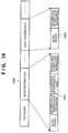
- FIG. 18 illustrates a data structure of an encoded data file 1800 outputted from the multiplexing unit 212 .
- the encoded data file 1800 has a file header holding information necessary for decoding such as size information (the number of pixels in horizontal and vertical directions) of image data, the number of color components, and the number of bits of the respective colors.
- size information the number of pixels in horizontal and vertical directions
- encoded data of respective blocks are stored.
- One block encoded data is of the type of block data 1801 or of the type of block data 1802 shown in FIG. 18 .
- the block data 1801 has a block header indicating the corresponding type, followed by encoded data of identification information generated by the encoding unit 209 , encoded data of an average differential value generated by the encoding unit 210 , and encoded data of gray-level information generated by the encoding unit 211 .
- the block data 1802 has a block header indicating the corresponding type, followed by data obtained by encoding input multi-valued image data by the encoding unit 211 . The grounds of these data structures will be apparent from the following description.
- multi-valued image data to be encoded in the present embodiment indicates a monochrome multi-valued image
- 1 pixel corresponds to 8 bits (256 levels)
- a pixel value indicates a density
- the multi-valued image inputted from the input terminal 251 is temporarily stored in the buffer 203 , then sequentially read out in block units, and sent to the extraction unit 204 , the average differential value generation unit 206 , the substitute color generation unit 207 and the selector 208 .
- a pixel to be extracted is determined, and identification information to identify each pixel within the block as a pixel to be extracted or a pixel not to be extracted is generated. More particularly, the extraction unit 204 generates the identification information by binarizing the multi-valued image read in block units with a threshold value TH 0 . Note that in the identification information, a value “1” indicates that the pixel is a pixel to be extracted, and “0”, the pixel is a pixel not to be extracted.
- the operation of the extraction unit 204 will be described as an example where the input multi-valued image is a 4 ⁇ 4 pixel image as shown in FIG. 15 .
- the threshold value TH 0 for determination of a pixel to be extracted is “200”, among the above-described pixel data, pixel data having “200” or greater value is binarized to “1”, while pixel data having a value less than “200” is binarized to “0”. As a result, “0” or “1” binarized data is generated by each pixel position within each block.
- FIG. 2 shows 1 block (4 ⁇ 4 pixels) identification information binarized as above.
- the threshold value TH 0 is set by a CPU (not shown) or the like, or obtained from a block average value or block histogram.
- the absolute value of the average differential value (D) is equal to or less than a predetermined threshold value, it is determined that extraction is not necessary, and the average differential value and the identification information are cleared to “0”. Otherwise, only the average differential value may be cleared to “0” since the substitution processing to be described later does not actually operate when the average differential value is “0”.
- the absolute value of the average differential value D is equal to or less than a predetermined threshold value, the encoded data of the block becomes only encoded data of gray-level information as indicated with block encoded data 1802 in FIG. 18 .
- FIG. 3 showing the configuration of the average differential value generation unit 206 .
- a multi-valued image inputted from an input terminal 451 is sent to a “1” region average value generation unit 401 and a “0” region average value generation unit 402 .
- identification information outputted from the extraction unit 204 is also inputted from an input terminal 452 , and its value is inverted by the “1” region average value generation unit 401 and an inverter 404 and sent to the “0” region average value generation unit 402 .
- the “1” region average value generation unit 401 calculates an average value (AVE 1 ) of pixel data corresponding to the “1” identification information.
- FIG. 4 shows a configuration of the “1” region average value generation unit 401 .
- the operation of the “1” region average value generation unit 401 will be described with reference to FIG. 4 .
- numeral 551 denotes an input terminal to input identification information outputted from the extraction unit 204 .
- the identification information inputted via the input terminal 551 is supplied to a selector 501 and a counter 502 .
- the selector 501 has input terminals 552 and 553 .
- a fixed value “0” is previously set.
- pixel data of the multi-valued image inputted from the input terminal 451 is inputted into the input terminal 553 .
- the selector 501 selects the data at the input terminal 553 , i.e., the pixel data, and outputs the selected data.
- the selector 501 selects the fixed value “0” set at the input terminal 552 and outputs the selected value.
- An accumulator 503 cumulatively adds the output values from the selector 501 , and supplies the result of cumulative addition to a divider 504 .
- the counter 502 counts the number of “1” value of the identification information for 1 block, and supplies the result of counting to the divider 504 .
- the identification information has “1” or “0” value.
- the output value from the accumulator 503 immediately after input of final data of 1 block is the total sum of pixel values corresponding to “1” value of the identification information in the block of interest. Further, the output value from the counter 502 is the number of “1” value of the identification information. Accordingly, the divider 504 divides the output value from the accumulator 503 by the output value from the counter 502 , thereby obtains the average value in the region where the identification information is “1”, i.e., the average value (AVE 1 ) of pixel data to be extracted. The average value (AVE 1 ) of the pixel data to be extracted is outputted from a terminal 555 . Note that when the output value from the counter 502 is “0”, a value “0” is outputted from the output terminal 555 .
- a controller (not shown) zero-clears (resets) the counter 502 and the accumulator 503 via an initialization signal 554 upon start of calculation of the average value (AVE 1 ) of pixels to be extracted within each block.
- the “1” region average value (AVE 1 ) as the output value from the “1” region average value generation unit 401 is sent to a subtracter 403 .
- the “0” region average value generation unit 402 having the same configuration of that of the “1” region average value generation unit 401 described using FIG. 5 , performs the same operation.
- the identification information inverted by the inverter 404 is inputted into the input terminal 551 .
- the output value from the “0” region average value generation unit 402 is a “0” region average value (AVE 2 ) as an average value of pixel data of a region where the identification information inputted from the input terminal 452 is “0”, i.e., as an average value of pixel data of pixels not be to extracted.
- the “0” region average value (AVE 2 ) is sent to the subtracter 403 .
- the more particular operation of the average differential value generation unit 206 will be described in a case where the 4 ⁇ 4 pixel block multi-valued image data shown in FIG. 15 and the identification information shown in FIG. 2 are inputted.
- pixel data “235”, “239”, “240”, “233”, “235” and “231” correspond to “1” value of the identification information. Accordingly, the average value “235” of the pixel data becomes the output value from the “1” region average value generation unit 401 , i.e., the “1” region average value (AVE 1 ).
- pixel data “65”, “68”, “64”, “66”, “65”, “65”, “64”, “66”, “68” and “67” correspond to “0” value of the identification information. Accordingly, the average value “65” of the pixel data becomes the output value from the “0” region average value generation unit 402 , i.e., the “0” average value (AVE 2 ).
- the output value from the average differential value generation unit 206 i.e., the average differential value (D) becomes “170” as a result of subtraction of the “0” region average value from the “1” region average value by the subtracter 403 .
- the substitute color generation unit 207 subtracts the average differential value (D) outputted form the average differential value generation unit 206 from the respective multi-valued image pixel data within the block outputted from the buffer 203 .
- the result of subtraction is outputted as a substitute color. Note that when the result of subtraction is negative, the substitute color generation unit 207 clips the substitute color of the pixel of interest to “0” (boundary value) and outputs the value.
- the substitute color generation unit 207 Next, an operation of the substitute color generation unit 207 will be described in an example where the input multi-valued image is the 4 ⁇ 4 pixel block pixel data shown in FIG. 15 , and the input average differential value (D) is “170” in the description of the average differential value generation unit 206 .
- the substitute color generation unit 207 subtracts the average differential value “170” from all the pixel data within the block. As described above, when the result of subtraction is a negative value, “0” is outputted as the substitute color value. As a result, the substitute color generation unit 207 outputs 4 ⁇ 4 pixel data shown in FIG. 5 as substitute colors.
- the selector 208 when the input identification information (determination information) is “0”, pixel data of the input multi-valued image corresponding to the position of the identification information is selected. On the other hand, when the identification information is “1”, pixel data of the substitute color outputted from the substitute color generation unit 207 corresponding to the position of the identification information is selected. The above processing is repeated by the block end pixel, thereby gray-level information of the block of interest is obtained.
- the 4 ⁇ 4 pixel block substitute colors shown in FIG. 5 are inputted into the selector 208 and the 4 ⁇ 4 pixel block identification information shown in FIG. 2 is inputted as a control signal into the selector 208 , in the present embodiment, values of one of the pixel groups are substituted such that the difference between the average value (AVE 1 ) of the pixel group for which the identification information is “1” and the average value (AVE 2 ) of the pixel group for which the identification information is “0” is reduced.
- the pixel data of the multi-valued image is selected, on the other hand, in the pixels corresponding to the “1” value of the identification information, the pixel data of the substitute color is selected.
- the output values from the selector 208 4 ⁇ 4 pixel block gray-level information shown in FIG. 6 is outputted.
- the pixel value in the position judged as a character/line image is approximately the same value as that of a pixel value of non-character/line image. That is, the processing is performed as if a natural image including no character/line image is generated.
- the gray-level information shown in FIG. 6 is compressed (lossy encoded) by the encoding unit 211 using e.g. JPEG encoding.
- JPEG encoding e.g. JPEG encoding
- the lossy encoding method is not limited to the JPEG method but any other encoding appropriate to natural images may be applied.
- the identification information outputted from the extraction unit 204 is compressed (lossless encoded) by the encoding unit 209 using run-length encoding.
- the lossless encoding any other encoding appropriate to binary data encoding may be applied.
- the average differential value (D) outputted from the average differential value generation unit 206 is compressed (lossless encoded) by the encoding unit 210 .
- lossless encoding is preferable.
- lossy encoding is in same cases preferred. However, lossless encoding may be employed as long as a target compressibility is obtained.
- the multiplexing unit 212 combines the encoded data from the encoding unit 209 , the encoded data from the encoding unit 210 and the encoded data from the encoding unit 211 so as to facilitate storage into the memory in the subsequent stage, and outputs the combined data from the output terminal 252 .
- the multiplexing unit 212 previously provided with a memory for storing pattern data indicating encoded data for which all the identification information is “0”, determines whether or not the encoded data of the identification information outputted from the encoding unit 209 and the pattern data correspond with each other.
- the multiplexing unit 212 combines the encoded data from the encoding units 209 , 210 and 211 , thereby generates encoded data which is of the same type as that of the block data 1801 in FIG. 18 and outputs the data.
- the multiplexing unit 212 deletes the encoded data from the encoding units 209 and 210 , generates encoded data of the type of the block data 1802 in FIG. 18 using the encoded data from the encoding unit 211 , and outputs the data. In this manner, as described above, the encoded data file which is of the same type as that of the block encoded data 1801 or 1802 in FIG. 18 is generated.
- the multiplexing unit 212 compares the encoded data from the encoding unit 209 with the pattern data.
- the present invention is not limited to this arrangement.
- it may be arranged such that, when the extraction unit 204 generates identification information for 1 block, the extraction unit 204 supplies a signal indicating whether or not all the values of the identification information are “0” to the multiplexing unit 212 .
- the multiplexing unit 212 generates encoded data which is of the same type as that of the block data 1801 or 1802 in accordance with the signal from the extraction unit 204 .
- FIG. 7 is a block diagram showing a configuration of an image decoding apparatus according to the present embodiment.
- numeral 851 denotes an input terminal to input encoded data read from a memory (not shown); 801 , a separation unit to separate the encoded data into encoded identification information, an encoded average differential value (D) and encoded gray-level information; 802 , a first decoding unit to decode the above identification information; 803 , a second decoding unit to decode the above average differential value (D); 804 , a third decoding unit to decode the above gray-level information; and 805 , an image restoration unit to restore a multi-valued image and outputs the result of restoration.
- a separation unit to separate the encoded data into encoded identification information, an encoded average differential value (D) and encoded gray-level information
- 802 a first decoding unit to decode the above identification information
- 803 a second decoding unit to decode the above average differential value (D)
- 804 a third decoding unit to decode the above gray-level information
- 805 an image restoration unit to restore a multi-valued image
- encoded data for 1 block inputted from the input terminal 851 is equivalent to the encoded data outputted from the output terminal 251 in FIG. 1 .
- the separation unit 801 analyzes a block header of the inputted encoded data of the block of interest, and determines whether the encoded data of the block of interest is of the type of the block data 1801 or the type of the block data 1802 in FIG. 18 . When it is determined that the block of interest is of the same type as that of the block data 1801 , the separation unit 801 separates encoded data of identification information, encoded data of average differential value and encoded data of gray-level information, following the block header, and supplies the separated respective encoded data to the corresponding decoding units 802 , 803 and 804 .
- the separation unit 801 is previously provided with a memory for storing pattern data of encoded data for which all the identification information is “0” and pattern data of encoded data of “0” average differential value.
- the separation unit 801 outputs the pattern data of the encoded data for which all the identification information is “0”, previously stored in the memory, to the decoding unit 802 , and outputs the pattern data of the encoded data of “0” average differential value, stored in the memory, to the decoding unit 803 .
- the separation unit 801 outputs the encoded data of gray-level information following the input block header to the decoding unit 804 .
- the decoding unit 802 decodes the input encoded identification information, and output the result of decoding to the image restoration unit 805 .
- the decoding unit 802 corresponding to the encoding unit 209 in FIG. 1 , performs lossless decoding. Accordingly, the identification information outputted from the decoding unit 802 completely corresponds with the identification information outputted from the extraction unit 204 in FIG. 1 .
- the decoding unit 803 corresponding to the encoding unit 210 in FIG. 1 , performs lossless decoding. Accordingly, the average differential value decoded by the decoding unit 803 completely corresponds with the average differential value (D) before encoding outputted from the average differential value generation unit 206 in FIG. 2 .
- the decoding unit 804 decodes the inputted encoded gray-level information for 1 block. As the decoding unit 804 according to the present embodiment decodes lossy encoded data, the result of decoding does not completely correspond with the gray-level data outputted form the selector 208 in FIG. 1 , but gray-level information appropriately maintaining the tonality can be restored.
- the image restoration unit 805 outputs the gray-level information outputted from the decoding unit 804 without any processing. Further, regarding the “1” region of the identification information outputted form the decoding unit 802 , the image restoration unit 805 adds the average differential value (D) outputted from the decoding unit 803 to the gray-level information outputted from the decoding unit 804 and outputs the result of addition.
- D average differential value
- the image restoration unit 805 adds the average differential value “170” to the above gray-level information corresponding to the “1” region of the identification information. Accordingly, as the 1 block image data outputted from the image restoration unit 805 , a 4 ⁇ 4 pixel block multi-valued image shown in FIG. 9 is restored.
- the separation unit 801 when it is determined that the encoded data of the block of interest is of the same type as that of the block data 1802 , the separation unit 801 outputs dummy encoded data of identification information (pattern data) to the decoding unit 802 , and outputs dummy encoded data of average differential value (pattern data) to the decoding unit 803 .
- the present invention is not limited to this arrangement. For example, the following arrangement may be made.
- the separation unit 801 analyzes the block header, determines whether the encoded data of the block of interest is of the type of the block data 1801 or the type of the block data 1802 , and outputs a signal indicating the result of determination to the image restoration unit 805 . Further, when it is determined that the encoded data of the block of interest is of the type of the block data 1802 , the separation unit 801 outputs only the encoded data of the gray-level information following the block header to the decoding unit 804 . When the image restoration unit 805 inputs a signal indicating that the block of interest is of the type of the block data 1801 , the image restoration unit 805 performs the above-described processing.
- the image restoration unit 805 when the image restoration unit 805 inputs a signal indicating that the block of interest is of the same type as that of the block data 1802 , the image restoration unit 805 selects only the result of decoding from the decoding unit 804 and outputs the selected data. In this arrangement, the same result as that of the above-described embodiment can be obtained.
- a pixel for which the identification information is “1” is a pixel to be extracted
- a pixel for which the identification information is “0” may be the pixel to be extracted.
- the substitute pixel is also the pixel for which the identification information is “0”, and the identification information when the absolute value of the average differential value (D) is equal to or less than the predetermined value is all cleared to “1”.
- the substitution processing does not actually operate when the average differential value is cleared to “0”, it may be arranged such that the average differential value (D) is cleared to “0” in stead of clearing all the identification information to “1”.
- 1 block has a size of 4 ⁇ 4 pixels.
- the block size is preferably 8 ⁇ 8 pixels or integral multiple of this size as long as the encoding unit 211 performs the JPEG encoding processing.
- the 4 ⁇ 4 pixel block size in the embodiment is an example for simplification of the explanation.
- the present invention is not particularly limited to separation between a character portion and the other portion.
- the present invention is appropriately employed when a high value group and a low value group exist within a block of a region and these groups are encoded.
- the above-described first embodiment may be realized as a computer program. An example of this arrangement will be described below.
- FIG. 19 is a block diagram showing a configuration of an information processing apparatus (personal computer or the like) employed in the present modification.
- numeral 1901 denotes a CPU for controlling the entire apparatus; 1902 , a ROM holding a boot program and a BIOS; 1903 , a RAM used as a work area for the CPU 1901 ; 1904 , a large capacity external storage device such as a hard disk holding an OS (Operating System), an application program of the present modification and various data files; 1905 , a keyboard; 1906 , a mouse as a pointing device; 1907 , a display control unit including a video memory and a controller to perform drawing processing to the video memory and to output an image from the video memory as a video signal to the outside; 1908 , a display device (CRT, a liquid crystal display device or the like) to input the video signal from the display control unit 1907 and produce a display; 1909 , a network interface; 1910 , a scanner interface; and 1911 , an image scanner.
- CTR a liquid crystal display device
- the CPU 1901 when the power of the present apparatus is turned ON, the CPU 1901 loads the OS from the external storage device 1904 to the RAM 1903 in accordance with the boot program in the ROM 1902 , thereby the apparatus functions as an information processing apparatus. Then, when it is instructed with the keyboard 1905 or the mouse 1906 to start the application program of the present modification, the CPU 1901 loads the corresponding application program from the external storage device 1904 to the RAM 1903 , and executes the program, thereby the apparatus functions as an image processing apparatus.
- a buffer for temporarily storing the image data read with the scanner 1911 and an area for storing various variables are ensured in the RAM 1902 .
- the image scanner 1911 is set so as to read an original in a monochrome multi-value mode (8 bits per 1 pixel). Image data read with the image scanner 1911 becomes luminance value. Note that this is an inverse value to the density value in the above-described first embodiment, and “0” and “1” values upon binarization are inverse values to those in the above-described first embodiment. That is, the difference between the luminance and the density is not a substantial difference, since the present invention is applicable as long as a character/line image pixel and a non-character/line image pixel can be separated.
- FIG. 20 is a flowchart showing the image encoding processing procedure by the application program according to the present modification.
- image data read with the image scanner 1911 is stored into an input buffer in the RAM 1903 .
- header information of a file written into the external storage device 1904 has been already generated.
- image data for 1 block is read from the input buffer.
- the size of 1 block is 8 ⁇ 8 pixels.
- each pixel value within the input 1 block is compared with a preset threshold value TH 0 and binarized.
- the result of binarization referred to as identification information as in the case of the first embodiment, is represented as B(i, j).
- AVE 1 ⁇ B ( i,j ) ⁇ IM ( i,j ) ⁇ / ⁇ B ( i,j )
- step S 3 corresponds to the processing in the “1” region average value generation unit 401 in FIG. 3 .
- AVE 2 ⁇ (1 ⁇ B ( i,j )) ⁇ IM ( i,j ) ⁇ / ⁇ (1 ⁇ B ( i,j ))
- step S 4 corresponds to the processing in the “0” region average value generation unit 402 in FIG. 3 .
- the differential value D is obtained by subtracting the average value AVE 2 from the average value AVE 1 . That is, the processing at step S 5 corresponds to the processing in the subtracter 403 in FIG. 3 .
- step S 6 it is determined whether or not the absolute value of the differential value D is equal to or less than the preset threshold value TH 1 .
- the determination at step S 6 is YES, all the pixel values existing in the block of interest have approximately the same value. Accordingly, regarding the block of interest, JPEG encoding (lossy encoding) is performed at step S 7 . That is, the encoded data of the block of interest corresponds to the block encoded data 1802 in FIG. 18 .
- step S 6 determines whether the absolute value of the differential value D is greater than the threshold value TH 1 .
- the gray-level pixel value after the substitution processing is represented as T(i, j)
- the following expressions are obtained.
- T(i, j) 0 holds
- T(i, j) 0 holds
- B ( i, j ) 0 holds
- T ( i, j ) IM ( i, j ) holds
- the gray-level pixel value T(i, j) obtained by the substitution processing is JPEG-encoded (lossy encoded).
- step S 10 the binary identification information B(i, j) is lossless encoded, and at step S 11 , the differential value D is lossless encoded.
- step S 12 at which the generated encoded data is outputted as a part of the file.
- the encoded data of the block of interest through the processing at steps S 8 to S 11 corresponds to the block encoded data 1801 in FIG. 18 .
- step S 13 it is determined whether or not all the blocks have been subjected to the encoding processing. If NO, the processing from step S 1 is repeated.
- An encoded data file to be decoded is selected by displaying an appropriate GUI screen on the display device 1908 and operating the mouse 1906 by a user.
- step S 21 encoded data for 1 block is inputted from the selected file.
- step S 22 the block header is analyzed and it is determined whether the data is of the type of the block data 1801 or the type of the block data 1802 in FIG. 18 .
- step S 23 When it is determined that the input encoded data is of the type of the block data 1802 , i.e., the encoded data includes only encoded data of gray-level information, the process proceeds to step S 23 , at which JPEG decoding processing is performed.
- the process proceeds to step S 24 .
- step S 24 the binary identification information B(i, j) is decoded, and at step S 25 , the differential value D is decoded.
- step S 26 the gray-level information T(i, j) is decoded.
- step S 28 the image data for 1 block obtained by decoding at step S 23 or S 27 is outputted.
- the image data is outputted to the display control unit 1907 .
- the image data is outputted to the external storage device 1904 .
- step S 29 it is determined whether or not decoding processing for all the blocks has been completed. If NO, the processing from step S 21 is repeated.
- FIG. 10 is a block diagram showing a configuration of the encoding apparatus according to the second embodiment.
- FIG. 10 The configuration in FIG. 10 is the same as that in FIG. 1 except that a low-pass filter unit 1101 is added.
- the output value from the selector 208 in FIG. 1 i.e., the gray-level information is directly encoded by the encoding unit 211 .
- the output value from the selector 208 i.e., a high-frequency component of the gray-level information
- the encoding unit 211 encodes the image data (gray-level information) in which the high-frequency component is suppressed after the low-pass filter processing.
- the low-pass filter (LPF) processing in addition to elimination of noise component, as the boundary between a pixel to be extracted (a pixel for which the identification information is “1”) and a pixel not to be extracted is smoothed, further improvement in the compressibility can be expected. Further, as described above, as almost all edges in the block have been already extracted and eliminated by the previous subtraction processing using average differential value (D), the edges of the restored image are not impaired by application of the low-pass filter. Conversely, as an edge impaired upon input remains in the gray-level information after the extraction (substitution) processing, the impaired edge can be eliminated by the low-pass processing and a steep edge can be obtained upon restoration.
- D average differential value
- FIGS. 11A to 11F are waveform histograms for explaining the operation of the second embodiment.
- FIG. 11A shows an input waveform in an 8 ⁇ 1 one-dimensional block.
- This waveform (block) is divided into regions using a predetermined threshold value (a block average value here), and position information (the identification information in the first embodiment) is extracted as shown in FIG. 11B .
- position information the identification information in the first embodiment
- the average differential value is subtracted from the input waveform (“1” region in FIG. 11A (a pixel for which the identification information is “1”)), thereby gray-level information in FIG. 11D is obtained. Note that at this time, when the result of subtraction is negative, clipping to “0” is performed as described above. Then an LPF is applied to the gray-level information and through compression and decompression, a waveform shown in FIG. 11E is obtained. In the waveform ( FIG. 11E ), the average differential value is added to the “1” region (pixels for which the identification information is “1”), thereby the original waveform (block) is restored as shown in FIG. 1F . As indicated with arrows in FIG. 11F , it is apparent that the edge of the “1” region in the boundary portion is steep.
- a pixel group for which the identification information is “1” is determined as a pixel group to be extracted, and a pixel group for which the identification information is “0”, as a pixel group not to be extracted. Then, an average differential value is subtracted from the values of the respective pixels included in the pixel group to be extracted.
- reversal of the relation between the pixel groups may be realized. That is, it may be arranged such that the pixel group for which the identification information is “0” is determined as a pixel group to be extracted, and the average differential value is added to the values of the respective pixels included in the pixel group.
- the average differential value when the result of addition of the average differential value is over the allowable range of input pixel, the value is clipped to an upper limit value (boundary value). That is, the average differential value may be added or subtracted so as to reduce the respective average values of the pixel group to be extracted and the pixel group not to be extracted.
- an average differential value is subtracted from respective multi-valued image data within a block, and when the result of subtraction is negative, the substitute color is clipped to “0” (lower limit value) and outputted.
- the encoding unit 211 which is e.g. a JPEG encoder, inputs a positive value.
- This arrangement is based on the fact that even when pixels clipped as the substitute color exist, if the number of the pixels is small and the clip width is small, the image quality after restoration is not much influenced. (See FIGS. 11A to 11D ).
- FIG. 22A shows an input waveform in an 8 ⁇ 1 one-dimensional block. This waveform (block) is divided into regions using a predetermined threshold value, thereby identification information is generated ( FIG. 22B ). Then an average value is obtained by region using the identification information ( FIG. 22C ), and an obtained average differential value is subtracted from the “1” region pixel data. The result of subtraction may become a negative value in accordance with threshold value or input waveform.
- FIG. 23 is a block diagram showing a configuration of the encoding apparatus according to the third embodiment.
- the substitute color generation unit 207 in the configuration in FIG. 1 as the first embodiment is replaced with a substitute color generation unit 2301 , and further, a substitute color generation unit 2302 , a comparator 2303 and a selector 2304 are added to the configuration in FIG. 1 .
- Other constituent elements are the same as those in the first embodiment.
- a clip counter which functions as a first count unit to be described later is added to the substitute color generation unit 207 in FIG. 1 of the first embodiment.
- the clip counter is incremented when the identification information is “1” and the result of subtraction of the average differential value (D) from the respective multi-valued image pixel data within a block outputted from the buffer 203 is negative.
- the substitute color generation unit 2301 outputs a substitute color (a) by the same method as that used in the substitute color generation unit 207 , and outputs the value of the clip counter as a clip count value (a).
- the clip counter is cleared to “0”.
- the clip count value (a) represents the number of pixels clipped to “0” (lower limit value) among pixels of the substitute color corresponding to the “1” identification information within the block.
- the selector 208 selects pixel data of input multi-valued image corresponding to the identification information and outputs the selected pixel data.
- the selector 208 selects pixel data of the substitute color (a) outputted from the substitute color generation unit 2302 corresponding to the position of the identification information and outputs the selected pixel data. This processing is repeated by the block end pixel, thereby gray-level information (a) of the block of interest is obtained.
- a block average value is “76”
- the identification information is as shown in FIG. 25 .
- the average differential value (D) is “200” based on FIGS. 24 and 25 .
- the average differential value “200” is subtracted from all the pixel data within the block.
- the substitute color generation unit 2301 clips the substitute color value to “0” and outputs the value.
- the identification information at that time is “1” indicating a pixel to be extracted
- the clip counter is incremented.
- the value of the clip counter is “2”.
- the substitute color generation unit 2301 outputs 4 ⁇ 4 pixel data as a substitute color (a) shown in FIG. 26 , and outputs the value of the clip counter, “2”, as a clip count value (a).
- the selector 208 selects pixels corresponding to “1” identification information shown in FIG. 25 among the pixels of the substitute color (a) shown in FIG. 26 , and pixels corresponding to the “0” identification information among the multi-valued image shown in FIG. 24 , and outputs them. As a result, the selector 208 outputs gray-level information (a) shown in FIG. 27 . As shown in FIG. 27 , a pixel value in a position determined as a character/line image is approximately the same as a pixel value of non-character/non-line image.
- the substitute color generation unit 2302 adds the average differential value (D) outputted from the average differential value generation unit 206 to pixel data of the respective multi-valued image within the block outputted from the buffer 203 . Then the result of addition is outputted as a substitute color (b). Note that when the result of addition exceeds an allowable range of pixel data, the value is clipped to an upper limit value (boundary value).
- the substitute color generation unit 2302 has a clip counter which functions as a second count unit.
- the clip counter of the substitute color generation unit 2302 is different from the clip counter of the substitute color generation unit 2301 . That is, the clip counter of the substitute color generation unit 2302 is incremented when the identification information is “0” and the result of addition of the average differential value (D) to the respective multi-valued image pixel data within the block outputted from the buffer 203 exceeds the upper limit value (boundary value) of the allowable range of pixel data. Then, when the substitute color (b) and the clip count value (b) have been outputted, the clip counter is cleared to “0”.
- the clip count value (b) indicates the number of pixels in the substitute color within the block, corresponding to the “0” identification information, clipped to the upper limit value (boundary value).
- the selector 2304 has the same function as that of the selector 208 . Note that as the identification information (determination information) is inverted and inputted into the selector 2304 , when the identification information (determination information) is “1”, the selector 2304 selects pixel data of the input multi-valued image corresponding to the position of the identification information and outputs the selected pixel data. On the other hand, when the identification information is “0”, the selector 2304 selects pixel data of the substitute color (b) outputted from the substitute color generation unit 2302 corresponding to the position of the identification information and outputs the selected pixel data. This processing is repeated by the block end pixel, thereby gray-level information (b) of the block of interest is obtained.
- the selector 208 functions as a first substitution unit, and the selector 2304 , as a second substitution unit.
- the identification information is as shown in FIG. 25 .
- the average differential value (D) is “200” based on FIGS. 24 and 25 . Note that as inverted identification information is inputted into the substitute color generation unit 2302 , a pixel corresponding to the “1” identification information becomes a pixel not to be extracted, and a pixel corresponding to the “0” identification information becomes a pixel to be extracted.
- the substitute color generation unit 2302 adds the average differential value “200” to all the pixel data within the block.
- the substitute color 2302 clips he value of the substitute color to “255” and outputs the value.
- the identification information at that time is “0” indicating a pixel to be extracted
- the clip counter is incremented. In this example, there is no pixel to be extracted, and the value of the clip counter is “0”.
- the substitute color generation unit 2302 outputs 4 ⁇ 4 pixel data shown in FIG. 28 as a substitute color (b), and outputs the value of the clip counter, “0”, as a clip count value (b).
- the selector 2304 selects pixels corresponding to the “0” identification information shown in FIG. 25 among the pixels of the substitute color (b) shown in FIG. 28 and pixels corresponding to the “1” identification information among the multivalued image pixels shown in FIG. 24 , and outputs them.
- the gray-level information (b) outputted from the selector 2302 is as shown in FIG. 29 .
- the pixel value in the position judged as a non-character/line image is approximately the same value as that of a pixel value of character/line image.
- the comparator 2303 compares the clip count value (a) outputted from the substitute color generation unit 2301 with the clip count value (b) outputted from the substitute color generation unit 2302 upon completion of processing for 1 block. Then, when the clip count value (a) is equal to or less than the clip count value (b), the comparator 2302 outputs “0”, otherwise, outputs “1”, as a determination signal SEL.
- the selector 2305 having a block buffer (not shown) selects the gray-level information (a) inputted from the selector 208 and outputs the selected information, on the other hand, when the SEL signal is “1”, the selector 2305 selects the gray-level information (b) inputted from the selector 2304 , and outputs the selected information, in synchronization with the determination signal from the comparator 2303 . That is, the selector 2305 selects gray-level information in which the number of clipped pixels is smaller.
- the gray-level information outputted from the selector 2305 is compressed by the same compression method as that in the first embodiment (lossy encoded) by the encoding unit 211 . Further, the identification information outputted from the extraction unit 204 and the average differential value outputted from the average differential value generation unit 206 are compressed by the same compression method as that in the first embodiment (lossless encoded) by the encoding unit 209 and the encoding unit 210 .
- a multiplexing unit 2306 combines the encoded data compressed by the encoding unit 209 , the encoding unit 210 and the encoding unit 211 , and the SEL signal (selection information) to notify the decoding unit of the type of the gray-level information (gray-level information (a) or gray-level information (b)) encoded by the encoding unit 211 , for storage in a memory in the subsequent stage, and output the combined data from the output terminal 252 .
- the SEL signal selection information
- the identification (selection) of the differential value is needed.
- the fourth embodiment by scheming the setting of the differential value so as not to change the minimum value in the area corresponding to identification information “1” to negative, the problem of the substituted pixel value being negative can be solved without using the identification (selection) signal.
- FIG. 30 is a block diagram showing a configuration of the encoding apparatus according to the fourth embodiment.
- the average differential value substitution unit 2310 compares a minimum value of pixels corresponding to the “1” identification information outputted from the extraction unit 204 within a block outputted from the buffer 203 , with a differential value outputted from the average differential value generation unit 206 , and selects a less value and outputs the selected value.
- the value selected and outputted by the average differential value substitution unit 2310 will be referred to as a correction value.
- FIG. 31 is a block diagram of the average differential value substitution unit 2310 .
- a minimum value detection unit 2401 inputs the respective pixel data of multi-valued image within the block outputted from the buffer 203 , and outputs a minimum value of the pixel data corresponding to the “1” identification information outputted from the extraction unit 204 . Then a comparator 2402 compares the minimum value with the differential value outputted from the average differential value generation unit 206 . When the differential value is less than the minimum value, the comparator 2402 outputs “0”, otherwise, outputs “1”, as a selection signal. Then a selector 2403 selects a less one of the minimum pixel value of the multi-valued image and the differential value based on the selection signal, and outputs the selected value as a correction value.
- the average differential value substitution unit 2301 When pixel data of a 4 ⁇ 4 pixel block as shown in FIG. 24 is inputted, the differential value (D) is “200”, and the identification information is as shown in FIG. 25 .
- the minimum value of pixel data corresponding to the “1” identification information is “104”, and the minimum value, in comparison with the differential value (D), is less than the differential value (D). Accordingly, the average differential value substitution unit 2310 outputs the minimum value “104” as a correction value.
- the subsequent processing is the same as that in the first embodiment.
- the substitute color generation unit 207 subtracts the substitute value outputted from the average differential value generation unit 206 from the respective pixel data of multi-valued image within the block outputted from the buffer 203 .
- the selector 208 does not select the value.
- FIGS. 32A to 32G are waveform histograms showing an advantage of the fourth embodiment.
- FIG. 32A shows an input waveform in an 8 ⁇ 1 one-dimensional block.
- This waveform (block) is divided into regions using a predetermined threshold value (e.g. a block average value) thereby identification information is generated ( FIG. 32B ).
- a predetermined threshold value e.g. a block average value
- FIG. 32C an average value is obtained by region using the identification information
- FIG. 32D an obtained temporary average differential value is compared with pixel data minimum value in the “1” region, and a less value is subtracted as an average differential value ( FIG. 32D ) from the input waveform.
- FIG. 32E the result of subtraction has no negative value pixel. Accordingly, after the compression/decompression processing ( FIG. 32F ), when the average differential value is added to the “1” region, the tonality is maintained as shown in an output waveform after restoration ( FIG. 32G ).
- the correction value is subtracted from the pixel values of the “1” identification information, however, the correction value may be added to the pixel values of the “0” identification information.
- the average differential value substitution unit 2310 obtains a maximum pixel value of pixels corresponding to the “0” identification information outputted from the extraction unit 204 within the block outputted from the buffer 203 . Then the average differential value substitution unit 2310 compares a differential value between the maximum pixel value and an upper limit value (“255” in this embodiment) of pixel value, with the average differential value outputted from the average differential value generation unit 206 , and outputs a less value as a correction value.
- the substitute color generation unit 207 adds the substitute value outputted from the average differential value generation unit 206 to the respective pixel data of multi-valued image within the block outputted from the buffer 203 . At this time, when the result of addition exceed the upper limit vale, the selector 208 does not select the value.
- the block size is 4 ⁇ 4 (or 8 ⁇ 1) pixels.
- the block size is preferably determined in accordance with encoding to compress gray-level information (e.g., orthogonal transformation size).
- the block size is preferably an integral multiple of DTC block size (8 ⁇ 8).
- the size of 1 block is 8 ⁇ 16 pixels, two 8 ⁇ 8 pixels exist in this block.
- the encoding unit 211 performs DCT transformation, quantization and entropy encoding processing on two 8 ⁇ 8 pixel blocks.
- the present invention can be realized with a computer program.
- a computer program is stored in a computer-readable storage medium such as a CD-ROM. Then the medium is set in a reading device (CD-ROM drive or the like) of a computer, and the program is duplicated or installed into the system, thereby the program becomes executable. Accordingly, it is apparent that the computer-readable storage medium is included in the scope of the present invention.
Abstract
Description
AVE1={ΣB(i,j)×IM(i,j)}/ΣB(i,j)
Note that Σ is a combined function of i, j=0, 1, . . . 7. Further, when ΣB(i, j)=0 holds, AVE1=0 holds.
AVE2={Σ(1−B(i,j))×IM(i,j)}/Σ(1−B(i,j))
When Σ(1−B(i, j))=0 holds, AVE2=0 holds.
When B(i, j)=1 holds, T(i, j)=IM(i, j)−D holds
When B(i, j)=0 holds, T(i, j)=IM(i, j) holds
When B(i, j)=1 holds, IM′(i, j)=T(i, j)+D holds
When B(i, j)=0 holds, IM′(i, j)=T(i, j) holds
{Pixel value corresponding to “1” identification information}>{pixel value corresponding to “0” identification information}
Claims (14)
Applications Claiming Priority (6)
| Application Number | Priority Date | Filing Date | Title |
|---|---|---|---|
| JP2006216260 | 2006-08-08 | ||
| JP2006-216260 | 2006-08-08 | ||
| JP2007-148627 | 2007-06-04 | ||
| JP2007148627 | 2007-06-04 | ||
| JP2007-180157 | 2007-07-09 | ||
| JP2007180157A JP4956304B2 (en) | 2006-08-08 | 2007-07-09 | Image encoding apparatus, control method therefor, computer program, and computer-readable storage medium |
Publications (2)
| Publication Number | Publication Date |
|---|---|
| US20080037883A1 US20080037883A1 (en) | 2008-02-14 |
| US7903888B2 true US7903888B2 (en) | 2011-03-08 |
Family
ID=39050874
Family Applications (1)
| Application Number | Title | Priority Date | Filing Date |
|---|---|---|---|
| US11/835,099 Expired - Fee Related US7903888B2 (en) | 2006-08-08 | 2007-08-07 | Image encoding apparatus and image decoding apparatus |
Country Status (1)
| Country | Link |
|---|---|
| US (1) | US7903888B2 (en) |
Cited By (1)
| Publication number | Priority date | Publication date | Assignee | Title |
|---|---|---|---|---|
| US20080317362A1 (en) * | 2007-06-20 | 2008-12-25 | Canon Kabushiki Kaisha | Image encoding apparatus and image decoding apparauts, and control method thereof |
Families Citing this family (15)
| Publication number | Priority date | Publication date | Assignee | Title |
|---|---|---|---|---|
| JP2008042401A (en) * | 2006-08-03 | 2008-02-21 | Canon Inc | Information processing apparatus and information processing method |
| JP4829836B2 (en) * | 2007-04-26 | 2011-12-07 | キヤノン株式会社 | Image encoding apparatus, control method for image encoding apparatus, computer program, decoding apparatus, and computer-readable storage medium |
| JP4871822B2 (en) * | 2007-09-20 | 2012-02-08 | キヤノン株式会社 | Image coding apparatus and control method thereof |
| US8238437B2 (en) * | 2007-09-20 | 2012-08-07 | Canon Kabushiki Kaisha | Image encoding apparatus, image decoding apparatus, and control method therefor |
| US8145794B2 (en) | 2008-03-14 | 2012-03-27 | Microsoft Corporation | Encoding/decoding while allowing varying message formats per message |
| US8044831B2 (en) * | 2009-01-16 | 2011-10-25 | Canon Kabushiki Kaisha | Decoding apparatus and control method thereof |
| US8948286B2 (en) * | 2009-10-20 | 2015-02-03 | Wisconsin Alumni Research Foundation | Wireless communication system mapping data bits to symbol bit positions according to error rates of those bit positions and data content |
| CN102668566B (en) | 2009-10-22 | 2016-05-04 | 汤姆森特许公司 | Method and apparatus by DC intra prediction mode for Video coding and decoding |
| JP2011166326A (en) * | 2010-02-05 | 2011-08-25 | Sony Corp | Image processing device and method |
| JP5501041B2 (en) * | 2010-03-15 | 2014-05-21 | キヤノン株式会社 | Image processing apparatus, image processing method, and program |
| US10257393B2 (en) | 2016-02-12 | 2019-04-09 | Contrast, Inc. | Devices and methods for high dynamic range video |
| US10264196B2 (en) | 2016-02-12 | 2019-04-16 | Contrast, Inc. | Systems and methods for HDR video capture with a mobile device |
| US10554901B2 (en) | 2016-08-09 | 2020-02-04 | Contrast Inc. | Real-time HDR video for vehicle control |
| WO2020036957A1 (en) * | 2018-08-14 | 2020-02-20 | Contrast, Inc. | Image compression |
| CA3109667A1 (en) | 2018-08-14 | 2020-02-20 | Contrast, Inc. | Image processing noise reduction |
Citations (10)
| Publication number | Priority date | Publication date | Assignee | Title |
|---|---|---|---|---|
| JPH03254573A (en) | 1990-03-05 | 1991-11-13 | Canon Inc | Encoding device for color picture |
| JPH0440074A (en) | 1990-06-05 | 1992-02-10 | Canon Inc | Picture encoding device |
| JPH04326669A (en) | 1991-04-26 | 1992-11-16 | Canon Inc | Picture encoding device |
| US5321532A (en) | 1989-11-20 | 1994-06-14 | Canon Kabushiki Kaisha | Image processing apparatus |
| US5464173A (en) | 1994-12-16 | 1995-11-07 | The United States Of America As Represented By The Secretary Of The Navy | Subassembly means |
| US5774634A (en) | 1990-07-31 | 1998-06-30 | Canon Kabushiki Kaisha | Image processing method and apparatus |
| US6252992B1 (en) | 1994-08-08 | 2001-06-26 | Canon Kabushiki Kaisha | Variable length coding |
| JP2002077631A (en) | 2000-08-25 | 2002-03-15 | Canon Inc | Image compression apparatus, image expansion apparatus, its method and recording medium |
| US20020037100A1 (en) * | 2000-08-25 | 2002-03-28 | Yukari Toda | Image processing apparatus and method |
| US6546052B1 (en) * | 1998-05-29 | 2003-04-08 | Canon Kabushiki Kaisha | Image processing apparatus and method, and computer-readable memory |
-
2007
- 2007-08-07 US US11/835,099 patent/US7903888B2/en not_active Expired - Fee Related
Patent Citations (11)
| Publication number | Priority date | Publication date | Assignee | Title |
|---|---|---|---|---|
| US5321532A (en) | 1989-11-20 | 1994-06-14 | Canon Kabushiki Kaisha | Image processing apparatus |
| JPH03254573A (en) | 1990-03-05 | 1991-11-13 | Canon Inc | Encoding device for color picture |
| JPH0440074A (en) | 1990-06-05 | 1992-02-10 | Canon Inc | Picture encoding device |
| US5774634A (en) | 1990-07-31 | 1998-06-30 | Canon Kabushiki Kaisha | Image processing method and apparatus |
| US5903360A (en) | 1990-07-31 | 1999-05-11 | Canon Kabushiki Kaisha | Discriminating an image data characteristic and controlling storage of the data accordingly |
| JPH04326669A (en) | 1991-04-26 | 1992-11-16 | Canon Inc | Picture encoding device |
| US6252992B1 (en) | 1994-08-08 | 2001-06-26 | Canon Kabushiki Kaisha | Variable length coding |
| US5464173A (en) | 1994-12-16 | 1995-11-07 | The United States Of America As Represented By The Secretary Of The Navy | Subassembly means |
| US6546052B1 (en) * | 1998-05-29 | 2003-04-08 | Canon Kabushiki Kaisha | Image processing apparatus and method, and computer-readable memory |
| JP2002077631A (en) | 2000-08-25 | 2002-03-15 | Canon Inc | Image compression apparatus, image expansion apparatus, its method and recording medium |
| US20020037100A1 (en) * | 2000-08-25 | 2002-03-28 | Yukari Toda | Image processing apparatus and method |
Cited By (2)
| Publication number | Priority date | Publication date | Assignee | Title |
|---|---|---|---|---|
| US20080317362A1 (en) * | 2007-06-20 | 2008-12-25 | Canon Kabushiki Kaisha | Image encoding apparatus and image decoding apparauts, and control method thereof |
| US8213727B2 (en) * | 2007-06-20 | 2012-07-03 | Canon Kabushiki Kaisha | Image encoding apparatus and image decoding apparatus, and control method thereof |
Also Published As
| Publication number | Publication date |
|---|---|
| US20080037883A1 (en) | 2008-02-14 |
Similar Documents
| Publication | Publication Date | Title |
|---|---|---|
| US7903888B2 (en) | Image encoding apparatus and image decoding apparatus | |
| JP4956304B2 (en) | Image encoding apparatus, control method therefor, computer program, and computer-readable storage medium | |
| US8270716B2 (en) | Selectively compressing picture and text areas of an image to maintain highest quality and effective compaction | |
| US8213727B2 (en) | Image encoding apparatus and image decoding apparatus, and control method thereof | |
| JP4979655B2 (en) | Image coding apparatus and control method thereof | |
| JP5179889B2 (en) | Method and apparatus for effectively compressing and restoring binary video | |
| US8452112B2 (en) | Image encoding apparatus and method of controlling the same | |
| US8041135B2 (en) | Image encoding apparatus and control method thereof | |
| US8031954B2 (en) | Image encoding apparatus and control method thereof using prediction encoding and pixel classification | |
| JP2006180456A (en) | Image compressor, image decoder, image converter and image processing method | |
| US8244033B2 (en) | Image encoding apparatus, image decoding apparatus, and control method thereof | |
| US8111930B2 (en) | Image encoding apparatus and decoding apparatus, and control method thereof | |
| JP5101962B2 (en) | Image coding apparatus, control method therefor, and computer program | |
| US8023756B2 (en) | Image encoding apparatus and method of controlling same | |
| JP3108133B2 (en) | Adaptive coding of color document images | |
| US7257260B2 (en) | Method and a device for processing digital image | |
| JP5086777B2 (en) | Image encoding apparatus, control method therefor, computer program, and computer-readable storage medium | |
| JPH06178122A (en) | Adaptive encoding device for color image | |
| JP2009260747A (en) | Image encoding device, and control method thereof | |
| JP4757172B2 (en) | Image coding apparatus and control method thereof | |
| JP4971881B2 (en) | Image encoding apparatus, image decoding apparatus, and control method thereof | |
| JP4006276B2 (en) | Image recognition method, image recognition apparatus, and computer program | |
| JP4743883B2 (en) | Image coding apparatus and control method thereof | |
| JPH08307666A (en) | Data processing unit for multi-gradation image with document and photograph in existence in mixture | |
| EP1170956A2 (en) | Method and system for compressing motion image information |
Legal Events
| Date | Code | Title | Description |
|---|---|---|---|
| AS | Assignment |
Owner name: CANON KABUSHIKI KAISHA, JAPAN Free format text: ASSIGNMENT OF ASSIGNORS INTEREST;ASSIGNORS:TSUTSUMI, TAKAYUKI;ISHIKAWA, HISASHI;REEL/FRAME:019812/0388 Effective date: 20070801 |
|
| FEPP | Fee payment procedure |
Free format text: PAYOR NUMBER ASSIGNED (ORIGINAL EVENT CODE: ASPN); ENTITY STATUS OF PATENT OWNER: LARGE ENTITY |
|
| STCF | Information on status: patent grant |
Free format text: PATENTED CASE |
|
| FPAY | Fee payment |
Year of fee payment: 4 |
|
| MAFP | Maintenance fee payment |
Free format text: PAYMENT OF MAINTENANCE FEE, 8TH YEAR, LARGE ENTITY (ORIGINAL EVENT CODE: M1552); ENTITY STATUS OF PATENT OWNER: LARGE ENTITY Year of fee payment: 8 |
|
| FEPP | Fee payment procedure |
Free format text: MAINTENANCE FEE REMINDER MAILED (ORIGINAL EVENT CODE: REM.); ENTITY STATUS OF PATENT OWNER: LARGE ENTITY |
|
| LAPS | Lapse for failure to pay maintenance fees |
Free format text: PATENT EXPIRED FOR FAILURE TO PAY MAINTENANCE FEES (ORIGINAL EVENT CODE: EXP.); ENTITY STATUS OF PATENT OWNER: LARGE ENTITY |
|
| STCH | Information on status: patent discontinuation |
Free format text: PATENT EXPIRED DUE TO NONPAYMENT OF MAINTENANCE FEES UNDER 37 CFR 1.362 |
|
| FP | Lapsed due to failure to pay maintenance fee |
Effective date: 20230308 |