US7907097B2 - Self-supporting unitary feed assembly - Google Patents
Self-supporting unitary feed assembly Download PDFInfo
- Publication number
- US7907097B2 US7907097B2 US11/779,064 US77906407A US7907097B2 US 7907097 B2 US7907097 B2 US 7907097B2 US 77906407 A US77906407 A US 77906407A US 7907097 B2 US7907097 B2 US 7907097B2
- Authority
- US
- United States
- Prior art keywords
- feed assembly
- waveguide
- reflector
- sub reflector
- proximal end
- Prior art date
- Legal status (The legal status is an assumption and is not a legal conclusion. Google has not performed a legal analysis and makes no representation as to the accuracy of the status listed.)
- Expired - Fee Related, expires
Links
- 239000000463 material Substances 0.000 claims abstract description 14
- 239000003989 dielectric material Substances 0.000 claims abstract description 13
- 238000001746 injection moulding Methods 0.000 claims abstract description 6
- 238000003754 machining Methods 0.000 claims abstract description 6
- 238000000034 method Methods 0.000 claims description 13
- 239000011248 coating agent Substances 0.000 claims description 7
- 238000000576 coating method Methods 0.000 claims description 7
- 238000004519 manufacturing process Methods 0.000 claims description 5
- MYRTYDVEIRVNKP-UHFFFAOYSA-N 1,2-Divinylbenzene Chemical compound C=CC1=CC=CC=C1C=C MYRTYDVEIRVNKP-UHFFFAOYSA-N 0.000 claims description 4
- RYGMFSIKBFXOCR-UHFFFAOYSA-N Copper Chemical compound [Cu] RYGMFSIKBFXOCR-UHFFFAOYSA-N 0.000 claims description 3
- 229910052802 copper Inorganic materials 0.000 claims description 3
- 239000010949 copper Substances 0.000 claims description 3
- 229910052751 metal Inorganic materials 0.000 claims description 3
- 239000002184 metal Substances 0.000 claims description 3
- 230000007704 transition Effects 0.000 claims description 3
- 239000004793 Polystyrene Substances 0.000 claims description 2
- BQCADISMDOOEFD-UHFFFAOYSA-N Silver Chemical compound [Ag] BQCADISMDOOEFD-UHFFFAOYSA-N 0.000 claims description 2
- 229910052782 aluminium Inorganic materials 0.000 claims description 2
- XAGFODPZIPBFFR-UHFFFAOYSA-N aluminium Chemical compound [Al] XAGFODPZIPBFFR-UHFFFAOYSA-N 0.000 claims description 2
- PCHJSUWPFVWCPO-UHFFFAOYSA-N gold Chemical compound [Au] PCHJSUWPFVWCPO-UHFFFAOYSA-N 0.000 claims description 2
- 229910052737 gold Inorganic materials 0.000 claims description 2
- 239000010931 gold Substances 0.000 claims description 2
- 229920002223 polystyrene Polymers 0.000 claims description 2
- 229910052709 silver Inorganic materials 0.000 claims description 2
- 239000004332 silver Substances 0.000 claims description 2
- 239000007787 solid Substances 0.000 description 9
- 230000005855 radiation Effects 0.000 description 4
- 230000008901 benefit Effects 0.000 description 3
- 230000009977 dual effect Effects 0.000 description 3
- 230000007613 environmental effect Effects 0.000 description 3
- 239000000853 adhesive Substances 0.000 description 2
- 230000001070 adhesive effect Effects 0.000 description 2
- 230000000712 assembly Effects 0.000 description 2
- 238000000429 assembly Methods 0.000 description 2
- 238000013461 design Methods 0.000 description 2
- 238000002347 injection Methods 0.000 description 2
- 239000007924 injection Substances 0.000 description 2
- 238000012986 modification Methods 0.000 description 2
- 230000004048 modification Effects 0.000 description 2
- 238000005457 optimization Methods 0.000 description 2
- 230000010287 polarization Effects 0.000 description 2
- 229920000642 polymer Polymers 0.000 description 2
- 238000000926 separation method Methods 0.000 description 2
- 229910045601 alloy Inorganic materials 0.000 description 1
- 239000000956 alloy Substances 0.000 description 1
- QVGXLLKOCUKJST-UHFFFAOYSA-N atomic oxygen Chemical compound [O] QVGXLLKOCUKJST-UHFFFAOYSA-N 0.000 description 1
- 230000004888 barrier function Effects 0.000 description 1
- 230000005540 biological transmission Effects 0.000 description 1
- 230000000903 blocking effect Effects 0.000 description 1
- 230000015556 catabolic process Effects 0.000 description 1
- 230000008878 coupling Effects 0.000 description 1
- 238000010168 coupling process Methods 0.000 description 1
- 238000005859 coupling reaction Methods 0.000 description 1
- 238000005388 cross polarization Methods 0.000 description 1
- 230000007812 deficiency Effects 0.000 description 1
- 238000006731 degradation reaction Methods 0.000 description 1
- 238000009826 distribution Methods 0.000 description 1
- 230000000694 effects Effects 0.000 description 1
- 238000009713 electroplating Methods 0.000 description 1
- 230000008030 elimination Effects 0.000 description 1
- 238000003379 elimination reaction Methods 0.000 description 1
- 238000005286 illumination Methods 0.000 description 1
- 238000003780 insertion Methods 0.000 description 1
- 230000037431 insertion Effects 0.000 description 1
- 238000009434 installation Methods 0.000 description 1
- 150000002739 metals Chemical class 0.000 description 1
- 238000000465 moulding Methods 0.000 description 1
- 230000003647 oxidation Effects 0.000 description 1
- 238000007254 oxidation reaction Methods 0.000 description 1
- 229910052760 oxygen Inorganic materials 0.000 description 1
- 239000001301 oxygen Substances 0.000 description 1
- 238000010422 painting Methods 0.000 description 1
- 230000001902 propagating effect Effects 0.000 description 1
- 239000013598 vector Substances 0.000 description 1
- XLYOFNOQVPJJNP-UHFFFAOYSA-N water Substances O XLYOFNOQVPJJNP-UHFFFAOYSA-N 0.000 description 1
Images


Classifications
-
- H—ELECTRICITY
- H01—ELECTRIC ELEMENTS
- H01Q—ANTENNAS, i.e. RADIO AERIALS
- H01Q19/00—Combinations of primary active antenna elements and units with secondary devices, e.g. with quasi-optical devices, for giving the antenna a desired directional characteristic
- H01Q19/10—Combinations of primary active antenna elements and units with secondary devices, e.g. with quasi-optical devices, for giving the antenna a desired directional characteristic using reflecting surfaces
- H01Q19/18—Combinations of primary active antenna elements and units with secondary devices, e.g. with quasi-optical devices, for giving the antenna a desired directional characteristic using reflecting surfaces having two or more spaced reflecting surfaces
- H01Q19/19—Combinations of primary active antenna elements and units with secondary devices, e.g. with quasi-optical devices, for giving the antenna a desired directional characteristic using reflecting surfaces having two or more spaced reflecting surfaces comprising one main concave reflecting surface associated with an auxiliary reflecting surface
- H01Q19/193—Combinations of primary active antenna elements and units with secondary devices, e.g. with quasi-optical devices, for giving the antenna a desired directional characteristic using reflecting surfaces having two or more spaced reflecting surfaces comprising one main concave reflecting surface associated with an auxiliary reflecting surface with feed supported subreflector
-
- H—ELECTRICITY
- H01—ELECTRIC ELEMENTS
- H01Q—ANTENNAS, i.e. RADIO AERIALS
- H01Q1/00—Details of, or arrangements associated with, antennas
- H01Q1/12—Supports; Mounting means
- H01Q1/22—Supports; Mounting means by structural association with other equipment or articles
- H01Q1/24—Supports; Mounting means by structural association with other equipment or articles with receiving set
-
- H—ELECTRICITY
- H01—ELECTRIC ELEMENTS
- H01Q—ANTENNAS, i.e. RADIO AERIALS
- H01Q1/00—Details of, or arrangements associated with, antennas
- H01Q1/52—Means for reducing coupling between antennas; Means for reducing coupling between an antenna and another structure
- H01Q1/526—Electromagnetic shields
-
- H—ELECTRICITY
- H01—ELECTRIC ELEMENTS
- H01Q—ANTENNAS, i.e. RADIO AERIALS
- H01Q19/00—Combinations of primary active antenna elements and units with secondary devices, e.g. with quasi-optical devices, for giving the antenna a desired directional characteristic
- H01Q19/06—Combinations of primary active antenna elements and units with secondary devices, e.g. with quasi-optical devices, for giving the antenna a desired directional characteristic using refracting or diffracting devices, e.g. lens
- H01Q19/09—Combinations of primary active antenna elements and units with secondary devices, e.g. with quasi-optical devices, for giving the antenna a desired directional characteristic using refracting or diffracting devices, e.g. lens wherein the primary active element is coated with or embedded in a dielectric or magnetic material
Definitions
- This invention relates to feed assemblies for reflector antennas. More particularly, the invention provides improvements in reflector antenna feed assembly electrical performance and cost efficiency via a unitary solid dielectric self supporting feed assembly.
- Reflector antennas focus a signal received by a dish shaped reflector upon the feed horn of a centrally mounted receiver. Because the dish shaped reflector only focuses a signal received from a single direction upon the receiver or a sub reflector that further directs the signal to the receiver, reflector antennas are highly directional. When the reflector antenna is used to transmit a signal, the signals travel in reverse, also with high directivity.
- Reflector antennas with a sub reflector supported and fed by a waveguide are relatively cost efficient and allow, for example, location of the transmitter and or receiver in an easily accessible location on the back of the reflector. This configuration eliminates the need for a support structure that spans the face of the reflector, partially blocking the reflector, and signal losses associated with passing the signal through an extended waveguide or cable routed along the support structure.
- a waveguide with a generally circular or elliptical cross section provides the antenna with dual polarization capability.
- Electrical performance of a dual polarized reflector antenna with a self supported feed is typically measured with respect to gain, cross polarization, edge illumination and return loss characteristics.
- Prior reflector antenna feed assemblies typically comprise a sub reflector attached to a waveguide by a dielectric block that positions the sub reflector at a desired orientation and distance from the end of the waveguide.
- the reflector antenna may focus the signal upon a feed horn formed at a waveguide end or a separately supported sub reflector that then focuses the signal upon a feed horn/waveguide.
- a dielectric cover, radome or other environmental seal is applied to protect the open end of the waveguide.
- the metal waveguides are typically structural elements with a significant thickness, creating edge radiation characteristics that contribute to the generation of backlobes in the antenna signal pattern.
- U.S. Pat. No. 6,919,855 issued Jul. 19, 2005 to Hills, assigned to Andrew Corporation as is the present invention describes dielectric blocks incorporating corrugations in the dielectric surface for pattern and return loss optimization.
- a subreflector is formed by metalizing the desired subreflector surface of the dielectric block.
- U.S. Pat. No. 6,985,120 issued Jan. 10, 2006 to Lewry et al., assigned to Andrew Corporation as is the present invention describes a reflector antenna with a self supported feed assembly formed as a hollow dielectric waveguide and cone coupled at the narrow end to the reflector dish and at the wide end joined to a sub reflector surface.
- the waveguide and sub reflector surfaces Formed via injection molding from a dielectric material, the waveguide and sub reflector surfaces have a thin metallic surface coating to contain and reflect radio frequency signals.
- a slight taper along at least the waveguide inner diameter to improve injection molding mold separation, degrades the electrical performance.
- the thickness of the dielectric along the cone and waveguide portions is a trade off between strength and an impedance discontinuity that is difficult to match for, without adding an additional impedance matching element.
- FIG. 1 is a chart demonstrating the cut off frequency for TE11 and TM01 modes with respect to waveguide diameter for solid dielectric and air filled circular waveguides.
- FIG. 2 is a schematic isometric view of a first embodiment of the invention.
- FIG. 3 is a side section, one half removed for clarity, view of a feed assembly according to the first embodiment of the invention.
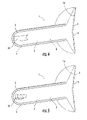
- FIG. 4 is an isometric cut-away view of a feed assembly according to the first embodiment of the invention, showing an alternative form of an impedance transformer.
- FIG. 5 is an isometric cut-away view of a feed assembly according to the first embodiment of the invention, showing another alternative form of an impedance transformer.
- FIG. 6 is a chart showing the computed return loss for the feed assembly of FIG. 2 .
- FIG. 7 is a chart showing the measured radiation patterns of a 180 mm reflector antenna, using the feed assembly of FIG. 2 .
- FIG. 8 is a schematic isometric view of a second embodiment of the invention.
- FIG. 9 is a side section, one half removed for clarity, view of a feed assembly according to a variation of the second embodiment of the invention.
- FIG. 10 is a schematic side cut-away view of a reflector antenna incorporating the feed assembly of FIG. 8 .
- FIG. 11 is a schematic isometric view of a third embodiment of the invention.
- FIG. 12 is a side section, one half removed for clarity, view of a feed assembly according to a third embodiment of the invention.
- a circular type waveguide may be selected as the feeder line of a feed assembly, to enable dual polarization operation.
- the energy inside the waveguide can travel in various TE and TM modes, which determines the orientations of electric and magnetic field vectors with respect to the direction of energy propagation.
- the cut off frequency of each mode in a dielectric filled circular waveguide is determined by the internal diameter of the waveguide and the dielectric properties of the material.
- the amplitude and phase of energy, propagating in the waveguide, in a specific mode depends upon the waveguide dimensions, any discontinuity present in the waveguide and the frequency of operation. Because it has the lowest cut-off frequency, the fundamental mode in a circular waveguide is TE11.
- the next cut-off frequency in a circular waveguide is for TM01.
- the attenuation of the energy in the waveguide above cut off frequencies for a particular mode of propagation depends upon the loss tangent of the dielectric present in the waveguide, conduction losses of the boundaries and diameter of the waveguide. Therefore, a low loss dielectric and good conductivity of the waveguide sidewalls is preferred. As the diameter of the waveguide is reduced, the conduction loss may increase and dielectric loss may decrease. Hence, if the waveguide is filled with dielectric a trade-off will be required for selecting the diameter of the waveguide from a modes and waveguide attenuation point of view.
- FDTD finite-difference time-domain
- a feed assembly 1 for a reflector antenna may be formed as a unitary portion 2 of dielectric material with radio frequency (RF) reflective material 4 covering outer surface coated area(s) 6 and a sub reflector surface 18 to form a waveguide portion 8 and a sub reflector 10 .
- RF radio frequency
- a proximal end 12 of the waveguide portion 8 is adapted for mounting to the reflector antenna and or to a transition element such as an adaptor hub 30 (see FIG. 8 ) of the reflector antenna.
- the proximal end 12 and the reflector antenna mounting point may be configured for simplified plug-in coupling via interference fit, mechanical interlock, adhesives or the like.
- the waveguide portion 8 flares into a cone shaped sub reflector support 14 having a distal end 16 sub reflector surface 18 which, when coated with the RF reflective material 4 becomes the sub reflector 10 , positioned and dimensioned to distribute RF signals from the waveguide portion 8 to the reflector dish and vice versa.
- An impedance transformer 22 may be formed in the proximal end 12 of the waveguide portion 8 to minimize an impedance mismatch between the feed assembly and the further path of RF signals.
- the proximal end 12 may also be formed as a transition element, for example between a circular and rectangular waveguide or other proprietary interface with the receiver, transmitter or transceiver equipment.
- the feed assembly 1 may be formed by, for example machining the unitary portion 2 from a block of dielectric material to the desired dimensions and or via injection molding. Because the feed assembly 1 is solid, with minimal internal cavities or other features that would interfere with injection mold separation or complicate mechanical machining techniques, manufacture is greatly simplified. Preferably, the selected dielectric material is non-porous to minimize the presence of impedance discontinuities.
- Coating the desired portions of the feed assembly 1 with RF reflective material 4 may be performed via metalizing, electroplating, painting or application of metallic tape. Where metalizing is applied, the resulting coating may be extremely thin, resulting in minimal edge diffraction signal pattern degradation at the distal end 16 of the waveguide portion 8 and sub reflector 10 outer edge. To improve pattern control, an anisotropic impedance boundary may be added by over molding the sub reflector support 14 .
- Metals and alloys thereof that may be applied as the RF reflecting material 4 include, for example, aluminum, copper, silver and gold. To minimize oxidation, the RF reflecting material may be further sealed with an oxygen and or water barrier coating.
- the thin RF reflective material 4 coating obtainable via metalizing also has the advantage of adding minimal overall weight to the resulting feed assembly 1 , which lowers the necessary structural characteristics of the dielectric material selected for the unitary portion 2 of the feed assembly 1 .
- a waveguide portion 8 and sub reflector 10 was formed by metalizing the outer surface area coated area(s) 6 and sub reflector surface 18 with copper.
- the FDTD computed return loss result of the resulting feed assembly 1 is shown in FIG. 6 .
- corrugation(s) 24 may be applied to the sub reflector support 14 outer surface 26 to improve the signal pattern and return loss optimization of the resulting feed assembly.
- These features may be injection molded via a multi-part mold and or the corrugations machined upon a molded unitary portion 2 as an additional manufacturing step.
- a variety of specific sub reflector support 14 and or sub reflector surface 18 corrugation 24 configurations and their effects upon electrical performance are described in detail in U.S. Pat. No. 6,919,855, and as such are not further explained herein.
- FIG. 10 An example of the reflector antenna resulting from the insertion of the FIG. 8 solid dielectric feed assembly 1 hub 30 into an exemplary base 32 of a reflector 34 is shown in FIG. 10 .
- the hub 30 may be omitted and the feed assembly 1 coupled directly to the base 32 .
- the solid dielectric feed assembly 1 may be quickly assembled and or exchanged with minimal time and expense to configure the reflector antenna according to the demands of a specific installation and operating frequency, significantly reducing the range and cost of inventory and spares a supplier is required to carry.
- the invention may be configured without an integral sub reflector 10 as a feed horn.
- a significant advantage of a feed horn type self supporting feed assembly 1 according to the invention is the elimination of the prior requirement of an environmental seal to protect the open waveguide end.
- corrugation(s) 24 are demonstrated, applied to progressively larger diameter concentric step(s) 28 at the distal end 16 of the unitary portion 2 .
- These corrugation(s) 24 may be easily formed via two-part mold injection molding and or machining as no overhanging edges are present along the longitudinal axis of the resulting feed assembly 1 .
- the RF reflective material 4 is applied to an outer surface coated area that extends from the proximal end 12 to the distal end 16 , including the concentric steps.
- a feed assembly 1 with improved electrical performance, improved structural integrity and significant manufacturing cost efficiencies.
- a feed assembly according to the invention is a strong, lightweight and permanently environmentally sealed component that may be repeatedly cost efficiently manufactured with a very high level of precision.
- Possible applications include satellite communications and terrestrial point-to-point systems such as WiMax or Digital Mobile TV operating at frequencies between 1 and 80 GHz.
Landscapes
- Physics & Mathematics (AREA)
- Electromagnetism (AREA)
- Aerials With Secondary Devices (AREA)
- Waveguide Aerials (AREA)
Abstract
Description
| Table of Parts |
| 1 | |
| 2 | |
| 4 | RF |
| 6 | outer surface coated |
| 8 | |
| 10 | |
| 12 | |
| 14 | |
| 16 | |
| 18 | |
| 22 | |
| 24 | |
| 26 | |
| 28 | |
| 30 | |
| 32 | base |
| 34 | reflector |
Claims (18)
Priority Applications (6)
| Application Number | Priority Date | Filing Date | Title |
|---|---|---|---|
| US11/779,064 US7907097B2 (en) | 2007-07-17 | 2007-07-17 | Self-supporting unitary feed assembly |
| EP08776478A EP2171794A2 (en) | 2007-07-17 | 2008-06-24 | Self-supporting unitary feed assembly |
| MX2010000579A MX2010000579A (en) | 2007-07-17 | 2008-06-24 | Self-supporting unitary feed assembly. |
| BRPI0813509-6A2A BRPI0813509A2 (en) | 2007-07-17 | 2008-06-24 | POWER SET FOR A REFLECTING ANTENNA AND METHOD FOR MANUFACTURING IT |
| PCT/IB2008/052518 WO2009010894A2 (en) | 2007-07-17 | 2008-06-24 | Self-supporting unitary feed assembly |
| CN200880024672A CN101785141A (en) | 2007-07-17 | 2008-06-24 | Self-supporting unitary feed assembly |
Applications Claiming Priority (1)
| Application Number | Priority Date | Filing Date | Title |
|---|---|---|---|
| US11/779,064 US7907097B2 (en) | 2007-07-17 | 2007-07-17 | Self-supporting unitary feed assembly |
Publications (2)
| Publication Number | Publication Date |
|---|---|
| US20090021442A1 US20090021442A1 (en) | 2009-01-22 |
| US7907097B2 true US7907097B2 (en) | 2011-03-15 |
Family
ID=39816801
Family Applications (1)
| Application Number | Title | Priority Date | Filing Date |
|---|---|---|---|
| US11/779,064 Expired - Fee Related US7907097B2 (en) | 2007-07-17 | 2007-07-17 | Self-supporting unitary feed assembly |
Country Status (6)
| Country | Link |
|---|---|
| US (1) | US7907097B2 (en) |
| EP (1) | EP2171794A2 (en) |
| CN (1) | CN101785141A (en) |
| BR (1) | BRPI0813509A2 (en) |
| MX (1) | MX2010000579A (en) |
| WO (1) | WO2009010894A2 (en) |
Cited By (124)
| Publication number | Priority date | Publication date | Assignee | Title |
|---|---|---|---|---|
| US20120256796A1 (en) * | 2010-08-31 | 2012-10-11 | Siklu Communication ltd. | Compact millimeter-wave radio systems and methods |
| US20130271349A1 (en) * | 2012-04-17 | 2013-10-17 | Andrew Llc | Injection moldable cone radiator sub-reflector assembly |
| US20130271348A1 (en) * | 2012-04-17 | 2013-10-17 | Andrew Llc | Dielectric lens cone radiator sub-reflector assembly |
| US8581795B2 (en) | 2011-09-01 | 2013-11-12 | Andrew Llc | Low sidelobe reflector antenna |
| US20130300621A1 (en) * | 2011-09-12 | 2013-11-14 | Andrew Llc | Low sidelobe reflector antenna with shield |
| US20140247191A1 (en) * | 2013-03-01 | 2014-09-04 | Optim Microwave, Inc. | Compact low sidelobe antenna and feed network |
| US9634400B2 (en) | 2013-10-02 | 2017-04-25 | Winegard Company | Dish antenna having a self-supporting sub-reflector assembly |
| US9674711B2 (en) | 2013-11-06 | 2017-06-06 | At&T Intellectual Property I, L.P. | Surface-wave communications and methods thereof |
| US9685992B2 (en) | 2014-10-03 | 2017-06-20 | At&T Intellectual Property I, L.P. | Circuit panel network and methods thereof |
| US9705561B2 (en) | 2015-04-24 | 2017-07-11 | At&T Intellectual Property I, L.P. | Directional coupling device and methods for use therewith |
| US9705610B2 (en) | 2014-10-21 | 2017-07-11 | At&T Intellectual Property I, L.P. | Transmission device with impairment compensation and methods for use therewith |
| US9729197B2 (en) | 2015-10-01 | 2017-08-08 | At&T Intellectual Property I, L.P. | Method and apparatus for communicating network management traffic over a network |
| US9735833B2 (en) | 2015-07-31 | 2017-08-15 | At&T Intellectual Property I, L.P. | Method and apparatus for communications management in a neighborhood network |
| US9742462B2 (en) | 2014-12-04 | 2017-08-22 | At&T Intellectual Property I, L.P. | Transmission medium and communication interfaces and methods for use therewith |
| US9742521B2 (en) | 2014-11-20 | 2017-08-22 | At&T Intellectual Property I, L.P. | Transmission device with mode division multiplexing and methods for use therewith |
| US9748626B2 (en) | 2015-05-14 | 2017-08-29 | At&T Intellectual Property I, L.P. | Plurality of cables having different cross-sectional shapes which are bundled together to form a transmission medium |
| US9749053B2 (en) | 2015-07-23 | 2017-08-29 | At&T Intellectual Property I, L.P. | Node device, repeater and methods for use therewith |
| US9749013B2 (en) | 2015-03-17 | 2017-08-29 | At&T Intellectual Property I, L.P. | Method and apparatus for reducing attenuation of electromagnetic waves guided by a transmission medium |
| US9769128B2 (en) | 2015-09-28 | 2017-09-19 | At&T Intellectual Property I, L.P. | Method and apparatus for encryption of communications over a network |
| US9769020B2 (en) | 2014-10-21 | 2017-09-19 | At&T Intellectual Property I, L.P. | Method and apparatus for responding to events affecting communications in a communication network |
| US9768833B2 (en) | 2014-09-15 | 2017-09-19 | At&T Intellectual Property I, L.P. | Method and apparatus for sensing a condition in a transmission medium of electromagnetic waves |
| US9780834B2 (en) | 2014-10-21 | 2017-10-03 | At&T Intellectual Property I, L.P. | Method and apparatus for transmitting electromagnetic waves |
| US9787412B2 (en) | 2015-06-25 | 2017-10-10 | At&T Intellectual Property I, L.P. | Methods and apparatus for inducing a fundamental wave mode on a transmission medium |
| US9793955B2 (en) | 2015-04-24 | 2017-10-17 | At&T Intellectual Property I, Lp | Passive electrical coupling device and methods for use therewith |
| US9793954B2 (en) | 2015-04-28 | 2017-10-17 | At&T Intellectual Property I, L.P. | Magnetic coupling device and methods for use therewith |
| US9800327B2 (en) | 2014-11-20 | 2017-10-24 | At&T Intellectual Property I, L.P. | Apparatus for controlling operations of a communication device and methods thereof |
| US9820146B2 (en) | 2015-06-12 | 2017-11-14 | At&T Intellectual Property I, L.P. | Method and apparatus for authentication and identity management of communicating devices |
| US9838896B1 (en) | 2016-12-09 | 2017-12-05 | At&T Intellectual Property I, L.P. | Method and apparatus for assessing network coverage |
| US9838078B2 (en) | 2015-07-31 | 2017-12-05 | At&T Intellectual Property I, L.P. | Method and apparatus for exchanging communication signals |
| US9847566B2 (en) | 2015-07-14 | 2017-12-19 | At&T Intellectual Property I, L.P. | Method and apparatus for adjusting a field of a signal to mitigate interference |
| US9847850B2 (en) | 2014-10-14 | 2017-12-19 | At&T Intellectual Property I, L.P. | Method and apparatus for adjusting a mode of communication in a communication network |
| US9853342B2 (en) | 2015-07-14 | 2017-12-26 | At&T Intellectual Property I, L.P. | Dielectric transmission medium connector and methods for use therewith |
| US9860075B1 (en) | 2016-08-26 | 2018-01-02 | At&T Intellectual Property I, L.P. | Method and communication node for broadband distribution |
| US9866309B2 (en) | 2015-06-03 | 2018-01-09 | At&T Intellectual Property I, Lp | Host node device and methods for use therewith |
| US9866276B2 (en) | 2014-10-10 | 2018-01-09 | At&T Intellectual Property I, L.P. | Method and apparatus for arranging communication sessions in a communication system |
| US9865911B2 (en) | 2015-06-25 | 2018-01-09 | At&T Intellectual Property I, L.P. | Waveguide system for slot radiating first electromagnetic waves that are combined into a non-fundamental wave mode second electromagnetic wave on a transmission medium |
| US9871558B2 (en) | 2014-10-21 | 2018-01-16 | At&T Intellectual Property I, L.P. | Guided-wave transmission device and methods for use therewith |
| US9871283B2 (en) | 2015-07-23 | 2018-01-16 | At&T Intellectual Property I, Lp | Transmission medium having a dielectric core comprised of plural members connected by a ball and socket configuration |
| US9871282B2 (en) | 2015-05-14 | 2018-01-16 | At&T Intellectual Property I, L.P. | At least one transmission medium having a dielectric surface that is covered at least in part by a second dielectric |
| US9876570B2 (en) | 2015-02-20 | 2018-01-23 | At&T Intellectual Property I, Lp | Guided-wave transmission device with non-fundamental mode propagation and methods for use therewith |
| US9876264B2 (en) | 2015-10-02 | 2018-01-23 | At&T Intellectual Property I, Lp | Communication system, guided wave switch and methods for use therewith |
| US9882257B2 (en) | 2015-07-14 | 2018-01-30 | At&T Intellectual Property I, L.P. | Method and apparatus for launching a wave mode that mitigates interference |
| US9887447B2 (en) | 2015-05-14 | 2018-02-06 | At&T Intellectual Property I, L.P. | Transmission medium having multiple cores and methods for use therewith |
| US9893795B1 (en) | 2016-12-07 | 2018-02-13 | At&T Intellectual Property I, Lp | Method and repeater for broadband distribution |
| US9904535B2 (en) | 2015-09-14 | 2018-02-27 | At&T Intellectual Property I, L.P. | Method and apparatus for distributing software |
| US9906269B2 (en) | 2014-09-17 | 2018-02-27 | At&T Intellectual Property I, L.P. | Monitoring and mitigating conditions in a communication network |
| US9912027B2 (en) | 2015-07-23 | 2018-03-06 | At&T Intellectual Property I, L.P. | Method and apparatus for exchanging communication signals |
| US9912382B2 (en) | 2015-06-03 | 2018-03-06 | At&T Intellectual Property I, Lp | Network termination and methods for use therewith |
| US9913139B2 (en) | 2015-06-09 | 2018-03-06 | At&T Intellectual Property I, L.P. | Signal fingerprinting for authentication of communicating devices |
| US9911020B1 (en) | 2016-12-08 | 2018-03-06 | At&T Intellectual Property I, L.P. | Method and apparatus for tracking via a radio frequency identification device |
| US9912033B2 (en) | 2014-10-21 | 2018-03-06 | At&T Intellectual Property I, Lp | Guided wave coupler, coupling module and methods for use therewith |
| US9917341B2 (en) | 2015-05-27 | 2018-03-13 | At&T Intellectual Property I, L.P. | Apparatus and method for launching electromagnetic waves and for modifying radial dimensions of the propagating electromagnetic waves |
| US9927517B1 (en) | 2016-12-06 | 2018-03-27 | At&T Intellectual Property I, L.P. | Apparatus and methods for sensing rainfall |
| US9929755B2 (en) | 2015-07-14 | 2018-03-27 | At&T Intellectual Property I, L.P. | Method and apparatus for coupling an antenna to a device |
| US9948009B2 (en) | 2011-09-01 | 2018-04-17 | Commscope Technologies Llc | Controlled illumination dielectric cone radiator for reflector antenna |
| US9948010B2 (en) | 2011-09-01 | 2018-04-17 | Commscope Technologies Llc | Method for dish reflector illumination via sub-reflector assembly with dielectric radiator portion |
| US9948333B2 (en) | 2015-07-23 | 2018-04-17 | At&T Intellectual Property I, L.P. | Method and apparatus for wireless communications to mitigate interference |
| US9954287B2 (en) | 2014-11-20 | 2018-04-24 | At&T Intellectual Property I, L.P. | Apparatus for converting wireless signals and electromagnetic waves and methods thereof |
| US9954286B2 (en) | 2014-10-21 | 2018-04-24 | At&T Intellectual Property I, L.P. | Guided-wave transmission device with non-fundamental mode propagation and methods for use therewith |
| US9967173B2 (en) | 2015-07-31 | 2018-05-08 | At&T Intellectual Property I, L.P. | Method and apparatus for authentication and identity management of communicating devices |
| US9973416B2 (en) | 2014-10-02 | 2018-05-15 | At&T Intellectual Property I, L.P. | Method and apparatus that provides fault tolerance in a communication network |
| US9973940B1 (en) | 2017-02-27 | 2018-05-15 | At&T Intellectual Property I, L.P. | Apparatus and methods for dynamic impedance matching of a guided wave launcher |
| US9999038B2 (en) | 2013-05-31 | 2018-06-12 | At&T Intellectual Property I, L.P. | Remote distributed antenna system |
| US9998870B1 (en) | 2016-12-08 | 2018-06-12 | At&T Intellectual Property I, L.P. | Method and apparatus for proximity sensing |
| US9997819B2 (en) | 2015-06-09 | 2018-06-12 | At&T Intellectual Property I, L.P. | Transmission medium and method for facilitating propagation of electromagnetic waves via a core |
| US10009067B2 (en) | 2014-12-04 | 2018-06-26 | At&T Intellectual Property I, L.P. | Method and apparatus for configuring a communication interface |
| US10020844B2 (en) | 2016-12-06 | 2018-07-10 | T&T Intellectual Property I, L.P. | Method and apparatus for broadcast communication via guided waves |
| US10027397B2 (en) | 2016-12-07 | 2018-07-17 | At&T Intellectual Property I, L.P. | Distributed antenna system and methods for use therewith |
| US10044409B2 (en) | 2015-07-14 | 2018-08-07 | At&T Intellectual Property I, L.P. | Transmission medium and methods for use therewith |
| US10051630B2 (en) | 2013-05-31 | 2018-08-14 | At&T Intellectual Property I, L.P. | Remote distributed antenna system |
| US10069185B2 (en) | 2015-06-25 | 2018-09-04 | At&T Intellectual Property I, L.P. | Methods and apparatus for inducing a non-fundamental wave mode on a transmission medium |
| US10069535B2 (en) | 2016-12-08 | 2018-09-04 | At&T Intellectual Property I, L.P. | Apparatus and methods for launching electromagnetic waves having a certain electric field structure |
| US10090594B2 (en) | 2016-11-23 | 2018-10-02 | At&T Intellectual Property I, L.P. | Antenna system having structural configurations for assembly |
| US10090606B2 (en) | 2015-07-15 | 2018-10-02 | At&T Intellectual Property I, L.P. | Antenna system with dielectric array and methods for use therewith |
| US10103422B2 (en) | 2016-12-08 | 2018-10-16 | At&T Intellectual Property I, L.P. | Method and apparatus for mounting network devices |
| US10135145B2 (en) | 2016-12-06 | 2018-11-20 | At&T Intellectual Property I, L.P. | Apparatus and methods for generating an electromagnetic wave along a transmission medium |
| US10139820B2 (en) | 2016-12-07 | 2018-11-27 | At&T Intellectual Property I, L.P. | Method and apparatus for deploying equipment of a communication system |
| US10148016B2 (en) | 2015-07-14 | 2018-12-04 | At&T Intellectual Property I, L.P. | Apparatus and methods for communicating utilizing an antenna array |
| US10168695B2 (en) | 2016-12-07 | 2019-01-01 | At&T Intellectual Property I, L.P. | Method and apparatus for controlling an unmanned aircraft |
| US10178445B2 (en) | 2016-11-23 | 2019-01-08 | At&T Intellectual Property I, L.P. | Methods, devices, and systems for load balancing between a plurality of waveguides |
| US10205655B2 (en) | 2015-07-14 | 2019-02-12 | At&T Intellectual Property I, L.P. | Apparatus and methods for communicating utilizing an antenna array and multiple communication paths |
| US10224634B2 (en) | 2016-11-03 | 2019-03-05 | At&T Intellectual Property I, L.P. | Methods and apparatus for adjusting an operational characteristic of an antenna |
| US10225025B2 (en) | 2016-11-03 | 2019-03-05 | At&T Intellectual Property I, L.P. | Method and apparatus for detecting a fault in a communication system |
| US10243270B2 (en) | 2016-12-07 | 2019-03-26 | At&T Intellectual Property I, L.P. | Beam adaptive multi-feed dielectric antenna system and methods for use therewith |
| US10243784B2 (en) | 2014-11-20 | 2019-03-26 | At&T Intellectual Property I, L.P. | System for generating topology information and methods thereof |
| US10264586B2 (en) | 2016-12-09 | 2019-04-16 | At&T Mobility Ii Llc | Cloud-based packet controller and methods for use therewith |
| US10291334B2 (en) | 2016-11-03 | 2019-05-14 | At&T Intellectual Property I, L.P. | System for detecting a fault in a communication system |
| US10298293B2 (en) | 2017-03-13 | 2019-05-21 | At&T Intellectual Property I, L.P. | Apparatus of communication utilizing wireless network devices |
| US10305190B2 (en) | 2016-12-01 | 2019-05-28 | At&T Intellectual Property I, L.P. | Reflecting dielectric antenna system and methods for use therewith |
| US10312567B2 (en) | 2016-10-26 | 2019-06-04 | At&T Intellectual Property I, L.P. | Launcher with planar strip antenna and methods for use therewith |
| US10326689B2 (en) | 2016-12-08 | 2019-06-18 | At&T Intellectual Property I, L.P. | Method and system for providing alternative communication paths |
| US10326494B2 (en) | 2016-12-06 | 2019-06-18 | At&T Intellectual Property I, L.P. | Apparatus for measurement de-embedding and methods for use therewith |
| US10340573B2 (en) | 2016-10-26 | 2019-07-02 | At&T Intellectual Property I, L.P. | Launcher with cylindrical coupling device and methods for use therewith |
| US10340983B2 (en) | 2016-12-09 | 2019-07-02 | At&T Intellectual Property I, L.P. | Method and apparatus for surveying remote sites via guided wave communications |
| US10340603B2 (en) | 2016-11-23 | 2019-07-02 | At&T Intellectual Property I, L.P. | Antenna system having shielded structural configurations for assembly |
| US10340601B2 (en) | 2016-11-23 | 2019-07-02 | At&T Intellectual Property I, L.P. | Multi-antenna system and methods for use therewith |
| US10355367B2 (en) | 2015-10-16 | 2019-07-16 | At&T Intellectual Property I, L.P. | Antenna structure for exchanging wireless signals |
| US10359749B2 (en) | 2016-12-07 | 2019-07-23 | At&T Intellectual Property I, L.P. | Method and apparatus for utilities management via guided wave communication |
| US10361489B2 (en) | 2016-12-01 | 2019-07-23 | At&T Intellectual Property I, L.P. | Dielectric dish antenna system and methods for use therewith |
| US10374316B2 (en) | 2016-10-21 | 2019-08-06 | At&T Intellectual Property I, L.P. | System and dielectric antenna with non-uniform dielectric |
| US10382976B2 (en) | 2016-12-06 | 2019-08-13 | At&T Intellectual Property I, L.P. | Method and apparatus for managing wireless communications based on communication paths and network device positions |
| US10389029B2 (en) | 2016-12-07 | 2019-08-20 | At&T Intellectual Property I, L.P. | Multi-feed dielectric antenna system with core selection and methods for use therewith |
| US10389037B2 (en) | 2016-12-08 | 2019-08-20 | At&T Intellectual Property I, L.P. | Apparatus and methods for selecting sections of an antenna array and use therewith |
| US10411356B2 (en) | 2016-12-08 | 2019-09-10 | At&T Intellectual Property I, L.P. | Apparatus and methods for selectively targeting communication devices with an antenna array |
| US10439675B2 (en) | 2016-12-06 | 2019-10-08 | At&T Intellectual Property I, L.P. | Method and apparatus for repeating guided wave communication signals |
| US10446936B2 (en) | 2016-12-07 | 2019-10-15 | At&T Intellectual Property I, L.P. | Multi-feed dielectric antenna system and methods for use therewith |
| US10498044B2 (en) | 2016-11-03 | 2019-12-03 | At&T Intellectual Property I, L.P. | Apparatus for configuring a surface of an antenna |
| US10530505B2 (en) | 2016-12-08 | 2020-01-07 | At&T Intellectual Property I, L.P. | Apparatus and methods for launching electromagnetic waves along a transmission medium |
| US10535928B2 (en) | 2016-11-23 | 2020-01-14 | At&T Intellectual Property I, L.P. | Antenna system and methods for use therewith |
| US10547348B2 (en) | 2016-12-07 | 2020-01-28 | At&T Intellectual Property I, L.P. | Method and apparatus for switching transmission mediums in a communication system |
| US10601494B2 (en) | 2016-12-08 | 2020-03-24 | At&T Intellectual Property I, L.P. | Dual-band communication device and method for use therewith |
| US10637149B2 (en) | 2016-12-06 | 2020-04-28 | At&T Intellectual Property I, L.P. | Injection molded dielectric antenna and methods for use therewith |
| US10650940B2 (en) | 2015-05-15 | 2020-05-12 | At&T Intellectual Property I, L.P. | Transmission medium having a conductive material and methods for use therewith |
| US10694379B2 (en) | 2016-12-06 | 2020-06-23 | At&T Intellectual Property I, L.P. | Waveguide system with device-based authentication and methods for use therewith |
| US10727599B2 (en) | 2016-12-06 | 2020-07-28 | At&T Intellectual Property I, L.P. | Launcher with slot antenna and methods for use therewith |
| US10755542B2 (en) | 2016-12-06 | 2020-08-25 | At&T Intellectual Property I, L.P. | Method and apparatus for surveillance via guided wave communication |
| US10777873B2 (en) | 2016-12-08 | 2020-09-15 | At&T Intellectual Property I, L.P. | Method and apparatus for mounting network devices |
| US10797781B2 (en) | 2015-06-03 | 2020-10-06 | At&T Intellectual Property I, L.P. | Client node device and methods for use therewith |
| US10811767B2 (en) | 2016-10-21 | 2020-10-20 | At&T Intellectual Property I, L.P. | System and dielectric antenna with convex dielectric radome |
| US10819035B2 (en) | 2016-12-06 | 2020-10-27 | At&T Intellectual Property I, L.P. | Launcher with helical antenna and methods for use therewith |
| US10916969B2 (en) | 2016-12-08 | 2021-02-09 | At&T Intellectual Property I, L.P. | Method and apparatus for providing power using an inductive coupling |
| US10938108B2 (en) | 2016-12-08 | 2021-03-02 | At&T Intellectual Property I, L.P. | Frequency selective multi-feed dielectric antenna system and methods for use therewith |
| US11075466B2 (en) | 2017-08-22 | 2021-07-27 | Commscope Technologies Llc | Parabolic reflector antennas that support low side lobe radiation patterns |
| US11594822B2 (en) | 2020-02-19 | 2023-02-28 | Commscope Technologies Llc | Parabolic reflector antennas with improved cylindrically-shaped shields |
Families Citing this family (13)
| Publication number | Priority date | Publication date | Assignee | Title |
|---|---|---|---|---|
| WO2009079626A1 (en) * | 2007-12-19 | 2009-06-25 | St. Jude Medical, Atrial Fibrillation Division, Inc. | Photodynamic-based tissue sensing device and method |
| CN101895016B (en) * | 2010-03-19 | 2012-10-03 | 华为技术有限公司 | Dual-reflector microwave antenna |
| CN101976766B (en) * | 2010-09-07 | 2014-06-11 | 京信通信系统(中国)有限公司 | Ultrahigh-performance microwave antenna and feed source assembly thereof |
| CN102760932B (en) * | 2011-04-29 | 2015-09-02 | 深圳光启高等理工研究院 | A kind of microwave antenna subsystem |
| JP5854888B2 (en) * | 2011-08-29 | 2016-02-09 | 三菱電機株式会社 | Primary radiator and antenna device |
| CN102956976B (en) * | 2012-11-07 | 2015-06-17 | 京信通信系统(中国)有限公司 | Antenna and feed source assembly thereof |
| CN102931493B (en) * | 2012-11-07 | 2015-06-17 | 京信通信系统(中国)有限公司 | Antenna and feed source assembly thereof |
| US9379457B2 (en) * | 2013-04-03 | 2016-06-28 | Prime Electronics And Satellitics Incorporation | Radome for feed horn and assembly of feed horn and radome |
| US9647342B2 (en) * | 2013-11-19 | 2017-05-09 | Commscope Technologies Llc | Modular feed assembly |
| WO2016101940A1 (en) * | 2014-12-23 | 2016-06-30 | Balluff Gmbh | Proximity sensor and method for measuring the distance from a target |
| CN109417230B (en) * | 2016-07-05 | 2021-02-12 | 康普技术有限责任公司 | Radome, reflector and feed assembly for microwave antennas |
| WO2019001736A1 (en) * | 2017-06-30 | 2019-01-03 | Huawei Technologies Co., Ltd. | Antenna feeder assembly of multi-band antenna and multi-band antenna |
| EP4010942A1 (en) * | 2019-09-27 | 2022-06-15 | Sony Group Corporation | Antenna for use in a radio communication terminal |
Citations (23)
| Publication number | Priority date | Publication date | Assignee | Title |
|---|---|---|---|---|
| US2605416A (en) | 1945-09-19 | 1952-07-29 | Foster John Stuart | Directive system for wave guide feed to parabolic reflector |
| EP0197350A1 (en) | 1985-03-14 | 1986-10-15 | Siemens Aktiengesellschaft | Dual-band corrugated horn with a dielectric transition |
| JPS62106A (en) | 1985-06-26 | 1987-01-06 | Mitsubishi Electric Corp | Corrugated horn |
| US4673945A (en) | 1984-09-24 | 1987-06-16 | Alpha Industries, Inc. | Backfire antenna feeding |
| US4673947A (en) | 1984-07-02 | 1987-06-16 | The Marconi Company Limited | Cassegrain aerial system |
| JPS62204604A (en) | 1986-03-05 | 1987-09-09 | Mitsubishi Electric Corp | Antenna system |
| USH584H (en) | 1986-12-18 | 1989-02-07 | The United States Of America As Represented By The Secretary Of The Army | Dielectric omni-directional antennas |
| US4963878A (en) | 1986-06-03 | 1990-10-16 | Kildal Per Simon | Reflector antenna with a self-supported feed |
| EP0475294A2 (en) | 1990-09-08 | 1992-03-18 | ANT Nachrichtentechnik GmbH | Dielectric antenna |
| US5959590A (en) | 1996-08-08 | 1999-09-28 | Endgate Corporation | Low sidelobe reflector antenna system employing a corrugated subreflector |
| US5973652A (en) | 1997-05-22 | 1999-10-26 | Endgate Corporation | Reflector antenna with improved return loss |
| US6020859A (en) * | 1996-09-26 | 2000-02-01 | Kildal; Per-Simon | Reflector antenna with a self-supported feed |
| US6107973A (en) | 1997-02-14 | 2000-08-22 | Andrew Corporation | Dual-reflector microwave antenna |
| US6137449A (en) | 1996-09-26 | 2000-10-24 | Kildal; Per-Simon | Reflector antenna with a self-supported feed |
| US6429826B2 (en) | 1999-12-28 | 2002-08-06 | Telefonaktiebolaget Lm Ericsson (Publ) | Arrangement relating to reflector antennas |
| US6522305B2 (en) | 2000-02-25 | 2003-02-18 | Andrew Corporation | Microwave antennas |
| US6697027B2 (en) * | 2001-08-23 | 2004-02-24 | John P. Mahon | High gain, low side lobe dual reflector microwave antenna |
| US6724349B1 (en) | 2002-11-12 | 2004-04-20 | L-3 Communications Corporation | Splashplate antenna system with improved waveguide and splashplate (sub-reflector) designs |
| US20050017916A1 (en) * | 2003-07-25 | 2005-01-27 | Andrew Corporation | Reflector antenna with injection molded feed assembly |
| US6862000B2 (en) | 2002-01-28 | 2005-03-01 | The Boeing Company | Reflector antenna having low-dielectric support tube for sub-reflectors and feeds |
| US20050062663A1 (en) * | 2003-09-18 | 2005-03-24 | Andrew Corporation | Tuned perturbation cone feed for reflector antenna |
| US6995727B2 (en) | 2003-06-17 | 2006-02-07 | Alcatel | Reflector antenna feed |
| US20080030417A1 (en) | 2004-12-13 | 2008-02-07 | Yoji Aramaki | Antenna Apparatus |
Family Cites Families (1)
| Publication number | Priority date | Publication date | Assignee | Title |
|---|---|---|---|---|
| AU2001267167A1 (en) * | 2000-05-25 | 2001-12-03 | Her Majesty The Queen In Right Of Canada As Represented By The Minister Of The Environment | Emission sampling apparatus and method |
-
2007
- 2007-07-17 US US11/779,064 patent/US7907097B2/en not_active Expired - Fee Related
-
2008
- 2008-06-24 BR BRPI0813509-6A2A patent/BRPI0813509A2/en not_active IP Right Cessation
- 2008-06-24 CN CN200880024672A patent/CN101785141A/en active Pending
- 2008-06-24 WO PCT/IB2008/052518 patent/WO2009010894A2/en active Application Filing
- 2008-06-24 EP EP08776478A patent/EP2171794A2/en not_active Ceased
- 2008-06-24 MX MX2010000579A patent/MX2010000579A/en active IP Right Grant
Patent Citations (25)
| Publication number | Priority date | Publication date | Assignee | Title |
|---|---|---|---|---|
| US2605416A (en) | 1945-09-19 | 1952-07-29 | Foster John Stuart | Directive system for wave guide feed to parabolic reflector |
| US4673947A (en) | 1984-07-02 | 1987-06-16 | The Marconi Company Limited | Cassegrain aerial system |
| US4673945A (en) | 1984-09-24 | 1987-06-16 | Alpha Industries, Inc. | Backfire antenna feeding |
| EP0197350A1 (en) | 1985-03-14 | 1986-10-15 | Siemens Aktiengesellschaft | Dual-band corrugated horn with a dielectric transition |
| JPS62106A (en) | 1985-06-26 | 1987-01-06 | Mitsubishi Electric Corp | Corrugated horn |
| JPS62204604A (en) | 1986-03-05 | 1987-09-09 | Mitsubishi Electric Corp | Antenna system |
| US4963878A (en) | 1986-06-03 | 1990-10-16 | Kildal Per Simon | Reflector antenna with a self-supported feed |
| USH584H (en) | 1986-12-18 | 1989-02-07 | The United States Of America As Represented By The Secretary Of The Army | Dielectric omni-directional antennas |
| EP0475294A2 (en) | 1990-09-08 | 1992-03-18 | ANT Nachrichtentechnik GmbH | Dielectric antenna |
| US5959590A (en) | 1996-08-08 | 1999-09-28 | Endgate Corporation | Low sidelobe reflector antenna system employing a corrugated subreflector |
| US6137449A (en) | 1996-09-26 | 2000-10-24 | Kildal; Per-Simon | Reflector antenna with a self-supported feed |
| US6020859A (en) * | 1996-09-26 | 2000-02-01 | Kildal; Per-Simon | Reflector antenna with a self-supported feed |
| US6107973A (en) | 1997-02-14 | 2000-08-22 | Andrew Corporation | Dual-reflector microwave antenna |
| US5973652A (en) | 1997-05-22 | 1999-10-26 | Endgate Corporation | Reflector antenna with improved return loss |
| US6429826B2 (en) | 1999-12-28 | 2002-08-06 | Telefonaktiebolaget Lm Ericsson (Publ) | Arrangement relating to reflector antennas |
| US6522305B2 (en) | 2000-02-25 | 2003-02-18 | Andrew Corporation | Microwave antennas |
| US6697027B2 (en) * | 2001-08-23 | 2004-02-24 | John P. Mahon | High gain, low side lobe dual reflector microwave antenna |
| US6862000B2 (en) | 2002-01-28 | 2005-03-01 | The Boeing Company | Reflector antenna having low-dielectric support tube for sub-reflectors and feeds |
| US6724349B1 (en) | 2002-11-12 | 2004-04-20 | L-3 Communications Corporation | Splashplate antenna system with improved waveguide and splashplate (sub-reflector) designs |
| US6995727B2 (en) | 2003-06-17 | 2006-02-07 | Alcatel | Reflector antenna feed |
| US20050017916A1 (en) * | 2003-07-25 | 2005-01-27 | Andrew Corporation | Reflector antenna with injection molded feed assembly |
| US6985120B2 (en) | 2003-07-25 | 2006-01-10 | Andrew Corporation | Reflector antenna with injection molded feed assembly |
| US20050062663A1 (en) * | 2003-09-18 | 2005-03-24 | Andrew Corporation | Tuned perturbation cone feed for reflector antenna |
| US6919855B2 (en) | 2003-09-18 | 2005-07-19 | Andrew Corporation | Tuned perturbation cone feed for reflector antenna |
| US20080030417A1 (en) | 2004-12-13 | 2008-02-07 | Yoji Aramaki | Antenna Apparatus |
Non-Patent Citations (2)
| Title |
|---|
| PCT International Search Report, issued Jan. 12, 2009 for related international application, serial No. PCT/IB2008/052518. |
| PCT Partial Search Report, issued Nov. 4, 2008 for related international application, serial No. PCT/IB2008/052518. |
Cited By (145)
| Publication number | Priority date | Publication date | Assignee | Title |
|---|---|---|---|---|
| US20120256796A1 (en) * | 2010-08-31 | 2012-10-11 | Siklu Communication ltd. | Compact millimeter-wave radio systems and methods |
| US9774076B2 (en) * | 2010-08-31 | 2017-09-26 | Siklu Communication ltd. | Compact millimeter-wave radio systems and methods |
| US10170844B2 (en) | 2011-09-01 | 2019-01-01 | Commscope Technologies Llc | Method for dish reflector illumination via sub-reflector assembly with dielectric radiator portion |
| US10454182B2 (en) | 2011-09-01 | 2019-10-22 | Commscope Technologies Llc | Method for dish reflector illumination via sub-reflector assembly with dielectric radiator portion |
| US8581795B2 (en) | 2011-09-01 | 2013-11-12 | Andrew Llc | Low sidelobe reflector antenna |
| US9948010B2 (en) | 2011-09-01 | 2018-04-17 | Commscope Technologies Llc | Method for dish reflector illumination via sub-reflector assembly with dielectric radiator portion |
| US9948009B2 (en) | 2011-09-01 | 2018-04-17 | Commscope Technologies Llc | Controlled illumination dielectric cone radiator for reflector antenna |
| US9019164B2 (en) * | 2011-09-12 | 2015-04-28 | Andrew Llc | Low sidelobe reflector antenna with shield |
| US20130300621A1 (en) * | 2011-09-12 | 2013-11-14 | Andrew Llc | Low sidelobe reflector antenna with shield |
| US20130271348A1 (en) * | 2012-04-17 | 2013-10-17 | Andrew Llc | Dielectric lens cone radiator sub-reflector assembly |
| US20130271349A1 (en) * | 2012-04-17 | 2013-10-17 | Andrew Llc | Injection moldable cone radiator sub-reflector assembly |
| US9105981B2 (en) * | 2012-04-17 | 2015-08-11 | Commscope Technologies Llc | Dielectric lens cone radiator sub-reflector assembly |
| US9698490B2 (en) * | 2012-04-17 | 2017-07-04 | Commscope Technologies Llc | Injection moldable cone radiator sub-reflector assembly |
| US20140247191A1 (en) * | 2013-03-01 | 2014-09-04 | Optim Microwave, Inc. | Compact low sidelobe antenna and feed network |
| US9246233B2 (en) * | 2013-03-01 | 2016-01-26 | Optim Microwave, Inc. | Compact low sidelobe antenna and feed network |
| US9999038B2 (en) | 2013-05-31 | 2018-06-12 | At&T Intellectual Property I, L.P. | Remote distributed antenna system |
| US10051630B2 (en) | 2013-05-31 | 2018-08-14 | At&T Intellectual Property I, L.P. | Remote distributed antenna system |
| US9634400B2 (en) | 2013-10-02 | 2017-04-25 | Winegard Company | Dish antenna having a self-supporting sub-reflector assembly |
| US9674711B2 (en) | 2013-11-06 | 2017-06-06 | At&T Intellectual Property I, L.P. | Surface-wave communications and methods thereof |
| US9768833B2 (en) | 2014-09-15 | 2017-09-19 | At&T Intellectual Property I, L.P. | Method and apparatus for sensing a condition in a transmission medium of electromagnetic waves |
| US9906269B2 (en) | 2014-09-17 | 2018-02-27 | At&T Intellectual Property I, L.P. | Monitoring and mitigating conditions in a communication network |
| US10063280B2 (en) | 2014-09-17 | 2018-08-28 | At&T Intellectual Property I, L.P. | Monitoring and mitigating conditions in a communication network |
| US9973416B2 (en) | 2014-10-02 | 2018-05-15 | At&T Intellectual Property I, L.P. | Method and apparatus that provides fault tolerance in a communication network |
| US9685992B2 (en) | 2014-10-03 | 2017-06-20 | At&T Intellectual Property I, L.P. | Circuit panel network and methods thereof |
| US9866276B2 (en) | 2014-10-10 | 2018-01-09 | At&T Intellectual Property I, L.P. | Method and apparatus for arranging communication sessions in a communication system |
| US9847850B2 (en) | 2014-10-14 | 2017-12-19 | At&T Intellectual Property I, L.P. | Method and apparatus for adjusting a mode of communication in a communication network |
| US9705610B2 (en) | 2014-10-21 | 2017-07-11 | At&T Intellectual Property I, L.P. | Transmission device with impairment compensation and methods for use therewith |
| US9954286B2 (en) | 2014-10-21 | 2018-04-24 | At&T Intellectual Property I, L.P. | Guided-wave transmission device with non-fundamental mode propagation and methods for use therewith |
| US9769020B2 (en) | 2014-10-21 | 2017-09-19 | At&T Intellectual Property I, L.P. | Method and apparatus for responding to events affecting communications in a communication network |
| US9912033B2 (en) | 2014-10-21 | 2018-03-06 | At&T Intellectual Property I, Lp | Guided wave coupler, coupling module and methods for use therewith |
| US9876587B2 (en) | 2014-10-21 | 2018-01-23 | At&T Intellectual Property I, L.P. | Transmission device with impairment compensation and methods for use therewith |
| US9871558B2 (en) | 2014-10-21 | 2018-01-16 | At&T Intellectual Property I, L.P. | Guided-wave transmission device and methods for use therewith |
| US9780834B2 (en) | 2014-10-21 | 2017-10-03 | At&T Intellectual Property I, L.P. | Method and apparatus for transmitting electromagnetic waves |
| US9960808B2 (en) | 2014-10-21 | 2018-05-01 | At&T Intellectual Property I, L.P. | Guided-wave transmission device and methods for use therewith |
| US9954287B2 (en) | 2014-11-20 | 2018-04-24 | At&T Intellectual Property I, L.P. | Apparatus for converting wireless signals and electromagnetic waves and methods thereof |
| US9742521B2 (en) | 2014-11-20 | 2017-08-22 | At&T Intellectual Property I, L.P. | Transmission device with mode division multiplexing and methods for use therewith |
| US9800327B2 (en) | 2014-11-20 | 2017-10-24 | At&T Intellectual Property I, L.P. | Apparatus for controlling operations of a communication device and methods thereof |
| US9749083B2 (en) | 2014-11-20 | 2017-08-29 | At&T Intellectual Property I, L.P. | Transmission device with mode division multiplexing and methods for use therewith |
| US10243784B2 (en) | 2014-11-20 | 2019-03-26 | At&T Intellectual Property I, L.P. | System for generating topology information and methods thereof |
| US10009067B2 (en) | 2014-12-04 | 2018-06-26 | At&T Intellectual Property I, L.P. | Method and apparatus for configuring a communication interface |
| US9742462B2 (en) | 2014-12-04 | 2017-08-22 | At&T Intellectual Property I, L.P. | Transmission medium and communication interfaces and methods for use therewith |
| US9876570B2 (en) | 2015-02-20 | 2018-01-23 | At&T Intellectual Property I, Lp | Guided-wave transmission device with non-fundamental mode propagation and methods for use therewith |
| US9876571B2 (en) | 2015-02-20 | 2018-01-23 | At&T Intellectual Property I, Lp | Guided-wave transmission device with non-fundamental mode propagation and methods for use therewith |
| US9749013B2 (en) | 2015-03-17 | 2017-08-29 | At&T Intellectual Property I, L.P. | Method and apparatus for reducing attenuation of electromagnetic waves guided by a transmission medium |
| US9831912B2 (en) | 2015-04-24 | 2017-11-28 | At&T Intellectual Property I, Lp | Directional coupling device and methods for use therewith |
| US10224981B2 (en) | 2015-04-24 | 2019-03-05 | At&T Intellectual Property I, Lp | Passive electrical coupling device and methods for use therewith |
| US9793955B2 (en) | 2015-04-24 | 2017-10-17 | At&T Intellectual Property I, Lp | Passive electrical coupling device and methods for use therewith |
| US9705561B2 (en) | 2015-04-24 | 2017-07-11 | At&T Intellectual Property I, L.P. | Directional coupling device and methods for use therewith |
| US9793954B2 (en) | 2015-04-28 | 2017-10-17 | At&T Intellectual Property I, L.P. | Magnetic coupling device and methods for use therewith |
| US9748626B2 (en) | 2015-05-14 | 2017-08-29 | At&T Intellectual Property I, L.P. | Plurality of cables having different cross-sectional shapes which are bundled together to form a transmission medium |
| US9871282B2 (en) | 2015-05-14 | 2018-01-16 | At&T Intellectual Property I, L.P. | At least one transmission medium having a dielectric surface that is covered at least in part by a second dielectric |
| US9887447B2 (en) | 2015-05-14 | 2018-02-06 | At&T Intellectual Property I, L.P. | Transmission medium having multiple cores and methods for use therewith |
| US10650940B2 (en) | 2015-05-15 | 2020-05-12 | At&T Intellectual Property I, L.P. | Transmission medium having a conductive material and methods for use therewith |
| US9917341B2 (en) | 2015-05-27 | 2018-03-13 | At&T Intellectual Property I, L.P. | Apparatus and method for launching electromagnetic waves and for modifying radial dimensions of the propagating electromagnetic waves |
| US9866309B2 (en) | 2015-06-03 | 2018-01-09 | At&T Intellectual Property I, Lp | Host node device and methods for use therewith |
| US9935703B2 (en) | 2015-06-03 | 2018-04-03 | At&T Intellectual Property I, L.P. | Host node device and methods for use therewith |
| US10050697B2 (en) | 2015-06-03 | 2018-08-14 | At&T Intellectual Property I, L.P. | Host node device and methods for use therewith |
| US9912382B2 (en) | 2015-06-03 | 2018-03-06 | At&T Intellectual Property I, Lp | Network termination and methods for use therewith |
| US10812174B2 (en) | 2015-06-03 | 2020-10-20 | At&T Intellectual Property I, L.P. | Client node device and methods for use therewith |
| US9912381B2 (en) | 2015-06-03 | 2018-03-06 | At&T Intellectual Property I, Lp | Network termination and methods for use therewith |
| US10797781B2 (en) | 2015-06-03 | 2020-10-06 | At&T Intellectual Property I, L.P. | Client node device and methods for use therewith |
| US9967002B2 (en) | 2015-06-03 | 2018-05-08 | At&T Intellectual I, Lp | Network termination and methods for use therewith |
| US9913139B2 (en) | 2015-06-09 | 2018-03-06 | At&T Intellectual Property I, L.P. | Signal fingerprinting for authentication of communicating devices |
| US9997819B2 (en) | 2015-06-09 | 2018-06-12 | At&T Intellectual Property I, L.P. | Transmission medium and method for facilitating propagation of electromagnetic waves via a core |
| US9820146B2 (en) | 2015-06-12 | 2017-11-14 | At&T Intellectual Property I, L.P. | Method and apparatus for authentication and identity management of communicating devices |
| US10069185B2 (en) | 2015-06-25 | 2018-09-04 | At&T Intellectual Property I, L.P. | Methods and apparatus for inducing a non-fundamental wave mode on a transmission medium |
| US9865911B2 (en) | 2015-06-25 | 2018-01-09 | At&T Intellectual Property I, L.P. | Waveguide system for slot radiating first electromagnetic waves that are combined into a non-fundamental wave mode second electromagnetic wave on a transmission medium |
| US9787412B2 (en) | 2015-06-25 | 2017-10-10 | At&T Intellectual Property I, L.P. | Methods and apparatus for inducing a fundamental wave mode on a transmission medium |
| US9853342B2 (en) | 2015-07-14 | 2017-12-26 | At&T Intellectual Property I, L.P. | Dielectric transmission medium connector and methods for use therewith |
| US9847566B2 (en) | 2015-07-14 | 2017-12-19 | At&T Intellectual Property I, L.P. | Method and apparatus for adjusting a field of a signal to mitigate interference |
| US9929755B2 (en) | 2015-07-14 | 2018-03-27 | At&T Intellectual Property I, L.P. | Method and apparatus for coupling an antenna to a device |
| US10205655B2 (en) | 2015-07-14 | 2019-02-12 | At&T Intellectual Property I, L.P. | Apparatus and methods for communicating utilizing an antenna array and multiple communication paths |
| US10044409B2 (en) | 2015-07-14 | 2018-08-07 | At&T Intellectual Property I, L.P. | Transmission medium and methods for use therewith |
| US9882257B2 (en) | 2015-07-14 | 2018-01-30 | At&T Intellectual Property I, L.P. | Method and apparatus for launching a wave mode that mitigates interference |
| US10148016B2 (en) | 2015-07-14 | 2018-12-04 | At&T Intellectual Property I, L.P. | Apparatus and methods for communicating utilizing an antenna array |
| US10090606B2 (en) | 2015-07-15 | 2018-10-02 | At&T Intellectual Property I, L.P. | Antenna system with dielectric array and methods for use therewith |
| US9948333B2 (en) | 2015-07-23 | 2018-04-17 | At&T Intellectual Property I, L.P. | Method and apparatus for wireless communications to mitigate interference |
| US9806818B2 (en) | 2015-07-23 | 2017-10-31 | At&T Intellectual Property I, Lp | Node device, repeater and methods for use therewith |
| US9749053B2 (en) | 2015-07-23 | 2017-08-29 | At&T Intellectual Property I, L.P. | Node device, repeater and methods for use therewith |
| US9871283B2 (en) | 2015-07-23 | 2018-01-16 | At&T Intellectual Property I, Lp | Transmission medium having a dielectric core comprised of plural members connected by a ball and socket configuration |
| US9912027B2 (en) | 2015-07-23 | 2018-03-06 | At&T Intellectual Property I, L.P. | Method and apparatus for exchanging communication signals |
| US9838078B2 (en) | 2015-07-31 | 2017-12-05 | At&T Intellectual Property I, L.P. | Method and apparatus for exchanging communication signals |
| US9735833B2 (en) | 2015-07-31 | 2017-08-15 | At&T Intellectual Property I, L.P. | Method and apparatus for communications management in a neighborhood network |
| US9967173B2 (en) | 2015-07-31 | 2018-05-08 | At&T Intellectual Property I, L.P. | Method and apparatus for authentication and identity management of communicating devices |
| US9904535B2 (en) | 2015-09-14 | 2018-02-27 | At&T Intellectual Property I, L.P. | Method and apparatus for distributing software |
| US9769128B2 (en) | 2015-09-28 | 2017-09-19 | At&T Intellectual Property I, L.P. | Method and apparatus for encryption of communications over a network |
| US9729197B2 (en) | 2015-10-01 | 2017-08-08 | At&T Intellectual Property I, L.P. | Method and apparatus for communicating network management traffic over a network |
| US9876264B2 (en) | 2015-10-02 | 2018-01-23 | At&T Intellectual Property I, Lp | Communication system, guided wave switch and methods for use therewith |
| US10355367B2 (en) | 2015-10-16 | 2019-07-16 | At&T Intellectual Property I, L.P. | Antenna structure for exchanging wireless signals |
| US9860075B1 (en) | 2016-08-26 | 2018-01-02 | At&T Intellectual Property I, L.P. | Method and communication node for broadband distribution |
| US10811767B2 (en) | 2016-10-21 | 2020-10-20 | At&T Intellectual Property I, L.P. | System and dielectric antenna with convex dielectric radome |
| US10374316B2 (en) | 2016-10-21 | 2019-08-06 | At&T Intellectual Property I, L.P. | System and dielectric antenna with non-uniform dielectric |
| US10340573B2 (en) | 2016-10-26 | 2019-07-02 | At&T Intellectual Property I, L.P. | Launcher with cylindrical coupling device and methods for use therewith |
| US10312567B2 (en) | 2016-10-26 | 2019-06-04 | At&T Intellectual Property I, L.P. | Launcher with planar strip antenna and methods for use therewith |
| US10498044B2 (en) | 2016-11-03 | 2019-12-03 | At&T Intellectual Property I, L.P. | Apparatus for configuring a surface of an antenna |
| US10224634B2 (en) | 2016-11-03 | 2019-03-05 | At&T Intellectual Property I, L.P. | Methods and apparatus for adjusting an operational characteristic of an antenna |
| US10225025B2 (en) | 2016-11-03 | 2019-03-05 | At&T Intellectual Property I, L.P. | Method and apparatus for detecting a fault in a communication system |
| US10291334B2 (en) | 2016-11-03 | 2019-05-14 | At&T Intellectual Property I, L.P. | System for detecting a fault in a communication system |
| US10340601B2 (en) | 2016-11-23 | 2019-07-02 | At&T Intellectual Property I, L.P. | Multi-antenna system and methods for use therewith |
| US10178445B2 (en) | 2016-11-23 | 2019-01-08 | At&T Intellectual Property I, L.P. | Methods, devices, and systems for load balancing between a plurality of waveguides |
| US10535928B2 (en) | 2016-11-23 | 2020-01-14 | At&T Intellectual Property I, L.P. | Antenna system and methods for use therewith |
| US10090594B2 (en) | 2016-11-23 | 2018-10-02 | At&T Intellectual Property I, L.P. | Antenna system having structural configurations for assembly |
| US10340603B2 (en) | 2016-11-23 | 2019-07-02 | At&T Intellectual Property I, L.P. | Antenna system having shielded structural configurations for assembly |
| US10305190B2 (en) | 2016-12-01 | 2019-05-28 | At&T Intellectual Property I, L.P. | Reflecting dielectric antenna system and methods for use therewith |
| US10361489B2 (en) | 2016-12-01 | 2019-07-23 | At&T Intellectual Property I, L.P. | Dielectric dish antenna system and methods for use therewith |
| US10694379B2 (en) | 2016-12-06 | 2020-06-23 | At&T Intellectual Property I, L.P. | Waveguide system with device-based authentication and methods for use therewith |
| US9927517B1 (en) | 2016-12-06 | 2018-03-27 | At&T Intellectual Property I, L.P. | Apparatus and methods for sensing rainfall |
| US11189932B2 (en) | 2016-12-06 | 2021-11-30 | At&T Intellectual Property I, L.P. | Injection molded dielectric antenna formed with an antenna mold that compensates the dielectric during curing |
| US10819035B2 (en) | 2016-12-06 | 2020-10-27 | At&T Intellectual Property I, L.P. | Launcher with helical antenna and methods for use therewith |
| US10326494B2 (en) | 2016-12-06 | 2019-06-18 | At&T Intellectual Property I, L.P. | Apparatus for measurement de-embedding and methods for use therewith |
| US10135145B2 (en) | 2016-12-06 | 2018-11-20 | At&T Intellectual Property I, L.P. | Apparatus and methods for generating an electromagnetic wave along a transmission medium |
| US10020844B2 (en) | 2016-12-06 | 2018-07-10 | T&T Intellectual Property I, L.P. | Method and apparatus for broadcast communication via guided waves |
| US10755542B2 (en) | 2016-12-06 | 2020-08-25 | At&T Intellectual Property I, L.P. | Method and apparatus for surveillance via guided wave communication |
| US10727599B2 (en) | 2016-12-06 | 2020-07-28 | At&T Intellectual Property I, L.P. | Launcher with slot antenna and methods for use therewith |
| US10637149B2 (en) | 2016-12-06 | 2020-04-28 | At&T Intellectual Property I, L.P. | Injection molded dielectric antenna and methods for use therewith |
| US10439675B2 (en) | 2016-12-06 | 2019-10-08 | At&T Intellectual Property I, L.P. | Method and apparatus for repeating guided wave communication signals |
| US10382976B2 (en) | 2016-12-06 | 2019-08-13 | At&T Intellectual Property I, L.P. | Method and apparatus for managing wireless communications based on communication paths and network device positions |
| US10359749B2 (en) | 2016-12-07 | 2019-07-23 | At&T Intellectual Property I, L.P. | Method and apparatus for utilities management via guided wave communication |
| US10547348B2 (en) | 2016-12-07 | 2020-01-28 | At&T Intellectual Property I, L.P. | Method and apparatus for switching transmission mediums in a communication system |
| US10389029B2 (en) | 2016-12-07 | 2019-08-20 | At&T Intellectual Property I, L.P. | Multi-feed dielectric antenna system with core selection and methods for use therewith |
| US10027397B2 (en) | 2016-12-07 | 2018-07-17 | At&T Intellectual Property I, L.P. | Distributed antenna system and methods for use therewith |
| US9893795B1 (en) | 2016-12-07 | 2018-02-13 | At&T Intellectual Property I, Lp | Method and repeater for broadband distribution |
| US10139820B2 (en) | 2016-12-07 | 2018-11-27 | At&T Intellectual Property I, L.P. | Method and apparatus for deploying equipment of a communication system |
| US10446936B2 (en) | 2016-12-07 | 2019-10-15 | At&T Intellectual Property I, L.P. | Multi-feed dielectric antenna system and methods for use therewith |
| US10243270B2 (en) | 2016-12-07 | 2019-03-26 | At&T Intellectual Property I, L.P. | Beam adaptive multi-feed dielectric antenna system and methods for use therewith |
| US10168695B2 (en) | 2016-12-07 | 2019-01-01 | At&T Intellectual Property I, L.P. | Method and apparatus for controlling an unmanned aircraft |
| US10530505B2 (en) | 2016-12-08 | 2020-01-07 | At&T Intellectual Property I, L.P. | Apparatus and methods for launching electromagnetic waves along a transmission medium |
| US10938108B2 (en) | 2016-12-08 | 2021-03-02 | At&T Intellectual Property I, L.P. | Frequency selective multi-feed dielectric antenna system and methods for use therewith |
| US10326689B2 (en) | 2016-12-08 | 2019-06-18 | At&T Intellectual Property I, L.P. | Method and system for providing alternative communication paths |
| US10601494B2 (en) | 2016-12-08 | 2020-03-24 | At&T Intellectual Property I, L.P. | Dual-band communication device and method for use therewith |
| US10103422B2 (en) | 2016-12-08 | 2018-10-16 | At&T Intellectual Property I, L.P. | Method and apparatus for mounting network devices |
| US10069535B2 (en) | 2016-12-08 | 2018-09-04 | At&T Intellectual Property I, L.P. | Apparatus and methods for launching electromagnetic waves having a certain electric field structure |
| US10411356B2 (en) | 2016-12-08 | 2019-09-10 | At&T Intellectual Property I, L.P. | Apparatus and methods for selectively targeting communication devices with an antenna array |
| US10389037B2 (en) | 2016-12-08 | 2019-08-20 | At&T Intellectual Property I, L.P. | Apparatus and methods for selecting sections of an antenna array and use therewith |
| US9911020B1 (en) | 2016-12-08 | 2018-03-06 | At&T Intellectual Property I, L.P. | Method and apparatus for tracking via a radio frequency identification device |
| US10777873B2 (en) | 2016-12-08 | 2020-09-15 | At&T Intellectual Property I, L.P. | Method and apparatus for mounting network devices |
| US10916969B2 (en) | 2016-12-08 | 2021-02-09 | At&T Intellectual Property I, L.P. | Method and apparatus for providing power using an inductive coupling |
| US9998870B1 (en) | 2016-12-08 | 2018-06-12 | At&T Intellectual Property I, L.P. | Method and apparatus for proximity sensing |
| US9838896B1 (en) | 2016-12-09 | 2017-12-05 | At&T Intellectual Property I, L.P. | Method and apparatus for assessing network coverage |
| US10340983B2 (en) | 2016-12-09 | 2019-07-02 | At&T Intellectual Property I, L.P. | Method and apparatus for surveying remote sites via guided wave communications |
| US10264586B2 (en) | 2016-12-09 | 2019-04-16 | At&T Mobility Ii Llc | Cloud-based packet controller and methods for use therewith |
| US9973940B1 (en) | 2017-02-27 | 2018-05-15 | At&T Intellectual Property I, L.P. | Apparatus and methods for dynamic impedance matching of a guided wave launcher |
| US10298293B2 (en) | 2017-03-13 | 2019-05-21 | At&T Intellectual Property I, L.P. | Apparatus of communication utilizing wireless network devices |
| US11075466B2 (en) | 2017-08-22 | 2021-07-27 | Commscope Technologies Llc | Parabolic reflector antennas that support low side lobe radiation patterns |
| US11594822B2 (en) | 2020-02-19 | 2023-02-28 | Commscope Technologies Llc | Parabolic reflector antennas with improved cylindrically-shaped shields |
Also Published As
| Publication number | Publication date |
|---|---|
| WO2009010894A3 (en) | 2009-03-12 |
| US20090021442A1 (en) | 2009-01-22 |
| WO2009010894A2 (en) | 2009-01-22 |
| MX2010000579A (en) | 2010-04-30 |
| EP2171794A2 (en) | 2010-04-07 |
| CN101785141A (en) | 2010-07-21 |
| BRPI0813509A2 (en) | 2015-01-06 |
Similar Documents
| Publication | Publication Date | Title |
|---|---|---|
| US7907097B2 (en) | Self-supporting unitary feed assembly | |
| US20190229427A1 (en) | Integrated waveguide cavity antenna and reflector dish | |
| US9112262B2 (en) | Planar array feed for satellite communications | |
| US6549173B1 (en) | Antenna feed and a reflector antenna system and a low noise (lnb) receiver, both with such an antenna feed | |
| US9112270B2 (en) | Planar array feed for satellite communications | |
| JP4822262B2 (en) | Circular waveguide antenna and circular waveguide array antenna | |
| US7075492B1 (en) | High performance reflector antenna system and feed structure | |
| US6985120B2 (en) | Reflector antenna with injection molded feed assembly | |
| EP3005481B1 (en) | Lens antenna | |
| US6198449B1 (en) | Multiple beam antenna system for simultaneously receiving multiple satellite signals | |
| US11489259B2 (en) | Dual-band parabolic reflector microwave antenna systems | |
| EP1783516B1 (en) | Microwave alignment apparatus | |
| US9912073B2 (en) | Ridged waveguide flared radiator antenna | |
| US6281852B1 (en) | Integrated antenna for satellite and terrestrial broadcast reception | |
| US7855693B2 (en) | Wide band biconical antenna with a helical feed system | |
| CA2861587A1 (en) | Horn antenna | |
| US8164533B1 (en) | Horn antenna and system for transmitting and/or receiving radio frequency signals in multiple frequency bands | |
| CN104025383A (en) | Reflector antenna including dual band splashplate support | |
| US9196967B2 (en) | Beamwidth adjustment device | |
| WO2016176717A1 (en) | Improved dielectric rod antenna | |
| JP3026711B2 (en) | Dual-polarization feeder | |
| CN115441167A (en) | Compact low-profile aperture antenna integrated with duplexer | |
| KR20030010450A (en) | Feed horn of satellite antenna with dielectric lens |
Legal Events
| Date | Code | Title | Description |
|---|---|---|---|
| AS | Assignment |
Owner name: ANDREW CORPORATION, ILLINOIS Free format text: ASSIGNMENT OF ASSIGNORS INTEREST;ASSIGNORS:HILLS, CHRIS, MR.;SYED, JUNAID, DR.;REEL/FRAME:019568/0914 Effective date: 20070716 |
|
| AS | Assignment |
Owner name: BANK OF AMERICA, N.A., AS ADMINISTRATIVE AGENT, CA Free format text: SECURITY AGREEMENT;ASSIGNORS:COMMSCOPE, INC. OF NORTH CAROLINA;ALLEN TELECOM, LLC;ANDREW CORPORATION;REEL/FRAME:020362/0241 Effective date: 20071227 Owner name: BANK OF AMERICA, N.A., AS ADMINISTRATIVE AGENT,CAL Free format text: SECURITY AGREEMENT;ASSIGNORS:COMMSCOPE, INC. OF NORTH CAROLINA;ALLEN TELECOM, LLC;ANDREW CORPORATION;REEL/FRAME:020362/0241 Effective date: 20071227 |
|
| AS | Assignment |
Owner name: ANDREW LLC, NORTH CAROLINA Free format text: CHANGE OF NAME;ASSIGNOR:ANDREW CORPORATION;REEL/FRAME:021763/0976 Effective date: 20080827 Owner name: ANDREW LLC,NORTH CAROLINA Free format text: CHANGE OF NAME;ASSIGNOR:ANDREW CORPORATION;REEL/FRAME:021763/0976 Effective date: 20080827 |
|
| AS | Assignment |
Owner name: COMMSCOPE, INC. OF NORTH CAROLINA, NORTH CAROLINA Free format text: PATENT RELEASE;ASSIGNOR:BANK OF AMERICA, N.A., AS ADMINISTRATIVE AGENT;REEL/FRAME:026039/0005 Effective date: 20110114 Owner name: ANDREW LLC (F/K/A ANDREW CORPORATION), NORTH CAROL Free format text: PATENT RELEASE;ASSIGNOR:BANK OF AMERICA, N.A., AS ADMINISTRATIVE AGENT;REEL/FRAME:026039/0005 Effective date: 20110114 Owner name: ALLEN TELECOM LLC, NORTH CAROLINA Free format text: PATENT RELEASE;ASSIGNOR:BANK OF AMERICA, N.A., AS ADMINISTRATIVE AGENT;REEL/FRAME:026039/0005 Effective date: 20110114 |
|
| STCF | Information on status: patent grant |
Free format text: PATENTED CASE |
|
| AS | Assignment |
Owner name: JPMORGAN CHASE BANK, N.A., AS COLLATERAL AGENT, NE Free format text: SECURITY AGREEMENT;ASSIGNORS:ALLEN TELECOM LLC, A DELAWARE LLC;ANDREW LLC, A DELAWARE LLC;COMMSCOPE, INC. OF NORTH CAROLINA, A NORTH CAROLINA CORPORATION;REEL/FRAME:026276/0363 Effective date: 20110114 |
|
| AS | Assignment |
Owner name: JPMORGAN CHASE BANK, N.A., AS COLLATERAL AGENT, NE Free format text: SECURITY AGREEMENT;ASSIGNORS:ALLEN TELECOM LLC, A DELAWARE LLC;ANDREW LLC, A DELAWARE LLC;COMMSCOPE, INC OF NORTH CAROLINA, A NORTH CAROLINA CORPORATION;REEL/FRAME:026272/0543 Effective date: 20110114 |
|
| FPAY | Fee payment |
Year of fee payment: 4 |
|
| AS | Assignment |
Owner name: COMMSCOPE TECHNOLOGIES LLC, NORTH CAROLINA Free format text: CHANGE OF NAME;ASSIGNOR:ANDREW LLC;REEL/FRAME:035286/0001 Effective date: 20150301 |
|
| AS | Assignment |
Owner name: WILMINGTON TRUST, NATIONAL ASSOCIATION, AS COLLATERAL AGENT, CONNECTICUT Free format text: SECURITY INTEREST;ASSIGNORS:ALLEN TELECOM LLC;COMMSCOPE TECHNOLOGIES LLC;COMMSCOPE, INC. OF NORTH CAROLINA;AND OTHERS;REEL/FRAME:036201/0283 Effective date: 20150611 Owner name: WILMINGTON TRUST, NATIONAL ASSOCIATION, AS COLLATE Free format text: SECURITY INTEREST;ASSIGNORS:ALLEN TELECOM LLC;COMMSCOPE TECHNOLOGIES LLC;COMMSCOPE, INC. OF NORTH CAROLINA;AND OTHERS;REEL/FRAME:036201/0283 Effective date: 20150611 |
|
| AS | Assignment |
Owner name: COMMSCOPE, INC. OF NORTH CAROLINA, NORTH CAROLINA Free format text: RELEASE OF SECURITY INTEREST PATENTS (RELEASES RF 036201/0283);ASSIGNOR:WILMINGTON TRUST, NATIONAL ASSOCIATION;REEL/FRAME:042126/0434 Effective date: 20170317 Owner name: ALLEN TELECOM LLC, NORTH CAROLINA Free format text: RELEASE OF SECURITY INTEREST PATENTS (RELEASES RF 036201/0283);ASSIGNOR:WILMINGTON TRUST, NATIONAL ASSOCIATION;REEL/FRAME:042126/0434 Effective date: 20170317 Owner name: REDWOOD SYSTEMS, INC., NORTH CAROLINA Free format text: RELEASE OF SECURITY INTEREST PATENTS (RELEASES RF 036201/0283);ASSIGNOR:WILMINGTON TRUST, NATIONAL ASSOCIATION;REEL/FRAME:042126/0434 Effective date: 20170317 Owner name: COMMSCOPE TECHNOLOGIES LLC, NORTH CAROLINA Free format text: RELEASE OF SECURITY INTEREST PATENTS (RELEASES RF 036201/0283);ASSIGNOR:WILMINGTON TRUST, NATIONAL ASSOCIATION;REEL/FRAME:042126/0434 Effective date: 20170317 |
|
| MAFP | Maintenance fee payment |
Free format text: PAYMENT OF MAINTENANCE FEE, 8TH YEAR, LARGE ENTITY (ORIGINAL EVENT CODE: M1552); ENTITY STATUS OF PATENT OWNER: LARGE ENTITY Year of fee payment: 8 |
|
| AS | Assignment |
Owner name: COMMSCOPE, INC. OF NORTH CAROLINA, NORTH CAROLINA Free format text: RELEASE BY SECURED PARTY;ASSIGNOR:JPMORGAN CHASE BANK, N.A.;REEL/FRAME:048840/0001 Effective date: 20190404 Owner name: ANDREW LLC, NORTH CAROLINA Free format text: RELEASE BY SECURED PARTY;ASSIGNOR:JPMORGAN CHASE BANK, N.A.;REEL/FRAME:048840/0001 Effective date: 20190404 Owner name: REDWOOD SYSTEMS, INC., NORTH CAROLINA Free format text: RELEASE BY SECURED PARTY;ASSIGNOR:JPMORGAN CHASE BANK, N.A.;REEL/FRAME:048840/0001 Effective date: 20190404 Owner name: ALLEN TELECOM LLC, ILLINOIS Free format text: RELEASE BY SECURED PARTY;ASSIGNOR:JPMORGAN CHASE BANK, N.A.;REEL/FRAME:048840/0001 Effective date: 20190404 Owner name: COMMSCOPE TECHNOLOGIES LLC, NORTH CAROLINA Free format text: RELEASE BY SECURED PARTY;ASSIGNOR:JPMORGAN CHASE BANK, N.A.;REEL/FRAME:048840/0001 Effective date: 20190404 Owner name: COMMSCOPE TECHNOLOGIES LLC, NORTH CAROLINA Free format text: RELEASE BY SECURED PARTY;ASSIGNOR:JPMORGAN CHASE BANK, N.A.;REEL/FRAME:049260/0001 Effective date: 20190404 Owner name: ALLEN TELECOM LLC, ILLINOIS Free format text: RELEASE BY SECURED PARTY;ASSIGNOR:JPMORGAN CHASE BANK, N.A.;REEL/FRAME:049260/0001 Effective date: 20190404 Owner name: COMMSCOPE, INC. OF NORTH CAROLINA, NORTH CAROLINA Free format text: RELEASE BY SECURED PARTY;ASSIGNOR:JPMORGAN CHASE BANK, N.A.;REEL/FRAME:049260/0001 Effective date: 20190404 Owner name: REDWOOD SYSTEMS, INC., NORTH CAROLINA Free format text: RELEASE BY SECURED PARTY;ASSIGNOR:JPMORGAN CHASE BANK, N.A.;REEL/FRAME:049260/0001 Effective date: 20190404 Owner name: ANDREW LLC, NORTH CAROLINA Free format text: RELEASE BY SECURED PARTY;ASSIGNOR:JPMORGAN CHASE BANK, N.A.;REEL/FRAME:049260/0001 Effective date: 20190404 |
|
| AS | Assignment |
Owner name: JPMORGAN CHASE BANK, N.A., NEW YORK Free format text: ABL SECURITY AGREEMENT;ASSIGNORS:COMMSCOPE, INC. OF NORTH CAROLINA;COMMSCOPE TECHNOLOGIES LLC;ARRIS ENTERPRISES LLC;AND OTHERS;REEL/FRAME:049892/0396 Effective date: 20190404 Owner name: JPMORGAN CHASE BANK, N.A., NEW YORK Free format text: TERM LOAN SECURITY AGREEMENT;ASSIGNORS:COMMSCOPE, INC. OF NORTH CAROLINA;COMMSCOPE TECHNOLOGIES LLC;ARRIS ENTERPRISES LLC;AND OTHERS;REEL/FRAME:049905/0504 Effective date: 20190404 Owner name: WILMINGTON TRUST, NATIONAL ASSOCIATION, AS COLLATE Free format text: PATENT SECURITY AGREEMENT;ASSIGNOR:COMMSCOPE TECHNOLOGIES LLC;REEL/FRAME:049892/0051 Effective date: 20190404 Owner name: WILMINGTON TRUST, NATIONAL ASSOCIATION, AS COLLATERAL AGENT, CONNECTICUT Free format text: PATENT SECURITY AGREEMENT;ASSIGNOR:COMMSCOPE TECHNOLOGIES LLC;REEL/FRAME:049892/0051 Effective date: 20190404 |
|
| AS | Assignment |
Owner name: WILMINGTON TRUST, DELAWARE Free format text: SECURITY INTEREST;ASSIGNORS:ARRIS SOLUTIONS, INC.;ARRIS ENTERPRISES LLC;COMMSCOPE TECHNOLOGIES LLC;AND OTHERS;REEL/FRAME:060752/0001 Effective date: 20211115 |
|
| FEPP | Fee payment procedure |
Free format text: MAINTENANCE FEE REMINDER MAILED (ORIGINAL EVENT CODE: REM.); ENTITY STATUS OF PATENT OWNER: LARGE ENTITY |
|
| LAPS | Lapse for failure to pay maintenance fees |
Free format text: PATENT EXPIRED FOR FAILURE TO PAY MAINTENANCE FEES (ORIGINAL EVENT CODE: EXP.); ENTITY STATUS OF PATENT OWNER: LARGE ENTITY |
|
| STCH | Information on status: patent discontinuation |
Free format text: PATENT EXPIRED DUE TO NONPAYMENT OF MAINTENANCE FEES UNDER 37 CFR 1.362 |
|
| FP | Lapsed due to failure to pay maintenance fee |
Effective date: 20230315 |