US7912995B1 - Managing SAS topology - Google Patents
Managing SAS topology Download PDFInfo
- Publication number
- US7912995B1 US7912995B1 US12/004,167 US416707A US7912995B1 US 7912995 B1 US7912995 B1 US 7912995B1 US 416707 A US416707 A US 416707A US 7912995 B1 US7912995 B1 US 7912995B1
- Authority
- US
- United States
- Prior art keywords
- phy
- sas
- probation
- timer
- recovery
- Prior art date
- Legal status (The legal status is an assumption and is not a legal conclusion. Google has not performed a legal analysis and makes no representation as to the accuracy of the status listed.)
- Active, expires
Links
Images


Classifications
-
- G—PHYSICS
- G06—COMPUTING; CALCULATING OR COUNTING
- G06F—ELECTRIC DIGITAL DATA PROCESSING
- G06F13/00—Interconnection of, or transfer of information or other signals between, memories, input/output devices or central processing units
- G06F13/38—Information transfer, e.g. on bus
- G06F13/382—Information transfer, e.g. on bus using universal interface adapter
- G06F13/385—Information transfer, e.g. on bus using universal interface adapter for adaptation of a particular data processing system to different peripheral devices
-
- G—PHYSICS
- G06—COMPUTING; CALCULATING OR COUNTING
- G06F—ELECTRIC DIGITAL DATA PROCESSING
- G06F11/00—Error detection; Error correction; Monitoring
- G06F11/30—Monitoring
- G06F11/3003—Monitoring arrangements specially adapted to the computing system or computing system component being monitored
- G06F11/3031—Monitoring arrangements specially adapted to the computing system or computing system component being monitored where the computing system component is a motherboard or an expansion card
-
- G—PHYSICS
- G06—COMPUTING; CALCULATING OR COUNTING
- G06F—ELECTRIC DIGITAL DATA PROCESSING
- G06F11/00—Error detection; Error correction; Monitoring
- G06F11/30—Monitoring
- G06F11/3055—Monitoring arrangements for monitoring the status of the computing system or of the computing system component, e.g. monitoring if the computing system is on, off, available, not available
-
- G—PHYSICS
- G06—COMPUTING; CALCULATING OR COUNTING
- G06F—ELECTRIC DIGITAL DATA PROCESSING
- G06F11/00—Error detection; Error correction; Monitoring
- G06F11/07—Responding to the occurrence of a fault, e.g. fault tolerance
- G06F11/14—Error detection or correction of the data by redundancy in operation
- G06F11/1402—Saving, restoring, recovering or retrying
- G06F11/1415—Saving, restoring, recovering or retrying at system level
- G06F11/142—Reconfiguring to eliminate the error
-
- G—PHYSICS
- G06—COMPUTING; CALCULATING OR COUNTING
- G06F—ELECTRIC DIGITAL DATA PROCESSING
- G06F11/00—Error detection; Error correction; Monitoring
- G06F11/30—Monitoring
- G06F11/3003—Monitoring arrangements specially adapted to the computing system or computing system component being monitored
- G06F11/3034—Monitoring arrangements specially adapted to the computing system or computing system component being monitored where the computing system component is a storage system, e.g. DASD based or network based
-
- G—PHYSICS
- G06—COMPUTING; CALCULATING OR COUNTING
- G06F—ELECTRIC DIGITAL DATA PROCESSING
- G06F11/00—Error detection; Error correction; Monitoring
- G06F11/30—Monitoring
- G06F11/3051—Monitoring arrangements for monitoring the configuration of the computing system or of the computing system component, e.g. monitoring the presence of processing resources, peripherals, I/O links, software programs
-
- G—PHYSICS
- G06—COMPUTING; CALCULATING OR COUNTING
- G06F—ELECTRIC DIGITAL DATA PROCESSING
- G06F2201/00—Indexing scheme relating to error detection, to error correction, and to monitoring
- G06F2201/81—Threshold
-
- G—PHYSICS
- G06—COMPUTING; CALCULATING OR COUNTING
- G06F—ELECTRIC DIGITAL DATA PROCESSING
- G06F2213/00—Indexing scheme relating to interconnection of, or transfer of information or other signals between, memories, input/output devices or central processing units
- G06F2213/0028—Serial attached SCSI [SAS]
Definitions
- This invention relates to managing SAS topology.
- the data storage capacity of the data storage system be expandable. More particularly, a customer may initially require a particular data storage capacity. As the customer's business expands, it would be desirable to corresponding expand the data storage capacity of the purchased storage system.
- SCSI Small Computer Systems Interface
- ANSI American National Standards Institute
- SCSI interface transports and commands are used to interconnect networks of storage devices with processing devices.
- serial SCSI transport media and protocols such as Serial Attached SCSI (“SAS”) and Serial Advanced Technology Attachment (“SATA”) may be used in such networks.
- SAS Serial Attached SCSI
- SATA Serial Advanced Technology Attachment
- These applications are often referred to as storage networks.
- Those skilled in the art are familiar with SAS and SATA standards as well as other SCSI related specifications and standards. Information about such interfaces and commands is generally obtainable at the website http://www.t10.org.
- reference to SAS devices and protocols may be understood to include SATA devices and protocols.
- Such SCSI storage networks are often used in large storage systems having a plurality of disk drives to store data for organizations and/or businesses.
- the network architecture allows storage devices to be physically dispersed in an enterprise while continuing to directly support SCSI commands. This architecture allows for distribution of the storage components in an enterprise without the need for added overhead in converting storage requests from SCSI commands into other network commands and then back into lower level SCSI storage related commands.
- a SAS network typically comprises one or more SAS initiators coupled to one or more SAS targets often via one or more SAS expanders.
- SAS initiators initiate communications with SAS targets.
- the expanders expand the number of ports of a SAS network domain used to interconnect SAS initiators and SAS targets (collectively referred to as SAS devices or SAS device controllers).
- a SAS initiator directs information to a SAS target device through ports of one or more SAS expanders in the SAS domain.
- a “port” in SAS terminology is a logical concept.
- a port may comprise one or more physical links in a SAS domain. Such physical links are often referred to as PHYs in the terminology of SAS domains.
- PHYs in the terminology of SAS domains.
- a port may use a single PHY or, if the port is configured as a wide port, may use multiple PHYs logically grouped to provide higher bandwidth. Each PHY can support one SAS lane or channel.
- a logical layer of protocols includes the PHY.
- Each PHY is configured for passing data between the SAS device and another device coupled thereto.
- physical layer “PHY” or “PHY layer” all refer to a protocol layer that uses a physical transmission medium used for electronic communication including, but not limited to, the PHY layer as specified in the SAS standards.
- each SAS domain When a SAS domain starts up, one or more initiator devices perform a “Discovery” process in accordance with the SAS specifications so that each SAS component may generate information indicative of the SAS domain topology.
- the SAS Discovery process specified by the SAS specifications permits each SAS device and each SAS expander in the domain to discover information about immediate neighbors coupled to its ports as well as information about other devices and expanders coupled to ports of neighboring components.
- each SAS device and SAS expander in a SAS domain may acquire information regarding the overall geometry or topology of the SAS domain.
- a SAS expander When a change occurs in the SAS domain, a SAS expander as presently known in the art has only a limited role in adapting devices in the SAS domain to reconfigure for the sensed change.
- the SAS expander may issue a BROADCAST(CHANGE) primitive to broadcast to all SAS initiators the fact that some change has occurred.
- the SAS expander does not inform the SAS initiators what change has been detected. Rather, a SAS initiator that receives the BROADCAST primitive on the SAS communication medium will perform the SAS Discovery process anew.
- the SAS Discovery process re-discovers all configuration and topological information regarding devices in the SAS domain-whether changed or not changed. Performing a complete SAS Discovery process to detect any change in a SAS domain, even a small change, consumes valuable resources in the SAS initiator and valuable bandwidth in the SAS domain communication paths.
- SAS topology is managed. Internally within a SAS device on a SAS network, a performance characteristic of a PHY of the SAS device is monitored. Internally within the SAS device, it is determined, based on the performance characteristic, that the PHY has a problem, and, based on the determination, the PHY is affected to help prevent the PHY from adversely affecting communications on the SAS network.
- One or more embodiments of the invention may provide one or more of the following advantages.
- FIG. 1 is a block diagram of a data storage system.
- FIGS. 2-3 are block diagrams of features that may be present in the data storage system of FIG. 1 .
- FIGS. 4-5 are flow diagrams of procedures that may be used with the storage system of FIG. 1 .
- a technique for use in managing SAS topology.
- the technique may be used to help provide a self healing SAS topology in the event of faults that could be caused by either bad SAS expanders or bad or missing SAS cables, whether detected as a side effect or by failure status.
- a flaky device, interconnect, or transceiver potentially can cause an excessive amount of broadcast messages and other activity related to discovery or rediscovery of the topology.
- a flaky PHY is meant to be a PHY that stays at least partially operable and/or alternates between being inoperable and being fully operable, but in general works so poorly that little useful data gets through.
- Such a flaky PHY could cause one or more of the following problems: (1) it continues to accept traffic, but little of that traffic gets through without errors, causing a significant performance loss due to retransmissions; (2) its operability problems cause difficulties as described herein relating to broadcasts that provoke excessive discoveries.) In at least one conventional system, this is very disruptive to the overall topology and greatly affects performance, including the performance of other devices.
- the SAS standard allows multiple PHYs to be used when interconnecting devices, and in these cases it is also possible for one or more of the PHYs to have a flaky connection thus causing excessive errors and retries, which can also adversely affect performance.
- the technique provided herein for use in managing SAS topology helps reduce the effects of flaky devices or interconnects between devices on the overall SAS topology.
- a procedure is executed, e.g., on or in an expander, that detects when too many PHY state changes or too many errors have occurred. Once a threshold is exceeded, the offending PHY is disabled thus helping to restore the remainder of the topology to a healthy state.
- System 10 is coupled by a pair of front end (FE) cables 505 a , 505 b to respective pair of host computer/servers (not shown).
- System 10 is also coupled by a pair of local area network (LAN) cables 515 a , 515 b to the respective pair of host computer/servers.
- the data storage system 10 includes a plurality of, here for example, at least three chassis or enclosures 14 , 16 , 510 as shown.
- DPE 14 is sometimes referred to herein as a Disk Processor Enclosure (DPE) and each of enclosures 16 , 510 is sometimes referred to herein as a Disk Array Enclosure (DAE).
- DPE 14 includes a pair of front end controllers (also known as personality cards) 18 a , 18 b having respective Small Form-factor Pluggable (SFP) ports 520 a , 520 b coupled to the pair of host computer/servers.
- SFP Small Form-factor Pluggable
- the DPE 14 also includes a pair of storage processors (SPs) 20 a , 20 b coupled to each other with storage processor 20 a being connected to front end controller 18 a and storage processor 20 b being connected to front end controller 18 b , as shown.
- SPs storage processors
- the storage processors 20 a , 20 b of DPE 14 are connected to the DAE 16 through a pair of SAS cables 130 a , 130 b , respectively, as shown, and through DAE 16 to DAE 510 through a pair of SAS cables 525 a , 525 b , respectively, as shown.
- the DAE 510 includes disk drives 22 a - 22 n.
- the DPE 14 is shown to include the pair of storage processors 20 a , 20 b , each disposed on a corresponding one of a pair of printed circuit boards. Each one of the printed circuit boards has disposed thereon: a processor 30 a or 30 b , DIMM memory 530 a or 530 b , and fans 535 a or 535 b.
- the DPE 14 also includes an interposer printed circuit board 44 interconnecting the storage processors with a CMI signal 540 and a heartbeat signal 545 , and a pair of power supplies 550 a , 550 b , and a pair of standby power supplies (SPSs) 555 a , 555 b.
- SPSs standby power supplies
- DAE 16 is shown to include a pair of SAS expander printed circuit boards (also known as link controller cards or LCCs) 64 a , 64 b , and a pair of SAS expanders 66 a , 66 b , each one being disposed on a corresponding one of the pair of SAS expander printed circuit boards 64 a , 64 b.
- SAS expander printed circuit boards also known as link controller cards or LCCs
- LCCs link controller cards
- DAE 16 Also included in DAE 16 is an interposer printed circuit board 72 bearing an RS232 signal 560 between LCCs 64 a , 64 b .
- DAE 16 includes a pair of management controllers 565 a , 565 b , each one being disposed on a corresponding one of the pair of expander printed circuit boards.
- DAE 510 is shown to include a pair of LCCs 570 a , 570 b , and a pair of SAS expanders 575 a , 575 b , each one being disposed on a corresponding one of the pair of LCCs 570 a , 570 b.
- DAE 510 Also included in DAE 510 is an interposer printed circuit board 580 bearing an RS232 signal 585 between LCCs 570 a , 570 b .
- DAE 510 includes a pair of management controllers 590 a , 590 b , each one being disposed on a corresponding one of the pair of LCCs 570 a , 570 b.
- a plurality of multiplexers 74 a - 74 n is disposed on the interposer printed circuit board 72 , each one of the plurality of multiplexers 74 a - 74 n being connected to SAS expander 575 a and to SAS expander 575 b .
- the DAE 510 includes, as noted above, the plurality of disk drives 22 a - 22 n , each one being coupled to one of the plurality of multiplexers 74 a - 74 n.
- DPE 14 may have up to 12 disk drives, and each one the DAEs 16 , 510 may have up to 12 disk drives each, and two more DAEs having up to 12 disk drives each may be added in a chain from DAE 510 , to provide data storage system 10 with up to 60 disk drives.
- the connections between enclosures use standard SAS signals and cables.
- Data storage system 10 may be further expanded as shown in FIG. 2 in a cabinet here having four DAEs including DAE 16 (DAE chassis 1 ), DAE 510 (DAE chassis 2 ) and DPE 12 (DPE chassis 0 ).
- a DPE has up to 12 disk drives, and each one of the four DAEs has 12 disk drives to provide, in this example, a data storage system having up to 60 disk drives.
- Enclosures can be wired up in any of multiple ways, one of which is shown in FIG. 2 for use with hosts 12 a , 12 b .
- the connections between enclosures consist of standard SAS signals and cables.
- Each one of the cables includes four SAS lanes so that at any one instant in time, at most 4 messages can be going to 4 different drives, but successive messages can be sent to different drives using the same SAS lane.
- Those 4 lanes are also used to send traffic to drives on downstream expanders, so a message can be sent on one of the input lanes, out one of the 4 output lanes to an input lane on the next box.
- each DPE there are four lanes at each of the expansion ports 40 a , 40 b .
- For each DAE there are four SAS lanes between each one of the ports 70 a , 70 b and the connected one of the pair of SAS expanders 64 a , 64 b , respectively, and one SAS lane between each multiplexer and a backend SAS port.
- FIG. 3 illustrates an example arrangement of logic within and connected to a SAS expander or device such as expander 66 a , wherein expander 66 a has logic 1106 and PHYs 1102 , 1104 , and uses PHYs 1102 , 1104 to communicate with other SAS devices 575 a , 1108 (which may be respectively downstream and upstream in the system, for example).
- expander 66 a has logic 1106 and PHYs 1102 , 1104 , and uses PHYs 1102 , 1104 to communicate with other SAS devices 575 a , 1108 (which may be respectively downstream and upstream in the system, for example).
- Described below is a first example approach to the technique for use in managing SAS topology, particularly for use with a wide port, but at least potentially for use with a drive port, which may have a problem such as a flaky PHY.
- this approach may be executed within device 66 a by logic 1106 with respect to one or more of PHYs 1102 , 1104 .
- PHYs are monitored to detect bad PHYs, i.e., PHYs that may become unexpectedly unready, or that may have errors exceeding preset thresholds per unit time, and such bad PHYs are disabled to help prevent them from causing difficulties.
- PHYs i.e., PHYs that may become unexpectedly unready, or that may have errors exceeding preset thresholds per unit time, and such bad PHYs are disabled to help prevent them from causing difficulties.
- the PHY should be ready, if the cable is plugged in (or, in the case of a drive port, the insert bit is set).
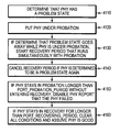
- the PHY is put under probation (step 4120 ). If the problem state is determined to go away while the PHY is under probation, a recovery period for recovery is started that runs simultaneously with probation (step 4130 ). The recovery period is cancelled if the PHY is determined to be in a problem state again (step 4140 ). If the PHY stays in probation longer than a PORT_PROBATION_PERIOD time without entering recovery, the PHY is disabled and it is reported that the PHY failed (step 4150 ). If the PHY stays in recovery for longer than a PORT_RECOVERING_PERIOD time, all conditions are cleared and it is assumed that the PHY is good (step 4160 ).
- PHYs that have been disabled are re-enabled when the cable is disconnected (or, in the case of a drive port, when the drive is removed).
- PORT_PROBATION_PERIOD is set to 5 seconds and PORT_RECOVERING_PERIOD is set to 2 seconds. These settings can be adjusted depending on the type of PHY (e.g., for cable or drive, or for wide port or drive port).
- the example implementation also has the following other characteristics as used herein. “Enabled” and “disabled” refers to an expander-controlled state of the PHY, i.e., whether it is turned on or off. “Reserved” and “unreserved” refers to the state of a PHY controlled by the expander, indicating whether the PHY is being used by a diagnostic procedure (e.g., a loopback test). “Ready” and “unready” refers to the status of the PHY as observed by an expander.
- a PHY is determined to be in a problem state in either of the following circumstances, and only in the case of a transient state of an enabled, unreserved PHY, which transient state is tested and then reset every poll cycle:
- a PHY is not ready when it should be ready. “Should be ready” refers to a case in which either a PHY is in a wide port that has ready unreserved PHYs, or a PHY is associated with a drive port and the corresponding insert bit is set.
- a disabled or reserved PHY may never be determined to be in a problem state.
- Port in the case of a drive PHY, corresponds to the PHY, and in the case of a wide port PHY, corresponds to all the PHYs in the wide port.
- Degraded refers to a state of a port in which at least one PHY in the port is in a problem state.
- Probation refers to a state of a port; each time this state is set, a probation timer starts.
- Recovery refers to a state of a port; it can be concurrent with probation, and each time this state is set, a recovery timer starts.
- the first example approach to the technique proceeds as follows. A check is made for any one of the following conditions on every poll cycle:
- this approach may be executed within device 66 a by logic 1106 with respect to one or more of PHYs 1102 , 1104 .
- this approach is useful for the implementation to be primitive, predictable, and independent of higher level code, and to take care of the case in which leaving the PHY enabled is detrimental to devices other than the device attached to the PHY in question.
- issues with the device attached to the PHY in question can be handled by other procedures, e.g., existing procedures within the system's operating system so that the device can be marked dead and the system can cease sending I/O to the device.
- a PHY can cause problems accessing other devices, particularly as a result of PHY state changes. Every time the PHY state changes, a broadcast is issued and a discovery is required. If this is happening frequently, it affects performance, fills logs, and in general make the system unhealthy. A way to detect when a PHY has caused a condition that triggered a broadcast is to look at its change count.
- the following pseudocode illustrates a sample embodiment of a procedure in accordance with the second example approach to the technique for use in managing SAS topology.
- the procedure may be summarized as follows.
- Each second it is determined whether the PHY ran clean in the last second (step 5110 ), “clean” meaning without one or more events that cause perturbation of the topology (e.g., a BROADCAST(CHANGE) event). If the PHY ran clean, a count is decremented; otherwise, the count is incremented (step 5120 ). If the count exceeds a PHY_PERTURB_THRESHOLD threshold, the PHY is disabled (step 5130 ). The PHY is only re-enabled at drive re-insert (and/or at drive removal), reboot of the expander or when commanded by the system, e.g., the operating system (step 5140 ).
Abstract
Description
-
- for phy in phys
- phy.ReEnable( )
- for phy in phys
-
- phy.ReEnable( )
-
- phy.ReEnable( )
-
- DisablePhy(phy.phyNumber)// Disable the physical phy
| RunOncePerSecond( ) | |
| { | |
| for phy in phys | |
| { | |
| if (phy.Enabled) | |
| { | |
| if (phy.lastChangeCount != GetPhyChangeCount(phy.phyNumber)) | |
| { | |
| phy.lastChangeCount = GetPhyChangeCount(phy.phyNumber); | |
| if (phy.perturbCount >= PHY_PERTURB_THRESHOLD) | |
| DisablePhy(phy.phyNumber) // Disable the physical phy | |
| phy.perturbCount = PHY_PERTURB_THRESHOLD; | |
| else | |
| phy.perturbCount += CLEAN_TO_DIRTY_RATIO; | |
| else if (phy.perturbCount >0) | |
| { // Phy ran clean this last second so reduce the perturb count | |
| phy.perturbCount--; | |
| } | |
| } | |
| } | |
| } | |
| phy.ReEnable( ) | |
| { | |
| // Clear the phy's perturb count before re-enabling the phy. | |
| self.perturbCount = 0; | |
| EnablePhy(self.PhyNumber) // Enable the physical phy | |
| } | |
Claims (11)
Priority Applications (1)
| Application Number | Priority Date | Filing Date | Title |
|---|---|---|---|
| US12/004,167 US7912995B1 (en) | 2007-12-20 | 2007-12-20 | Managing SAS topology |
Applications Claiming Priority (1)
| Application Number | Priority Date | Filing Date | Title |
|---|---|---|---|
| US12/004,167 US7912995B1 (en) | 2007-12-20 | 2007-12-20 | Managing SAS topology |
Publications (1)
| Publication Number | Publication Date |
|---|---|
| US7912995B1 true US7912995B1 (en) | 2011-03-22 |
Family
ID=43741881
Family Applications (1)
| Application Number | Title | Priority Date | Filing Date |
|---|---|---|---|
| US12/004,167 Active 2028-04-27 US7912995B1 (en) | 2007-12-20 | 2007-12-20 | Managing SAS topology |
Country Status (1)
| Country | Link |
|---|---|
| US (1) | US7912995B1 (en) |
Cited By (10)
| Publication number | Priority date | Publication date | Assignee | Title |
|---|---|---|---|---|
| US20130315058A1 (en) * | 2012-05-28 | 2013-11-28 | Fujitsu Limited | Relay device, connection management method, and information communication system |
| US8775876B2 (en) | 2011-11-22 | 2014-07-08 | Lsi Corporation | Method to improve I/O reliability on a degraded wide port connection |
| US9037910B2 (en) * | 2012-07-30 | 2015-05-19 | Hewlett-Packard Development Company, L.P. | SAS self-test operations |
| US9143432B2 (en) | 2012-04-10 | 2015-09-22 | Hewlett-Packard Development Company, L.P. | Expander-targeted zoned broadcast |
| US10425333B2 (en) | 2017-05-19 | 2019-09-24 | Western Digital Technologies, Inc. | Managing phys of a data storage target device |
| US10565041B2 (en) | 2017-05-19 | 2020-02-18 | Western Digital Technologies, Inc. | Managing phys of a data storage target device |
| US10635154B2 (en) | 2016-12-19 | 2020-04-28 | Western Digital Technologies, Inc. | Intelligent SAS phy power management |
| US11200132B1 (en) * | 2020-10-29 | 2021-12-14 | EMC IP Holding Company LLC | Anomaly aware log retrieval from disk array enclosures (DAEs) |
| US11226747B2 (en) | 2015-02-25 | 2022-01-18 | Western Digital Technologies, Inc. | System and method for copy on write on an SSD |
| US20230161727A1 (en) * | 2021-05-17 | 2023-05-25 | Gowin Semiconductor Corporation | Method and apparatus for providing a bridging device for interfacing between d-phy and c-phy |
Citations (11)
| Publication number | Priority date | Publication date | Assignee | Title |
|---|---|---|---|---|
| US7292597B2 (en) * | 2000-09-28 | 2007-11-06 | Teridian Semiconductor Corp. | Method and apparatus for transparent implementation of link-suspend capabilities in network devices |
| US20070294572A1 (en) * | 2006-06-08 | 2007-12-20 | Dot Hill Systems Corporation | Adaptive sas phy configuration |
| US7317732B2 (en) * | 2000-09-28 | 2008-01-08 | Teridian Semiconductor, Corp. | Method and apparatus for handling link suspend pulse and silent line state transitions of a network device |
| US7317691B2 (en) * | 2000-09-28 | 2008-01-08 | Teridian Semiconductor, Corp. | Method for initializing a link suspend device for optimum receive recovery |
| US7327754B2 (en) * | 2000-09-28 | 2008-02-05 | Teridian Semiconductor, Corp. | Apparatus and method for freezing the states of a receiver during silent line state operation of a network device |
| US20080056424A1 (en) * | 2006-09-01 | 2008-03-06 | Naichih Chang | Signal noise filtering in a serial interface |
| US7536584B2 (en) * | 2006-06-08 | 2009-05-19 | Dot Hill Systems Corporation | Fault-isolating SAS expander |
| US7584319B1 (en) * | 2005-03-31 | 2009-09-01 | Pmc-Sierra, Inc. | Connection management in serial attached SCSI (SAS) expanders |
| US7685329B1 (en) * | 2007-08-10 | 2010-03-23 | American Megatreads, Inc. | Detecting the presence and activity of a mass storage device |
| US7822908B2 (en) * | 2006-12-22 | 2010-10-26 | Lsi Corporation | Discovery of a bridge device in a SAS communication system |
| US7826349B2 (en) * | 2006-05-30 | 2010-11-02 | Intel Corporation | Connection management mechanism |
-
2007
- 2007-12-20 US US12/004,167 patent/US7912995B1/en active Active
Patent Citations (11)
| Publication number | Priority date | Publication date | Assignee | Title |
|---|---|---|---|---|
| US7292597B2 (en) * | 2000-09-28 | 2007-11-06 | Teridian Semiconductor Corp. | Method and apparatus for transparent implementation of link-suspend capabilities in network devices |
| US7317732B2 (en) * | 2000-09-28 | 2008-01-08 | Teridian Semiconductor, Corp. | Method and apparatus for handling link suspend pulse and silent line state transitions of a network device |
| US7317691B2 (en) * | 2000-09-28 | 2008-01-08 | Teridian Semiconductor, Corp. | Method for initializing a link suspend device for optimum receive recovery |
| US7327754B2 (en) * | 2000-09-28 | 2008-02-05 | Teridian Semiconductor, Corp. | Apparatus and method for freezing the states of a receiver during silent line state operation of a network device |
| US7584319B1 (en) * | 2005-03-31 | 2009-09-01 | Pmc-Sierra, Inc. | Connection management in serial attached SCSI (SAS) expanders |
| US7826349B2 (en) * | 2006-05-30 | 2010-11-02 | Intel Corporation | Connection management mechanism |
| US20070294572A1 (en) * | 2006-06-08 | 2007-12-20 | Dot Hill Systems Corporation | Adaptive sas phy configuration |
| US7536584B2 (en) * | 2006-06-08 | 2009-05-19 | Dot Hill Systems Corporation | Fault-isolating SAS expander |
| US20080056424A1 (en) * | 2006-09-01 | 2008-03-06 | Naichih Chang | Signal noise filtering in a serial interface |
| US7822908B2 (en) * | 2006-12-22 | 2010-10-26 | Lsi Corporation | Discovery of a bridge device in a SAS communication system |
| US7685329B1 (en) * | 2007-08-10 | 2010-03-23 | American Megatreads, Inc. | Detecting the presence and activity of a mass storage device |
Cited By (14)
| Publication number | Priority date | Publication date | Assignee | Title |
|---|---|---|---|---|
| US8775876B2 (en) | 2011-11-22 | 2014-07-08 | Lsi Corporation | Method to improve I/O reliability on a degraded wide port connection |
| US9143432B2 (en) | 2012-04-10 | 2015-09-22 | Hewlett-Packard Development Company, L.P. | Expander-targeted zoned broadcast |
| US20130315058A1 (en) * | 2012-05-28 | 2013-11-28 | Fujitsu Limited | Relay device, connection management method, and information communication system |
| US9037910B2 (en) * | 2012-07-30 | 2015-05-19 | Hewlett-Packard Development Company, L.P. | SAS self-test operations |
| US11226747B2 (en) | 2015-02-25 | 2022-01-18 | Western Digital Technologies, Inc. | System and method for copy on write on an SSD |
| US10635154B2 (en) | 2016-12-19 | 2020-04-28 | Western Digital Technologies, Inc. | Intelligent SAS phy power management |
| US10565041B2 (en) | 2017-05-19 | 2020-02-18 | Western Digital Technologies, Inc. | Managing phys of a data storage target device |
| US10785154B2 (en) | 2017-05-19 | 2020-09-22 | Western Digital Technologies, Inc. | Managing phys of a data storage target device |
| US10922160B2 (en) | 2017-05-19 | 2021-02-16 | Western Digital Technologies, Inc. | Managing phys of a data storage target device background of the disclosure |
| US10425333B2 (en) | 2017-05-19 | 2019-09-24 | Western Digital Technologies, Inc. | Managing phys of a data storage target device |
| US11200132B1 (en) * | 2020-10-29 | 2021-12-14 | EMC IP Holding Company LLC | Anomaly aware log retrieval from disk array enclosures (DAEs) |
| US20220138072A1 (en) * | 2020-10-29 | 2022-05-05 | EMC IP Holding Company LLC | ANOMALY AWARE LOG RETRIEVAL FROM DISK ARRAY ENCLOSURES (DAEs) |
| US11513931B2 (en) * | 2020-10-29 | 2022-11-29 | EMC IP Holding Company LLC | Anomaly aware log retrieval from disk array enclosures (DAEs) |
| US20230161727A1 (en) * | 2021-05-17 | 2023-05-25 | Gowin Semiconductor Corporation | Method and apparatus for providing a bridging device for interfacing between d-phy and c-phy |
Similar Documents
| Publication | Publication Date | Title |
|---|---|---|
| US7912995B1 (en) | Managing SAS topology | |
| US8458527B2 (en) | Method and apparatus for SAS speed adjustment | |
| US7536584B2 (en) | Fault-isolating SAS expander | |
| US8812913B2 (en) | Method and apparatus for isolating storage devices to facilitate reliable communication | |
| US8443237B2 (en) | Storage apparatus and method for controlling the same using loopback diagnosis to detect failure | |
| US8510606B2 (en) | Method and apparatus for SAS speed adjustment | |
| US7738366B2 (en) | Methods and structure for detecting SAS link errors with minimal impact on SAS initiator and link bandwidth | |
| EP2052326B1 (en) | Fault-isolating sas expander | |
| CN106603265B (en) | Management method, network device, and non-transitory computer-readable medium | |
| US8074105B2 (en) | High data availability SAS-based RAID system | |
| US7673185B2 (en) | Adaptive SAS PHY configuration | |
| US6892311B2 (en) | System and method for shutting down a host and storage enclosure if the status of the storage enclosure is in a first condition and is determined that the storage enclosure includes a critical storage volume | |
| US8667337B2 (en) | Storage apparatus and method of controlling the same | |
| US7565474B2 (en) | Computer system using serial connect bus, and method for interconnecting a plurality of CPU using serial connect bus | |
| US7568119B2 (en) | Storage control device and storage control device path switching method | |
| US7890794B1 (en) | Handling SAS topology problems | |
| JP2006072717A (en) | Disk subsystem | |
| CN107294759B (en) | Server system and data access method | |
| US8090881B1 (en) | Method and system for minimizing unnecessary topology discovery operations by managing physical layer state change notifications in storage systems | |
| US20040162928A1 (en) | High speed multiple ported bus interface reset control system | |
| US20040168008A1 (en) | High speed multiple ported bus interface port state identification system | |
| CN219695411U (en) | High-speed cable grafting detection device that targets in place | |
| US7627774B2 (en) | Redundant manager modules to perform management tasks with respect to an interconnect structure and power supplies | |
| US7486083B2 (en) | Managing system stability | |
| US20040162927A1 (en) | High speed multiple port data bus interface architecture |
Legal Events
| Date | Code | Title | Description |
|---|---|---|---|
| AS | Assignment |
Owner name: EMC CORPORATION, MASSACHUSETTS Free format text: ASSIGNMENT OF ASSIGNORS INTEREST;ASSIGNORS:LONG, MATTHEW;GASSER, MORRIE;PARRY, BRIAN;SIGNING DATES FROM 20071217 TO 20071219;REEL/FRAME:020340/0475 |
|
| STCF | Information on status: patent grant |
Free format text: PATENTED CASE |
|
| FPAY | Fee payment |
Year of fee payment: 4 |
|
| AS | Assignment |
Owner name: CREDIT SUISSE AG, CAYMAN ISLANDS BRANCH, AS COLLATERAL AGENT, NORTH CAROLINA Free format text: SECURITY AGREEMENT;ASSIGNORS:ASAP SOFTWARE EXPRESS, INC.;AVENTAIL LLC;CREDANT TECHNOLOGIES, INC.;AND OTHERS;REEL/FRAME:040134/0001 Effective date: 20160907 Owner name: THE BANK OF NEW YORK MELLON TRUST COMPANY, N.A., AS NOTES COLLATERAL AGENT, TEXAS Free format text: SECURITY AGREEMENT;ASSIGNORS:ASAP SOFTWARE EXPRESS, INC.;AVENTAIL LLC;CREDANT TECHNOLOGIES, INC.;AND OTHERS;REEL/FRAME:040136/0001 Effective date: 20160907 Owner name: CREDIT SUISSE AG, CAYMAN ISLANDS BRANCH, AS COLLAT Free format text: SECURITY AGREEMENT;ASSIGNORS:ASAP SOFTWARE EXPRESS, INC.;AVENTAIL LLC;CREDANT TECHNOLOGIES, INC.;AND OTHERS;REEL/FRAME:040134/0001 Effective date: 20160907 Owner name: THE BANK OF NEW YORK MELLON TRUST COMPANY, N.A., A Free format text: SECURITY AGREEMENT;ASSIGNORS:ASAP SOFTWARE EXPRESS, INC.;AVENTAIL LLC;CREDANT TECHNOLOGIES, INC.;AND OTHERS;REEL/FRAME:040136/0001 Effective date: 20160907 |
|
| AS | Assignment |
Owner name: EMC IP HOLDING COMPANY LLC, MASSACHUSETTS Free format text: ASSIGNMENT OF ASSIGNORS INTEREST;ASSIGNOR:EMC CORPORATION;REEL/FRAME:040203/0001 Effective date: 20160906 |
|
| MAFP | Maintenance fee payment |
Free format text: PAYMENT OF MAINTENANCE FEE, 8TH YEAR, LARGE ENTITY (ORIGINAL EVENT CODE: M1552); ENTITY STATUS OF PATENT OWNER: LARGE ENTITY Year of fee payment: 8 |
|
| AS | Assignment |
Owner name: THE BANK OF NEW YORK MELLON TRUST COMPANY, N.A., T Free format text: SECURITY AGREEMENT;ASSIGNORS:CREDANT TECHNOLOGIES, INC.;DELL INTERNATIONAL L.L.C.;DELL MARKETING L.P.;AND OTHERS;REEL/FRAME:049452/0223 Effective date: 20190320 Owner name: THE BANK OF NEW YORK MELLON TRUST COMPANY, N.A., TEXAS Free format text: SECURITY AGREEMENT;ASSIGNORS:CREDANT TECHNOLOGIES, INC.;DELL INTERNATIONAL L.L.C.;DELL MARKETING L.P.;AND OTHERS;REEL/FRAME:049452/0223 Effective date: 20190320 |
|
| AS | Assignment |
Owner name: THE BANK OF NEW YORK MELLON TRUST COMPANY, N.A., TEXAS Free format text: SECURITY AGREEMENT;ASSIGNORS:CREDANT TECHNOLOGIES INC.;DELL INTERNATIONAL L.L.C.;DELL MARKETING L.P.;AND OTHERS;REEL/FRAME:053546/0001 Effective date: 20200409 |
|
| AS | Assignment |
Owner name: WYSE TECHNOLOGY L.L.C., CALIFORNIA Free format text: RELEASE BY SECURED PARTY;ASSIGNOR:CREDIT SUISSE AG, CAYMAN ISLANDS BRANCH;REEL/FRAME:058216/0001 Effective date: 20211101 Owner name: SCALEIO LLC, MASSACHUSETTS Free format text: RELEASE BY SECURED PARTY;ASSIGNOR:CREDIT SUISSE AG, CAYMAN ISLANDS BRANCH;REEL/FRAME:058216/0001 Effective date: 20211101 Owner name: MOZY, INC., WASHINGTON Free format text: RELEASE BY SECURED PARTY;ASSIGNOR:CREDIT SUISSE AG, CAYMAN ISLANDS BRANCH;REEL/FRAME:058216/0001 Effective date: 20211101 Owner name: MAGINATICS LLC, CALIFORNIA Free format text: RELEASE BY SECURED PARTY;ASSIGNOR:CREDIT SUISSE AG, CAYMAN ISLANDS BRANCH;REEL/FRAME:058216/0001 Effective date: 20211101 Owner name: FORCE10 NETWORKS, INC., CALIFORNIA Free format text: RELEASE BY SECURED PARTY;ASSIGNOR:CREDIT SUISSE AG, CAYMAN ISLANDS BRANCH;REEL/FRAME:058216/0001 Effective date: 20211101 Owner name: EMC IP HOLDING COMPANY LLC, TEXAS Free format text: RELEASE BY SECURED PARTY;ASSIGNOR:CREDIT SUISSE AG, CAYMAN ISLANDS BRANCH;REEL/FRAME:058216/0001 Effective date: 20211101 Owner name: EMC CORPORATION, MASSACHUSETTS Free format text: RELEASE BY SECURED PARTY;ASSIGNOR:CREDIT SUISSE AG, CAYMAN ISLANDS BRANCH;REEL/FRAME:058216/0001 Effective date: 20211101 Owner name: DELL SYSTEMS CORPORATION, TEXAS Free format text: RELEASE BY SECURED PARTY;ASSIGNOR:CREDIT SUISSE AG, CAYMAN ISLANDS BRANCH;REEL/FRAME:058216/0001 Effective date: 20211101 Owner name: DELL SOFTWARE INC., CALIFORNIA Free format text: RELEASE BY SECURED PARTY;ASSIGNOR:CREDIT SUISSE AG, CAYMAN ISLANDS BRANCH;REEL/FRAME:058216/0001 Effective date: 20211101 Owner name: DELL PRODUCTS L.P., TEXAS Free format text: RELEASE BY SECURED PARTY;ASSIGNOR:CREDIT SUISSE AG, CAYMAN ISLANDS BRANCH;REEL/FRAME:058216/0001 Effective date: 20211101 Owner name: DELL MARKETING L.P., TEXAS Free format text: RELEASE BY SECURED PARTY;ASSIGNOR:CREDIT SUISSE AG, CAYMAN ISLANDS BRANCH;REEL/FRAME:058216/0001 Effective date: 20211101 Owner name: DELL INTERNATIONAL, L.L.C., TEXAS Free format text: RELEASE BY SECURED PARTY;ASSIGNOR:CREDIT SUISSE AG, CAYMAN ISLANDS BRANCH;REEL/FRAME:058216/0001 Effective date: 20211101 Owner name: DELL USA L.P., TEXAS Free format text: RELEASE BY SECURED PARTY;ASSIGNOR:CREDIT SUISSE AG, CAYMAN ISLANDS BRANCH;REEL/FRAME:058216/0001 Effective date: 20211101 Owner name: CREDANT TECHNOLOGIES, INC., TEXAS Free format text: RELEASE BY SECURED PARTY;ASSIGNOR:CREDIT SUISSE AG, CAYMAN ISLANDS BRANCH;REEL/FRAME:058216/0001 Effective date: 20211101 Owner name: AVENTAIL LLC, CALIFORNIA Free format text: RELEASE BY SECURED PARTY;ASSIGNOR:CREDIT SUISSE AG, CAYMAN ISLANDS BRANCH;REEL/FRAME:058216/0001 Effective date: 20211101 Owner name: ASAP SOFTWARE EXPRESS, INC., ILLINOIS Free format text: RELEASE BY SECURED PARTY;ASSIGNOR:CREDIT SUISSE AG, CAYMAN ISLANDS BRANCH;REEL/FRAME:058216/0001 Effective date: 20211101 |
|
| AS | Assignment |
Owner name: SCALEIO LLC, MASSACHUSETTS Free format text: RELEASE OF SECURITY INTEREST IN PATENTS PREVIOUSLY RECORDED AT REEL/FRAME (040136/0001);ASSIGNOR:THE BANK OF NEW YORK MELLON TRUST COMPANY, N.A., AS NOTES COLLATERAL AGENT;REEL/FRAME:061324/0001 Effective date: 20220329 Owner name: EMC IP HOLDING COMPANY LLC (ON BEHALF OF ITSELF AND AS SUCCESSOR-IN-INTEREST TO MOZY, INC.), TEXAS Free format text: RELEASE OF SECURITY INTEREST IN PATENTS PREVIOUSLY RECORDED AT REEL/FRAME (040136/0001);ASSIGNOR:THE BANK OF NEW YORK MELLON TRUST COMPANY, N.A., AS NOTES COLLATERAL AGENT;REEL/FRAME:061324/0001 Effective date: 20220329 Owner name: EMC CORPORATION (ON BEHALF OF ITSELF AND AS SUCCESSOR-IN-INTEREST TO MAGINATICS LLC), MASSACHUSETTS Free format text: RELEASE OF SECURITY INTEREST IN PATENTS PREVIOUSLY RECORDED AT REEL/FRAME (040136/0001);ASSIGNOR:THE BANK OF NEW YORK MELLON TRUST COMPANY, N.A., AS NOTES COLLATERAL AGENT;REEL/FRAME:061324/0001 Effective date: 20220329 Owner name: DELL MARKETING CORPORATION (SUCCESSOR-IN-INTEREST TO FORCE10 NETWORKS, INC. AND WYSE TECHNOLOGY L.L.C.), TEXAS Free format text: RELEASE OF SECURITY INTEREST IN PATENTS PREVIOUSLY RECORDED AT REEL/FRAME (040136/0001);ASSIGNOR:THE BANK OF NEW YORK MELLON TRUST COMPANY, N.A., AS NOTES COLLATERAL AGENT;REEL/FRAME:061324/0001 Effective date: 20220329 Owner name: DELL PRODUCTS L.P., TEXAS Free format text: RELEASE OF SECURITY INTEREST IN PATENTS PREVIOUSLY RECORDED AT REEL/FRAME (040136/0001);ASSIGNOR:THE BANK OF NEW YORK MELLON TRUST COMPANY, N.A., AS NOTES COLLATERAL AGENT;REEL/FRAME:061324/0001 Effective date: 20220329 Owner name: DELL INTERNATIONAL L.L.C., TEXAS Free format text: RELEASE OF SECURITY INTEREST IN PATENTS PREVIOUSLY RECORDED AT REEL/FRAME (040136/0001);ASSIGNOR:THE BANK OF NEW YORK MELLON TRUST COMPANY, N.A., AS NOTES COLLATERAL AGENT;REEL/FRAME:061324/0001 Effective date: 20220329 Owner name: DELL USA L.P., TEXAS Free format text: RELEASE OF SECURITY INTEREST IN PATENTS PREVIOUSLY RECORDED AT REEL/FRAME (040136/0001);ASSIGNOR:THE BANK OF NEW YORK MELLON TRUST COMPANY, N.A., AS NOTES COLLATERAL AGENT;REEL/FRAME:061324/0001 Effective date: 20220329 Owner name: DELL MARKETING L.P. (ON BEHALF OF ITSELF AND AS SUCCESSOR-IN-INTEREST TO CREDANT TECHNOLOGIES, INC.), TEXAS Free format text: RELEASE OF SECURITY INTEREST IN PATENTS PREVIOUSLY RECORDED AT REEL/FRAME (040136/0001);ASSIGNOR:THE BANK OF NEW YORK MELLON TRUST COMPANY, N.A., AS NOTES COLLATERAL AGENT;REEL/FRAME:061324/0001 Effective date: 20220329 Owner name: DELL MARKETING CORPORATION (SUCCESSOR-IN-INTEREST TO ASAP SOFTWARE EXPRESS, INC.), TEXAS Free format text: RELEASE OF SECURITY INTEREST IN PATENTS PREVIOUSLY RECORDED AT REEL/FRAME (040136/0001);ASSIGNOR:THE BANK OF NEW YORK MELLON TRUST COMPANY, N.A., AS NOTES COLLATERAL AGENT;REEL/FRAME:061324/0001 Effective date: 20220329 |
|
| AS | Assignment |
Owner name: SCALEIO LLC, MASSACHUSETTS Free format text: RELEASE OF SECURITY INTEREST IN PATENTS PREVIOUSLY RECORDED AT REEL/FRAME (045455/0001);ASSIGNOR:THE BANK OF NEW YORK MELLON TRUST COMPANY, N.A., AS NOTES COLLATERAL AGENT;REEL/FRAME:061753/0001 Effective date: 20220329 Owner name: EMC IP HOLDING COMPANY LLC (ON BEHALF OF ITSELF AND AS SUCCESSOR-IN-INTEREST TO MOZY, INC.), TEXAS Free format text: RELEASE OF SECURITY INTEREST IN PATENTS PREVIOUSLY RECORDED AT REEL/FRAME (045455/0001);ASSIGNOR:THE BANK OF NEW YORK MELLON TRUST COMPANY, N.A., AS NOTES COLLATERAL AGENT;REEL/FRAME:061753/0001 Effective date: 20220329 Owner name: EMC CORPORATION (ON BEHALF OF ITSELF AND AS SUCCESSOR-IN-INTEREST TO MAGINATICS LLC), MASSACHUSETTS Free format text: RELEASE OF SECURITY INTEREST IN PATENTS PREVIOUSLY RECORDED AT REEL/FRAME (045455/0001);ASSIGNOR:THE BANK OF NEW YORK MELLON TRUST COMPANY, N.A., AS NOTES COLLATERAL AGENT;REEL/FRAME:061753/0001 Effective date: 20220329 Owner name: DELL MARKETING CORPORATION (SUCCESSOR-IN-INTEREST TO FORCE10 NETWORKS, INC. AND WYSE TECHNOLOGY L.L.C.), TEXAS Free format text: RELEASE OF SECURITY INTEREST IN PATENTS PREVIOUSLY RECORDED AT REEL/FRAME (045455/0001);ASSIGNOR:THE BANK OF NEW YORK MELLON TRUST COMPANY, N.A., AS NOTES COLLATERAL AGENT;REEL/FRAME:061753/0001 Effective date: 20220329 Owner name: DELL PRODUCTS L.P., TEXAS Free format text: RELEASE OF SECURITY INTEREST IN PATENTS PREVIOUSLY RECORDED AT REEL/FRAME (045455/0001);ASSIGNOR:THE BANK OF NEW YORK MELLON TRUST COMPANY, N.A., AS NOTES COLLATERAL AGENT;REEL/FRAME:061753/0001 Effective date: 20220329 Owner name: DELL INTERNATIONAL L.L.C., TEXAS Free format text: RELEASE OF SECURITY INTEREST IN PATENTS PREVIOUSLY RECORDED AT REEL/FRAME (045455/0001);ASSIGNOR:THE BANK OF NEW YORK MELLON TRUST COMPANY, N.A., AS NOTES COLLATERAL AGENT;REEL/FRAME:061753/0001 Effective date: 20220329 Owner name: DELL USA L.P., TEXAS Free format text: RELEASE OF SECURITY INTEREST IN PATENTS PREVIOUSLY RECORDED AT REEL/FRAME (045455/0001);ASSIGNOR:THE BANK OF NEW YORK MELLON TRUST COMPANY, N.A., AS NOTES COLLATERAL AGENT;REEL/FRAME:061753/0001 Effective date: 20220329 Owner name: DELL MARKETING L.P. (ON BEHALF OF ITSELF AND AS SUCCESSOR-IN-INTEREST TO CREDANT TECHNOLOGIES, INC.), TEXAS Free format text: RELEASE OF SECURITY INTEREST IN PATENTS PREVIOUSLY RECORDED AT REEL/FRAME (045455/0001);ASSIGNOR:THE BANK OF NEW YORK MELLON TRUST COMPANY, N.A., AS NOTES COLLATERAL AGENT;REEL/FRAME:061753/0001 Effective date: 20220329 Owner name: DELL MARKETING CORPORATION (SUCCESSOR-IN-INTEREST TO ASAP SOFTWARE EXPRESS, INC.), TEXAS Free format text: RELEASE OF SECURITY INTEREST IN PATENTS PREVIOUSLY RECORDED AT REEL/FRAME (045455/0001);ASSIGNOR:THE BANK OF NEW YORK MELLON TRUST COMPANY, N.A., AS NOTES COLLATERAL AGENT;REEL/FRAME:061753/0001 Effective date: 20220329 |
|
| MAFP | Maintenance fee payment |
Free format text: PAYMENT OF MAINTENANCE FEE, 12TH YEAR, LARGE ENTITY (ORIGINAL EVENT CODE: M1553); ENTITY STATUS OF PATENT OWNER: LARGE ENTITY Year of fee payment: 12 |