US7913890B2 - Multistage solenoid fastening device - Google Patents
Multistage solenoid fastening device Download PDFInfo
- Publication number
- US7913890B2 US7913890B2 US12/689,077 US68907710A US7913890B2 US 7913890 B2 US7913890 B2 US 7913890B2 US 68907710 A US68907710 A US 68907710A US 7913890 B2 US7913890 B2 US 7913890B2
- Authority
- US
- United States
- Prior art keywords
- stage
- control module
- armature member
- armature
- driver
- Prior art date
- Legal status (The legal status is an assumption and is not a legal conclusion. Google has not performed a legal analysis and makes no representation as to the accuracy of the status listed.)
- Active
Links
Images


Classifications
-
- B—PERFORMING OPERATIONS; TRANSPORTING
- B25—HAND TOOLS; PORTABLE POWER-DRIVEN TOOLS; MANIPULATORS
- B25C—HAND-HELD NAILING OR STAPLING TOOLS; MANUALLY OPERATED PORTABLE STAPLING TOOLS
- B25C1/00—Hand-held nailing tools; Nail feeding devices
- B25C1/06—Hand-held nailing tools; Nail feeding devices operated by electric power
Definitions
- the present teachings relate to a cordless fastening tool and more specifically relate to a multistage solenoid that can extend and retract a driver blade of the cordless fastening tool and adjust the magnetic fields of each of the stages of the multistage solenoid based on a position of the armature within the multistage solenoid.
- Traditional fastening tools can employ pneumatic actuation to drive a fastener into a workpiece.
- air pressure from a pneumatic system can be utilized to both drive the fastener into the workpiece and to reset the tool after driving the fastener.
- a hose and a compressor are required to accompany the tool.
- a combination of the hose, the tool and the compressor can provide for a large, heavy and bulky package that can be relatively inconvenient and cumbersome to transport.
- Other traditional fastening tools can be battery powered and can engage a transmission and a motor to drive a fastener. Inefficiencies inherent in the transmission and the motor, however, can limit battery life.
- a solenoid has been used in fastening tools to drive fasteners.
- the solenoid executes multiple impacts on a single fastener to generate the force needed to drive the fastener into a workpiece.
- corded tools can use a solenoid to drive the fastener but the energy requirements can be relatively large and are better suited to corded applications.
- the present teachings generally include a device including a multistage solenoid having at least a first stage, a second stage and an armature member that travels therebetween.
- the device also includes a control module connected to the multistage solenoid.
- the control module detects a position of the armature member relative to at least one of the first stage, the second stage and a combination thereof.
- the control module adjusts a magnetic field of the at least one of the first stage, the second stage and the combination thereof based on the position of the plunger armature relative thereto.
- FIG. 1 is a perspective view of an exemplary cordless fastening tool having a multistage solenoid capable of inserting an exemplary fastener and an exemplary workpiece constructed in accordance with one aspect of the present teachings.
- FIGS. 2A , 2 B and 2 C are diagrams showing a progression of an exemplary driver sequence of a multistage solenoid that extends a portion of a driver assembly from a retracted condition to an extended condition constructed in accordance with one aspect of the present teachings.
- FIG. 3 is a diagram of a multistage solenoid having sensors that detect a position of a plunger relative to the stages constructed in accordance with one aspect of the present teachings.
- FIG. 4 is a diagram of a multistage solenoid having four stages constructed in accordance with one aspect of the present teachings.
- FIG. 5 is a diagram showing a spring member connected to a plunger of a multistage solenoid that returns the plunger to the retracted condition from the extended condition constructed in accordance with one aspect of the present teachings.
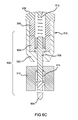
- FIGS. 6A , 6 B and 6 C are diagrams of a driver sequence of a multistage solenoid with a plunger having a return spring that extends to contact a separate driver blade that also has a return spring constructed in accordance with one aspect of the present teachings.
- FIG. 7 is a diagram of a value of current used by the multistage solenoid and shows an inflection point of the value of current associated with a stage in the multistage solenoid in accordance with one aspect of the present teachings.
- the value of current is shown as a function of voltage and time.
- FIG. 8 is a flowchart of an exemplary method of use of the multistage solenoid in a fastening tool in accordance with another aspect of the present teachings.
- module and/or control module can refer to an application specific integrated circuit (ASIC), an electronic circuit, a processor (shared, dedicated, or group) and memory that executes one or more software or firmware programs, a combinational logic circuit, other suitable components and/or one or more suitable combinations thereof that provide the described functionality.
- ASIC application specific integrated circuit
- processor shared, dedicated, or group
- memory that executes one or more software or firmware programs, a combinational logic circuit, other suitable components and/or one or more suitable combinations thereof that provide the described functionality.
- an exemplary fastening tool 10 can include a multistage solenoid 12 that can drive a driver assembly 14 between a retracted condition (as shown in FIG. 1 ) and an extended condition (see, e.g., FIG. 2C ) in accordance with one aspect of the present teachings.
- the fastening tool 10 can include an exterior housing 16 , which can house a first stage 18 and a second stage 20 of the multistage solenoid 12 .
- the exterior housing 16 can further contain the driver assembly 14 and a control module 22 .
- the multistage solenoid 12 is shown in FIG. 1 with the first stage 18 and the second stage 20 , the multistage solenoid 12 can include additional stages in suitable implementations, examples of which are later described herein.
- the exemplary fastening tool 10 can also include a nosepiece 24 , a fastener magazine 26 and a battery 28 .
- the fastener magazine 26 can be connected to the driver assembly 14
- the battery 28 can be coupled to the exterior housing 16 .
- the control module 22 can control the first stage 18 and the second stage 20 to magnetically move the driver assembly 14 so that a driver blade 30 can drive one or more fasteners 32 into a workpiece 34 that are sequentially fed from the fastener magazine 26 when a trigger assembly 36 is retracted.
- the fasteners 32 can be nails, staples, brads, clips or any such suitable fastener 32 that can be driven into the workpiece 34 .
- a multistage solenoid 100 can include a first stage 102 and a second stage 104 that can each include one or more coil assemblies that can be selectively energized to establish a magnetic field and de-energized to collapse the magnetic field in accordance with one aspect of the present teachings.
- the one or more magnetic fields can establish a generally linear motion of an armature member 106 that moves relative to the stages 102 , 104 .
- the magnetic fields can be selectively energized or collapsed to relatively efficiently drive the one or more fasteners 32 ( FIG. 1 ).
- the multistage solenoid 100 can save (i.e., not expend) the energy to maintain the magnetic fields by collapsing the magnetic fields at predetermined times and/or locations of the armature member 106 relative to stages 102 , 104 .
- the armature member 106 can define (wholly or partially) a plunger member 108 that can move from a retracted condition ( FIG. 2A ) to an extended condition ( FIG. 2C ).
- the driver assembly 14 can include the driver blade 30 that can be connected to a plunger member 108 a via a link member 38 .
- the plunger member 108 a can define (wholly or partially) an armature member 106 a associated with the multistage solenoid 12 .
- additional link members can connect the driver blade 30 to the plunger member 108 a or the plunger member 108 a can also be directly coupled to the driver blade 30 .
- the plunger member 108 can travel between a top stop 110 and a bottom stop 112 .
- a portion of the plunger member 108 can define a driver blade 120 , when applicable.
- the top stop 110 and/or the bottom stop 112 can be a portion of the stages 102 , 104 , an interior portion of the exterior housing 16 ( FIG. 1 ), a separate component connected to the interior portion of the exterior housing 16 and/or the stages 18 , 20 , and/or one or more combinations thereof.
- the driver blade 120 can extend beyond the bottom stop 112 .
- the driver assembly 14 can cycle through a driver sequence that can drive the fastener 32 into the workpiece 34 , as shown in FIG. 1 .
- the driver sequence can begin, for example, with the plunger member 108 in the retracted condition.
- the first stage 102 and the second stage 104 can be energized to establish the respective magnetic fields to draw the plunger member 108 a (i.e., the armature member 106 ) toward the second stage 104 .
- the plunger member 108 is connected to a driver blade 120
- the driver blade 120 can begin to move from a retracted condition to an extended condition.
- the plunger member 108 can end its motion at or near the bottom stop 112 .
- the first stage 102 and/or the second stage 104 can be energized but the direction of the magnetic field can be reversed so as to reverse the direction of the magnetic force applied to the plunger member 108 .
- the plunger member 108 a in FIG. 1 , can return the driver blade 30 to the retracted condition from the extended condition.
- the armature member 106 can further define a core member 124 that can be secured to the plunger member 108 with a cap member 122 .
- the cap member 122 and/or the core member 124 can be included, while in other aspects of the present teaching the cap member 122 and/or the core member 124 can be omitted.
- a position of the plunger member 108 (i.e., the armature member 106 ) can be determined relative to the stages 102 , 104 by detecting, for example, a change in current.
- the change in current can be caused by a change in inductance of one or more coil circuits in one or more coil assemblies that can be associated with one or more of the stages 102 , 104 .
- this change in inductance affects the resistance of the one or more coil circuits in the one or more coil assemblies, which can ultimately be measured as a change in current associated with a respective coil circuit.
- a diagram 150 shows a value of current 152 as a function of time and direct current voltage.
- a current inflection point 154 can be detected and can serve as a proxy for the position of the armature member 106 ( FIG. 2 ) in the multistage solenoid 100 ( FIG. 2 ).
- the control module 22 FIG. 1
- the control module 22 can direct full power from the first stage 102 ( FIG. 2 ) to the second stage 104 ( FIG. 2 ).
- the direction of full power between the stages based on the detection of the inflection point can be repeated as the armature member 106 travels between the stages.
- the control module 22 can direct full power to each stage and switch power between the stages based on the position of the armature member 106 without the need to modulate the power with, for example, pulse width modulation.
- the detection of the inflection point 154 can be based on detection of a threshold change of rate of a value of current.
- the control module 22 FIG. 1
- the inflection point can also define a point where the value of the change of rate of current, as illustrated in FIG. 7 , changes from a positive value to a negative value or vice versa, i.e., the concavity of the slope changes.
- control module 22 can specifically determine when the value of the rate of change of the value of current changes from a positive value to a negative value, as shown at the inflection point 154 . Put another way, the control module 22 detects the value of the second derivative of current of a period of time, such that when the value of the second derivative becomes negative, the control module can direct power to the subsequent stage.
- one or more sensors 200 can be used to detect the position of the armature member 106 relative to the stages 102 , 104 in the multistage solenoid 100 . In doing so, the position and/or velocity of the armature member 106 and the energizing and collapsing of magnetic fields of the stages 102 , 104 can be tuned (i.e., adjusted) to further conserve energy and/or increase a force produced by the multistage solenoid 100 .
- a multistage solenoid 300 can include more than two stages: a first stage 302 , a second stage 304 , a third stage 306 and a fourth stage 308 .
- a plunger member 310 i.e., an armature 312
- each of the stages 302 , 304 , 306 , 308 can be energized and de-energized in a cascading fashion.
- the plunger member 310 can be continuously accelerated toward the next stage (e.g., the second stage 304 to the third stage 306 ) until the travel of the plunger member 310 terminates in the extended condition and/or a portion of the plunger member 310 contacts a second stop 312 that resides on an opposite side of the multistage solenoid 300 from a first stop 314 .
- the plunger member 310 can define a driver blade 316 or can connect thereto in various suitable fashions.
- each of the stages 302 , 304 , 306 , 308 can be energized and then de-energized in a similar but reverse cascading fashion to draw the plunger member 310 from the extended condition back to the retracted condition, as shown in FIG. 4 .
- a spring or other suitable elastic member can also be used to move (partially or wholly) the plunger member 310 from the extended condition to the retracted condition, as discussed in greater detail below.
- a spring 400 or other suitable elastic member can be attached to a portion of a plunger member 402 .
- the spring 400 can hold the plunger member 402 in a retracted condition (see, e.g., FIG. 6A ) and, when applicable, urge the plunger member 402 to return to the retracted condition from an extended condition (see, e.g., FIG. 6B ).
- a first stage 404 and/or a second stage 406 of a multistage solenoid 408 when energized, can hold the plunger member 402 in the retracted condition.
- the spring 400 can, in combination with the first stage 404 and/or the second stage 406 (or by itself), also hold the plunger member 402 in the retracted condition.
- the spring 400 can be elongated and thus produce a spring force that can act to return the plunger member 402 to the retracted condition.
- the spring 400 can begin to pull the plunger member 402 toward a first stop 412 and into the retracted condition.
- the spring force generated by the spring 400 in the elongated condition can also draw the plunger member 402 back to the retracted condition.
- the plunger member 402 can define a driver blade 414 . It will be appreciated in light of the disclosure that the first stage 404 and/or the second stage 406 need not be used in lieu of using the spring 400 or other suitable elastic member to return the plunger member 402 back to the retracted condition. Because the first stage 404 and/or the second stage 406 need not be energized (or a field generated by the first stage 404 and/or the second stage 406 need not be as strong) to move the plunger member 402 to the retracted condition, battery life can be extended.
- a driver assembly 500 can include a two-piece assembly.
- the driver assembly 500 can include a plunger member 502 that can move independently of a driver blade member 504 .
- the plunger member 502 can be moved between an extended condition ( FIG. 6C ) and a retracted condition ( FIG. 6A ) by energizing and de-energizing at least a first stage 506 and/or a second stage 508 of a multistage solenoid 510 .
- the plunger member 502 when moved from the retracted condition to the extended condition by one or more of the stages 506 , 508 can strike and, therefore, impart a force on the driver blade member 504 .
- the force from the plunger member 502 can move the driver blade member 504 from a retracted condition ( FIG. 6A ) to an extended condition ( FIG. 6C ) to, for example, drive a fastener into a workpiece in a similar fashion to the driver blade 30 , as shown in FIG. 1 .
- a spring 512 or other elastic member can be attached to the plunger member 502 and a portion of a first stop 518 and can assist with the movement of the plunger member 502 from the extended condition ( FIG. 6C ) back to the retracted condition ( FIG. 6A ).
- a spring 514 or other suitable elastic member can be attached to the driver blade member 504 and a block member 516 .
- the block member 516 can be contained with a suitable tool housing. The spring 514 attached to the driver blade member 504 can move the driver blade member 504 from the extended condition ( FIG. 6C ) back to the retracted condition ( FIG. 6A ).
- the first stage 506 and/or the second stage 508 can be energized to draw the plunger member 502 from the retracted condition to the extended condition. As the plunger member 502 is drawn toward the second stage 508 , the plunger member 502 can strike the driver blade member 504 to move the driver blade member 504 from the retracted condition to the extended condition. It will be appreciated in light of this disclosure that the larger the velocity achieved by the plunger member 502 , the larger amount of energy (e.g., an impulsive force) that is delivered to the driver blade member 504 .
- energy e.g., an impulsive force
- the spring 514 or the suitable elastic member can pull the driver blade member 504 back to the retracted condition.
- the stages 506 , 508 can be energized to draw the plunger member 502 back to the retracted condition.
- the springs 512 , 514 or other suitable elastic member can (wholly or partially) draw the plunger member 502 and/or the driver blade member 504 back from the extended condition to the retracted condition.
- the two or more stages of the multistage solenoid can be energized in a cascading fashion to move a driver assembly that can have a driver blade in a similar fashion to an electric motor and a transmission.
- the multistage solenoid can be shown to provide relatively better battery life.
- the fastening tool using the multistage solenoid can provide a relatively lighter, more balanced and more compact tool.
- the nosepiece 22 can include a contact trip mechanism 50 as is known in the art.
- the contact trip mechanism 50 can be configured to prevent the fastening tool 10 from driving the fastener 32 into the workpiece 34 (e.g., inhibit power to the multistage solenoid) unless the contact trip mechanism 50 is in contact with the workpiece 34 (i.e., in a retracted position).
- an exemplary method is illustrated in a flow chart that can be used with the multistage solenoid 100 and, for example, the fastening tool 10 having the multistage solenoid 12 that drives the driver assembly 14 , as shown in FIG. 1 .
- the contact trip mechanism 50 ( FIG. 1 ) associated with the fastening tool 10 is engaged, e.g., retracted against the workpiece 34 ( FIG. 1 ).
- a user can retract the trigger assembly 36 .
- the control module 22 can direct power to the first stage 18 .
- the first stage is energized and can establish a magnetic field that can exert a force on the armature member 106 a ( FIG. 1 ).
- the control module 22 can monitor the value of the current over time to determine when a value of the current establishes an inflection point.
- the control module 22 can determine whether the value of current is indicative of a tool jam condition and/or a low battery condition. In one example, the value of current can be relatively higher when the tool jam condition and/or the low battery condition occur.
- the method continues at 620 .
- the method continues at 610 .
- the control module 22 ( FIG. 1 ) can determine whether the current inflection point has been detected. When the control module 22 detects the current inflection point, the method continues at 612 . When the control module 22 does not detect the current inflection point, the method continues at 620 . In 612 , the control module 22 can determine whether a threshold period of time has expired before the detection of the current inflection point. When the control module 22 detects the current inflection point before the expiration of the threshold period of time, the method continues at 614 . When the control module 22 detects the current inflection point after the expiration of the threshold period of time, the method continues at 620 .
- the control module 22 can shift power from the first stage 18 ( FIG. 1 ) to the second stage 20 ( FIG. 1 ) based on the detection of the first inflection point. It will be appreciated in light of the disclosure that in an instance where the multistage solenoid 12 ( FIG. 1 ) has more than two stages, the method can loop back to 606 and wait to detect a second inflection point. When the second inflection point is detected, the control module 22 can send power from the second stage to a third stage of the multistage solenoid. This can continue until power is sent to the last stage of the multistage solenoid 12 .
- the control module 22 can remove power from all of the stages, so that each stage is not applying a force to the armature member 106 a ( FIG. 1 ).
- a suitable return spring or other suitable mechanism can return the driver assembly 14 to the retracted condition, i.e., returning the armature member 106 a to the first stage 18 .
- the fields generated by the stages of the multistage solenoid 12 can be reversed to direct the armature member 106 a ( FIG. 1 ) in a direction opposite, as discussed above, to return the driver assembly 14 to the retracted or beginning condition.
- the control module 22 in 620 , can remove power from all of the stages, so that each stage does not apply a force to the armature member 106 a ( FIG. 1 ). From 618 and from 620 , the method ends.
Abstract
Description
Claims (20)
Priority Applications (1)
| Application Number | Priority Date | Filing Date | Title |
|---|---|---|---|
| US12/689,077 US7913890B2 (en) | 2007-02-01 | 2010-01-18 | Multistage solenoid fastening device |
Applications Claiming Priority (3)
| Application Number | Priority Date | Filing Date | Title |
|---|---|---|---|
| US11/670,088 US7537145B2 (en) | 2007-02-01 | 2007-02-01 | Multistage solenoid fastening device |
| US12/402,974 US7665540B2 (en) | 2007-02-01 | 2009-03-12 | Multistage solenoid fastening device |
| US12/689,077 US7913890B2 (en) | 2007-02-01 | 2010-01-18 | Multistage solenoid fastening device |
Related Parent Applications (1)
| Application Number | Title | Priority Date | Filing Date |
|---|---|---|---|
| US12/402,974 Division US7665540B2 (en) | 2007-02-01 | 2009-03-12 | Multistage solenoid fastening device |
Publications (2)
| Publication Number | Publication Date |
|---|---|
| US20100116866A1 US20100116866A1 (en) | 2010-05-13 |
| US7913890B2 true US7913890B2 (en) | 2011-03-29 |
Family
ID=39313081
Family Applications (3)
| Application Number | Title | Priority Date | Filing Date |
|---|---|---|---|
| US11/670,088 Active 2027-06-28 US7537145B2 (en) | 2007-02-01 | 2007-02-01 | Multistage solenoid fastening device |
| US12/402,974 Active US7665540B2 (en) | 2007-02-01 | 2009-03-12 | Multistage solenoid fastening device |
| US12/689,077 Active US7913890B2 (en) | 2007-02-01 | 2010-01-18 | Multistage solenoid fastening device |
Family Applications Before (2)
| Application Number | Title | Priority Date | Filing Date |
|---|---|---|---|
| US11/670,088 Active 2027-06-28 US7537145B2 (en) | 2007-02-01 | 2007-02-01 | Multistage solenoid fastening device |
| US12/402,974 Active US7665540B2 (en) | 2007-02-01 | 2009-03-12 | Multistage solenoid fastening device |
Country Status (4)
| Country | Link |
|---|---|
| US (3) | US7537145B2 (en) |
| EP (1) | EP1952949B1 (en) |
| JP (1) | JP5410680B2 (en) |
| TW (1) | TW200938341A (en) |
Cited By (9)
| Publication number | Priority date | Publication date | Assignee | Title |
|---|---|---|---|---|
| US10464197B2 (en) | 2012-06-28 | 2019-11-05 | Stanley Fastening Systems, L.P. | Carton closing tool having tool-free adjustment members |
| US10723005B2 (en) | 2018-03-28 | 2020-07-28 | Black & Decker Inc. | Electric fastener driving tool assembly including a driver home position sensor |
| US10933521B2 (en) | 2018-11-19 | 2021-03-02 | Brahma Industries LLC | Staple gun with self-centering mechanism |
| US10967492B2 (en) | 2018-11-19 | 2021-04-06 | Brahma Industries LLC | Staple gun with automatic depth adjustment |
| US11110577B2 (en) | 2017-11-16 | 2021-09-07 | Milwaukee Electric Tool Corporation | Pneumatic fastener driver |
| US11141849B2 (en) | 2018-11-19 | 2021-10-12 | Brahma Industries LLC | Protective shield for use with a staple gun |
| US20220072689A1 (en) * | 2018-12-20 | 2022-03-10 | Hilti Aktiengesellschaft | Driving-in device |
| US20230001555A1 (en) * | 2019-12-20 | 2023-01-05 | Hilti Aktiengesellschaft | Working tool |
| US11806854B2 (en) | 2019-02-19 | 2023-11-07 | Brahma Industries LLC | Insert for palm stapler, a palm stapler and a method of use thereof |
Families Citing this family (22)
| Publication number | Priority date | Publication date | Assignee | Title |
|---|---|---|---|---|
| US8225978B2 (en) * | 2007-02-01 | 2012-07-24 | Black & Decker Inc. | Multistage solenoid fastening tool with decreased energy consumption and increased driving force |
| US7963430B2 (en) * | 2008-10-15 | 2011-06-21 | Chervon Limited | Nailer device |
| US8181712B2 (en) * | 2009-02-20 | 2012-05-22 | Sigma Tool & Machine | Nose piece for inserting fixing elements into predefined seats |
| GB0912283D0 (en) * | 2009-07-15 | 2009-08-26 | Black & Decker Inc | Motor driven hammer having means for controlling the power of impact |
| US8336748B2 (en) * | 2009-09-15 | 2012-12-25 | Robert Bosch Gmbh | Fastener driver with driver assembly blocking member |
| JP5374331B2 (en) * | 2009-11-25 | 2013-12-25 | パナソニック株式会社 | Rotating tool |
| TWM421208U (en) * | 2011-06-20 | 2012-01-21 | Basso Ind Corp | Automatic nail gun |
| JP2013208695A (en) * | 2012-03-30 | 2013-10-10 | Hitachi Koki Co Ltd | Nailing machine |
| DE102012210082A1 (en) * | 2012-06-15 | 2013-12-19 | Hilti Aktiengesellschaft | Machine tool and control method |
| DE102012210097A1 (en) * | 2012-06-15 | 2013-12-19 | Hilti Aktiengesellschaft | control method |
| US20130341057A1 (en) * | 2012-06-21 | 2013-12-26 | Illinois Tool Works Inc. | Fastener-driving tool with an electric power generator |
| US9676090B2 (en) | 2012-06-21 | 2017-06-13 | Illinois Tool Works Inc. | Fastener-driving tool with an electric power generator |
| US20150136829A1 (en) * | 2013-11-20 | 2015-05-21 | Revive Construction LLC | Tool enhancements |
| CN208289826U (en) | 2015-02-06 | 2018-12-28 | 米沃奇电动工具公司 | Using gas spring as the fastener driver of power |
| US11014224B2 (en) * | 2016-01-05 | 2021-05-25 | Milwaukee Electric Tool Corporation | Vibration reduction system and method for power tools |
| US10974378B2 (en) * | 2017-02-03 | 2021-04-13 | Tricord Solutions, Inc. | Fastener driving apparatus |
| EP3578316A1 (en) * | 2018-06-06 | 2019-12-11 | HILTI Aktiengesellschaft | Setting device |
| EP3578308A1 (en) * | 2018-06-06 | 2019-12-11 | HILTI Aktiengesellschaft | Setting device |
| EP3578305A1 (en) * | 2018-06-06 | 2019-12-11 | HILTI Aktiengesellschaft | Setting device |
| EP3578309A1 (en) * | 2018-06-06 | 2019-12-11 | HILTI Aktiengesellschaft | Setting device |
| JP7351251B2 (en) | 2020-03-30 | 2023-09-27 | 工機ホールディングス株式会社 | driving machine |
| US20220324089A1 (en) * | 2021-04-07 | 2022-10-13 | Stanley Fastening Systems, L.P. | Multistage solenoid fastener device with magnetic driver |
Citations (156)
| Publication number | Priority date | Publication date | Assignee | Title |
|---|---|---|---|---|
| US1767926A (en) | 1929-07-11 | 1930-06-24 | John E Hoffman | Nailing tool |
| US2923937A (en) | 1956-05-03 | 1960-02-09 | Automatic nail gun | |
| US3193167A (en) | 1963-06-13 | 1965-07-06 | United Shoe Machinery Corp | Hand tools for installing tacks and the like |
| US3330462A (en) | 1966-05-09 | 1967-07-11 | Bostitch Inc | Fastener driving apparatus |
| US3353737A (en) | 1965-12-27 | 1967-11-21 | Signode Corp | Nail feeding mechanism for pneumatically operable impact tools |
| US3389355A (en) | 1964-06-05 | 1968-06-18 | Fred Schroeder Jr. | Multiple coil solenoid |
| US3434026A (en) | 1966-12-12 | 1969-03-18 | Fastener Corp | Electrically operated reciprocating tool |
| US3450255A (en) | 1968-03-08 | 1969-06-17 | Fastener Corp | Bundle or package of fasteners |
| US3486095A (en) | 1965-05-06 | 1969-12-23 | Westinghouse Electric Corp | Cycle control for linear motion device |
| US3524576A (en) | 1967-12-04 | 1970-08-18 | Swingline Inc | Nailing machine |
| US3543987A (en) | 1968-06-12 | 1970-12-01 | Fastener Corp | Fastener driving tool |
| US3548273A (en) | 1966-06-07 | 1970-12-15 | Fiat Spa | Linear motor control system |
| US3552627A (en) | 1969-03-07 | 1971-01-05 | Angel Moreno | Electrical gun hammer and nail driver |
| US3558031A (en) | 1966-12-07 | 1971-01-26 | Gaston E Marbaix Ltd | Nail and like magazines |
| US3568908A (en) | 1968-10-10 | 1971-03-09 | Swingline Inc | Magazine and skip-off preventing mechanism for fluid actuated fastener driving machine |
| USRE27101E (en) | 1967-04-26 | 1971-03-30 | Fastener driving apparatus | |
| US3589587A (en) | 1969-04-16 | 1971-06-29 | Allan Finishing Corp | Electrically operated staplers |
| US3622062A (en) | 1970-03-02 | 1971-11-23 | Spotnails | Fastener-driving apparatus |
| US3636707A (en) | 1970-07-22 | 1972-01-25 | Illinois Tool Works | Power device |
| US3662190A (en) * | 1969-06-16 | 1972-05-09 | Fastener Corp | Control circuit for single stroke electrical tools |
| US3664565A (en) | 1967-04-03 | 1972-05-23 | Gen Wire Overseas Corp | Automatic feed mechanism for nailing guns |
| US3666231A (en) | 1969-03-10 | 1972-05-30 | Fiat Spa | Sealed valve with electromagnetic action |
| US3672029A (en) | 1970-09-30 | 1972-06-27 | Eaton Yale & Towne | Fastener driving apparatus |
| US3688966A (en) | 1969-11-10 | 1972-09-05 | Spotnails | Magazine and feed assembly for a fastener-driving tool |
| US3690537A (en) * | 1970-09-09 | 1972-09-12 | Xerox Corp | Staple forming and fastening apparatus |
| DE2213102A1 (en) | 1971-03-18 | 1972-10-12 | Textron Inc., Providence, R.I. (V.St. A.) | Mechanism for picking up a pack of nails and for continued removal of nails from it |
| US3708097A (en) | 1971-03-18 | 1973-01-02 | Textron Inc | Nail feed mechanism |
| DE2248956A1 (en) | 1971-10-04 | 1973-04-12 | Arosio E | PNEUMATICALLY OPERATED DEVICE, ESPECIALLY USEFUL FOR THE RAPID USE OF PURPOSES AND THE LIKE |
| DE2158674A1 (en) | 1971-11-26 | 1973-06-07 | Behrens Friedrich Joh | Pneumatic nailer for driving in headless pens, nails and the like |
| US3786286A (en) | 1972-09-14 | 1974-01-15 | Isabergs Verkstads Ab | Self-interrupting reciprocating motor |
| US3803840A (en) | 1972-12-22 | 1974-04-16 | Illinois Tool Works | Power driver device |
| US3858780A (en) | 1973-01-08 | 1975-01-07 | Spotnails | Fastener-driving tool |
| US3893610A (en) | 1974-03-13 | 1975-07-08 | Arthur J Smith | Pneumatic device for driving headed objects |
| US3924789A (en) | 1973-06-07 | 1975-12-09 | Duo Fast Corp | Electric fastener driving tool |
| DE2439147A1 (en) | 1974-08-14 | 1976-02-26 | Max Co Ltd | Pneumatic nail driving fixture - has nail store with feed and drive operated by pistons |
| US4005812A (en) | 1975-06-04 | 1977-02-01 | Duo-Fast Corporation | Electric fastener driving tool |
| US4030656A (en) * | 1976-08-09 | 1977-06-21 | Acme Staple Company, Inc. | Stapler |
| US4053094A (en) | 1976-05-06 | 1977-10-11 | Textron, Inc. | Cartridge containing continuous wire coil and portable device for cutting successive lengths from the wire and driving the same |
| US4093901A (en) | 1977-05-25 | 1978-06-06 | Rose Ronald N | DC Motor speed control circuit |
| US4106972A (en) | 1977-09-26 | 1978-08-15 | Label-Aire Inc. | Velocity compensator and apparatus incorporating the same |
| GB2002845A (en) | 1977-08-20 | 1979-02-28 | Raymond A | Fastening a buffer strip to a carrier wall |
| US4149297A (en) | 1976-09-15 | 1979-04-17 | Umberto Monacelli | Loader particularly for a tacking machine |
| US4163311A (en) | 1977-02-28 | 1979-08-07 | Sps Technologies, Inc. | Tightening system for blind fasteners |
| US4163310A (en) | 1976-12-29 | 1979-08-07 | Sps Technologies, Inc. | Tightening system |
| US4183453A (en) | 1977-04-10 | 1980-01-15 | Swingline, Inc. | Electronically operated portable fastener driving tool |
| US4230249A (en) | 1978-07-05 | 1980-10-28 | Duo-Fast Corporation | Hand-held fastener driving tool |
| US4245493A (en) | 1979-02-22 | 1981-01-20 | Lindell Lennart J | Impact press |
| US4251017A (en) | 1979-04-11 | 1981-02-17 | Duo-Fast Corporation | Fastener driving tool |
| US4270687A (en) | 1978-09-01 | 1981-06-02 | Karl M. Reich Maschinenfabrik Gmbh | Apparatus for driving fasteners |
| US4293088A (en) | 1979-10-12 | 1981-10-06 | Swingline Inc. | Electronically operated portable fastener driving tool |
| US4298072A (en) | 1979-08-31 | 1981-11-03 | Senco Products, Inc. | Control arrangement for electro-mechanical tool |
| US4313552A (en) | 1978-09-01 | 1982-02-02 | Firma Karl M. Reich Maschinenfabrik Gmbh | Apparatus for driving fasteners |
| US4319705A (en) | 1979-10-31 | 1982-03-16 | Duo-Fast Corporation | Fastener driving tool |
| US4349143A (en) | 1980-05-12 | 1982-09-14 | Parker Manufacturing Co. | Electric stapler and driver assembly therefor |
| US4375867A (en) | 1978-07-05 | 1983-03-08 | Duo-Fast Corporation | Electric fastener driving tool |
| US4442965A (en) | 1981-04-20 | 1984-04-17 | Leistner H E | Nail feed mechanism |
| US4449161A (en) * | 1982-07-16 | 1984-05-15 | The Black & Decker Manufacturing Company | One shot firing circuit for power tools |
| US4449815A (en) | 1982-06-21 | 1984-05-22 | Staffan Hugh J | Diazo copier |
| US4480202A (en) | 1982-03-05 | 1984-10-30 | Robert Bosch Gmbh | Magnetic linear drive |
| US4491260A (en) | 1980-05-27 | 1985-01-01 | Jimena Carlos L | Electric stapler |
| US4518109A (en) | 1983-02-02 | 1985-05-21 | Tachikawa Pin Seisakujo Co., Ltd. | Magazine device of air nailer |
| US4524897A (en) | 1982-10-05 | 1985-06-25 | Black & Decker Inc. | Electrically driven tacker or the like for driving fastening elements into a workpiece |
| US4549681A (en) | 1983-10-01 | 1985-10-29 | Hitachi Koki Company, Ltd. | Power-driven tacker with safety device |
| US4556803A (en) | 1984-02-29 | 1985-12-03 | Electro-Matic Staplers, Inc. | Trigger switch circuit for solenoid-actuated electric hand tool |
| US4565313A (en) | 1984-02-18 | 1986-01-21 | Robert Bosch Gmbh | Drive-in apparatus particularly an electric tacker for driving in fasteners |
| US4570904A (en) | 1984-07-11 | 1986-02-18 | Sealed Power Corporation | Solenoid valve |
| US4573621A (en) | 1985-04-22 | 1986-03-04 | Black & Decker Inc. | Electro-magnetic tacker |
| US4585154A (en) | 1984-03-26 | 1986-04-29 | Bostitch Division Of Textron Inc. | Fastener driving tool with adjustable three-part magazine canister assembly |
| US4597517A (en) | 1985-06-21 | 1986-07-01 | Signode Corporation | Magazine interlock for a fastener driving device |
| US4600135A (en) | 1983-12-29 | 1986-07-15 | Makita Electric Works, Ltd. | Nail driving tool |
| US4618087A (en) | 1985-06-12 | 1986-10-21 | Lai Wen T | High impact force stapling machine with rebounded impact force damping |
| US4656400A (en) | 1985-07-08 | 1987-04-07 | Synektron Corporation | Variable reluctance actuators having improved constant force control and position-sensing features |
| US4669648A (en) | 1983-11-14 | 1987-06-02 | Umberto Monacelli | Magazine for fasteners in coiled form |
| US4687054A (en) | 1985-03-21 | 1987-08-18 | Russell George W | Linear electric motor for downhole use |
| US4763347A (en) * | 1983-02-02 | 1988-08-09 | General Electric Company | Control system, electronically commutated motor system, blower apparatus and methods |
| US4784308A (en) | 1986-04-03 | 1988-11-15 | Duo-Fast Corporation | Fastener driving tool |
| US4821614A (en) | 1986-03-10 | 1989-04-18 | International Business Machines Corporation | Programmable magnetic repulsion punching apparatus |
| US4856696A (en) | 1987-07-01 | 1989-08-15 | Joh. Friedrich Behrens Ag | Pneumatically operated driving tool for fasteners |
| US4863089A (en) | 1988-11-16 | 1989-09-05 | Senco Products, Inc. | Flagless nail driving tool |
| US4872381A (en) | 1988-07-13 | 1989-10-10 | International Business Machines Corp. | Programmable magnetic repulsion punching apparatus |
| US4875745A (en) | 1988-02-23 | 1989-10-24 | True Manufacturing Co., Inc. | Latch for cooler |
| US4909419A (en) | 1987-11-05 | 1990-03-20 | Max Co., Ltd. | Percussion tool |
| EP0360573A2 (en) | 1988-09-23 | 1990-03-28 | Illinois Tool Works Inc. | Fastener-driving tool |
| US4940177A (en) | 1988-12-30 | 1990-07-10 | Jimena Carlos L | Electric stapler having electronic control circuit |
| US4946087A (en) | 1985-11-01 | 1990-08-07 | Arrow Fastener Company, Inc. | Staple driving tool |
| US5004141A (en) | 1988-10-20 | 1991-04-02 | Design Tool, Inc. | Fastener feeding and driving apparatus |
| US5063803A (en) | 1990-07-31 | 1991-11-12 | A. J. Panneri Enterprises, Inc. | Tape cutting and dispensing machine |
| US5207679A (en) | 1991-09-26 | 1993-05-04 | Mitek Surgical Products, Inc. | Suture anchor and installation tool |
| US5240161A (en) | 1991-09-21 | 1993-08-31 | Makita Corporation | Fastener guide mechanism in fastener driving tool |
| US5239904A (en) | 1990-08-08 | 1993-08-31 | Max Co., Ltd. | Punch |
| US5301895A (en) | 1992-04-15 | 1994-04-12 | Intronics, Inc. | Yarn tensioning apparatus |
| DE4300871A1 (en) | 1993-01-15 | 1994-07-21 | Reich Maschf Gmbh Karl | Nail driving gun with strip packaged nail feed system |
| US5332141A (en) | 1992-10-07 | 1994-07-26 | Makita Corporation | Nailing machine |
| US5522533A (en) | 1994-03-18 | 1996-06-04 | Makita Corporation | Magazine for use with fastener driving tool |
| EP0726122A1 (en) | 1995-02-13 | 1996-08-14 | Illinois Tool Works Inc. | Combustion-powered, fastener-driving tool with gas-actuated, fastener-feeding mechanism |
| US5634582A (en) | 1995-06-05 | 1997-06-03 | Senco Products, Inc. | Fastener length adjustable canister-type magazine for a fastener driving tool |
| US5650909A (en) | 1994-09-17 | 1997-07-22 | Mtu Motoren- Und Turbinen-Union | Method and apparatus for determining the armature impact time when a solenoid valve is de-energized |
| US5666715A (en) * | 1995-07-05 | 1997-09-16 | Harris Corporation | Electrically operated impact tool gun |
| US5683024A (en) | 1993-05-13 | 1997-11-04 | Stanley-Bostitch, Inc. | Fastener driving device particularly suited for use as a roofing nailer |
| US5697541A (en) | 1994-12-30 | 1997-12-16 | Senco Products, Inc. | Canister-type magazine for a fastener driving tool |
| US5738266A (en) | 1995-04-28 | 1998-04-14 | Max Co., Ltd. | Guide mechanism for use in nailing machine using series-connected nails |
| US5760552A (en) | 1996-10-23 | 1998-06-02 | Regitar Power Co., Ltd. | Method of controlling driving power of double-solenoid electric percussion tools |
| US5772098A (en) | 1996-03-29 | 1998-06-30 | Senco Products, Inc. | Feed assembly for a fastener driving tool |
| US5772089A (en) | 1994-03-23 | 1998-06-30 | Armament Systems And Procedures | Baton carrier for expandable batons |
| EP0908804A2 (en) | 1997-10-07 | 1999-04-14 | Fanuc Ltd | Motion controller |
| US5942892A (en) | 1997-10-06 | 1999-08-24 | Husco International, Inc. | Method and apparatus for sensing armature position in direct current solenoid actuators |
| US6006975A (en) | 1997-12-19 | 1999-12-28 | Hitachi Koki Co., Ltd. | Pneumatically operated nail driver |
| US6032848A (en) | 1998-11-06 | 2000-03-07 | Illinois Tool Works Inc. | Fastener-driving tool having wear guard defining fastener-guiding surface |
| US6041992A (en) | 1997-08-01 | 2000-03-28 | Bea Italiana S.P.A. | Portable device for inserting into predetermined seats in a body, such as an item of furniture, fixing and/or support elements for load-bearing members associated with said body, such as support feet for the item of furniture |
| US6095393A (en) | 1998-11-06 | 2000-08-01 | Illinois Tool Works Inc. | Fastener-driving tool having magazine mounted to tool handle by mortise and tenon mounting |
| US6111741A (en) | 1997-02-28 | 2000-08-29 | Fev Motorentechnik Gmbh & Co. | Motion recognition process, in particular for regulating the impact speed of an armature on an electromagnetic actuator, and actuator for carrying out the process |
| US6126057A (en) | 1999-02-26 | 2000-10-03 | Li; Ming Chu | Magazine structure for nailing machines |
| US6152346A (en) | 1999-05-24 | 2000-11-28 | Illinois Tool Work Inc. | Adjustable magazines for nail tools and methods therefor |
| US6170730B1 (en) | 2000-06-28 | 2001-01-09 | Basso Industry Corp. | Nail engaging device for engaging nails connected by wires and plastic plate |
| US6216935B1 (en) | 1999-03-02 | 2001-04-17 | The Staplex Company, Inc. | Adjustable force powerized stapler |
| US6264193B1 (en) | 1998-09-26 | 2001-07-24 | BDT-BüRD-UND DATENTECHNIK GMBH & CO. KG. | Document conveyance system for conveying single documents |
| US6308880B1 (en) | 1998-01-09 | 2001-10-30 | Fasco S.P.A. | Compressed-air nail firing tool |
| US6364193B1 (en) | 2001-05-29 | 2002-04-02 | Acumen Power Tools Corp. | Electric nailing tool |
| US6400046B1 (en) | 1999-05-27 | 2002-06-04 | Mirae Corporation | Linear motor driver having a position detection means |
| US6422447B1 (en) | 1998-09-18 | 2002-07-23 | Stanley Fastening Systems, L.P. | Feed system for nailer |
| US6431430B1 (en) | 1998-09-18 | 2002-08-13 | Stanley Fastening Systems, L.P. | Battery operated roofing nailer and nails therefor |
| US20020117531A1 (en) | 2001-02-07 | 2002-08-29 | Schell Craig A. | Fastener tool |
| US6499642B1 (en) | 1999-03-04 | 2002-12-31 | Max Co., Ltd. | Magazine mechanism for nailing machine |
| US6598777B2 (en) | 2000-11-16 | 2003-07-29 | Max Co., Ltd. | Connected nail supplying mechanism for nailing machine |
| US6650091B1 (en) | 2002-05-13 | 2003-11-18 | Luxon Energy Devices Corporation | High current pulse generator |
| US6742691B2 (en) | 2002-08-23 | 2004-06-01 | Mu-Yu Chen | Nail stapler |
| US6753673B2 (en) | 2002-05-14 | 2004-06-22 | Luxon Energy Devices Corporation | Power module for providing impulses of various levels by charging or discharging capacitors therewith |
| US6796477B2 (en) | 2002-10-30 | 2004-09-28 | Aplus Pneumatic Corp. | Nail-hammering apparatus |
| US6830173B2 (en) | 2000-08-25 | 2004-12-14 | Senco Products, Inc. | Impact device |
| US6845825B2 (en) | 2001-01-22 | 2005-01-25 | Vermeer Manufacturing Company | Method and apparatus for attaching/detaching drill rod |
| US6854530B1 (en) | 2003-09-01 | 2005-02-15 | Chih Hao Yiu | Method for driving electric percussion tool |
| US6857549B1 (en) | 2003-11-21 | 2005-02-22 | Navtor Technology Corporation | Nail driving gun with a shock-absorbing member |
| US6883696B1 (en) | 2004-05-25 | 2005-04-26 | Black & Decker Inc. | Depth adjustment mechanism |
| US6883617B2 (en) | 2002-05-09 | 2005-04-26 | Snap-On Incorporated | Air auto shut-off |
| US6905056B2 (en) | 2002-12-19 | 2005-06-14 | Hilti Aktiengesellschaft | Setting tool |
| US6913181B2 (en) | 2000-12-28 | 2005-07-05 | Acco Brands, Inc. | Stapler cartridge and stapler apparatus comprising the same |
| US6948647B1 (en) | 2004-05-25 | 2005-09-27 | Black & Decker Inc. | Anti-slip shingle grip for fastening tool |
| US6966476B2 (en) | 2003-07-30 | 2005-11-22 | Stanley Fastening Systems, L.P. | Integrated check pawl, last nail-retaining, and dry fire lock-out mechanism for fastener-driving tool |
| US20050263560A1 (en) | 2004-05-25 | 2005-12-01 | Niblett James R | Height adjustable coil nail canister |
| US20050263559A1 (en) | 2004-05-25 | 2005-12-01 | Hagan Todd A | Fastening tool with automatic feeding of wire-collated fasteners |
| EP1607185A1 (en) | 2004-06-18 | 2005-12-21 | Josef Kihlberg AB | Electrically powered tool |
| US7048170B2 (en) | 2003-05-15 | 2006-05-23 | Evening Star International, Inc. | Nail magazine |
| US7057870B2 (en) | 2003-07-17 | 2006-06-06 | Cummins, Inc. | Inductive load driver circuit and system |
| US7063247B1 (en) | 2003-03-19 | 2006-06-20 | Lund And Company Invention, Llc | Power driven equipment utilizing hydrogen from the electrolysis of water |
| US7099136B2 (en) * | 2002-10-23 | 2006-08-29 | Seale Joseph B | State space control of solenoids |
| US20060208027A1 (en) | 2005-03-16 | 2006-09-21 | Hagan Todd A | Coil nail spreader |
| US7137186B2 (en) | 2004-12-03 | 2006-11-21 | Black & Decker Inc. | Magazine for wired-collated fasteners with automatic loading |
| US7225962B2 (en) | 2005-02-18 | 2007-06-05 | Illinois Tool Works Inc. | Nail advancement systems for nail arrays disposed within nailing tool magazines |
| US7234623B2 (en) | 2005-10-20 | 2007-06-26 | Testo Industry Corp. | Coil-type magazine for nail gun |
| US20070188967A1 (en) | 2006-02-10 | 2007-08-16 | Eaton Corporation | Solenoid driver circuit |
| US20070246015A1 (en) | 2006-04-19 | 2007-10-25 | Alejandro Moreno | Solenoid-operated valve with coil for sensing plunger position |
| US20070279011A1 (en) | 2004-02-11 | 2007-12-06 | Pa Consulting Services Limited | Power Supply Systems For Electrical Devices |
| US7312972B2 (en) | 2004-05-21 | 2007-12-25 | Keihin Corporation | Actuator driving apparatus |
| US7349193B2 (en) | 2005-04-26 | 2008-03-25 | Delphi Technologies, Inc. | Solenoid driver with high-voltage boost and reverse current capability |
| US7494159B2 (en) | 2004-08-27 | 2009-02-24 | Sumitomo Metal Industries, Ltd. | Threaded joint for steel pipes |
| US7503400B2 (en) | 2004-01-30 | 2009-03-17 | Arrow Fastener Co., Inc. | Two shot power nailer |
Family Cites Families (15)
| Publication number | Priority date | Publication date | Assignee | Title |
|---|---|---|---|---|
| US3450256A (en) * | 1967-01-23 | 1969-06-17 | Eastman Kodak Co | Heat-sealed blister package |
| US3424576A (en) * | 1968-04-23 | 1969-01-28 | Lukens Steel Co | Free machining steels |
| JPS5298276A (en) * | 1976-02-15 | 1977-08-17 | Hitachi Koki Co Ltd | Electrically-driven impacting device |
| US4445965A (en) * | 1980-12-01 | 1984-05-01 | Carnegie-Mellon University | Method for making thin film cadmium telluride and related semiconductors for solar cells |
| DE3543374A1 (en) * | 1985-12-07 | 1987-06-11 | Bosch Gmbh Robert | TACKER WITH POWER DRIVE AND A FREE SHOT SAFETY |
| US5512623A (en) * | 1992-07-21 | 1996-04-30 | The Gillette Company | Permanent aqueous marker inks |
| CN2321594Y (en) | 1998-04-03 | 1999-06-02 | 王昱 | Electromagnetic nail gun |
| JP3674364B2 (en) * | 1999-02-25 | 2005-07-20 | 松下電器産業株式会社 | Vibrating motor and drive control device thereof |
| JP2004007890A (en) * | 2002-05-31 | 2004-01-08 | Matsushita Electric Works Ltd | Method and apparatus for drive controlling for linear vibrating motor |
| US6943508B2 (en) * | 2002-09-23 | 2005-09-13 | Otis Elevator Company | Tubular linear synchronous motor control for elevator doors |
| JP4556485B2 (en) * | 2004-05-18 | 2010-10-06 | 日立工機株式会社 | Battery operated tool |
| US7255962B2 (en) * | 2004-07-01 | 2007-08-14 | California Institute Of Technology | Eulytite solid acid electrolytes for electrochemical devices |
| US20060091176A1 (en) | 2004-10-29 | 2006-05-04 | Cannaliato Michael F | Cordless fastening tool nosepiece with integrated contact trip and magazine feed |
| US20060091177A1 (en) | 2004-10-29 | 2006-05-04 | Cannaliato Michael F | Operational lock and depth adjustment for fastening tool |
| US6971567B1 (en) | 2004-10-29 | 2005-12-06 | Black & Decker Inc. | Electronic control of a cordless fastening tool |
-
2007
- 2007-02-01 US US11/670,088 patent/US7537145B2/en active Active
-
2008
- 2008-01-28 EP EP08100980A patent/EP1952949B1/en not_active Expired - Fee Related
- 2008-01-31 JP JP2008021802A patent/JP5410680B2/en not_active Expired - Fee Related
- 2008-03-04 TW TW097107588A patent/TW200938341A/en unknown
-
2009
- 2009-03-12 US US12/402,974 patent/US7665540B2/en active Active
-
2010
- 2010-01-18 US US12/689,077 patent/US7913890B2/en active Active
Patent Citations (165)
| Publication number | Priority date | Publication date | Assignee | Title |
|---|---|---|---|---|
| US1767926A (en) | 1929-07-11 | 1930-06-24 | John E Hoffman | Nailing tool |
| US2923937A (en) | 1956-05-03 | 1960-02-09 | Automatic nail gun | |
| US3193167A (en) | 1963-06-13 | 1965-07-06 | United Shoe Machinery Corp | Hand tools for installing tacks and the like |
| US3389355A (en) | 1964-06-05 | 1968-06-18 | Fred Schroeder Jr. | Multiple coil solenoid |
| US3486095A (en) | 1965-05-06 | 1969-12-23 | Westinghouse Electric Corp | Cycle control for linear motion device |
| US3353737A (en) | 1965-12-27 | 1967-11-21 | Signode Corp | Nail feeding mechanism for pneumatically operable impact tools |
| US3330462A (en) | 1966-05-09 | 1967-07-11 | Bostitch Inc | Fastener driving apparatus |
| US3548273A (en) | 1966-06-07 | 1970-12-15 | Fiat Spa | Linear motor control system |
| US3558031A (en) | 1966-12-07 | 1971-01-26 | Gaston E Marbaix Ltd | Nail and like magazines |
| US3434026A (en) | 1966-12-12 | 1969-03-18 | Fastener Corp | Electrically operated reciprocating tool |
| US3664565A (en) | 1967-04-03 | 1972-05-23 | Gen Wire Overseas Corp | Automatic feed mechanism for nailing guns |
| USRE27101E (en) | 1967-04-26 | 1971-03-30 | Fastener driving apparatus | |
| US3524576A (en) | 1967-12-04 | 1970-08-18 | Swingline Inc | Nailing machine |
| US3450255A (en) | 1968-03-08 | 1969-06-17 | Fastener Corp | Bundle or package of fasteners |
| US3543987A (en) | 1968-06-12 | 1970-12-01 | Fastener Corp | Fastener driving tool |
| US3568908A (en) | 1968-10-10 | 1971-03-09 | Swingline Inc | Magazine and skip-off preventing mechanism for fluid actuated fastener driving machine |
| US3552627A (en) | 1969-03-07 | 1971-01-05 | Angel Moreno | Electrical gun hammer and nail driver |
| US3666231A (en) | 1969-03-10 | 1972-05-30 | Fiat Spa | Sealed valve with electromagnetic action |
| US3589587A (en) | 1969-04-16 | 1971-06-29 | Allan Finishing Corp | Electrically operated staplers |
| US3662190A (en) * | 1969-06-16 | 1972-05-09 | Fastener Corp | Control circuit for single stroke electrical tools |
| US3945551A (en) | 1969-11-10 | 1976-03-23 | Max Kabushiki Kaisha | Nailing machine |
| US3688966A (en) | 1969-11-10 | 1972-09-05 | Spotnails | Magazine and feed assembly for a fastener-driving tool |
| US3622062A (en) | 1970-03-02 | 1971-11-23 | Spotnails | Fastener-driving apparatus |
| US3636707A (en) | 1970-07-22 | 1972-01-25 | Illinois Tool Works | Power device |
| US3690537A (en) * | 1970-09-09 | 1972-09-12 | Xerox Corp | Staple forming and fastening apparatus |
| US3672029A (en) | 1970-09-30 | 1972-06-27 | Eaton Yale & Towne | Fastener driving apparatus |
| DE2213102A1 (en) | 1971-03-18 | 1972-10-12 | Textron Inc., Providence, R.I. (V.St. A.) | Mechanism for picking up a pack of nails and for continued removal of nails from it |
| US3708097A (en) | 1971-03-18 | 1973-01-02 | Textron Inc | Nail feed mechanism |
| US3703981A (en) | 1971-03-18 | 1972-11-28 | Textron Inc | Mechanism for containing a nail package and feeding successive nails therefrom |
| DE2248956A1 (en) | 1971-10-04 | 1973-04-12 | Arosio E | PNEUMATICALLY OPERATED DEVICE, ESPECIALLY USEFUL FOR THE RAPID USE OF PURPOSES AND THE LIKE |
| GB1402034A (en) | 1971-10-04 | 1975-08-06 | Inzoli G Iarrera S | Air operated device for insertion of tacks and the like |
| DE2158674A1 (en) | 1971-11-26 | 1973-06-07 | Behrens Friedrich Joh | Pneumatic nailer for driving in headless pens, nails and the like |
| US3786286A (en) | 1972-09-14 | 1974-01-15 | Isabergs Verkstads Ab | Self-interrupting reciprocating motor |
| US3803840A (en) | 1972-12-22 | 1974-04-16 | Illinois Tool Works | Power driver device |
| US3858780A (en) | 1973-01-08 | 1975-01-07 | Spotnails | Fastener-driving tool |
| US3924789A (en) | 1973-06-07 | 1975-12-09 | Duo Fast Corp | Electric fastener driving tool |
| US3893610A (en) | 1974-03-13 | 1975-07-08 | Arthur J Smith | Pneumatic device for driving headed objects |
| DE2439147A1 (en) | 1974-08-14 | 1976-02-26 | Max Co Ltd | Pneumatic nail driving fixture - has nail store with feed and drive operated by pistons |
| US4005812A (en) | 1975-06-04 | 1977-02-01 | Duo-Fast Corporation | Electric fastener driving tool |
| US4053094A (en) | 1976-05-06 | 1977-10-11 | Textron, Inc. | Cartridge containing continuous wire coil and portable device for cutting successive lengths from the wire and driving the same |
| US4030656A (en) * | 1976-08-09 | 1977-06-21 | Acme Staple Company, Inc. | Stapler |
| US4149297A (en) | 1976-09-15 | 1979-04-17 | Umberto Monacelli | Loader particularly for a tacking machine |
| US4163310A (en) | 1976-12-29 | 1979-08-07 | Sps Technologies, Inc. | Tightening system |
| US4163311A (en) | 1977-02-28 | 1979-08-07 | Sps Technologies, Inc. | Tightening system for blind fasteners |
| US4183453A (en) | 1977-04-10 | 1980-01-15 | Swingline, Inc. | Electronically operated portable fastener driving tool |
| US4093901A (en) | 1977-05-25 | 1978-06-06 | Rose Ronald N | DC Motor speed control circuit |
| GB2002845A (en) | 1977-08-20 | 1979-02-28 | Raymond A | Fastening a buffer strip to a carrier wall |
| DE2737602A1 (en) | 1977-08-20 | 1979-03-01 | Raymond A Fa | FIXING A BUFFER BAR ON A SUPPORT WALL |
| US4106972A (en) | 1977-09-26 | 1978-08-15 | Label-Aire Inc. | Velocity compensator and apparatus incorporating the same |
| US4230249A (en) | 1978-07-05 | 1980-10-28 | Duo-Fast Corporation | Hand-held fastener driving tool |
| US4375867A (en) | 1978-07-05 | 1983-03-08 | Duo-Fast Corporation | Electric fastener driving tool |
| US4313552A (en) | 1978-09-01 | 1982-02-02 | Firma Karl M. Reich Maschinenfabrik Gmbh | Apparatus for driving fasteners |
| US4270687A (en) | 1978-09-01 | 1981-06-02 | Karl M. Reich Maschinenfabrik Gmbh | Apparatus for driving fasteners |
| US4245493A (en) | 1979-02-22 | 1981-01-20 | Lindell Lennart J | Impact press |
| US4251017A (en) | 1979-04-11 | 1981-02-17 | Duo-Fast Corporation | Fastener driving tool |
| US4298072A (en) | 1979-08-31 | 1981-11-03 | Senco Products, Inc. | Control arrangement for electro-mechanical tool |
| US4293088A (en) | 1979-10-12 | 1981-10-06 | Swingline Inc. | Electronically operated portable fastener driving tool |
| US4319705A (en) | 1979-10-31 | 1982-03-16 | Duo-Fast Corporation | Fastener driving tool |
| US4349143A (en) | 1980-05-12 | 1982-09-14 | Parker Manufacturing Co. | Electric stapler and driver assembly therefor |
| US4491260A (en) | 1980-05-27 | 1985-01-01 | Jimena Carlos L | Electric stapler |
| US4442965A (en) | 1981-04-20 | 1984-04-17 | Leistner H E | Nail feed mechanism |
| US4480202A (en) | 1982-03-05 | 1984-10-30 | Robert Bosch Gmbh | Magnetic linear drive |
| US4449815A (en) | 1982-06-21 | 1984-05-22 | Staffan Hugh J | Diazo copier |
| US4449161A (en) * | 1982-07-16 | 1984-05-15 | The Black & Decker Manufacturing Company | One shot firing circuit for power tools |
| US4524897A (en) | 1982-10-05 | 1985-06-25 | Black & Decker Inc. | Electrically driven tacker or the like for driving fastening elements into a workpiece |
| US4518109A (en) | 1983-02-02 | 1985-05-21 | Tachikawa Pin Seisakujo Co., Ltd. | Magazine device of air nailer |
| US4763347A (en) * | 1983-02-02 | 1988-08-09 | General Electric Company | Control system, electronically commutated motor system, blower apparatus and methods |
| US4549681A (en) | 1983-10-01 | 1985-10-29 | Hitachi Koki Company, Ltd. | Power-driven tacker with safety device |
| US4669648A (en) | 1983-11-14 | 1987-06-02 | Umberto Monacelli | Magazine for fasteners in coiled form |
| US4600135A (en) | 1983-12-29 | 1986-07-15 | Makita Electric Works, Ltd. | Nail driving tool |
| US4565313A (en) | 1984-02-18 | 1986-01-21 | Robert Bosch Gmbh | Drive-in apparatus particularly an electric tacker for driving in fasteners |
| US4556803A (en) | 1984-02-29 | 1985-12-03 | Electro-Matic Staplers, Inc. | Trigger switch circuit for solenoid-actuated electric hand tool |
| US4585154A (en) | 1984-03-26 | 1986-04-29 | Bostitch Division Of Textron Inc. | Fastener driving tool with adjustable three-part magazine canister assembly |
| US4570904A (en) | 1984-07-11 | 1986-02-18 | Sealed Power Corporation | Solenoid valve |
| US4687054A (en) | 1985-03-21 | 1987-08-18 | Russell George W | Linear electric motor for downhole use |
| US4573621A (en) | 1985-04-22 | 1986-03-04 | Black & Decker Inc. | Electro-magnetic tacker |
| US4618087A (en) | 1985-06-12 | 1986-10-21 | Lai Wen T | High impact force stapling machine with rebounded impact force damping |
| US4597517A (en) | 1985-06-21 | 1986-07-01 | Signode Corporation | Magazine interlock for a fastener driving device |
| US4656400A (en) | 1985-07-08 | 1987-04-07 | Synektron Corporation | Variable reluctance actuators having improved constant force control and position-sensing features |
| US4946087A (en) | 1985-11-01 | 1990-08-07 | Arrow Fastener Company, Inc. | Staple driving tool |
| US4821614A (en) | 1986-03-10 | 1989-04-18 | International Business Machines Corporation | Programmable magnetic repulsion punching apparatus |
| US4784308A (en) | 1986-04-03 | 1988-11-15 | Duo-Fast Corporation | Fastener driving tool |
| US4856696A (en) | 1987-07-01 | 1989-08-15 | Joh. Friedrich Behrens Ag | Pneumatically operated driving tool for fasteners |
| US4909419A (en) | 1987-11-05 | 1990-03-20 | Max Co., Ltd. | Percussion tool |
| US4875745A (en) | 1988-02-23 | 1989-10-24 | True Manufacturing Co., Inc. | Latch for cooler |
| US4872381A (en) | 1988-07-13 | 1989-10-10 | International Business Machines Corp. | Programmable magnetic repulsion punching apparatus |
| EP0360573A2 (en) | 1988-09-23 | 1990-03-28 | Illinois Tool Works Inc. | Fastener-driving tool |
| US4942996A (en) | 1988-09-23 | 1990-07-24 | Illinois Tool Works, Inc. | Fastener-driving tool |
| US5004141A (en) | 1988-10-20 | 1991-04-02 | Design Tool, Inc. | Fastener feeding and driving apparatus |
| US4863089A (en) | 1988-11-16 | 1989-09-05 | Senco Products, Inc. | Flagless nail driving tool |
| US4940177A (en) | 1988-12-30 | 1990-07-10 | Jimena Carlos L | Electric stapler having electronic control circuit |
| US5063803A (en) | 1990-07-31 | 1991-11-12 | A. J. Panneri Enterprises, Inc. | Tape cutting and dispensing machine |
| US5239904A (en) | 1990-08-08 | 1993-08-31 | Max Co., Ltd. | Punch |
| US5240161A (en) | 1991-09-21 | 1993-08-31 | Makita Corporation | Fastener guide mechanism in fastener driving tool |
| US5207679A (en) | 1991-09-26 | 1993-05-04 | Mitek Surgical Products, Inc. | Suture anchor and installation tool |
| US5301895A (en) | 1992-04-15 | 1994-04-12 | Intronics, Inc. | Yarn tensioning apparatus |
| US5332141A (en) | 1992-10-07 | 1994-07-26 | Makita Corporation | Nailing machine |
| DE4300871A1 (en) | 1993-01-15 | 1994-07-21 | Reich Maschf Gmbh Karl | Nail driving gun with strip packaged nail feed system |
| US5683024A (en) | 1993-05-13 | 1997-11-04 | Stanley-Bostitch, Inc. | Fastener driving device particularly suited for use as a roofing nailer |
| US5522533A (en) | 1994-03-18 | 1996-06-04 | Makita Corporation | Magazine for use with fastener driving tool |
| US5772089A (en) | 1994-03-23 | 1998-06-30 | Armament Systems And Procedures | Baton carrier for expandable batons |
| US5650909A (en) | 1994-09-17 | 1997-07-22 | Mtu Motoren- Und Turbinen-Union | Method and apparatus for determining the armature impact time when a solenoid valve is de-energized |
| US5697541A (en) | 1994-12-30 | 1997-12-16 | Senco Products, Inc. | Canister-type magazine for a fastener driving tool |
| EP0726122A1 (en) | 1995-02-13 | 1996-08-14 | Illinois Tool Works Inc. | Combustion-powered, fastener-driving tool with gas-actuated, fastener-feeding mechanism |
| US5558264A (en) | 1995-02-13 | 1996-09-24 | Illinois Tool Works Inc. | Combustion-powered, fastener-driving tool with gas-actuated, fastener-feeding mechanism |
| US5738266A (en) | 1995-04-28 | 1998-04-14 | Max Co., Ltd. | Guide mechanism for use in nailing machine using series-connected nails |
| US5634582A (en) | 1995-06-05 | 1997-06-03 | Senco Products, Inc. | Fastener length adjustable canister-type magazine for a fastener driving tool |
| US5666715A (en) * | 1995-07-05 | 1997-09-16 | Harris Corporation | Electrically operated impact tool gun |
| US5772098A (en) | 1996-03-29 | 1998-06-30 | Senco Products, Inc. | Feed assembly for a fastener driving tool |
| US5760552A (en) | 1996-10-23 | 1998-06-02 | Regitar Power Co., Ltd. | Method of controlling driving power of double-solenoid electric percussion tools |
| US6111741A (en) | 1997-02-28 | 2000-08-29 | Fev Motorentechnik Gmbh & Co. | Motion recognition process, in particular for regulating the impact speed of an armature on an electromagnetic actuator, and actuator for carrying out the process |
| US6041992A (en) | 1997-08-01 | 2000-03-28 | Bea Italiana S.P.A. | Portable device for inserting into predetermined seats in a body, such as an item of furniture, fixing and/or support elements for load-bearing members associated with said body, such as support feet for the item of furniture |
| US5942892A (en) | 1997-10-06 | 1999-08-24 | Husco International, Inc. | Method and apparatus for sensing armature position in direct current solenoid actuators |
| EP0908804A2 (en) | 1997-10-07 | 1999-04-14 | Fanuc Ltd | Motion controller |
| US6006975A (en) | 1997-12-19 | 1999-12-28 | Hitachi Koki Co., Ltd. | Pneumatically operated nail driver |
| US6308880B1 (en) | 1998-01-09 | 2001-10-30 | Fasco S.P.A. | Compressed-air nail firing tool |
| US6431430B1 (en) | 1998-09-18 | 2002-08-13 | Stanley Fastening Systems, L.P. | Battery operated roofing nailer and nails therefor |
| US6422447B1 (en) | 1998-09-18 | 2002-07-23 | Stanley Fastening Systems, L.P. | Feed system for nailer |
| US6264193B1 (en) | 1998-09-26 | 2001-07-24 | BDT-BüRD-UND DATENTECHNIK GMBH & CO. KG. | Document conveyance system for conveying single documents |
| US6095393A (en) | 1998-11-06 | 2000-08-01 | Illinois Tool Works Inc. | Fastener-driving tool having magazine mounted to tool handle by mortise and tenon mounting |
| US6032848A (en) | 1998-11-06 | 2000-03-07 | Illinois Tool Works Inc. | Fastener-driving tool having wear guard defining fastener-guiding surface |
| US6126057A (en) | 1999-02-26 | 2000-10-03 | Li; Ming Chu | Magazine structure for nailing machines |
| US6216935B1 (en) | 1999-03-02 | 2001-04-17 | The Staplex Company, Inc. | Adjustable force powerized stapler |
| US6499642B1 (en) | 1999-03-04 | 2002-12-31 | Max Co., Ltd. | Magazine mechanism for nailing machine |
| US6655572B2 (en) | 1999-03-04 | 2003-12-02 | Max Co., Ltd. | Magazine mechanism for nailing machine |
| US6688510B2 (en) | 1999-03-04 | 2004-02-10 | Max Co., Ltd. | Magazine mechanism for nailing machine |
| US6152346A (en) | 1999-05-24 | 2000-11-28 | Illinois Tool Work Inc. | Adjustable magazines for nail tools and methods therefor |
| US6400046B1 (en) | 1999-05-27 | 2002-06-04 | Mirae Corporation | Linear motor driver having a position detection means |
| US6170730B1 (en) | 2000-06-28 | 2001-01-09 | Basso Industry Corp. | Nail engaging device for engaging nails connected by wires and plastic plate |
| US6830173B2 (en) | 2000-08-25 | 2004-12-14 | Senco Products, Inc. | Impact device |
| US6598777B2 (en) | 2000-11-16 | 2003-07-29 | Max Co., Ltd. | Connected nail supplying mechanism for nailing machine |
| US6913181B2 (en) | 2000-12-28 | 2005-07-05 | Acco Brands, Inc. | Stapler cartridge and stapler apparatus comprising the same |
| US6845825B2 (en) | 2001-01-22 | 2005-01-25 | Vermeer Manufacturing Company | Method and apparatus for attaching/detaching drill rod |
| US20020117531A1 (en) | 2001-02-07 | 2002-08-29 | Schell Craig A. | Fastener tool |
| US6364193B1 (en) | 2001-05-29 | 2002-04-02 | Acumen Power Tools Corp. | Electric nailing tool |
| US6883617B2 (en) | 2002-05-09 | 2005-04-26 | Snap-On Incorporated | Air auto shut-off |
| US6650091B1 (en) | 2002-05-13 | 2003-11-18 | Luxon Energy Devices Corporation | High current pulse generator |
| US6753673B2 (en) | 2002-05-14 | 2004-06-22 | Luxon Energy Devices Corporation | Power module for providing impulses of various levels by charging or discharging capacitors therewith |
| US6742691B2 (en) | 2002-08-23 | 2004-06-01 | Mu-Yu Chen | Nail stapler |
| US7099136B2 (en) * | 2002-10-23 | 2006-08-29 | Seale Joseph B | State space control of solenoids |
| US6796477B2 (en) | 2002-10-30 | 2004-09-28 | Aplus Pneumatic Corp. | Nail-hammering apparatus |
| US6905056B2 (en) | 2002-12-19 | 2005-06-14 | Hilti Aktiengesellschaft | Setting tool |
| US7063247B1 (en) | 2003-03-19 | 2006-06-20 | Lund And Company Invention, Llc | Power driven equipment utilizing hydrogen from the electrolysis of water |
| US7048170B2 (en) | 2003-05-15 | 2006-05-23 | Evening Star International, Inc. | Nail magazine |
| US7057870B2 (en) | 2003-07-17 | 2006-06-06 | Cummins, Inc. | Inductive load driver circuit and system |
| US6966476B2 (en) | 2003-07-30 | 2005-11-22 | Stanley Fastening Systems, L.P. | Integrated check pawl, last nail-retaining, and dry fire lock-out mechanism for fastener-driving tool |
| US6854530B1 (en) | 2003-09-01 | 2005-02-15 | Chih Hao Yiu | Method for driving electric percussion tool |
| US6857549B1 (en) | 2003-11-21 | 2005-02-22 | Navtor Technology Corporation | Nail driving gun with a shock-absorbing member |
| US7503400B2 (en) | 2004-01-30 | 2009-03-17 | Arrow Fastener Co., Inc. | Two shot power nailer |
| US20070279011A1 (en) | 2004-02-11 | 2007-12-06 | Pa Consulting Services Limited | Power Supply Systems For Electrical Devices |
| US7312972B2 (en) | 2004-05-21 | 2007-12-25 | Keihin Corporation | Actuator driving apparatus |
| US20050263560A1 (en) | 2004-05-25 | 2005-12-01 | Niblett James R | Height adjustable coil nail canister |
| US6883696B1 (en) | 2004-05-25 | 2005-04-26 | Black & Decker Inc. | Depth adjustment mechanism |
| US20050263559A1 (en) | 2004-05-25 | 2005-12-01 | Hagan Todd A | Fastening tool with automatic feeding of wire-collated fasteners |
| US6948647B1 (en) | 2004-05-25 | 2005-09-27 | Black & Decker Inc. | Anti-slip shingle grip for fastening tool |
| EP1607185A1 (en) | 2004-06-18 | 2005-12-21 | Josef Kihlberg AB | Electrically powered tool |
| US7494159B2 (en) | 2004-08-27 | 2009-02-24 | Sumitomo Metal Industries, Ltd. | Threaded joint for steel pipes |
| US7137186B2 (en) | 2004-12-03 | 2006-11-21 | Black & Decker Inc. | Magazine for wired-collated fasteners with automatic loading |
| US7455207B2 (en) | 2004-12-03 | 2008-11-25 | Black & Decker Inc. | Magazine for wired-collated fasteners with automatic loading |
| US7225962B2 (en) | 2005-02-18 | 2007-06-05 | Illinois Tool Works Inc. | Nail advancement systems for nail arrays disposed within nailing tool magazines |
| US20060208027A1 (en) | 2005-03-16 | 2006-09-21 | Hagan Todd A | Coil nail spreader |
| US7349193B2 (en) | 2005-04-26 | 2008-03-25 | Delphi Technologies, Inc. | Solenoid driver with high-voltage boost and reverse current capability |
| US7234623B2 (en) | 2005-10-20 | 2007-06-26 | Testo Industry Corp. | Coil-type magazine for nail gun |
| US20070188967A1 (en) | 2006-02-10 | 2007-08-16 | Eaton Corporation | Solenoid driver circuit |
| US20070246015A1 (en) | 2006-04-19 | 2007-10-25 | Alejandro Moreno | Solenoid-operated valve with coil for sensing plunger position |
Non-Patent Citations (1)
| Title |
|---|
| Parts Reference Guide (SCN4OR), Senco Products, Inc., Cincinnati, OH 45244, Revised Mar. 20, 2001. |
Cited By (11)
| Publication number | Priority date | Publication date | Assignee | Title |
|---|---|---|---|---|
| US10464197B2 (en) | 2012-06-28 | 2019-11-05 | Stanley Fastening Systems, L.P. | Carton closing tool having tool-free adjustment members |
| US11110577B2 (en) | 2017-11-16 | 2021-09-07 | Milwaukee Electric Tool Corporation | Pneumatic fastener driver |
| US11897106B2 (en) | 2017-11-16 | 2024-02-13 | Milwaukee Electric Tool Corporation | Pneumatic fastener driver |
| US10723005B2 (en) | 2018-03-28 | 2020-07-28 | Black & Decker Inc. | Electric fastener driving tool assembly including a driver home position sensor |
| US10933521B2 (en) | 2018-11-19 | 2021-03-02 | Brahma Industries LLC | Staple gun with self-centering mechanism |
| US10967492B2 (en) | 2018-11-19 | 2021-04-06 | Brahma Industries LLC | Staple gun with automatic depth adjustment |
| US11141849B2 (en) | 2018-11-19 | 2021-10-12 | Brahma Industries LLC | Protective shield for use with a staple gun |
| US11590641B2 (en) | 2018-11-19 | 2023-02-28 | Brahma Industries LLC | Protective shield for use with a staple gun |
| US20220072689A1 (en) * | 2018-12-20 | 2022-03-10 | Hilti Aktiengesellschaft | Driving-in device |
| US11806854B2 (en) | 2019-02-19 | 2023-11-07 | Brahma Industries LLC | Insert for palm stapler, a palm stapler and a method of use thereof |
| US20230001555A1 (en) * | 2019-12-20 | 2023-01-05 | Hilti Aktiengesellschaft | Working tool |
Also Published As
| Publication number | Publication date |
|---|---|
| US20080185418A1 (en) | 2008-08-07 |
| EP1952949A3 (en) | 2010-07-21 |
| US20100116866A1 (en) | 2010-05-13 |
| EP1952949B1 (en) | 2012-03-07 |
| JP2008229835A (en) | 2008-10-02 |
| TW200938341A (en) | 2009-09-16 |
| US20090166393A1 (en) | 2009-07-02 |
| US7665540B2 (en) | 2010-02-23 |
| US7537145B2 (en) | 2009-05-26 |
| EP1952949A2 (en) | 2008-08-06 |
| JP5410680B2 (en) | 2014-02-05 |
Similar Documents
| Publication | Publication Date | Title |
|---|---|---|
| US7913890B2 (en) | Multistage solenoid fastening device | |
| US8225978B2 (en) | Multistage solenoid fastening tool with decreased energy consumption and increased driving force | |
| KR100947055B1 (en) | Lockout mechanism for fastener driving tool | |
| US8240534B2 (en) | Driving tool | |
| AU2017290151B2 (en) | Return mechanism for a cordless nailer | |
| US7646157B2 (en) | Driving tool and method for controlling same | |
| US7934566B2 (en) | Cordless nailer drive mechanism sensor | |
| US8136606B2 (en) | Cordless nail gun | |
| US8162073B2 (en) | Nailer with brushless DC motor | |
| US20150298308A1 (en) | Driving tool | |
| JP2008229835A5 (en) | ||
| JP2007136598A (en) | Driving machine | |
| EP4072785A1 (en) | Fastening tool having a dry fire lockout assembly and indicator | |
| US20220324089A1 (en) | Multistage solenoid fastener device with magnetic driver | |
| US20220297276A1 (en) | Fastening tool having a dry fire lockout assembly | |
| CN201325039Y (en) | Device for fastening multi-stage solenoid | |
| EP4323152A1 (en) | Fastening tool having home position sensing system |
Legal Events
| Date | Code | Title | Description |
|---|---|---|---|
| FEPP | Fee payment procedure |
Free format text: PAYOR NUMBER ASSIGNED (ORIGINAL EVENT CODE: ASPN); ENTITY STATUS OF PATENT OWNER: LARGE ENTITY |
|
| STCF | Information on status: patent grant |
Free format text: PATENTED CASE |
|
| FPAY | Fee payment |
Year of fee payment: 4 |
|
| MAFP | Maintenance fee payment |
Free format text: PAYMENT OF MAINTENANCE FEE, 8TH YEAR, LARGE ENTITY (ORIGINAL EVENT CODE: M1552); ENTITY STATUS OF PATENT OWNER: LARGE ENTITY Year of fee payment: 8 |
|
| MAFP | Maintenance fee payment |
Free format text: PAYMENT OF MAINTENANCE FEE, 12TH YEAR, LARGE ENTITY (ORIGINAL EVENT CODE: M1553); ENTITY STATUS OF PATENT OWNER: LARGE ENTITY Year of fee payment: 12 |