US7920883B2 - Coordination of transmissions in wireless communications devices - Google Patents
Coordination of transmissions in wireless communications devices Download PDFInfo
- Publication number
- US7920883B2 US7920883B2 US11/617,277 US61727706A US7920883B2 US 7920883 B2 US7920883 B2 US 7920883B2 US 61727706 A US61727706 A US 61727706A US 7920883 B2 US7920883 B2 US 7920883B2
- Authority
- US
- United States
- Prior art keywords
- transceiver
- control module
- send
- request
- transmission
- Prior art date
- Legal status (The legal status is an assumption and is not a legal conclusion. Google has not performed a legal analysis and makes no representation as to the accuracy of the status listed.)
- Active, expires
Links
Images


Classifications
-
- H—ELECTRICITY
- H04—ELECTRIC COMMUNICATION TECHNIQUE
- H04W—WIRELESS COMMUNICATION NETWORKS
- H04W72/00—Local resource management
- H04W72/12—Wireless traffic scheduling
- H04W72/1215—Wireless traffic scheduling for collaboration of different radio technologies
-
- H—ELECTRICITY
- H04—ELECTRIC COMMUNICATION TECHNIQUE
- H04W—WIRELESS COMMUNICATION NETWORKS
- H04W88/00—Devices specially adapted for wireless communication networks, e.g. terminals, base stations or access point devices
- H04W88/02—Terminal devices
- H04W88/06—Terminal devices adapted for operation in multiple networks or having at least two operational modes, e.g. multi-mode terminals
Definitions
- Mobile computing devices such as smart phones, may provide various processing capabilities.
- mobile devices may provide personal digital assistant (PDA) features, including word processing, spreadsheets, synchronization of information (e.g., e-mail) with a desktop computer, and so forth.
- PDA personal digital assistant
- Such devices may have wireless communications capabilities. More particularly, mobile devices may employ various communications technologies to provide features, such as mobile telephony, mobile e-mail access, web browsing, and content (e.g., video and radio) reception. Exemplary wireless communications technologies include cellular, satellite, and mobile data networking technologies.
- the transmission of wireless signals can consume significant amounts of energy.
- Many mobile devices receive operational power from rechargeable batteries having limited energy storage capacity as well as power delivery constraints. Thus, techniques that effectively manage energy consumption in such devices may be desirable.
- FIG. 1 illustrates an embodiment of an apparatus.
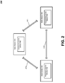
- FIG. 2 illustrates an exemplary exchange of information among radio modules.
- FIGS. 3A and 3B are diagrams illustrating the coordination of transmissions among radio modules.
- FIG. 4 illustrates an embodiment of an apparatus.
- FIG. 5 illustrates an exemplary exchange of information between radio modules and a coordination module.
- FIG. 6 is a diagram illustrating the scheduling of transmissions
- FIGS. 7 and 8 are exemplary flow diagrams
- FIG. 9 illustrates an embodiment of a system.
- an apparatus may include first and second transceivers, a first control module, and a second control module.
- Each transceiver may send one or more wireless transmissions, which are scheduled by the control modules.
- the first control module may schedule transmissions of the first transceiver and the second control module may schedule transmissions of the second transceiver. These may be scheduled to avoid the transmissions of the first transceiver overlapping in time with the transmissions of the second transceiver.
- an apparatus may include first and second transceivers, and a coordination module.
- Each of the transceivers may send one or more wireless transmissions. These transmissions are scheduled by the coordination module to avoid the wireless transmissions of the first transceiver overlapping with the wireless transmissions of the second transceiver.
- Various advantages may be obtained through the avoidance of overlapping transmissions. For example, the occurrence of excessive power drains on an apparatus's power supply may be reduced. In addition, the degradation of wireless transmissions by spurious emissions may be reduced. Moreover, intended recipients of such transmissions may experience less interference.
- Embodiments of the present invention may involve a variety of wireless communications technologies. These technologies may include cellular and data networking systems. Exemplary data networking systems include wireless local area networks (WLANs), wireless metropolitan area networks (WMANs), and personal area networks (PANs).
- WLANs wireless local area networks
- WMANs wireless metropolitan area networks
- PANs personal area networks
- Various embodiments may comprise one or more elements.
- An element may comprise any structure arranged to perform certain operations.
- Each element may be implemented as hardware, software, or any combination thereof, as desired for a given set of design parameters or performance constraints.
- an embodiment may be described with a limited number of elements in a certain topology by way of example, the embodiment may include other combinations of elements in alternate arrangements as desired for a given implementation.
- any reference to “one embodiment” or “an embodiment” means that a particular feature, structure, or characteristic described in connection with the embodiment is included in at least one embodiment.
- the appearances of the phrase “in one embodiment” in various places in the specification are not necessarily all referring to the same embodiment.
- FIG. 1 illustrates one embodiment of an apparatus that may communicate across wireless links.
- FIG. 1 shows an apparatus 100 comprising various elements. The embodiments, however, are not limited to these depicted elements.
- FIG. 1 shows that apparatus 100 may include multiple radio modules 102 a - n , a host 106 , and an interconnection medium 108 . These elements may be implemented in hardware, software, firmware, or in any combination thereof. Moreover, these elements may receive operational power from a power supply, such as a rechargeable battery (not shown).
- a power supply such as a rechargeable battery (not shown).
- Each radio module 102 may communicate, through a corresponding antenna 112 , with remote devices across various types of wireless links.
- radio modules 102 may communicate across data networking links.
- data networking links include wireless local area network (WLAN) links, such as IEEE 802.11 WiFi links.
- WLAN wireless local area network
- WMAN wireless metropolitan area
- WiBro WiBro links.
- WB WiMedia/Ultra Wide Band
- exemplary data networking links include personal area networks (PAN) links such as Bluetooth links, and WiBree (initially developed by Nokia Research Centre) links. The embodiments, however, are not limited to these examples.
- radio modules 102 may communicate across wireless links provided by one or more cellular systems.
- Exemplary cellular systems include Code Division Multiple Access (CDMA) systems, Global System for Mobile Communications (GSM) systems, North American Digital Cellular (NADC) systems, Time Division Multiple Access (TDMA) systems, Extended-TDMA (E-TDMA) systems, Digital Advanced Mobile Phone Service (IS-136/TDMA) systems, Narrowband Advanced Mobile Phone Service (NAMPS) systems, third generation (3G) systems such as Wide-band CDMA (WCDMA), CDMA-2000, Universal Mobile Telephone System (UMTS), cellular radiotelephone systems compliant with the Third-Generation Partnership Project (3GPP), and so forth.
- CDMA Code Division Multiple Access
- GSM Global System for Mobile Communications
- NADC North American Digital Cellular
- TDMA Time Division Multiple Access
- E-TDMA Extended-TDMA
- IS-136/TDMA Extended-TDMA
- NAMPS Narrowband Advanced Mobile Phone Service
- third generation (3G) systems such as Wide-band CDMA (WCDMA),
- FIG. 1 shows that each radio module 102 includes a transceiver 114 and a transmission control module 116 . More particularly, FIG. 1 shows radio module 102 a having a transceiver 114 a and a transmission control module 116 a , radio module 102 a having a transceiver 114 a and a transmission control module 116 a , and radio module 102 n having a transceiver 114 n and a transmission control module 116 n.
- Each transceiver 114 may include a transmitter to send wireless transmissions.
- each transceiver 114 may include a receiver to receive wireless transmissions. These transmissions comprise signals that are generated according to various modulation schemes and are transmitted at various frequencies.
- each transceiver 114 may include electronics, such as modulators, demodulators, amplifiers, filters, and so forth.
- FIG. 1 shows that each transmission control module 116 is coupled to a corresponding transceiver 114 .
- transmission control module 116 a is coupled to a transceiver 114 a
- transmission control module 116 b is coupled to a transceiver 114 b
- transmission control module 116 n is coupled to a transceiver 114 n.
- Each transmission control module 116 may direct when its coupled transceiver 114 sends wireless transmissions. This may involve a transmission control module 116 sending a transmission directive to its coupled transceiver 114 . In addition, each transceiver 114 may indicate to its coupled transmission control module 116 when it is ready to send a transmission. Such directives and indications may be in the form of signals, data messages, and so forth.
- Transmission control modules 116 perform scheduling of wireless transmissions for their corresponding transceivers 114 . This scheduling may be performed to avoid transmissions from different radio modules 102 overlapping in time. Such scheduling may involve the exchange of information between radio modules 102 . For instance, transmission control modules 116 of different radio modules 102 may exchange various messages or signals with each other. These messages or signals may pertain to the operation of transceivers 114 .
- Such messages or signals may in the form of requests and responses. For example, when a transceiver 114 of a particular radio module 102 is ready to send a wireless transmission, a request for transmission may be sent to the other radio module(s) 102 .
- the other radio module(s) 102 may evaluate such requests and generate a response. For example, a responding radio module 102 may generate an approval response granting permission for the requesting radio module 102 to transmit. Alternatively, a responding radio module 102 may generate a denial response, which disapproves of the requesting radio module 102 sending its wireless transmission.
- This evaluation of requests and generation of responses may be performed by the transmission control module 116 at each responding radio module 102 .
- These messages may be implemented as signals allocated to one or more signal lines. However, further embodiments may alternatively employ data messages. Such data messages may be sent across various connections. Exemplary connections include parallel interfaces, serial interfaces, and bus interfaces.
- a responding radio module 102 may generate an approval response upon the occurrence of one or more approval conditions.
- One such condition may be that the responding radio module 102 is unprepared to send any wireless transmissions.
- a request may convey various forms of information, such as a priority assigned to the requested transmissions and/or a quality of service associated with the requested transmission. Also, a request may include information regarding the requested transmission's duration and/or its transmission type (e.g., ACKNOWLEDGEMENT, TCP data, MAC data, etc.).
- a request may include information regarding the requested transmission's duration and/or its transmission type (e.g., ACKNOWLEDGEMENT, TCP data, MAC data, etc.).
- a responding radio module 102 may approve a request when the responding radio module 102 is prepared to send a wireless transmission having a lower priority than the priority indicated by the request.
- approval may be granted when the responding radio module 102 is prepared to send a wireless transmission having a priority that is equal to or less than the priority indicated by the request.
- approval may be granted based on quality of service (QOS) information provided with the request. For example, approval may be granted when a request indicates a QOS that is above a predetermined threshold.
- QOS quality of service
- a responding radio module 102 may deny a request when no approval conditions exist. For instance, a responding radio module 102 may respond to a request with a denial when it is prepared to send a wireless transmission having a greater priority than the priority indicated by the request. Alternatively, a denial may occur when the responding radio module 102 is prepared to send a wireless transmission having a priority that is greater to or equal than the priority indicated by the request.
- a requesting transmission control module 116 Upon the receipt of responses from other radio modules 102 , a requesting transmission control module 116 makes a transmission decision. For instance, if all of the received response(s) indicate approval, then the transmission control module 116 directs its coupled transceiver 114 to send its transmission. However, if one or more of the received response(s) indicates denial, then the transmission control module 116 does not direct its coupled transceiver 114 to send its transmission.
- the transmission control module 116 may send a further transmission request to the one or more other radio modules 102 .
- Such a further request may be sent at a subsequent time.
- This subsequent time may be determined according to various techniques. For example, a predetermined delay value may be used. Alternatively, a randomly generated delay time (or backoff delay) may be used. Such random generation may occur each time a transmission control module 116 decides to send a subsequent transmission request.
- FIG. 1 shows that apparatus 100 may further include a host 106 , which may exchange information with radio modules 102 a - n . As shown in FIG. 1 , such exchanges may occur across interconnection medium 108 . For instance, host 106 may send information to these radio modules for wireless transmission. Conversely, radio modules 102 a - n may send information to host 106 that was received in wireless transmissions. In addition, host 106 may exchange information with radio modules 102 a - n regarding their configuration and operation. Examples of such information include control directives issued by host 106 .
- host 106 may perform operations associated with one or more protocols (e.g., multiple protocols at various layers). Additionally, host 106 may perform operations associated with user applications. Exemplary user applications include telephony, text messaging, e-mail, web browsing, word processing, and so forth. Moreover, host 106 may provide one or more functional utilities that are available to various protocols, operations, and/or applications. Exemplary utilities include operating systems, device drivers, user interface functionality, and so forth.
- Interconnection medium 108 provides for couplings among elements, such as radio module 102 and host 106 .
- interconnection medium 108 may include, for example, one or more bus interfaces. Exemplary interfaces include Universal Serial Bus (USB) interfaces, as well as various computer system bus interfaces. Additionally or alternatively, interconnection medium 108 may include one or more point-to-point connections (e.g., parallel interfaces, serial interfaces, etc.) between various element pairings. Such connection may comprise one or more signal lines. In embodiments, interconnection medium 108 may provide for the exchange of information between radio modules 102 (e.g., between transmission control modules 116 ), as described herein.
- apparatus 100 may engage in wireless communications with various types of networks.
- apparatus 100 may coordinate access information among radio modules 102 based on an assessment of its locality.
- FIG. 1 provides an exemplary apparatus arrangement.
- the embodiments are not limited to this arrangement.
- FIG. 1 shows host 106 being coupled to one or more radio modules via interconnection medium 108 .
- the embodiments are not limited as such.
- embodiments may not include a separate host.
- embodiments may provide an integrated host/radio architecture.
- features of a host and one or more radio modules may be implemented together in a single entity, such as a processor or package.
- a single processor or processing entity
- interconnection medium 108 may include non-physical aspects. More particularly, such interconnectivity may be implemented through messages passed between processes or software modules.
- FIG. 2 is a diagram 200 illustrating an exemplary manner in which information regarding the operation of radio modules may be exchanged. This manner of exchange is described with reference to apparatus 100 of FIG. 1 . However, this manner of exchange may also be employed by other embodiments.
- information exchanges 202 may occur between radio modules 102 . More particularly, FIG. 2 shows an exchange 202 a that occurs between radio modules 102 a and 102 b , an exchange 202 b that occurs between radio modules 102 b and 102 n , and an exchange 202 c that occurs between radio modules 102 a and 102 n . As described above, such exchanges may be handled by transmission control modules 116 .
- exchanges may include various forms of information. Examples of such information may include transmission requests, responses to such requests, and indications of occurring transmissions. Examples involving such information are described, for example, with reference to FIGS. 3A and 3B .
- FIGS. 3A and 3B are diagrams illustrating examples involving the scheduling and coordination of transmissions.
- FIG. 3A provides an example in which a radio module receives authorization to initiate a wireless transmission
- FIG. 3B is an example in which a radio module fails to receive such authorization.
- FIG. 3A shows a block 301 , which indicates that radio module 102 a is ready to send a transmission.
- radio module 102 a sends a transmission request 302 a to radio module 102 b and a transmission request 302 b to radio module 102 n .
- these are shown as separate requests, these may be implemented as a single request (e.g., a single signal or message) that is “broadcast” or addressed to both radio modules 102 b and 102 n .
- radio modules 102 b and 102 n evaluate the request(s), as indicated by blocks 304 a and 304 b.
- radio module 102 b sending an approval response 306 a and radio module 102 n sending an approval response 306 b .
- a block 308 initiates sending the transmission of radio module 102 a . As described above, this may involve transmission control module 116 a directing transceiver 114 a to send the transmission.
- FIG. 3B is similar to FIG. 3A .
- FIG. 3B indicates, by block 320 , that radio module 102 a is ready to send a transmission.
- FIG. 3B shows radio module 102 a sending transmission requests 322 a and 322 b , which are evaluated by blocks 324 a and 324 b.
- FIG. 3B only radio module 102 b grants approval. More particularly, FIG. 3B shows that radio module 102 b sends an approval response 326 to radio module 102 a , while radio module 102 n sends a denial response 328 to radio module 102 a . As a result, a block 330 determines that radio module 102 a should refrain from sending its transmission.
- FIG. 3B shows a block 332 , in which radio module 102 a makes a determination to issues a further request to send its transmission.
- block 332 may establish when to send the further request. As described above, this may involve the use of a predetermined delay time or a randomly generated delay time.
- FIG. 4 illustrates a further apparatus embodiment.
- FIG. 4 shows an apparatus 400 , which is similar to apparatus 100 of FIG. 1 .
- apparatus 400 includes a coordination module 402 .
- transmission control modules 116 have been replaced with transmission control modules 404 .
- FIG. 4 shows radio module 102 a having a transmission control module 404 a , radio module 102 b having a transmission control module 404 b , and radio module 102 n having a transmission control module 404 n .
- Coordination module 402 and transmission control modules 404 may be implemented in hardware, software, firmware, or any combination thereof.
- Coordination module 402 schedules transmissions for each of radio modules 102 (e.g., for each of transceivers 114 ). This may be done to avoid such transmissions overlapping in time. Such scheduling may involve coordination module 402 exchanging information with radio modules 102 . For example, coordination module 402 may exchange information with transmission control modules 402 .
- coordination module 402 may include a schedule data storage medium 406 to store and maintain a “master schedule” of the transmissions it schedules. Thus, coordination module 402 may use storage medium 402 to find available transmission times for requested transmissions.
- Storage medium 406 may be implemented in memory or other suitable information storage media, as described herein.
- FIG. 4 shows that each transmission control module 404 is coupled to a corresponding transceiver 114 .
- transmission control module 404 a is coupled to transceiver 114 a
- transmission control module 404 b is coupled to transceiver 114 b
- transmission control module 404 n is coupled to transceiver 114 n.
- Each transmission control module 404 may direct when its coupled transceiver 114 sends transmissions. This may involve a transmission control module 404 sending a transmission directive to its coupled transceiver 114 . In addition, each transceiver 114 may indicate to its coupled transmission control module 404 when it is ready to send a transmission. Such directives and indications may be in the form of signals, data messages, and so forth.
- radio modules 102 may exchange information with coordination module 402 .
- FIG. 5 is a diagram 500 illustrating an exemplary manner in which such information exchange may occur.
- information exchanges 502 may occur between radio modules 102 and coordination module 402 according to a “hub and spoke” topology. More particularly, FIG. 5 shows an exchange 502 a that occurs between radio module 102 a and coordination module 402 , an exchange 502 b that occurs between radio module 102 b and coordination module 402 , and an exchange 502 c that occurs between radio module 102 n and coordination module 402 .
- such exchanges may be handled by its transmission control module 404 .
- FIG. 6 illustrates an example of such requests and responses.
- FIG. 6 is a diagram illustrating the scheduling of transmission for radio modules 102 a , 102 b , and 102 n . This example is described with reference to apparatus 400 of FIG. 4 . However, the embodiments are not limited to this context.
- FIG. 6 shows blocks 602 , 604 , and 606 , which indicate that radio modules 102 a , 102 b , and 102 n are ready to send transmissions.
- radio modules 102 a , 102 b , and 102 n send transmission requests to coordination module 402 . More particularly, FIG. 6 shows radio module 102 a sending a transmission request 608 , radio module 102 b sending a transmission request 610 , and radio module 102 n sending a transmission request 612 .
- these requests may be sent by transmission control modules 404 a , 404 b , and 404 n .
- these transmission control modules 404 may send such requests upon receipt of a ready to transmit indication from their coupled transceiver 114 .
- Requests 608 , 610 , and 612 may each include various forms of information.
- these requests may include transmission priority indicators and/or quality of service (QOS) information.
- a transmission request may include a duration indicator that indicates the length of the requested transmission.
- a request may include transmission type information (e.g., ACKNOWLEDGEMENT, TCP data, MAC data, etc.). Such information may be evaluated by coordination module in scheduling transmissions and generating scheduling directives for the requesting radio modules 102 .
- coordination module 402 evaluates transmission requests 608 , 610 , and 612 , and determines (schedules) transmission times for each requested transmission. This evaluation and scheduling may be performed to avoid transmissions from different radio modules 102 overlapping in time. In performing such operations, coordination module 402 may access and update information in schedule data storage medium 406 to maintain a transmission schedule and find available transmission times.
- FIG. 6 shows a single block 614 evaluating and scheduling multiple transmission requests
- multiple requests may be evaluated individually or together (e.g., concurrently). In either case, transmission requests may be given precedence in accordance with any information indicated by the requests. Such information may priority or QOS indicators, transmission duration indicators, and so forth.
- coordination module 402 Upon scheduling one or more transmissions, coordination module 402 sends corresponding transmission directives to the requesting radio modules 102 .
- FIG. 6 shows coordination module 402 sending a scheduling directive 616 to radio module 102 n , a scheduling directive 618 to radio module 102 b , and a scheduling directive 620 to radio module 102 a .
- Each of these directives indicates to a radio module 102 when it may send its transmission.
- radio modules 102 a , 102 b , and 102 n may each send transmissions according to the scheduling information provided by these directives.
- FIG. 7 illustrates an exemplary logic flow 700 , which may be representative of the operations executed by one or more embodiments described herein.
- logic flow 700 includes a block 702 , which exchanges information regarding operation of co-located first and second transceivers.
- these co-located radio modules may be within the apparatus of FIG. 1 .
- the embodiments are not limited to this context.
- logic flows may pertain to the exchange of such information involving any number of transceivers.
- a block 704 schedules transmissions of the first transceiver based on the exchanged information. This scheduling is to avoid the transmissions of the first transceiver overlapping with transmissions of the second transceiver.
- a block 706 schedules transmissions of the second transceiver based on the exchanged information. This scheduling also is to avoid the transmissions of the second transceiver overlapping with transmissions of the first transceiver.
- FIG. 8 illustrates an exemplary logic flow 800 , which may be representative of the operations executed by one or more embodiments described herein.
- logic flow 800 includes a block 802 , which receives a request for a first transceiver to send a first wireless transmission.
- a block 804 receives a request for a second transceiver to send a second wireless transmission.
- a block 806 may schedule the requested wireless transmissions to not overlap in time. As described above, such scheduling for such requests may be handled individually or together. Moreover, such scheduling may give precedence to indicated priorities or QOS information.
- a block 808 directs the first transceiver to send its transmission at its scheduled time.
- a block 810 directs the second transceiver to send its transmission at its scheduled time.
- blocks 802 , 804 , 806 , 808 , and 810 may be implemented by coordination module 402 . However, the embodiments are not limited to such.
- embodiments may provide advantages involving reduced power demands, lower spurious emissions, and interference mitigation. Such advantages are now described in greater detail.
- radio modules may share a common power source (typically a battery).
- a transceiver transmits wireless signals
- its amplifier consumes a large amount of power from this power source.
- the amplifier draws a large amount of electrical current from the power source during transmission.
- multiple radios happen turn on their transmit amplifiers at the same time, they may temporarily draw so much current that they exceed the capacity of the power source to deliver the required current.
- the voltage output of the power source may drop below minimum requirements, or the supply current of the power source may become too low to guarantee operation of the corresponding radio module.
- problems may occur, such as excessive phase error, the introduction of spectral spurs, and radio module performance reduction.
- the occurrence of such problems may be reduced.
- insufficient isolation may exist between multiple radio modules.
- an individual transceiver amplifier may “see” a lot of unexpected power delivered to its front end.
- Such unexpected signals may interfere with the amplifier's operation and cause undesired spurious emissions.
- spurious transmissions can degrade signal quality (often measured by Error Vector Magnitude) to an unacceptable level. Avoiding simultaneous transmissions may reduce such problems.
- simultaneous transmissions may present intended recipients of such transmissions with multiple interfering signals (e.g., interfering Bluetooth and WiFi signals).
- interfering signals e.g., interfering Bluetooth and WiFi signals.
- the interfering signals may be too powerful for adequate reception of desired signal(s).
- avoiding overlapping transmissions may reduce the occurrence of such interference.
- FIG. 9 illustrates an embodiment of a system 900 .
- This system may be suitable for use with one or more embodiments described herein, such as apparatus 100 , apparatus 400 , logic flows 700 and 800 , and so forth. Accordingly, system 900 may engage in wireless communications across various link types, such as the ones described herein. In addition, system 900 may perform various user applications.
- system 900 may include a device 902 , multiple communications networks 904 , and one or more remote devices 906 .
- FIG. 9 shows that device 902 may include the elements of FIG. 1 .
- device 902 may alternatively include the elements of FIG. 4 , as well as elements of other embodiments. As described above, such other embodiments may involve integrated host/radio architectures.
- device 902 may include a memory 908 , a user interface 910 , a wired communications interface 912 , a power supply (e.g., a battery) 914 , and an expansion interface 916 . These elements may be implemented in hardware, software, firmware, or any combination thereof.
- Power supply 914 provides operational power to elements of device 902 .
- power supply 914 may include a battery.
- a battery may be rechargeable and/or removable.
- power supply 914 may include an interface to an external power source, such as an alternating current (AC) source.
- AC alternating current
- Memory 908 may store information in the form of data.
- memory 908 may contain application documents, e-mails, sound files, and/or images in either encoded or unencoded formats.
- memory 908 may store control logic, instructions, and/or software components. These software components include instructions that can be executed by one or more processors. Such instructions may provide functionality of one or more elements. Exemplary elements include host 106 , one or more components within radio modules 102 a - n , coordination module 402 (e.g., of apparatus 400 ), user interface 910 , and/or communications interface 912 .
- Memory 908 may be implemented using any machine-readable or computer-readable media capable of storing data, including both volatile and non-volatile memory.
- memory 908 may include read-only memory (ROM), random-access memory (RAM), dynamic RAM (DRAM), Double-Data-Rate DRAM (DDRAM), synchronous DRAM (SDRAM), static RAM (SRAM), programmable ROM (PROM), erasable programmable ROM (EPROM), electrically erasable programmable ROM (EEPROM), flash memory, polymer memory such as ferroelectric polymer memory, ovonic memory, phase change or ferroelectric memory, silicon-oxide-nitride-oxide-silicon (SONOS) memory, magnetic or optical cards, or any other type of media suitable for storing information.
- ROM read-only memory
- RAM random-access memory
- DRAM dynamic RAM
- DDRAM Double-Data-Rate DRAM
- SDRAM synchronous DRAM
- SRAM static RAM
- PROM programmable ROM
- EPROM eras
- memory 908 may be included in other elements of system 900 .
- some or all of memory 908 may be included on a same integrated circuit or chip with elements of apparatus 100 and/or apparatus 400 .
- some portion or all of memory 908 may be disposed on an integrated circuit or other medium, for example a hard disk drive, which is external.
- the embodiments are not limited in this context.
- User interface 910 facilitates user interaction with device 902 . This interaction may involve the input of information from a user and/or the output of information to a user. Accordingly, user interface 910 may include one or more devices, such as a keyboard (e.g., a full QWERTY keyboard), a keypad, a touch screen, a microphone, and/or an audio speaker.
- a keyboard e.g., a full QWERTY keyboard
- keypad e.g., a touch screen
- microphone e.g., a microphone
- an audio speaker e.g., a microphone
- Wired communications interface 912 provides for the exchange of information with a device 906 c (e.g., a proximate device), such as a personal computer. This exchange of information may be across one or more wired connections. Examples of such connections include USB interfaces, parallel interfaces, and/or serial interfaces. In addition, interface 912 may provide for such exchanges across wireless connections(s). An infrared interface is an example of such a connection.
- the information exchanged with such proximate devices may include e-mail, calendar entries, contact information, as well as other information associated with personal information management applications. In addition, such information may include various application files, and content (e.g., audio, image, and/or video).
- Wired communications interface 912 may include various components, such as a transceiver and control logic to perform operations according to one or more communications protocols.
- communications interface 912 may include input/output (I/O) adapters, physical connectors to connect the I/O adapter with a corresponding communications medium.
- I/O input/output
- FIG. 9 shows that device 902 may communicate across wireless networks 904 a and 904 b .
- FIG. 9 shows communications across network 904 a being handled by radio module 102 a
- communications across network 904 b being handled by radio module 102 n .
- First wireless network 904 a may be a cellular network
- second wireless network 904 b may be a wireless data network.
- radio module 102 b may also communicate across a wireless network.
- FIG. 9 shows device 902 engaging in wireless communications (e.g., telephony or messaging) with a mobile device 906 a .
- wireless communications e.g., telephony or messaging
- FIG. 9 shows device engaging in wireless communications (e.g., WLAN, WMAN, and/or PAN communications) with an access point 906 b .
- access point 906 b may provide device 902 with access to further communications resources.
- FIG. 9 shows access point 906 b providing access to a packet network 904 c , such as the Internet.
- Expansion interface 916 may be in the form of an expansion slot, such as a secure digital (SD) slot. Accordingly, expansion interface 916 may accept memory, external radios (e.g., global positioning system (GPS), Bluetooth, WiFi radios, etc.), content, hard drives, and so forth. The embodiments, however, are not limited to SD slots. Other expansion interface or slot technology may include memory stick, compact flash (CF), as well as others.
- SD secure digital
- Various embodiments may be implemented using hardware elements, software elements, or a combination of both.
- hardware elements may include processors, microprocessors, circuits, circuit elements (e.g., transistors, resistors, capacitors, inductors, and so forth), integrated circuits, application specific integrated circuits (ASIC), programmable logic devices (PLD), digital signal processors (DSP), field programmable gate array (FPGA), logic gates, registers, semiconductor device, chips, microchips, chip sets, and so forth.
- Examples of software may include software components, programs, applications, computer programs, application programs, system programs, machine programs, operating system software, middleware, firmware, software modules, routines, subroutines, functions, methods, procedures, software interfaces, application program interfaces (API), instruction sets, computing code, computer code, code segments, computer code segments, words, values, symbols, or any combination thereof. Determining whether an embodiment is implemented using hardware elements and/or software elements may vary in accordance with any number of factors, such as desired computational rate, power levels, heat tolerances, processing cycle budget, input data rates, output data rates, memory resources, data bus speeds and other design or performance constraints.
- Coupled and “connected” along with their derivatives. These terms are not intended as synonyms for each other. For example, some embodiments may be described using the terms “connected” and/or “coupled” to indicate that two or more elements are in direct physical or electrical contact with each other. The term “coupled,” however, may also mean that two or more elements are not in direct contact with each other, but yet still co-operate or interact with each other.
- Some embodiments may be implemented, for example, using a machine-readable medium or article which may store an instruction or a set of instructions that, if executed by a machine, may cause the machine to perform a method and/or operations in accordance with the embodiments.
- a machine may include, for example, any suitable processing platform, computing platform, computing device, processing device, computing system, processing system, computer, processor, or the like, and may be implemented using any suitable combination of hardware and/or software.
- the machine-readable medium or article may include, for example, any suitable type of memory unit, memory device, memory article, memory medium, storage device, storage article, storage medium and/or storage unit, for example, memory, removable or non-removable media, erasable or non-erasable media, writeable or re-writeable media, digital or analog media, hard disk, floppy disk, Compact Disk Read Only Memory (CD-ROM), Compact Disk Recordable (CD-R), Compact Disk Rewriteable (CD-RW), optical disk, magnetic media, magneto-optical media, removable memory cards or disks, various types of Digital Versatile Disk (DVD), a tape, a cassette, or the like.
- memory removable or non-removable media, erasable or non-erasable media, writeable or re-writeable media, digital or analog media, hard disk, floppy disk, Compact Disk Read Only Memory (CD-ROM), Compact Disk Recordable (CD-R), Compact Disk Rewriteable (CD-RW), optical disk, magnetic
- the instructions may include any suitable type of code, such as source code, compiled code, interpreted code, executable code, static code, dynamic code, encrypted code, and the like, implemented using any suitable high-level, low-level, object-oriented, visual, compiled and/or interpreted programming language.
- processing refers to the action and/or processes of a computer or computing system, or similar electronic computing device, that manipulates and/or transforms data represented as physical quantities (e.g., electronic) within the computing system's registers and/or memories into other data similarly represented as physical quantities within the computing system's memories, registers or other such information storage, transmission or display devices.
- physical quantities e.g., electronic
Abstract
Description
Claims (20)
Priority Applications (1)
| Application Number | Priority Date | Filing Date | Title |
|---|---|---|---|
| US11/617,277 US7920883B2 (en) | 2006-12-28 | 2006-12-28 | Coordination of transmissions in wireless communications devices |
Applications Claiming Priority (1)
| Application Number | Priority Date | Filing Date | Title |
|---|---|---|---|
| US11/617,277 US7920883B2 (en) | 2006-12-28 | 2006-12-28 | Coordination of transmissions in wireless communications devices |
Publications (2)
| Publication Number | Publication Date |
|---|---|
| US20080161031A1 US20080161031A1 (en) | 2008-07-03 |
| US7920883B2 true US7920883B2 (en) | 2011-04-05 |
Family
ID=39584755
Family Applications (1)
| Application Number | Title | Priority Date | Filing Date |
|---|---|---|---|
| US11/617,277 Active 2029-07-09 US7920883B2 (en) | 2006-12-28 | 2006-12-28 | Coordination of transmissions in wireless communications devices |
Country Status (1)
| Country | Link |
|---|---|
| US (1) | US7920883B2 (en) |
Cited By (5)
| Publication number | Priority date | Publication date | Assignee | Title |
|---|---|---|---|---|
| US20100227570A1 (en) * | 2009-03-09 | 2010-09-09 | Palm, Inc. | Isolation techniques for multiple co-located radio modules |
| US20110065394A1 (en) * | 2009-09-11 | 2011-03-17 | Carlos Cordeiro | Traffic constraints in a mmWAVE wireless network |
| US20120215778A1 (en) * | 2011-02-21 | 2012-08-23 | Samsung Electronics Co., Ltd. | Apparatus and method for managing content data in portable terminal |
| US8755747B2 (en) | 2006-10-31 | 2014-06-17 | Qualcomm Incorporated | Techniques to control transmit power for a shared antenna architecture |
| US9693390B2 (en) | 2009-06-01 | 2017-06-27 | Qualcomm Incorporated | Techniques to manage a mobile device based on network density |
Families Citing this family (28)
| Publication number | Priority date | Publication date | Assignee | Title |
|---|---|---|---|---|
| US8369782B1 (en) | 2007-08-13 | 2013-02-05 | Marvell International Ltd. | Bluetooth wideband scan mode |
| US8577305B1 (en) | 2007-09-21 | 2013-11-05 | Marvell International Ltd. | Circuits and methods for generating oscillating signals |
| US8315234B2 (en) * | 2007-09-24 | 2012-11-20 | Wi-Lan, Inc. | Time multiplexing for coexistence within multiple communication systems |
| US8588705B1 (en) | 2007-12-11 | 2013-11-19 | Marvell International Ltd. | System and method of determining Power over Ethernet impairment |
| JP5343276B2 (en) | 2008-06-16 | 2013-11-13 | マーベル ワールド トレード リミテッド | Near field communication |
| US8310967B1 (en) | 2008-06-19 | 2012-11-13 | Marvell International Ltd. | Infrastructure and ad-hoc node device |
| US8600324B1 (en) | 2008-06-27 | 2013-12-03 | Marvell International Ltd | Circuit and method for adjusting a digitally controlled oscillator |
| CN103379509A (en) * | 2008-07-02 | 2013-10-30 | 贝莱尔网络公司 | High performance mobility network with autoconfiguration |
| US8472968B1 (en) | 2008-08-11 | 2013-06-25 | Marvell International Ltd. | Location-based detection of interference in cellular communications systems |
| US9288764B1 (en) | 2008-12-31 | 2016-03-15 | Marvell International Ltd. | Discovery-phase power conservation |
| US8619563B2 (en) * | 2009-02-03 | 2013-12-31 | Qualcomm Incorporated | Method and apparatus for interference management in a wireless communication system |
| US11223459B2 (en) * | 2009-02-10 | 2022-01-11 | Telefonaktiebolaget Lm Ericsson (Publ) | Mapping user data onto a time-frequency resource grid in a coordinated multi-point wireless communication system |
| US8472427B1 (en) | 2009-04-06 | 2013-06-25 | Marvell International Ltd. | Packet exchange arbitration for coexisting radios |
| CN101969688B (en) * | 2009-07-28 | 2014-04-16 | 华为技术有限公司 | Carrier processing method, communication device and communication system |
| US9066369B1 (en) | 2009-09-16 | 2015-06-23 | Marvell International Ltd. | Coexisting radio communication |
| US8340034B1 (en) | 2009-11-11 | 2012-12-25 | Marvell International Ltd. | Bluetooth and wireless LAN arbitration |
| US8767771B1 (en) | 2010-05-11 | 2014-07-01 | Marvell International Ltd. | Wakeup beacons for mesh networks |
| US8489022B1 (en) | 2010-08-19 | 2013-07-16 | Qualcomm Incorporated | Arbitration between multiple wireless protocols in a wireless device based on predicted activites |
| EP2630827B1 (en) | 2010-10-20 | 2018-11-21 | Marvell World Trade Ltd. | Pre-association service discovery |
| US8750278B1 (en) | 2011-05-26 | 2014-06-10 | Marvell International Ltd. | Method and apparatus for off-channel device invitation |
| US8983557B1 (en) | 2011-06-30 | 2015-03-17 | Marvell International Ltd. | Reducing power consumption of a multi-antenna transceiver |
| US9125216B1 (en) | 2011-09-28 | 2015-09-01 | Marvell International Ltd. | Method and apparatus for avoiding interference among multiple radios |
| US9036517B2 (en) | 2012-01-09 | 2015-05-19 | Marvell World Trade Ltd. | Methods and apparatus for establishing a tunneled direct link setup (TDLS) session between devices in a wireless network |
| WO2013119810A1 (en) | 2012-02-07 | 2013-08-15 | Marvell World Trade Ltd. | Method and apparatus for multi-network communication |
| US9609676B1 (en) | 2012-03-30 | 2017-03-28 | Marvell International Ltd. | Efficient transition from discovery to link establishment |
| US9450649B2 (en) | 2012-07-02 | 2016-09-20 | Marvell World Trade Ltd. | Shaping near-field transmission signals |
| TWI540927B (en) * | 2014-09-26 | 2016-07-01 | 緯創資通股份有限公司 | Connection method and electronic device |
| US20230029978A1 (en) * | 2021-07-28 | 2023-02-02 | Texas Instruments Incorporated | Channel aware application data transmission for ble devices |
Citations (15)
| Publication number | Priority date | Publication date | Assignee | Title |
|---|---|---|---|---|
| US20010010689A1 (en) * | 2000-01-20 | 2001-08-02 | Awater Geert Arnout | Interoperability for bluetooth/IEEE 802.11 |
| US20020136233A1 (en) * | 2001-03-22 | 2002-09-26 | Minghua Chen | Coordination architecture for wireless communication devices using multiple protocols |
| US20030123405A1 (en) * | 2001-12-27 | 2003-07-03 | Koninklijke Philips Electronics N.V. | Overlapping network allocation vector (ONAV) for avoiding collision in the IEEE 802.11 WLAN operating under HCF |
| US6778491B1 (en) * | 2000-03-31 | 2004-08-17 | Alcatel | Method and system for providing redundancy for signaling link modules in a telecommunication system |
| US20040224708A1 (en) * | 2003-05-09 | 2004-11-11 | Brabenac Charles L. | Reducing interference from closely proximate wireless units |
| US20040253963A1 (en) * | 2003-02-06 | 2004-12-16 | Samsung Electronics Co., Ltd. | Context-based mobile telecommunication method and context-based mobile telecommunication system |
| US20050068965A1 (en) * | 2003-08-26 | 2005-03-31 | Tzu-Ming Lin | Apparatus for controlling multi-mode radio access and method for the same |
| US20050094642A1 (en) * | 2003-10-31 | 2005-05-05 | Rogers Steven A. | Endpoint packet scheduling system |
| US20050170776A1 (en) | 2002-06-07 | 2005-08-04 | David Siorpaes | Wireless technology co-existence |
| US20060053146A1 (en) * | 2004-09-09 | 2006-03-09 | Allhusen Eric J | Data transmission management |
| US20070071026A1 (en) * | 2005-09-23 | 2007-03-29 | Rivulet Communications, Inc. | Compressed video packet scheduling system |
| US7215659B1 (en) * | 2001-10-18 | 2007-05-08 | Oxford Semiconductor, Inc. | Remotely-cooperative scheduling solution for moderating wireless protocols |
| US20070149137A1 (en) * | 2005-12-22 | 2007-06-28 | Tom Richardson | Methods and apparatus for communicating control information |
| US20070238483A1 (en) * | 2006-04-05 | 2007-10-11 | Olivier Boireau | Antenna sharing techniques |
| US20080102885A1 (en) * | 2006-10-31 | 2008-05-01 | Jerome Tu | Coordination Among Multiple Co-Located Radio Modules |
-
2006
- 2006-12-28 US US11/617,277 patent/US7920883B2/en active Active
Patent Citations (17)
| Publication number | Priority date | Publication date | Assignee | Title |
|---|---|---|---|---|
| US20010010689A1 (en) * | 2000-01-20 | 2001-08-02 | Awater Geert Arnout | Interoperability for bluetooth/IEEE 802.11 |
| US6778491B1 (en) * | 2000-03-31 | 2004-08-17 | Alcatel | Method and system for providing redundancy for signaling link modules in a telecommunication system |
| US20020136233A1 (en) * | 2001-03-22 | 2002-09-26 | Minghua Chen | Coordination architecture for wireless communication devices using multiple protocols |
| US7233602B2 (en) * | 2001-03-22 | 2007-06-19 | Oxford Semiconductor, Inc. | Coordination architecture for wireless communication devices using multiple protocols |
| US7215659B1 (en) * | 2001-10-18 | 2007-05-08 | Oxford Semiconductor, Inc. | Remotely-cooperative scheduling solution for moderating wireless protocols |
| US20030123405A1 (en) * | 2001-12-27 | 2003-07-03 | Koninklijke Philips Electronics N.V. | Overlapping network allocation vector (ONAV) for avoiding collision in the IEEE 802.11 WLAN operating under HCF |
| US7164671B2 (en) * | 2001-12-27 | 2007-01-16 | Koninklijke Philips Electronics N.V. | Overlapping network allocation vector (ONAV) for avoiding collision in the IEEE 802.11 WLAN operating under HCF |
| US20050170776A1 (en) | 2002-06-07 | 2005-08-04 | David Siorpaes | Wireless technology co-existence |
| US20040253963A1 (en) * | 2003-02-06 | 2004-12-16 | Samsung Electronics Co., Ltd. | Context-based mobile telecommunication method and context-based mobile telecommunication system |
| US20040224708A1 (en) * | 2003-05-09 | 2004-11-11 | Brabenac Charles L. | Reducing interference from closely proximate wireless units |
| US20050068965A1 (en) * | 2003-08-26 | 2005-03-31 | Tzu-Ming Lin | Apparatus for controlling multi-mode radio access and method for the same |
| US20050094642A1 (en) * | 2003-10-31 | 2005-05-05 | Rogers Steven A. | Endpoint packet scheduling system |
| US20060053146A1 (en) * | 2004-09-09 | 2006-03-09 | Allhusen Eric J | Data transmission management |
| US20070071026A1 (en) * | 2005-09-23 | 2007-03-29 | Rivulet Communications, Inc. | Compressed video packet scheduling system |
| US20070149137A1 (en) * | 2005-12-22 | 2007-06-28 | Tom Richardson | Methods and apparatus for communicating control information |
| US20070238483A1 (en) * | 2006-04-05 | 2007-10-11 | Olivier Boireau | Antenna sharing techniques |
| US20080102885A1 (en) * | 2006-10-31 | 2008-05-01 | Jerome Tu | Coordination Among Multiple Co-Located Radio Modules |
Non-Patent Citations (2)
| Title |
|---|
| 802.15.2 (TM), "Part 15.2: Coexistence of Wireless Personal Area Networks with Other Wireless Devices Operating in Unlicensed Frequency Bands", IEEE Computer Society, New York, NY, Aug. 28, 2003. |
| U.S. Appl. No. 11/555,255, filed Oct. 31, 2006, Jerome C. Tu, et al. |
Cited By (7)
| Publication number | Priority date | Publication date | Assignee | Title |
|---|---|---|---|---|
| US8755747B2 (en) | 2006-10-31 | 2014-06-17 | Qualcomm Incorporated | Techniques to control transmit power for a shared antenna architecture |
| US20100227570A1 (en) * | 2009-03-09 | 2010-09-09 | Palm, Inc. | Isolation techniques for multiple co-located radio modules |
| US8909165B2 (en) | 2009-03-09 | 2014-12-09 | Qualcomm Incorporated | Isolation techniques for multiple co-located radio modules |
| US9693390B2 (en) | 2009-06-01 | 2017-06-27 | Qualcomm Incorporated | Techniques to manage a mobile device based on network density |
| US20110065394A1 (en) * | 2009-09-11 | 2011-03-17 | Carlos Cordeiro | Traffic constraints in a mmWAVE wireless network |
| US8428518B2 (en) * | 2009-09-11 | 2013-04-23 | Intel Corporation | Traffic constraints in a mmWAVE wireless network |
| US20120215778A1 (en) * | 2011-02-21 | 2012-08-23 | Samsung Electronics Co., Ltd. | Apparatus and method for managing content data in portable terminal |
Also Published As
| Publication number | Publication date |
|---|---|
| US20080161031A1 (en) | 2008-07-03 |
Similar Documents
| Publication | Publication Date | Title |
|---|---|---|
| US7920883B2 (en) | Coordination of transmissions in wireless communications devices | |
| US8036683B2 (en) | Coordination among multiple co-located radio modules | |
| US8359022B2 (en) | Coordination of transmissions in wireless communications devices | |
| US8265563B2 (en) | Techniques for enhanced co-existence of co-located radios | |
| EP2606410B1 (en) | Battery power management for a mobile device | |
| US9247473B2 (en) | Motion based handoff control | |
| US8699447B2 (en) | Methods, apparatuses, and computer program products for prioritizing uplink carriers | |
| EP3518589B1 (en) | Power distribution method and device | |
| US8359062B2 (en) | Network access across wireless technologies | |
| EP3406101B1 (en) | Techniques for managing wireless transmission energy budget | |
| US20120329410A1 (en) | Thermal-based flow control | |
| US8050207B2 (en) | Power saving techniques based on coverage conditions | |
| US20230171751A1 (en) | Collision processing method and apparatus | |
| KR20090018786A (en) | Method and apparatus for managing interference in a wireless communication system | |
| EP4221394A1 (en) | Uplink channel transmission method and apparatus, and terminal | |
| US9189988B2 (en) | Management of display parameters in communications devices | |
| CN107509223A (en) | The construction method and device of a kind of virtual subdistrict | |
| CN112261712A (en) | Power regulation method and device | |
| WO2008039899A2 (en) | Acquisition techniques for wireless communications systems | |
| CN114391288A (en) | Mechanism for transmission prioritization | |
| CN112399611B (en) | Access method and device of Internet of things service | |
| WO2024001982A1 (en) | Method and apparatus for determining channel adjustment strategy | |
| WO2024022283A1 (en) | Physical sidelink feedback channel (psfch) sending method and terminal | |
| US20220256580A1 (en) | Resource transmission method and terminal device | |
| WO2014061432A1 (en) | Portable terminal, base station, communication system, frequency determination method, recording medium |
Legal Events
| Date | Code | Title | Description |
|---|---|---|---|
| AS | Assignment |
Owner name: JPMORGAN CHASE BANK, N.A., NEW YORK Free format text: SECURITY AGREEMENT;ASSIGNOR:PALM, INC.;REEL/FRAME:020319/0568 Effective date: 20071024 Owner name: JPMORGAN CHASE BANK, N.A.,NEW YORK Free format text: SECURITY AGREEMENT;ASSIGNOR:PALM, INC.;REEL/FRAME:020319/0568 Effective date: 20071024 |
|
| AS | Assignment |
Owner name: PALM, INC., CALIFORNIA Free format text: ASSIGNMENT OF ASSIGNORS INTEREST;ASSIGNOR:TU, JEROME C.;REEL/FRAME:021279/0057 Effective date: 20070207 |
|
| AS | Assignment |
Owner name: PALM, INC., CALIFORNIA Free format text: RELEASE BY SECURED PARTY;ASSIGNOR:JPMORGAN CHASE BANK, N.A., AS ADMINISTRATIVE AGENT;REEL/FRAME:024630/0474 Effective date: 20100701 |
|
| AS | Assignment |
Owner name: HEWLETT-PACKARD DEVELOPMENT COMPANY, L.P., TEXAS Free format text: ASSIGNMENT OF ASSIGNORS INTEREST;ASSIGNOR:PALM, INC.;REEL/FRAME:025204/0809 Effective date: 20101027 |
|
| STCF | Information on status: patent grant |
Free format text: PATENTED CASE |
|
| AS | Assignment |
Owner name: PALM, INC., CALIFORNIA Free format text: ASSIGNMENT OF ASSIGNORS INTEREST;ASSIGNOR:HEWLETT-PACKARD DEVELOPMENT COMPANY, L.P.;REEL/FRAME:030341/0459 Effective date: 20130430 |
|
| AS | Assignment |
Owner name: PALM, INC., CALIFORNIA Free format text: ASSIGNMENT OF ASSIGNORS INTEREST;ASSIGNOR:HEWLETT-PACKARD DEVELOPMENT COMPANY, L.P.;REEL/FRAME:031837/0544 Effective date: 20131218 Owner name: HEWLETT-PACKARD DEVELOPMENT COMPANY, L.P., TEXAS Free format text: ASSIGNMENT OF ASSIGNORS INTEREST;ASSIGNOR:PALM, INC.;REEL/FRAME:031837/0239 Effective date: 20131218 Owner name: HEWLETT-PACKARD DEVELOPMENT COMPANY, L.P., TEXAS Free format text: ASSIGNMENT OF ASSIGNORS INTEREST;ASSIGNOR:PALM, INC.;REEL/FRAME:031837/0659 Effective date: 20131218 |
|
| AS | Assignment |
Owner name: QUALCOMM INCORPORATED, CALIFORNIA Free format text: ASSIGNMENT OF ASSIGNORS INTEREST;ASSIGNORS:HEWLETT-PACKARD COMPANY;HEWLETT-PACKARD DEVELOPMENT COMPANY, L.P.;PALM, INC.;REEL/FRAME:032126/0541 Effective date: 20140123 |
|
| FPAY | Fee payment |
Year of fee payment: 4 |
|
| MAFP | Maintenance fee payment |
Free format text: PAYMENT OF MAINTENANCE FEE, 8TH YEAR, LARGE ENTITY (ORIGINAL EVENT CODE: M1552); ENTITY STATUS OF PATENT OWNER: LARGE ENTITY Year of fee payment: 8 |
|
| MAFP | Maintenance fee payment |
Free format text: PAYMENT OF MAINTENANCE FEE, 12TH YEAR, LARGE ENTITY (ORIGINAL EVENT CODE: M1553); ENTITY STATUS OF PATENT OWNER: LARGE ENTITY Year of fee payment: 12 |