US7931587B2 - Endoscope with decreased stray light effect that includes a light shielding member that does not pass any light rays emitted from an illuminator - Google Patents
Endoscope with decreased stray light effect that includes a light shielding member that does not pass any light rays emitted from an illuminator Download PDFInfo
- Publication number
- US7931587B2 US7931587B2 US11/474,937 US47493706A US7931587B2 US 7931587 B2 US7931587 B2 US 7931587B2 US 47493706 A US47493706 A US 47493706A US 7931587 B2 US7931587 B2 US 7931587B2
- Authority
- US
- United States
- Prior art keywords
- light
- transparent cover
- illuminator
- optical system
- endoscope
- Prior art date
- Legal status (The legal status is an assumption and is not a legal conclusion. Google has not performed a legal analysis and makes no representation as to the accuracy of the status listed.)
- Expired - Fee Related, expires
Links
Images


Classifications
-
- A—HUMAN NECESSITIES
- A61—MEDICAL OR VETERINARY SCIENCE; HYGIENE
- A61B—DIAGNOSIS; SURGERY; IDENTIFICATION
- A61B1/00—Instruments for performing medical examinations of the interior of cavities or tubes of the body by visual or photographical inspection, e.g. endoscopes; Illuminating arrangements therefor
- A61B1/00064—Constructional details of the endoscope body
- A61B1/00071—Insertion part of the endoscope body
- A61B1/0008—Insertion part of the endoscope body characterised by distal tip features
- A61B1/00096—Optical elements
-
- A—HUMAN NECESSITIES
- A61—MEDICAL OR VETERINARY SCIENCE; HYGIENE
- A61B—DIAGNOSIS; SURGERY; IDENTIFICATION
- A61B1/00—Instruments for performing medical examinations of the interior of cavities or tubes of the body by visual or photographical inspection, e.g. endoscopes; Illuminating arrangements therefor
- A61B1/04—Instruments for performing medical examinations of the interior of cavities or tubes of the body by visual or photographical inspection, e.g. endoscopes; Illuminating arrangements therefor combined with photographic or television appliances
- A61B1/041—Capsule endoscopes for imaging
-
- A—HUMAN NECESSITIES
- A61—MEDICAL OR VETERINARY SCIENCE; HYGIENE
- A61B—DIAGNOSIS; SURGERY; IDENTIFICATION
- A61B1/00—Instruments for performing medical examinations of the interior of cavities or tubes of the body by visual or photographical inspection, e.g. endoscopes; Illuminating arrangements therefor
- A61B1/04—Instruments for performing medical examinations of the interior of cavities or tubes of the body by visual or photographical inspection, e.g. endoscopes; Illuminating arrangements therefor combined with photographic or television appliances
- A61B1/05—Instruments for performing medical examinations of the interior of cavities or tubes of the body by visual or photographical inspection, e.g. endoscopes; Illuminating arrangements therefor combined with photographic or television appliances characterised by the image sensor, e.g. camera, being in the distal end portion
- A61B1/051—Details of CCD assembly
-
- A—HUMAN NECESSITIES
- A61—MEDICAL OR VETERINARY SCIENCE; HYGIENE
- A61B—DIAGNOSIS; SURGERY; IDENTIFICATION
- A61B1/00—Instruments for performing medical examinations of the interior of cavities or tubes of the body by visual or photographical inspection, e.g. endoscopes; Illuminating arrangements therefor
- A61B1/06—Instruments for performing medical examinations of the interior of cavities or tubes of the body by visual or photographical inspection, e.g. endoscopes; Illuminating arrangements therefor with illuminating arrangements
- A61B1/0638—Instruments for performing medical examinations of the interior of cavities or tubes of the body by visual or photographical inspection, e.g. endoscopes; Illuminating arrangements therefor with illuminating arrangements providing two or more wavelengths
-
- A—HUMAN NECESSITIES
- A61—MEDICAL OR VETERINARY SCIENCE; HYGIENE
- A61B—DIAGNOSIS; SURGERY; IDENTIFICATION
- A61B1/00—Instruments for performing medical examinations of the interior of cavities or tubes of the body by visual or photographical inspection, e.g. endoscopes; Illuminating arrangements therefor
- A61B1/06—Instruments for performing medical examinations of the interior of cavities or tubes of the body by visual or photographical inspection, e.g. endoscopes; Illuminating arrangements therefor with illuminating arrangements
- A61B1/0661—Endoscope light sources
-
- H—ELECTRICITY
- H04—ELECTRIC COMMUNICATION TECHNIQUE
- H04N—PICTORIAL COMMUNICATION, e.g. TELEVISION
- H04N23/00—Cameras or camera modules comprising electronic image sensors; Control thereof
- H04N23/50—Constructional details
- H04N23/51—Housings
-
- H—ELECTRICITY
- H04—ELECTRIC COMMUNICATION TECHNIQUE
- H04N—PICTORIAL COMMUNICATION, e.g. TELEVISION
- H04N23/00—Cameras or camera modules comprising electronic image sensors; Control thereof
- H04N23/56—Cameras or camera modules comprising electronic image sensors; Control thereof provided with illuminating means
-
- H—ELECTRICITY
- H04—ELECTRIC COMMUNICATION TECHNIQUE
- H04N—PICTORIAL COMMUNICATION, e.g. TELEVISION
- H04N23/00—Cameras or camera modules comprising electronic image sensors; Control thereof
- H04N23/50—Constructional details
- H04N23/555—Constructional details for picking-up images in sites, inaccessible due to their dimensions or hazardous conditions, e.g. endoscopes or borescopes
Definitions
- the present invention relates to an endoscope for viewing the inside of a body.
- endoscopes In recent years, in areas of medical treatment and in industrial applications, the use of endoscopes has been broadly adopted. In particular, broad use has been made of endoscopes with improved insertability to positions where observations of objects are made, and because the distance from the observed object to the observation unit is set at a fixed distance for ease of observation, the tip of the insertion part of the endoscope is fitted with an illuminator and an imaging device, as well as with a transparent cover that encompasses the illuminator and the imaging device.
- Japanese Laid-Open Patent Application 2001-91860 discloses a capsule endoscope
- WIPO Patent Publication WO 01/65995 discloses an imaging device for a capsule endoscope.
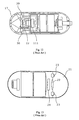
- a cross-sectional view of the capsule endoscope of Japanese Laid-Open Patent Application 2001-91860 is shown in FIG. 12
- a cross-sectional view of the imaging device for a capsule endoscope of Patent Publication WO 01/65995 is shown in FIG. 13 .
- the capsule endoscope thereof includes an objective lens 22 within a hemispheric transparent cover 17 and an image sensor 111 that continuously receives an updated image formed by the objective lens 22 using light provided by light emitting diodes (LEDs) 30 , 30 that surround the objective lens 22 .
- LEDs light emitting diodes
- FIG. 13 shows the capsule endoscope thereof that is constructed with an approximately hemispheric transparent cover 21 , a CMOS image-forming camera 24 that detects an object image formed by the optical system 22 , and illuminators 23 , 23 formed of white light LED light sources, or similar light sources, that illuminate the inside of a body cavity that reflects light through the optical system 22 to form the object image on the CMOS image-forming camera 24 .
- the transparent cover is made from a relatively soft material in order to prevent breakage of the transparent cover.
- the cover material is soft, damage of a minute character, such as scratches, may easily occur on the outer surface of the transparent cover.
- the illumination light emitted from the endoscope illuminator reaches the outer surface of the transparent cover that has been damaged or covered by light-dispersing substances, the illumination light may be scattered or reflected back to the inside of the transparent cover as what is termed herein as “rearward-dispersed” light.
- rearward-dispersed light if transmitted through the image-forming optics within the field of view, including through the entrance pupil of the objective optical system, will result in this light interfering with, and distorting, the desired object image.
- rearward-dispersed light is a major obstacle in obtaining the desired observational information.
- the present invention relates to an endoscope designed so that, if the outer surface of the transparent cover is damaged or covered by substances that result in the illumination light being reflected or scattered back to the inside of the transparent cover, this light will not be incident onto the objective optical system so as to interfere with or distort the desired object image, and thus the desired observational information can be obtained.
- FIG. 1 is a cross-sectional view of the basic construction of the tip of an endoscope of the present invention along the optical axis from the center of the entrance pupil of an objective optical system to the outer surface of a transparent cover;
- FIG. 2 shows the light intensity distribution of reflected light on the outer surface of a transparent cover of an endoscope
- FIG. 3( a ) is a cross-sectional view of a transparent cover in which damage to the outer surface of the transparent cover affects light reflected on the outer surface
- FIG. 3( b ) is a cross-sectional view of a transparent cover in which light dispersing matter adhering to the outer surface of the transparent cover affects illumination light that otherwise transmits through the outer surface;
- FIG. 4 is a cross-sectional view of the basic construction of the tip of an endoscope of the present invention along the optical axis from the center of the entrance pupil of an objective optical system to the outer surface of a transparent cover that has the same construction as that of FIG. 1 ;
- FIG. 5 is a graph of the angular distribution of light intensity emitted by a white light LED
- FIG. 6 is a diagram used to explain the construction of a measuring device for measuring the angular distribution of rearward-dispersed light
- FIG. 7 is a graph of the angular distribution of measured rearward-dispersed light
- FIG. 8 is a cross-sectional view of the tip of the endoscope of Embodiment 1 of the present invention.
- FIG. 9 is a cross-sectional view of the tip of the endoscope of Embodiment 2 of the present invention.
- FIG. 10 is a cross-sectional view of the tip of the endoscope of Embodiment 3 of the present invention.
- FIG. 11 is a cross-sectional view of the tip of the endoscope of Embodiment 4 of the present invention.
- FIG. 12 is a cross-sectional view of a conventional capsule endoscope.
- FIG. 13 is a cross-sectional view of the imaging device for another conventional capsule endoscope.
- an explanation is provided concerning the operational effects of the present invention before considering particular embodiments of the invention.
- the angle ⁇ is the angle a light ray reflected at a point on the external surface of a transparent cover after being emitted as a light ray Q perpendicularly from a light emitting surface of an illuminator makes with a line drawn from the same point on the external surface of the transparent cover to the center of the entrance pupil of the objective optical system.
- FIG. 1 is a cross-sectional view of the basic construction of the tip of an endoscope of the present invention along the optical axis from the center of the entrance pupil 2 of an objective optical system to the outer surface of a transparent cover 1 .
- the endoscope of the present invention shown in FIG. 1 includes an illuminator having a light emitting surface 3 for illuminating the inside of a living body, and an objective optical system (shown by the center of its entrance pupil 2 in FIG. 1 ) for forming an image of a specified object on one side of the objective optical system and illuminated by the illuminator, an imaging device (not shown in FIG. 1 ) for detecting the image, and the transparent cover 1 which encompasses the illuminator and one side of the objective optical system.
- the endoscope of the present invention shown in FIG. 1 is constructed so that the outer surface 1 a and the inner surface 1 b of the transparent cover 1 are each hemispherical surfaces that are rotationally symmetric about the optical axis that passes through the center of the entrance pupil 2 of the objective optical system, and is also constructed so that the spherical center of the external surface 1 a of the transparent cover 1 is coincident with the center of the entrance pupil 2 .
- the light emitting surface 3 is arranged at the periphery of the objective optical system.
- the endoscope of the present invention satisfies the following Condition (1): 10° ⁇ Condition (1)
- FIG. 1 concerns a two-dimensional model related to an endoscope having a single illuminator
- the explanation is easily expanded to calculations with three dimensions being considered.
- the objective can be achieved by calculating only a single angle ⁇ , and a brighter endoscope can be realized.
- the transparent cover 1 is not rotationally symmetric about the optical axis of the objective optical system, or in the case where the position of multiple illuminators are not rotationally symmetric about the optical axis of the objective optical system, concerning all of the illuminators, there is a need to individually obtain the angle ⁇ relative to the light ray Q emitted from the light emitting surface 3 .
- the angle ⁇ is calculated relative to the light ray Q, then concerning the respective illuminators, if adjustment is made of the positional relationship between light emitting surface 3 of the illuminator and the center of the entrance pupil 2 of the objective optical system, the objective can be achieved.
- FIG. 1 considering that there is no damage to, or light-dispersing substances on, the external surface of the transparent cover of the endoscope.
- consideration is given to conditions that sufficiently minimize the amount of rearward-dispersed light, such as caused by damage to the external surface of the transparent cover or by light-dispersing substances on the external surface of the transparent cover of the endoscope and that may enter the entrance pupil of the objective optical system.
- FIG. 2 shows the light intensity distribution of regularly reflected light on the outer surface of a transparent cover of an endoscope.
- the horizontal axis represents the angle in degrees of the reflected light ray R of FIG. 1 from a center “0” angle defined by regular reflection from the outer surface 1 a of the transparent cover 1
- the vertical axis represents the intensity of the light reflected.
- the solid line shows the light intensity distribution of light reflected by the external surface of the transparent cover in the case where there is no damage to, or light-dispersing substances on, the outer surface 1 a of the transparent cover 1
- the broken line shows the light intensity distribution of the rearward-dispersed light in the case where there is damage to the outer surface 1 a of the transparent cover 1 or where there are light-dispersing substances on the outer surface 1 a of the transparent cover 1 .
- FIG. 3( a ) is a cross-sectional view of a transparent cover in which damage to the outer surface of the transparent cover causes light to be reflected at various angles by the outer surface
- FIG. 3( b ) is a cross-sectional view of a transparent cover in which matter adhering to the outer surface of the transparent cover affects light that otherwise would transmit through the outer surface, so that some of the light is directed rearward at various angles.
- illumination light rays 5 emitted from the illuminator are dispersed at various angles rearward as light rays 6 .
- the light rays 6 are reflected at the interface of the outer surface 1 a of the transparent cover 1 with air, due to the large difference in refractive index between the transparent cover and air.
- the effective outer reflecting surface of a conventional transparent cover is similar to a rough surface that causes some of the illumination light that otherwise would transmit through the outer surface to be directed rearward at various angles over a broad range (hence the term ‘rearward-dispersed’ light is used herein).
- the rearward-dispersed light spreads out as shown by the broken line of FIG. 2 as a broad-based light intensity distribution in comparison to the solid line intensity distribution for the case where there is no damage to, or light-dispersing substances on, the outer surface 1 a of the transparent cover 1 .
- the light intensity distributions for regularly reflected light and rearward-dispersed light are shown as overlapping curves near the center “0” angle position, but the particular relative amplitudes shown are merely exemplary and are subject to variation based on the particulars of the damage to, or the light-dispersing substances on, the outer surface 1 a of the transparent cover 1 .
- FIG. 4 is a cross-sectional view of the basic construction of the tip of an endoscope of the present invention along the optical axis from the center of the entrance pupil of an objective optical system to the outer surface of a transparent cover that has the same construction as that of FIG. 1 .
- a light ray B emitted at a selected angle from a point on the light emitting surface 3 of the illuminator is incident on the outer surface 1 a of the transparent cover 1 at a point A where it is reflected as a light ray C, and the angle formed at point A by the reflected light ray C and a line drawn from said point A to the center of the entrance pupil 2 of the objective optical system is ⁇ . If the angle ⁇ is greater than the maximum distribution angle of the rearward-dispersed light, then the amount of rearward-dispersed light reflected from the outer surface 1 a of the transparent cover 1 into the objective optical system will be small.
- the light intensity distribution of the illuminator used in the endoscope is a Gaussian distribution with the peak intensity being at a zero degree angle (0°) as measured from the surface normal, which corresponds to the peak intensity being in a direction that is perpendicular to the light emitting surface.
- FIG. 5 is a graph of the angular distribution of light intensity of a white light LED.
- the white light LED has fluorescent light-dispersing particles positioned forward of a light emitting diode in order to provide white light illumination.
- the horizontal axis is the light distribution angle (in degrees) as measured from the surface normal, and the vertical axis shows the relative intensity of illumination (i.e., normalized to 1.0 at the peak intensity) at the various distribution angles. If the illuminator is formed of a light-dispersing element in front of a light emitting, terminal surface of a light guide, the light intensity distribution is also that shown in FIG. 5 .
- the intensity of light incident normal (i.e., perpendicular) to the outer surface of the transparent cover is normalized to be one, then the intensity of the light dispersed rearward is 0.05, and, to the extent that the angles of light rays incident on the outer surface of the transparent cover depart from this perpendicular incidence (i.e., “0” on the horizontal axis of FIG. 5 ), the intensity will be reduced. Therefore, it is sufficient to consider only light rays with the distribution angle of “0”, since the intensity of illumination light is a maximum at this distribution angle.
- Condition (1) above controls rearward-dispersed light even though the angle ⁇ in FIG. 4 is different from the angle ⁇ explained above with reference to FIG. 1 .
- the angle ⁇ is greater than the maximum angle of the rearward-dispersed light beam (as measured at the 10% intensity profile points of the light beam)
- the intensity of the rearward-dispersed light ray B of FIG. 4 that is incident on the entrance pupil of the objective optical system will be reduced to the point that it is not a problem (as contrasted with the intensity of rearward-dispersed light that would be incident on the entrance pupil of the objective optical system if Condition (1) is not satisfied).
- FIG. 6 is used to explain the construction of a measuring device for measuring the angular distribution of rearward-dispersed light.
- the He—Ne laser oscillator 8 is arranged so that the emitted light beam is incident at an angle of forty-five degrees to the reflecting surface of a prism 9 .
- the distance to the incident point G of the prism 9 from the laser light emission aperture is 600 mm.
- a detector 10 for measuring the rearward-dispersed light is arranged so as to rotate around the center point G. The distance from the point G to the light-receiving surface of the detector 10 is 200 mm.
- the light-receiving surface of the detector is formed in a circular shape having a diameter of 15 mm, and because the area of the light-receiving surface is sufficiently great, the influence of the laser light speckle is averaged, and can largely be ignored.
- FIG. 7 is a graph of the angular distribution of the light at the surface of the prism 9 .
- the horizontal axis shows the angle (as measured from the surface normal) of regular reflected light
- the vertical axis shows the light intensity (in arbitrary units).
- the solid line shows the angular distribution of light in the case when there is no adherence of light-dispersing substances on the surface of the prism 9
- the broken line shows the angular distribution of light when there is adhesion of light-dispersing substances on the surface of the prism 9 .
- the maximum angle of the rearward-dispersed light is not ordinarily fixed, and instead changes somewhat depending upon the type of adhering substance, the state of adhesion, the state of damage, and other factors. Due to this variability in the maximum angle of rearward-dispersed light, it is preferred that the angle ⁇ be fifteen degrees or greater.
- FIG. 8 is a cross-sectional view of the tip of the endoscope of Embodiment 1 of the present invention.
- the endoscope of Embodiment 1 includes a light emitting surface 3 of an illuminator that illuminates the inside of a living body and an objective optical system (not shown in FIG. 8 ) that forms an image of a specified endoscope object position illuminated by the illuminator, an imaging device (not shown in FIG. 8 ) that acquires an image of the specified endoscope object position, and a transparent cover 1 that encompasses the illuminator and the object position side of the objective optical system.
- the endoscope transparent cover 1 has a hemispheric shape with the outer surface of the transparent cover 1 a and the inner surface 1 b both being formed as rotationally symmetric spherical surfaces about an optical axis that passes through the center of the entrance pupil 2 of the objective optical system. Additionally, the endoscope is constructed so that the spherical center of the outer surface 1 a of the transparent cover 1 is coincidental with the center of the entrance pupil 2 of the objective optical system.
- the radius of curvature of the outer surface of the transparent cover 1 is 5.5 mm
- the radius of curvature of the inner surface 1 b is 4.5 mm
- the thickness is 1 mm.
- the refractive index of the material of the transparent cover 1 relative to the e-line (546.07 nm) is 1.527.
- the light emitting surface 3 of the illuminator is arranged at the periphery of the objective optical system in a plane perpendicular to the central axis of the endoscope and passing through the center of the entrance pupil 2 .
- the shortest distance from the central axis of the endoscope to the light emitting surface is 2.8 mm, and the longest distance from the central axis of the endoscope to the light emitting surface is 3.6 mm.
- Table 1 shows the values of the angle ⁇ , as described previously, calculated for light rays emitted from the light emitting surface at various distances from the central axis of the endoscope of Embodiment 1 for light of wavelengths at the e-line.
- FIG. 9 is a cross-sectional view of the tip of the endoscope of Embodiment 2 of the present invention.
- Embodiment 2 is very similar to that of Embodiment 1 described above.
- the transparent cover 1 of the endoscope is formed so that both the inner surface 1 b and the outer surface 1 a of the transparent cover 1 are rotationally symmetric about the central axis of the endoscope and are elliptical surfaces in cross-section.
- the radius of curvature r of the outer surface 1 a of the transparent cover 1 is 6.2443 mm, and the eccentricity K is 0.1.
- the thickness of the transparent cover on the center axis is 1 mm, and the refractive index of the material of the transparent cover at the e-line is 1.527.
- the center of the entrance pupil 2 of the objective optical system is positioned 4.7 mm from the inner surface 1 b of the transparent cover 1 on the central axis of the endoscope.
- the light emitting surface 3 of the illuminator is in a plane that is perpendicular to the central axis of the endoscope and that passes through the center of the entrance pupil 2 .
- the distance to the closest part of the light emitting surface 3 from the central axis of the endoscope is 3.1 mm, and the distance to the farthest part of the light emitting surface 3 from the central axis of the endoscope is 3.9 mm.
- Table 2 shows the values of the angle ⁇ , as described previously, calculated for light rays emitted from the light emitting surface at various distances from the central axis of the endoscope of Embodiment 2 for light of wavelengths at the e-line.
- the positional relationship between the center of the entrance pupil 2 of the objective optical system and the light emitting surface 3 of the illuminator is constructed so as to satisfy Condition (2), and in addition to enabling the minimization of the amount of rearward dispersed light incident on the objective optical system that is caused by dispersed substances adhering to or scratches on the outer surface 1 a of the transparent cover 1 , an endoscope with a small outer diameter can also be realized.
- FIG. 10 is a cross-sectional view of the tip of the endoscope of Embodiment 3 of the present invention.
- the transparent cover 1 of the endoscope is formed as a hemisphere, with the radius of curvature of the outer surface 1 a being 5.5 mm, the radius of curvature of the inner surface 1 b being 4.5 mm, and the thickness of the transparent cover 1 being 1 mm.
- the refractive index at the e-line of the material of the transparent cover 1 is 1.527.
- the center of the entrance pupil 2 of the objective optical system lies on a straight line that is perpendicular to the central axis of the endoscope that passes through the spherical center of the outer surface 1 a of the transparent cover 1 and is at a distance of 2.5 mm from the central axis along the straight line.
- the light emitting surface 3 of the illuminator is in a plane that is perpendicular to the central axis of the endoscope and that passes through the spherical center of the outer surface 1 a of the transparent cover 1 , and is arranged on the periphery of the objective optical system.
- the distance to the light emitting surface 3 from the central axis of the endoscope is measured as positive in the direction facing the center of the entrance pupil 2 , with the closest part being at 0.2 mm and the farthest part being at 1.0 mm.
- Table 3 shows the values of the angle ⁇ , as described previously, calculated for light rays emitted from the light emitting surface at various distances from the central axis of the endoscope of Embodiment 3 for light of wavelengths at the e-line.
- Embodiment 3 because the angle ⁇ is sufficiently greater than the minimum ten degree angle for rearward dispersed light, the amount of light incident on the objective optical system of the rearward dispersed light caused by dispersed substances adhering to or scratches on the outer surface of the transparent cover can be made smaller.
- FIG. 11 is a cross-sectional view of the tip of the endoscope of Embodiment 4 of the present invention.
- Embodiment 4 The construction of Embodiment 4 is very similar to that of Embodiment 1 described above. However, in Embodiment 4, a light shielding member 11 that shields a portion of the light emitting surface 3 is provided. As seen in FIG. 11 , the light shielding member does not pass any light rays that are incident on the light shielding member from the light emitting surface of the illuminator. In addition, the light emitting surface of the illuminator of Embodiment 4 uses measurements which are large in comparison with those of the other embodiments.
- the transparent cover 1 of the endoscope is hemispherical, and the outer surface 1 a and inner surface 1 b of the transparent cover 1 are each formed as surfaces that are rotationally symmetric about the optical axis that passes through the center of the entrance pupil of the objective optical system, with the structure being such that the spherical center of the outer surface 1 a of the transparent cover 1 coincides with the center of the entrance pupil 2 of the objective optical system.
- the radius of curvature of the outer surface 1 a of the transparent cover 1 is 5.5 mm
- the radius of curvature of the inner surface 1 b is 4.5 mm
- the thickness of the transparent cover 1 is 1 mm
- the refractive index at the e-line of the material of the transparent cover is 1.527.
- the light emitting surface 3 of the illuminator is in a plane that is perpendicular to the central axis of the endoscope and that passes through the center of the entrance pupil 2 and is arranged on the periphery of the objective optical system.
- the distance to the closest part of the light emitting surface 3 from the central axis of the endoscope is 1.2 mm, and the distance to the farthest part of the light emitting surface 3 from the central axis of the endoscope is 3.2 mm.
- light shielding member 11 shields a part of the light emitted from the light emitting surface 3 .
- the distance to the closest part of the light shielding member 11 from the central axis of the endoscope is 1.2 mm, and the distance to the farthest part of the light shielding member 11 from the central axis of the endoscope is 2.2 mm.
- Table 4 shows the values of the angle ⁇ , as described previously, calculated for light rays emitted from the light emitting surface at various distances from the central axis of the endoscope of Embodiment 4 for light of wavelengths at the e-line.
- the light shielding member 11 is arranged on the part of the light emitting surface 3 where the value of the angle ⁇ for the light emitted from the light emitting surface 3 of the illuminator would be relatively small so that the angle ⁇ for the illumination light beam is sufficiently greater than the ten degrees minimum angle of the rearward dispersed light. Therefore, the amount of light incident onto the objective optical system of the rearward dispersed light caused by dispersed substances adhering to or scratches on the outer surface of the transparent cover can be made smaller.
Abstract
Description
10°≦α Condition (1)
where
-
- α is the angle formed by a light ray R having a wavelength 546.07 nm that has been specularly reflected at a point P on the
outer surface 1 a of thetransparent cover 1 after being emitted perpendicularly as light ray Q from thelight emitting surface 3 of the illuminator with a line drawn from said point on the external surface of the transparent cover to the center of the entrance pupil of the objective optical system.
- α is the angle formed by a light ray R having a wavelength 546.07 nm that has been specularly reflected at a point P on the
| TABLE 1 | |||
| Distance (mm) From Central | Angle α (°) | ||
| Axis to the Light Emitting | For Light Rays | ||
| Diode Surface | at the e-line | ||
| 2.8 | 19.5 | ||
| 2.9 | 20.2 | ||
| 3.0 | 20.9 | ||
| 3.1 | 21.7 | ||
| 3.2 | 22.4 | ||
| 3.3 | 23.1 | ||
| 3.4 | 23.9 | ||
| 3.5 | 24.6 | ||
| 3.6 | 25.4 | ||
Z=(Y 2 /r)/[1+{1−(K+1)(Y/r)2}1/2] Equation (1)
where
-
- Z is the length (in mm) of a line drawn from a point on the aspheric surface at distance y from the optical axis to the tangential plane of the aspheric surface vertex,
- r is the radius of curvature of the aspheric surface on the optical axis,
- Y is the distance (in mm) from the optical axis, and
- K is the eccentricity.
| TABLE 2 | |||
| Distance (mm) From Central | Angle α (°) | ||
| Axis to the Light Emitting | For Light Rays | ||
| Diode Surface | at the e-line | ||
| 3.1 | 20.0 | ||
| 3.2 | 20.7 | ||
| 3.3 | 21.4 | ||
| 3.4 | 22.1 | ||
| 3.5 | 22.8 | ||
| 3.6 | 23.6 | ||
| 3.7 | 24.3 | ||
| 3.8 | 25.0 | ||
| 3.9 | 25.8 | ||
15°≦α≦30° Condition (2)
where
-
- α is the angle as defined above.
| TABLE 3 | |||
| Distance (mm) From Central | Angle α (°) | ||
| Axis to the Light Emitting | For Light Rays | ||
| Diode Surface | at the e-line | ||
| 0.2 | 17.1 | ||
| 0.3 | 17.9 | ||
| 0.4 | 18.7 | ||
| 0.5 | 19.5 | ||
| 0.6 | 20.2 | ||
| 0.7 | 21.0 | ||
| 0.8 | 21.8 | ||
| 0.9 | 22.6 | ||
| 1.0 | 23.4 | ||
| TABLE 4 | |||
| Distance (mm) From Central | Angle α (°) | ||
| Axis to the Light Emitting | For Light Rays | ||
| Diode Surface | at the e-line | ||
| 1.2 | 8.2 | ||
| 1.3 | 8.9 | ||
| 1.4 | 9.6 | ||
| 1.5 | 10.3 | ||
| 1.6 | 11.0 | ||
| 1.7 | 11.7 | ||
| 1.8 | 12.4 | ||
| 1.9 | 13.1 | ||
| 2.0 | 13.8 | ||
| 2.1 | 14.5 | ||
| 2.2 | 15.2 | ||
| 2.3 | 15.9 | ||
| 2.4 | 16.6 | ||
| 2.5 | 17.3 | ||
| 2.6 | 18.0 | ||
| 2.7 | 18.7 | ||
| 2.8 | 19.5 | ||
| 2.9 | 20.2 | ||
| 3.0 | 20.9 | ||
| 3.1 | 21.7 | ||
| 3.2 | 22.4 | ||
Claims (5)
10°≦α
15°≦α≦30°
10°≦α
15°≦α≦30°
10°≦α
Applications Claiming Priority (3)
| Application Number | Priority Date | Filing Date | Title |
|---|---|---|---|
| JP2005-189,346 | 2005-06-29 | ||
| JP2005189346A JP4528216B2 (en) | 2005-06-29 | 2005-06-29 | Endoscope |
| JP2005-189346 | 2005-06-29 |
Publications (2)
| Publication Number | Publication Date |
|---|---|
| US20070004966A1 US20070004966A1 (en) | 2007-01-04 |
| US7931587B2 true US7931587B2 (en) | 2011-04-26 |
Family
ID=37590562
Family Applications (1)
| Application Number | Title | Priority Date | Filing Date |
|---|---|---|---|
| US11/474,937 Expired - Fee Related US7931587B2 (en) | 2005-06-29 | 2006-06-27 | Endoscope with decreased stray light effect that includes a light shielding member that does not pass any light rays emitted from an illuminator |
Country Status (2)
| Country | Link |
|---|---|
| US (1) | US7931587B2 (en) |
| JP (1) | JP4528216B2 (en) |
Cited By (4)
| Publication number | Priority date | Publication date | Assignee | Title |
|---|---|---|---|---|
| US20110152613A1 (en) * | 2008-04-14 | 2011-06-23 | Carnegie Mellon University | Articulated device with visualization system |
| KR101528778B1 (en) * | 2013-10-02 | 2015-06-15 | 신동준 | Reflection plate used for digital image detector |
| US11219359B2 (en) | 2014-07-10 | 2022-01-11 | Covidien Lp | Endoscope system |
| US11931010B2 (en) | 2017-03-24 | 2024-03-19 | Covidien Lp | Endoscopes and methods of treatment |
Families Citing this family (7)
| Publication number | Priority date | Publication date | Assignee | Title |
|---|---|---|---|---|
| EP1974240B1 (en) * | 2006-01-18 | 2013-12-18 | Capso Vision, Inc. | In vivo sensor with panoramic camera |
| JP5127605B2 (en) * | 2008-07-07 | 2013-01-23 | 富士フイルム株式会社 | Optical tomographic imaging system |
| WO2010058230A2 (en) * | 2008-11-24 | 2010-05-27 | Institut Rudjer Boskovic | Method of and system for blind extraction of more than two pure components out of spectroscopic or spectrometric measurements of only two mixtures by means of sparse component analysis |
| JP5503283B2 (en) * | 2009-07-16 | 2014-05-28 | 株式会社 パールライティング | LED lamp and LED illumination method |
| WO2011030172A1 (en) * | 2009-09-10 | 2011-03-17 | Rudjer Boskovic Institute | Method of and system for blind extraction of more pure components than mixtures in id and 2d nmr spectroscopy and mass spectrometry by means of combined sparse component analysis and detection of single component points |
| EP3318172B8 (en) * | 2016-11-04 | 2020-04-08 | Ovesco Endoscopy AG | Capsule endomicroscope for acquiring images of the surface of a hollow organ |
| WO2018207254A1 (en) * | 2017-05-09 | 2018-11-15 | オリンパス株式会社 | Capsule-type endoscope |
Citations (11)
| Publication number | Priority date | Publication date | Assignee | Title |
|---|---|---|---|---|
| JP2001091860A (en) | 1999-09-22 | 2001-04-06 | Asahi Optical Co Ltd | Capsule endoscope |
| US6240312B1 (en) * | 1997-10-23 | 2001-05-29 | Robert R. Alfano | Remote-controllable, micro-scale device for use in in vivo medical diagnosis and/or treatment |
| WO2001065995A2 (en) | 2000-03-08 | 2001-09-13 | Given Imaging Ltd. | A device and system for in vivo imaging |
| US20020109774A1 (en) * | 2001-01-16 | 2002-08-15 | Gavriel Meron | System and method for wide field imaging of body lumens |
| US20030028078A1 (en) * | 2001-08-02 | 2003-02-06 | Arkady Glukhovsky | In vivo imaging device, system and method |
| US20030130562A1 (en) * | 2002-01-09 | 2003-07-10 | Scimed Life Systems, Inc. | Imaging device and related methods |
| US20030171652A1 (en) * | 2002-03-08 | 2003-09-11 | Takeshi Yokoi | Capsule endoscope |
| US20040225190A1 (en) * | 2003-04-25 | 2004-11-11 | Olympus Corporation | Capsule endoscope and a capsule endoscope system |
| US6836377B1 (en) * | 1999-06-15 | 2004-12-28 | Given Imaging Ltd. | Optical system |
| US20050043586A1 (en) * | 2003-03-17 | 2005-02-24 | Olympus Corporation | Capsule endoscope |
| US20060030752A1 (en) | 2004-08-04 | 2006-02-09 | Olympus Corporation | Capsule-type endoscope |
Family Cites Families (3)
| Publication number | Priority date | Publication date | Assignee | Title |
|---|---|---|---|---|
| JP2003135387A (en) * | 2001-10-30 | 2003-05-13 | Olympus Optical Co Ltd | Capsule type medical apparatus |
| JP2004121843A (en) * | 2002-09-30 | 2004-04-22 | Given Imaging Ltd | System including optical head assembly, and dome, and in vivo imaging device |
| JP4363931B2 (en) * | 2003-09-04 | 2009-11-11 | オリンパス株式会社 | Capsule endoscope |
-
2005
- 2005-06-29 JP JP2005189346A patent/JP4528216B2/en active Active
-
2006
- 2006-06-27 US US11/474,937 patent/US7931587B2/en not_active Expired - Fee Related
Patent Citations (11)
| Publication number | Priority date | Publication date | Assignee | Title |
|---|---|---|---|---|
| US6240312B1 (en) * | 1997-10-23 | 2001-05-29 | Robert R. Alfano | Remote-controllable, micro-scale device for use in in vivo medical diagnosis and/or treatment |
| US6836377B1 (en) * | 1999-06-15 | 2004-12-28 | Given Imaging Ltd. | Optical system |
| JP2001091860A (en) | 1999-09-22 | 2001-04-06 | Asahi Optical Co Ltd | Capsule endoscope |
| WO2001065995A2 (en) | 2000-03-08 | 2001-09-13 | Given Imaging Ltd. | A device and system for in vivo imaging |
| US20020109774A1 (en) * | 2001-01-16 | 2002-08-15 | Gavriel Meron | System and method for wide field imaging of body lumens |
| US20030028078A1 (en) * | 2001-08-02 | 2003-02-06 | Arkady Glukhovsky | In vivo imaging device, system and method |
| US20030130562A1 (en) * | 2002-01-09 | 2003-07-10 | Scimed Life Systems, Inc. | Imaging device and related methods |
| US20030171652A1 (en) * | 2002-03-08 | 2003-09-11 | Takeshi Yokoi | Capsule endoscope |
| US20050043586A1 (en) * | 2003-03-17 | 2005-02-24 | Olympus Corporation | Capsule endoscope |
| US20040225190A1 (en) * | 2003-04-25 | 2004-11-11 | Olympus Corporation | Capsule endoscope and a capsule endoscope system |
| US20060030752A1 (en) | 2004-08-04 | 2006-02-09 | Olympus Corporation | Capsule-type endoscope |
Cited By (6)
| Publication number | Priority date | Publication date | Assignee | Title |
|---|---|---|---|---|
| US20110152613A1 (en) * | 2008-04-14 | 2011-06-23 | Carnegie Mellon University | Articulated device with visualization system |
| US9005114B2 (en) * | 2008-04-14 | 2015-04-14 | Carnegie Mellon University | Articulated device with visualization system |
| US9821476B2 (en) | 2008-04-14 | 2017-11-21 | Carnegie Mellon University | Articulated device with visualization system |
| KR101528778B1 (en) * | 2013-10-02 | 2015-06-15 | 신동준 | Reflection plate used for digital image detector |
| US11219359B2 (en) | 2014-07-10 | 2022-01-11 | Covidien Lp | Endoscope system |
| US11931010B2 (en) | 2017-03-24 | 2024-03-19 | Covidien Lp | Endoscopes and methods of treatment |
Also Published As
| Publication number | Publication date |
|---|---|
| JP2007007007A (en) | 2007-01-18 |
| US20070004966A1 (en) | 2007-01-04 |
| JP4528216B2 (en) | 2010-08-18 |
Similar Documents
| Publication | Publication Date | Title |
|---|---|---|
| US7931587B2 (en) | Endoscope with decreased stray light effect that includes a light shielding member that does not pass any light rays emitted from an illuminator | |
| US20160195706A1 (en) | Illumination optical system for endoscope | |
| JP4782900B2 (en) | Endoscope | |
| US11428923B2 (en) | Negative lens and endoscope objective | |
| US20110157574A1 (en) | Endoscope | |
| US20100091244A1 (en) | Real image forming eye examination lens utilizing two reflecting surfaces with non-mirrored central viewing area | |
| CN106255908B (en) | Calibration fiber connector | |
| JP7388767B2 (en) | Endoscope | |
| US8647263B2 (en) | Illumination optical system for endoscopes | |
| US9883802B2 (en) | Measurement probe | |
| US11857261B2 (en) | Eye-imaging system and apparatus with coordinated illuminator fibers having a skewed fiber angle | |
| US11759105B2 (en) | Illuminating system for determining the topography of the cornea of an eye | |
| US5825457A (en) | Keratometric illumination system | |
| US20170332890A1 (en) | Endoscope optical system unit | |
| JP6707557B2 (en) | Telecentric lens | |
| KR100749829B1 (en) | 3 dimensional light measuring apparatus | |
| TWI581052B (en) | Wide-angle imaging device | |
| JP6589044B2 (en) | Endoscope | |
| US20230255475A1 (en) | Reflection based corneal topography system using prisms for improved accuracy and method of use | |
| KR200447267Y1 (en) | Laryngoscope having measurement system | |
| JP4068237B2 (en) | Nasal permeability tester | |
| US20070139658A1 (en) | Luminous projecting device for the topography of spherical and non-spherical reflective surfaces | |
| US20190162946A1 (en) | Optical arrangement for an endoscope and endoscope having such an optical arrangement | |
| RU2264782C1 (en) | Keratometer | |
| KR200288834Y1 (en) | Optical apparatus for photographing eyeball capable of guiding eyeball |
Legal Events
| Date | Code | Title | Description |
|---|---|---|---|
| AS | Assignment |
Owner name: OLYMPUS MEDICAL SYSTEMS CORP., JAPAN Free format text: ASSIGNMENT OF ASSIGNORS INTEREST;ASSIGNOR:YOSHINO, KOICHIRO;REEL/FRAME:018018/0378 Effective date: 20060615 |
|
| FEPP | Fee payment procedure |
Free format text: PAYOR NUMBER ASSIGNED (ORIGINAL EVENT CODE: ASPN); ENTITY STATUS OF PATENT OWNER: LARGE ENTITY |
|
| STCF | Information on status: patent grant |
Free format text: PATENTED CASE |
|
| FPAY | Fee payment |
Year of fee payment: 4 |
|
| AS | Assignment |
Owner name: OLYMPUS CORPORATION, JAPAN Free format text: ASSIGNMENT OF ASSIGNORS INTEREST;ASSIGNOR:OLYMPUS MEDICAL SYSTEMS CORP.;REEL/FRAME:036276/0543 Effective date: 20150401 |
|
| AS | Assignment |
Owner name: OLYMPUS CORPORATION, JAPAN Free format text: CHANGE OF ADDRESS;ASSIGNOR:OLYMPUS CORPORATION;REEL/FRAME:039344/0502 Effective date: 20160401 |
|
| FEPP | Fee payment procedure |
Free format text: MAINTENANCE FEE REMINDER MAILED (ORIGINAL EVENT CODE: REM.); ENTITY STATUS OF PATENT OWNER: LARGE ENTITY |
|
| LAPS | Lapse for failure to pay maintenance fees |
Free format text: PATENT EXPIRED FOR FAILURE TO PAY MAINTENANCE FEES (ORIGINAL EVENT CODE: EXP.); ENTITY STATUS OF PATENT OWNER: LARGE ENTITY |
|
| STCH | Information on status: patent discontinuation |
Free format text: PATENT EXPIRED DUE TO NONPAYMENT OF MAINTENANCE FEES UNDER 37 CFR 1.362 |
|
| FP | Lapsed due to failure to pay maintenance fee |
Effective date: 20190426 |