US7931663B2 - Balloon catheter with non-deployable stent - Google Patents
Balloon catheter with non-deployable stent Download PDFInfo
- Publication number
- US7931663B2 US7931663B2 US11/292,426 US29242605A US7931663B2 US 7931663 B2 US7931663 B2 US 7931663B2 US 29242605 A US29242605 A US 29242605A US 7931663 B2 US7931663 B2 US 7931663B2
- Authority
- US
- United States
- Prior art keywords
- stent
- balloon
- catheter
- central section
- deployable
- Prior art date
- Legal status (The legal status is an assumption and is not a legal conclusion. Google has not performed a legal analysis and makes no representation as to the accuracy of the status listed.)
- Active, expires
Links
Images


Classifications
-
- A—HUMAN NECESSITIES
- A61—MEDICAL OR VETERINARY SCIENCE; HYGIENE
- A61M—DEVICES FOR INTRODUCING MEDIA INTO, OR ONTO, THE BODY; DEVICES FOR TRANSDUCING BODY MEDIA OR FOR TAKING MEDIA FROM THE BODY; DEVICES FOR PRODUCING OR ENDING SLEEP OR STUPOR
- A61M25/00—Catheters; Hollow probes
- A61M25/10—Balloon catheters
- A61M25/104—Balloon catheters used for angioplasty
-
- A—HUMAN NECESSITIES
- A61—MEDICAL OR VETERINARY SCIENCE; HYGIENE
- A61B—DIAGNOSIS; SURGERY; IDENTIFICATION
- A61B17/00—Surgical instruments, devices or methods, e.g. tourniquets
- A61B17/32—Surgical cutting instruments
- A61B17/3205—Excision instruments
- A61B17/3207—Atherectomy devices working by cutting or abrading; Similar devices specially adapted for non-vascular obstructions
- A61B17/320725—Atherectomy devices working by cutting or abrading; Similar devices specially adapted for non-vascular obstructions with radially expandable cutting or abrading elements
-
- A—HUMAN NECESSITIES
- A61—MEDICAL OR VETERINARY SCIENCE; HYGIENE
- A61F—FILTERS IMPLANTABLE INTO BLOOD VESSELS; PROSTHESES; DEVICES PROVIDING PATENCY TO, OR PREVENTING COLLAPSING OF, TUBULAR STRUCTURES OF THE BODY, e.g. STENTS; ORTHOPAEDIC, NURSING OR CONTRACEPTIVE DEVICES; FOMENTATION; TREATMENT OR PROTECTION OF EYES OR EARS; BANDAGES, DRESSINGS OR ABSORBENT PADS; FIRST-AID KITS
- A61F2/00—Filters implantable into blood vessels; Prostheses, i.e. artificial substitutes or replacements for parts of the body; Appliances for connecting them with the body; Devices providing patency to, or preventing collapsing of, tubular structures of the body, e.g. stents
- A61F2/82—Devices providing patency to, or preventing collapsing of, tubular structures of the body, e.g. stents
- A61F2/86—Stents in a form characterised by the wire-like elements; Stents in the form characterised by a net-like or mesh-like structure
- A61F2/90—Stents in a form characterised by the wire-like elements; Stents in the form characterised by a net-like or mesh-like structure characterised by a net-like or mesh-like structure
- A61F2/91—Stents in a form characterised by the wire-like elements; Stents in the form characterised by a net-like or mesh-like structure characterised by a net-like or mesh-like structure made from perforated sheet material or tubes, e.g. perforated by laser cuts or etched holes
- A61F2/915—Stents in a form characterised by the wire-like elements; Stents in the form characterised by a net-like or mesh-like structure characterised by a net-like or mesh-like structure made from perforated sheet material or tubes, e.g. perforated by laser cuts or etched holes with bands having a meander structure, adjacent bands being connected to each other
-
- A—HUMAN NECESSITIES
- A61—MEDICAL OR VETERINARY SCIENCE; HYGIENE
- A61F—FILTERS IMPLANTABLE INTO BLOOD VESSELS; PROSTHESES; DEVICES PROVIDING PATENCY TO, OR PREVENTING COLLAPSING OF, TUBULAR STRUCTURES OF THE BODY, e.g. STENTS; ORTHOPAEDIC, NURSING OR CONTRACEPTIVE DEVICES; FOMENTATION; TREATMENT OR PROTECTION OF EYES OR EARS; BANDAGES, DRESSINGS OR ABSORBENT PADS; FIRST-AID KITS
- A61F2/00—Filters implantable into blood vessels; Prostheses, i.e. artificial substitutes or replacements for parts of the body; Appliances for connecting them with the body; Devices providing patency to, or preventing collapsing of, tubular structures of the body, e.g. stents
- A61F2/95—Instruments specially adapted for placement or removal of stents or stent-grafts
- A61F2/958—Inflatable balloons for placing stents or stent-grafts
-
- A—HUMAN NECESSITIES
- A61—MEDICAL OR VETERINARY SCIENCE; HYGIENE
- A61M—DEVICES FOR INTRODUCING MEDIA INTO, OR ONTO, THE BODY; DEVICES FOR TRANSDUCING BODY MEDIA OR FOR TAKING MEDIA FROM THE BODY; DEVICES FOR PRODUCING OR ENDING SLEEP OR STUPOR
- A61M25/00—Catheters; Hollow probes
- A61M25/10—Balloon catheters
- A61M25/1027—Making of balloon catheters
-
- A—HUMAN NECESSITIES
- A61—MEDICAL OR VETERINARY SCIENCE; HYGIENE
- A61B—DIAGNOSIS; SURGERY; IDENTIFICATION
- A61B17/00—Surgical instruments, devices or methods, e.g. tourniquets
- A61B2017/00831—Material properties
- A61B2017/00858—Material properties high friction, non-slip
-
- A—HUMAN NECESSITIES
- A61—MEDICAL OR VETERINARY SCIENCE; HYGIENE
- A61B—DIAGNOSIS; SURGERY; IDENTIFICATION
- A61B17/00—Surgical instruments, devices or methods, e.g. tourniquets
- A61B17/22—Implements for squeezing-off ulcers or the like on the inside of inner organs of the body; Implements for scraping-out cavities of body organs, e.g. bones; Calculus removers; Calculus smashing apparatus; Apparatus for removing obstructions in blood vessels, not otherwise provided for
- A61B2017/22051—Implements for squeezing-off ulcers or the like on the inside of inner organs of the body; Implements for scraping-out cavities of body organs, e.g. bones; Calculus removers; Calculus smashing apparatus; Apparatus for removing obstructions in blood vessels, not otherwise provided for with an inflatable part, e.g. balloon, for positioning, blocking, or immobilisation
- A61B2017/22061—Implements for squeezing-off ulcers or the like on the inside of inner organs of the body; Implements for scraping-out cavities of body organs, e.g. bones; Calculus removers; Calculus smashing apparatus; Apparatus for removing obstructions in blood vessels, not otherwise provided for with an inflatable part, e.g. balloon, for positioning, blocking, or immobilisation for spreading elements apart
-
- A—HUMAN NECESSITIES
- A61—MEDICAL OR VETERINARY SCIENCE; HYGIENE
- A61F—FILTERS IMPLANTABLE INTO BLOOD VESSELS; PROSTHESES; DEVICES PROVIDING PATENCY TO, OR PREVENTING COLLAPSING OF, TUBULAR STRUCTURES OF THE BODY, e.g. STENTS; ORTHOPAEDIC, NURSING OR CONTRACEPTIVE DEVICES; FOMENTATION; TREATMENT OR PROTECTION OF EYES OR EARS; BANDAGES, DRESSINGS OR ABSORBENT PADS; FIRST-AID KITS
- A61F2/00—Filters implantable into blood vessels; Prostheses, i.e. artificial substitutes or replacements for parts of the body; Appliances for connecting them with the body; Devices providing patency to, or preventing collapsing of, tubular structures of the body, e.g. stents
- A61F2/82—Devices providing patency to, or preventing collapsing of, tubular structures of the body, e.g. stents
- A61F2/86—Stents in a form characterised by the wire-like elements; Stents in the form characterised by a net-like or mesh-like structure
- A61F2/90—Stents in a form characterised by the wire-like elements; Stents in the form characterised by a net-like or mesh-like structure characterised by a net-like or mesh-like structure
- A61F2/91—Stents in a form characterised by the wire-like elements; Stents in the form characterised by a net-like or mesh-like structure characterised by a net-like or mesh-like structure made from perforated sheet material or tubes, e.g. perforated by laser cuts or etched holes
- A61F2/915—Stents in a form characterised by the wire-like elements; Stents in the form characterised by a net-like or mesh-like structure characterised by a net-like or mesh-like structure made from perforated sheet material or tubes, e.g. perforated by laser cuts or etched holes with bands having a meander structure, adjacent bands being connected to each other
- A61F2002/91525—Stents in a form characterised by the wire-like elements; Stents in the form characterised by a net-like or mesh-like structure characterised by a net-like or mesh-like structure made from perforated sheet material or tubes, e.g. perforated by laser cuts or etched holes with bands having a meander structure, adjacent bands being connected to each other within the whole structure different bands showing different meander characteristics, e.g. frequency or amplitude
-
- A—HUMAN NECESSITIES
- A61—MEDICAL OR VETERINARY SCIENCE; HYGIENE
- A61F—FILTERS IMPLANTABLE INTO BLOOD VESSELS; PROSTHESES; DEVICES PROVIDING PATENCY TO, OR PREVENTING COLLAPSING OF, TUBULAR STRUCTURES OF THE BODY, e.g. STENTS; ORTHOPAEDIC, NURSING OR CONTRACEPTIVE DEVICES; FOMENTATION; TREATMENT OR PROTECTION OF EYES OR EARS; BANDAGES, DRESSINGS OR ABSORBENT PADS; FIRST-AID KITS
- A61F2/00—Filters implantable into blood vessels; Prostheses, i.e. artificial substitutes or replacements for parts of the body; Appliances for connecting them with the body; Devices providing patency to, or preventing collapsing of, tubular structures of the body, e.g. stents
- A61F2/82—Devices providing patency to, or preventing collapsing of, tubular structures of the body, e.g. stents
- A61F2/86—Stents in a form characterised by the wire-like elements; Stents in the form characterised by a net-like or mesh-like structure
- A61F2/90—Stents in a form characterised by the wire-like elements; Stents in the form characterised by a net-like or mesh-like structure characterised by a net-like or mesh-like structure
- A61F2/91—Stents in a form characterised by the wire-like elements; Stents in the form characterised by a net-like or mesh-like structure characterised by a net-like or mesh-like structure made from perforated sheet material or tubes, e.g. perforated by laser cuts or etched holes
- A61F2/915—Stents in a form characterised by the wire-like elements; Stents in the form characterised by a net-like or mesh-like structure characterised by a net-like or mesh-like structure made from perforated sheet material or tubes, e.g. perforated by laser cuts or etched holes with bands having a meander structure, adjacent bands being connected to each other
- A61F2002/91533—Stents in a form characterised by the wire-like elements; Stents in the form characterised by a net-like or mesh-like structure characterised by a net-like or mesh-like structure made from perforated sheet material or tubes, e.g. perforated by laser cuts or etched holes with bands having a meander structure, adjacent bands being connected to each other characterised by the phase between adjacent bands
-
- A—HUMAN NECESSITIES
- A61—MEDICAL OR VETERINARY SCIENCE; HYGIENE
- A61F—FILTERS IMPLANTABLE INTO BLOOD VESSELS; PROSTHESES; DEVICES PROVIDING PATENCY TO, OR PREVENTING COLLAPSING OF, TUBULAR STRUCTURES OF THE BODY, e.g. STENTS; ORTHOPAEDIC, NURSING OR CONTRACEPTIVE DEVICES; FOMENTATION; TREATMENT OR PROTECTION OF EYES OR EARS; BANDAGES, DRESSINGS OR ABSORBENT PADS; FIRST-AID KITS
- A61F2/00—Filters implantable into blood vessels; Prostheses, i.e. artificial substitutes or replacements for parts of the body; Appliances for connecting them with the body; Devices providing patency to, or preventing collapsing of, tubular structures of the body, e.g. stents
- A61F2/82—Devices providing patency to, or preventing collapsing of, tubular structures of the body, e.g. stents
- A61F2/86—Stents in a form characterised by the wire-like elements; Stents in the form characterised by a net-like or mesh-like structure
- A61F2/90—Stents in a form characterised by the wire-like elements; Stents in the form characterised by a net-like or mesh-like structure characterised by a net-like or mesh-like structure
- A61F2/91—Stents in a form characterised by the wire-like elements; Stents in the form characterised by a net-like or mesh-like structure characterised by a net-like or mesh-like structure made from perforated sheet material or tubes, e.g. perforated by laser cuts or etched holes
- A61F2/915—Stents in a form characterised by the wire-like elements; Stents in the form characterised by a net-like or mesh-like structure characterised by a net-like or mesh-like structure made from perforated sheet material or tubes, e.g. perforated by laser cuts or etched holes with bands having a meander structure, adjacent bands being connected to each other
- A61F2002/9155—Adjacent bands being connected to each other
- A61F2002/91558—Adjacent bands being connected to each other connected peak to peak
-
- A—HUMAN NECESSITIES
- A61—MEDICAL OR VETERINARY SCIENCE; HYGIENE
- A61F—FILTERS IMPLANTABLE INTO BLOOD VESSELS; PROSTHESES; DEVICES PROVIDING PATENCY TO, OR PREVENTING COLLAPSING OF, TUBULAR STRUCTURES OF THE BODY, e.g. STENTS; ORTHOPAEDIC, NURSING OR CONTRACEPTIVE DEVICES; FOMENTATION; TREATMENT OR PROTECTION OF EYES OR EARS; BANDAGES, DRESSINGS OR ABSORBENT PADS; FIRST-AID KITS
- A61F2210/00—Particular material properties of prostheses classified in groups A61F2/00 - A61F2/26 or A61F2/82 or A61F9/00 or A61F11/00 or subgroups thereof
- A61F2210/0076—Particular material properties of prostheses classified in groups A61F2/00 - A61F2/26 or A61F2/82 or A61F9/00 or A61F11/00 or subgroups thereof multilayered, e.g. laminated structures
-
- A—HUMAN NECESSITIES
- A61—MEDICAL OR VETERINARY SCIENCE; HYGIENE
- A61F—FILTERS IMPLANTABLE INTO BLOOD VESSELS; PROSTHESES; DEVICES PROVIDING PATENCY TO, OR PREVENTING COLLAPSING OF, TUBULAR STRUCTURES OF THE BODY, e.g. STENTS; ORTHOPAEDIC, NURSING OR CONTRACEPTIVE DEVICES; FOMENTATION; TREATMENT OR PROTECTION OF EYES OR EARS; BANDAGES, DRESSINGS OR ABSORBENT PADS; FIRST-AID KITS
- A61F2230/00—Geometry of prostheses classified in groups A61F2/00 - A61F2/26 or A61F2/82 or A61F9/00 or A61F11/00 or subgroups thereof
- A61F2230/0002—Two-dimensional shapes, e.g. cross-sections
- A61F2230/0028—Shapes in the form of latin or greek characters
- A61F2230/005—Rosette-shaped, e.g. star-shaped
-
- A—HUMAN NECESSITIES
- A61—MEDICAL OR VETERINARY SCIENCE; HYGIENE
- A61F—FILTERS IMPLANTABLE INTO BLOOD VESSELS; PROSTHESES; DEVICES PROVIDING PATENCY TO, OR PREVENTING COLLAPSING OF, TUBULAR STRUCTURES OF THE BODY, e.g. STENTS; ORTHOPAEDIC, NURSING OR CONTRACEPTIVE DEVICES; FOMENTATION; TREATMENT OR PROTECTION OF EYES OR EARS; BANDAGES, DRESSINGS OR ABSORBENT PADS; FIRST-AID KITS
- A61F2230/00—Geometry of prostheses classified in groups A61F2/00 - A61F2/26 or A61F2/82 or A61F9/00 or A61F11/00 or subgroups thereof
- A61F2230/0002—Two-dimensional shapes, e.g. cross-sections
- A61F2230/0028—Shapes in the form of latin or greek characters
- A61F2230/0058—X-shaped
-
- A—HUMAN NECESSITIES
- A61—MEDICAL OR VETERINARY SCIENCE; HYGIENE
- A61F—FILTERS IMPLANTABLE INTO BLOOD VESSELS; PROSTHESES; DEVICES PROVIDING PATENCY TO, OR PREVENTING COLLAPSING OF, TUBULAR STRUCTURES OF THE BODY, e.g. STENTS; ORTHOPAEDIC, NURSING OR CONTRACEPTIVE DEVICES; FOMENTATION; TREATMENT OR PROTECTION OF EYES OR EARS; BANDAGES, DRESSINGS OR ABSORBENT PADS; FIRST-AID KITS
- A61F2230/00—Geometry of prostheses classified in groups A61F2/00 - A61F2/26 or A61F2/82 or A61F9/00 or A61F11/00 or subgroups thereof
- A61F2230/0063—Three-dimensional shapes
- A61F2230/0067—Three-dimensional shapes conical
-
- A—HUMAN NECESSITIES
- A61—MEDICAL OR VETERINARY SCIENCE; HYGIENE
- A61M—DEVICES FOR INTRODUCING MEDIA INTO, OR ONTO, THE BODY; DEVICES FOR TRANSDUCING BODY MEDIA OR FOR TAKING MEDIA FROM THE BODY; DEVICES FOR PRODUCING OR ENDING SLEEP OR STUPOR
- A61M25/00—Catheters; Hollow probes
- A61M25/10—Balloon catheters
- A61M2025/1043—Balloon catheters with special features or adapted for special applications
- A61M2025/105—Balloon catheters with special features or adapted for special applications having a balloon suitable for drug delivery, e.g. by using holes for delivery, drug coating or membranes
-
- A—HUMAN NECESSITIES
- A61—MEDICAL OR VETERINARY SCIENCE; HYGIENE
- A61M—DEVICES FOR INTRODUCING MEDIA INTO, OR ONTO, THE BODY; DEVICES FOR TRANSDUCING BODY MEDIA OR FOR TAKING MEDIA FROM THE BODY; DEVICES FOR PRODUCING OR ENDING SLEEP OR STUPOR
- A61M25/00—Catheters; Hollow probes
- A61M25/10—Balloon catheters
- A61M2025/1043—Balloon catheters with special features or adapted for special applications
- A61M2025/1081—Balloon catheters with special features or adapted for special applications having sheaths or the like for covering the balloon but not forming a permanent part of the balloon, e.g. retractable, dissolvable or tearable sheaths
-
- A—HUMAN NECESSITIES
- A61—MEDICAL OR VETERINARY SCIENCE; HYGIENE
- A61M—DEVICES FOR INTRODUCING MEDIA INTO, OR ONTO, THE BODY; DEVICES FOR TRANSDUCING BODY MEDIA OR FOR TAKING MEDIA FROM THE BODY; DEVICES FOR PRODUCING OR ENDING SLEEP OR STUPOR
- A61M25/00—Catheters; Hollow probes
- A61M25/10—Balloon catheters
- A61M2025/1043—Balloon catheters with special features or adapted for special applications
- A61M2025/1086—Balloon catheters with special features or adapted for special applications having a special balloon surface topography, e.g. pores, protuberances, spikes or grooves
-
- A—HUMAN NECESSITIES
- A61—MEDICAL OR VETERINARY SCIENCE; HYGIENE
- A61M—DEVICES FOR INTRODUCING MEDIA INTO, OR ONTO, THE BODY; DEVICES FOR TRANSDUCING BODY MEDIA OR FOR TAKING MEDIA FROM THE BODY; DEVICES FOR PRODUCING OR ENDING SLEEP OR STUPOR
- A61M25/00—Catheters; Hollow probes
- A61M25/10—Balloon catheters
- A61M2025/1043—Balloon catheters with special features or adapted for special applications
- A61M2025/1088—Balloon catheters with special features or adapted for special applications having special surface characteristics depending on material properties or added substances, e.g. for reducing friction
-
- A—HUMAN NECESSITIES
- A61—MEDICAL OR VETERINARY SCIENCE; HYGIENE
- A61M—DEVICES FOR INTRODUCING MEDIA INTO, OR ONTO, THE BODY; DEVICES FOR TRANSDUCING BODY MEDIA OR FOR TAKING MEDIA FROM THE BODY; DEVICES FOR PRODUCING OR ENDING SLEEP OR STUPOR
- A61M25/00—Catheters; Hollow probes
- A61M25/10—Balloon catheters
- A61M2025/1043—Balloon catheters with special features or adapted for special applications
- A61M2025/109—Balloon catheters with special features or adapted for special applications having balloons for removing solid matters, e.g. by grasping or scraping plaque, thrombus or other matters that obstruct the flow
Definitions
- a balloon used for percutaneous transluminal angioplasty (PTA) or percutaneous transluminal coronary angioplasty (PTCA) is inflated and forced into contact with the plaque, the balloon can have a tendency to move or slip longitudinally in relation to the lesion or the vessel wall being treated.
- Cutting balloons have recently shown clinical efficacy in preventing the reoccurrence of some types of restenosis (specifically calcified lesions and in-stent restenosis).
- the cutting balloon is a coronary dilatation catheter with 3 to 4 atherotomes (microsurgical blades) bonded longitudinally on the balloon surface.
- the atherotomes move radially and open the occluded artery by incising and compressing the arterial plaque in a controlled manner.
- An additional advantage of the cutting balloon is that it maintains its position during inflation by using the metal blades on the external surface of the balloon to penetrate into the tissue and prevent the balloon from moving.
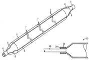
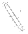
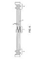
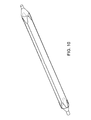
- FIG. 2 is a plan view of the inflated angioplasty balloon and non-deployable stent of FIG. 1 .
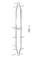
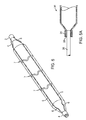
- FIG. 4 is a plan view of the non-deployable stent of FIG. 3 .
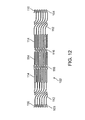
- FIG. 12 is an engineering drawing showing, in plan view, the layout of another embodiment of a non-deployable stent adapted to be used with an angioplasty balloon, in accordance with the present invention.
- the balloon 1 may be made of either nylon or nylon copolymer (compliant, non-puncture) or PET (high pressure, non-compliant) with a urethane, polymer, or other material and coating known in the art to provide tackiness and/or puncture resistance.
- the balloon may be a multi-layered balloon with a non-compliant inner layer to a most compliant outer layer or multilayered with similar material. For example, a inner most layer of PET, which provides a higher pressure balloon, surrounded by an outer layer of nylon, which provides a more puncture-resistant surface.
- the Nitinol structure 2 comprises a laser cut hypo tube that expands upon inflation of the balloon, but collapses upon deflation of the balloon because of the super-elastic properties of the Nitinol material, rather than remain expanded in the deployed condition, as would stents in general.
- each end of the four struts 5 has a sinusoidal type bend 6 that allows the laser cut hypo tube to expand longitudinally when the balloon 1 is inflated.
- the linear length of the sinusoidal type bends 6 is sized to accommodate the longitudinal expansion of the balloon 1 due to inflation.
- the strut or wire 5 cross sectional shape can be round, triangular, elliptical, oval, or rectangular. Preferred thickness of the struts 5 ranges from 0.003 to 0.010 inch.
- Catheter shafts to which the balloon and laser cut hypo tube are attached can have diameters ranging from 2.5 F to 8 F, and the distal end may be tapered and slightly less in diameter than the proximal end.
- the set includes one U-shaped connector for each strut (3 struts—a set of 3 U-shaped connectors; 4 struts—a set of 4 U-shaped connector; and so on).
- the number of U-shaped connector sets depends on the length of the balloon and thus, the length of the laser cut hypo tube. For a 20 mm length balloon, there is one set of U-shaped connectors spaced 10 mm from the end (at the halfway point along length of balloon).
- FIG. 12 is directed to another embodiment of a non-deployable stent 102 which can be used with a conventional balloon catheter, in accordance with the present invention.
- the stent of this embodiment preferably has a Nitinol structure, though other materials can be used as discussed supra, that incorporates bends for both radial and longitudinal expansion of the stent in response to radial and longitudinal expansion of the balloon during inflation, so that the stent 102 maintains the balloon in its intended position.
- the stent comprises a laser cut hypo tube that expands upon inflation of the balloon and collapses upon deflation of the balloon. Further, the stent is preferably secured to the balloon with some type of anchoring means.
- such anchoring means are utilized at the ends of the stent and around the neck of the balloon.
- anchoring means include an adhesive such as for example a UV adhesive, cyanoacrylate, or a two-part epoxy, RF heat welding, solvent bonding, or crimping or swaging the ends of the stent to the shaft.
- a mechanical anchoring means can be used to anchor the stent to the balloon. With such a means, a small sleeve 24 made of a similar material as the shaft 26 of the catheter is mounted over the ends 28 of the stent 30 and heat welded together where the ends of the stent are sandwiched between the shaft and the sleeve ( FIG. 5A ).
- FIG. 12 shows the hypo tube of the stent in an unrolled (flat) and non-extended state.
- the stent 102 has a proximal end 103 and a distal end 104 . At each end, there are cage mounted flanges 110 . These flanges can be used to attach the stent to the neck of the balloon. The flanges also spring open radially to permit insertion of the balloon during assembly. Between the ends, the stent 102 includes extension sections 112 , serpentine rings 114 and elongation links 116 .
- Serpentine rings 114 have a serpentine shape and allow the stent 102 to expand radially when a balloon in the stent is inflated. However, as the balloon expands, the serpentine rings 114 will shorten in length. Accordingly, extension sections 112 and elongation links 116 expand longitudinally to compensate for any shortening of the length of serpentine rings 114 .
- elongation links 116 have a z-shape, s-shape or accordion shape, as shown in FIG. 12 .
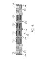
- FIG. 13 is an alternative embodiment showing a stent 202 having the same features as the stent in FIG. 12 except that stent 202 in FIG. 13 has elongated links 216 with a different pattern than the elongated links 116 in stent 102 of FIG. 12 . More specifically, elongated links 216 have a zig zag pattern. Stent 202 of FIG. 13 operates in a substantially similar manner to that of stent 102 in FIG. 12 .
- FIG. 13 also shows an example of possible dimensions, in inches, of each of the components of the stent 202 . These dimensions would also be used for each of the similar components in stent 102 in FIG. 12 .
Abstract
Description
where d is the diameter of the inflated balloon and n is the number of struts. The total length of the U-shaped bends (up and back) must exceed this length.
where L=length of balloon in mm. Other embodiments, such as those shown in
Claims (12)
Priority Applications (3)
| Application Number | Priority Date | Filing Date | Title |
|---|---|---|---|
| US11/292,426 US7931663B2 (en) | 2001-11-09 | 2005-12-01 | Balloon catheter with non-deployable stent |
| US13/022,489 US10086178B2 (en) | 2001-11-09 | 2011-02-07 | Balloon catheter with non-deployable stent |
| US13/489,250 US11571554B2 (en) | 2001-11-09 | 2012-06-05 | Balloon catheter with non-deployable stent |
Applications Claiming Priority (5)
| Application Number | Priority Date | Filing Date | Title |
|---|---|---|---|
| US34498201P | 2001-11-09 | 2001-11-09 | |
| US10/399,589 US7691119B2 (en) | 2001-11-09 | 2002-11-06 | Balloon catheter with non-deployable stent |
| PCT/US2002/035547 WO2003041760A2 (en) | 2001-11-09 | 2002-11-06 | Baloon catheter with non-deployable stent |
| US10/651,557 US20040111108A1 (en) | 2001-11-09 | 2003-08-29 | Balloon catheter with non-deployable stent |
| US11/292,426 US7931663B2 (en) | 2001-11-09 | 2005-12-01 | Balloon catheter with non-deployable stent |
Related Parent Applications (1)
| Application Number | Title | Priority Date | Filing Date |
|---|---|---|---|
| US10/651,557 Continuation US20040111108A1 (en) | 2001-11-09 | 2003-08-29 | Balloon catheter with non-deployable stent |
Related Child Applications (1)
| Application Number | Title | Priority Date | Filing Date |
|---|---|---|---|
| US13/022,489 Continuation US10086178B2 (en) | 2001-11-09 | 2011-02-07 | Balloon catheter with non-deployable stent |
Publications (2)
| Publication Number | Publication Date |
|---|---|
| US20060085025A1 US20060085025A1 (en) | 2006-04-20 |
| US7931663B2 true US7931663B2 (en) | 2011-04-26 |
Family
ID=34273385
Family Applications (4)
| Application Number | Title | Priority Date | Filing Date |
|---|---|---|---|
| US10/651,557 Abandoned US20040111108A1 (en) | 2001-11-09 | 2003-08-29 | Balloon catheter with non-deployable stent |
| US11/292,426 Active 2026-06-02 US7931663B2 (en) | 2001-11-09 | 2005-12-01 | Balloon catheter with non-deployable stent |
| US13/022,489 Expired - Lifetime US10086178B2 (en) | 2001-11-09 | 2011-02-07 | Balloon catheter with non-deployable stent |
| US13/489,250 Expired - Lifetime US11571554B2 (en) | 2001-11-09 | 2012-06-05 | Balloon catheter with non-deployable stent |
Family Applications Before (1)
| Application Number | Title | Priority Date | Filing Date |
|---|---|---|---|
| US10/651,557 Abandoned US20040111108A1 (en) | 2001-11-09 | 2003-08-29 | Balloon catheter with non-deployable stent |
Family Applications After (2)
| Application Number | Title | Priority Date | Filing Date |
|---|---|---|---|
| US13/022,489 Expired - Lifetime US10086178B2 (en) | 2001-11-09 | 2011-02-07 | Balloon catheter with non-deployable stent |
| US13/489,250 Expired - Lifetime US11571554B2 (en) | 2001-11-09 | 2012-06-05 | Balloon catheter with non-deployable stent |
Country Status (7)
| Country | Link |
|---|---|
| US (4) | US20040111108A1 (en) |
| EP (1) | EP1659989B1 (en) |
| JP (1) | JP4602977B2 (en) |
| AT (1) | ATE443497T1 (en) |
| DE (1) | DE602004023307D1 (en) |
| ES (1) | ES2330228T3 (en) |
| WO (1) | WO2005020855A1 (en) |
Cited By (26)
| Publication number | Priority date | Publication date | Assignee | Title |
|---|---|---|---|---|
| US20100042121A1 (en) * | 2008-03-21 | 2010-02-18 | Peter Schneider | Pre-angioplasty serration of atherosclerotic plaque enabling low-pressure balloon angioplasty and avoidance of stenting |
| US20110125247A1 (en) * | 2001-11-09 | 2011-05-26 | Angioscore, Inc. | Balloon catheter with non-deployable stent |
| US9173977B2 (en) | 2010-04-19 | 2015-11-03 | Angioscore, Inc. | Coating formulations for scoring or cutting balloon catheters |
| US9179936B2 (en) | 2012-02-08 | 2015-11-10 | Quattro Vascular Pte Ltd. | Constraining structure with non-linear axial struts |
| US9199066B2 (en) | 2010-03-12 | 2015-12-01 | Quattro Vascular Pte Ltd. | Device and method for compartmental vessel treatment |
| US9216033B2 (en) | 2012-02-08 | 2015-12-22 | Quattro Vascular Pte Ltd. | System and method for treating biological vessels |
| US9351756B2 (en) | 2010-09-21 | 2016-05-31 | Angioscore, Inc. | Method and system for treating valve stenosis |
| US9358042B2 (en) | 2013-03-13 | 2016-06-07 | The Spectranetics Corporation | Expandable member for perforation occlusion |
| US9375328B2 (en) | 2001-11-09 | 2016-06-28 | Angioscore, Inc. | Balloon catheter with non-deployable stent |
| US9393386B2 (en) | 2008-03-21 | 2016-07-19 | Cagent Vascular, Llc | Intravascular device |
| US9586031B2 (en) | 2005-05-11 | 2017-03-07 | Angioscore, Inc. | Methods and systems for delivering substances into luminal walls |
| US9808276B2 (en) | 2013-04-25 | 2017-11-07 | Invatec S.P.A. | Angioplasty balloon having selectively deployable cutting or scoring element and related methods |
| US20180104458A1 (en) * | 2016-10-17 | 2018-04-19 | Cook Medical Technologies Llc | Shape controlled balloon catheter |
| US9962529B2 (en) | 2003-01-21 | 2018-05-08 | Angioscore, Inc. | Apparatus and methods for treating hardened vascular lesions |
| US10117668B2 (en) | 2013-10-08 | 2018-11-06 | The Spectranetics Corporation | Balloon catheter with non-deployable stent having improved stability |
| US10166374B2 (en) | 2015-09-17 | 2019-01-01 | Cagent Vascular, Llc | Wedge dissectors for a medical balloon |
| US10220193B2 (en) | 2012-02-01 | 2019-03-05 | TriReme Medical, LLC | Device for compartmental dilatation of blood vessels |
| US10232148B2 (en) | 2014-11-17 | 2019-03-19 | TriReme Medical, LLC | Balloon catheter system and method of using same |
| US10449336B2 (en) | 2015-08-11 | 2019-10-22 | The Spectranetics Corporation | Temporary occlusions balloon devices and methods for preventing blood flow through a vascular perforation |
| US10471238B2 (en) | 2014-11-03 | 2019-11-12 | Cagent Vascular, Llc | Serration balloon |
| US10499892B2 (en) | 2015-08-11 | 2019-12-10 | The Spectranetics Corporation | Temporary occlusion balloon devices and methods for preventing blood flow through a vascular perforation |
| US10905863B2 (en) | 2016-11-16 | 2021-02-02 | Cagent Vascular, Llc | Systems and methods of depositing drug into tissue through serrations |
| US20210113820A1 (en) * | 2018-07-09 | 2021-04-22 | Goodman Co., Ltd. | Balloon catheter |
| US11219750B2 (en) | 2008-03-21 | 2022-01-11 | Cagent Vascular, Inc. | System and method for plaque serration |
| US11369779B2 (en) | 2018-07-25 | 2022-06-28 | Cagent Vascular, Inc. | Medical balloon catheters with enhanced pushability |
| US11738181B2 (en) | 2014-06-04 | 2023-08-29 | Cagent Vascular, Inc. | Cage for medical balloon |
Families Citing this family (34)
| Publication number | Priority date | Publication date | Assignee | Title |
|---|---|---|---|---|
| US20050021070A1 (en) * | 2003-01-21 | 2005-01-27 | Angioscore, Inc. | Methods and apparatus for manipulating vascular prostheses |
| US20050240148A1 (en) * | 2004-04-21 | 2005-10-27 | Scimed Life Systems, Inc. | Traction cutting balloon |
| WO2006034436A2 (en) | 2004-09-21 | 2006-03-30 | Stout Medical Group, L.P. | Expandable support device and method of use |
| DK1830915T3 (en) * | 2004-12-30 | 2009-02-16 | Cook Inc | Catheter construction with plaque cutting balloon |
| US20060178685A1 (en) * | 2004-12-30 | 2006-08-10 | Cook Incorporated | Balloon expandable plaque cutting device |
| US20060173487A1 (en) * | 2005-01-05 | 2006-08-03 | Cook Incorporated | Angioplasty cutting device and method for treating a stenotic lesion in a body vessel |
| JP5112295B2 (en) * | 2005-04-27 | 2013-01-09 | スタウト メディカル グループ,エル.ピー. | Expandable support and method of use |
| EP1903949A2 (en) | 2005-07-14 | 2008-04-02 | Stout Medical Group, L.P. | Expandable support device and method of use |
| US7708753B2 (en) | 2005-09-27 | 2010-05-04 | Cook Incorporated | Balloon catheter with extendable dilation wire |
| US8123770B2 (en) * | 2005-11-01 | 2012-02-28 | Cook Medical Technologies Llc | Angioplasty cutting device and method for treating a stenotic lesion in a body vessel |
| US20070213759A1 (en) * | 2006-03-08 | 2007-09-13 | Osborne Thomas A | Puncture resistant balloon catheter |
| WO2007131002A2 (en) | 2006-05-01 | 2007-11-15 | Stout Medical Group, L.P. | Expandable support device and method of use |
| US20100168714A1 (en) | 2007-03-06 | 2010-07-01 | Cook Incorpated | Therapeutic agent delivery system |
| US20090093794A1 (en) * | 2007-10-03 | 2009-04-09 | Tyco Healthcare Group Lp | Bolus tube assembly |
| US20090171283A1 (en) * | 2007-12-27 | 2009-07-02 | Cook Incorporated | Method of bonding a dilation element to a surface of an angioplasty balloon |
| WO2009114425A1 (en) | 2008-03-13 | 2009-09-17 | Cook Incorporated | Cutting balloon with connector and dilation element |
| EP2172242A1 (en) | 2008-10-03 | 2010-04-07 | National University of Ireland Galway | Intravascular Treatment Device |
| WO2010056895A1 (en) | 2008-11-12 | 2010-05-20 | Stout Medical Group, L.P. | Fixation device and method |
| US20100211176A1 (en) | 2008-11-12 | 2010-08-19 | Stout Medical Group, L.P. | Fixation device and method |
| US8535380B2 (en) | 2010-05-13 | 2013-09-17 | Stout Medical Group, L.P. | Fixation device and method |
| WO2012009409A1 (en) * | 2010-07-16 | 2012-01-19 | Abbott Cardiovascular Systems Inc. | Method and medical device having tissue engaging member for delivery of a therapeutic agent |
| WO2012009412A1 (en) * | 2010-07-16 | 2012-01-19 | Abbott Cardiovascular Systems Inc. | Medical device having tissue engaging member and method for delivery of a therapeutic agent |
| JP5634787B2 (en) * | 2010-08-04 | 2014-12-03 | 矢崎総業株式会社 | Crimp terminal |
| EP2608747A4 (en) | 2010-08-24 | 2015-02-11 | Flexmedex Llc | Support device and method for use |
| US9149286B1 (en) | 2010-11-12 | 2015-10-06 | Flexmedex, LLC | Guidance tool and method for use |
| CN106361407A (en) * | 2011-03-15 | 2017-02-01 | 亨利·威廉·勒普顿 | An anchoring device for anchoring a boring tool in a lumen or vessel |
| JP2014529445A (en) | 2011-08-23 | 2014-11-13 | フレックスメデックス,エルエルシー | Tissue removal apparatus and method |
| US10286190B2 (en) | 2013-12-11 | 2019-05-14 | Cook Medical Technologies Llc | Balloon catheter with dynamic vessel engaging member |
| US9956384B2 (en) | 2014-01-24 | 2018-05-01 | Cook Medical Technologies Llc | Articulating balloon catheter and method for using the same |
| US10314703B2 (en) | 2015-09-21 | 2019-06-11 | Edwards Lifesciences Corporation | Cylindrical implant and balloon |
| US11007061B2 (en) * | 2018-05-24 | 2021-05-18 | Edwards Lifesciences Corporation | Adjustable percutaneous heart valve repair system |
| WO2020144208A1 (en) * | 2019-01-09 | 2020-07-16 | Life Vascular Devices Biotech, S.L. | Scoring catheter |
| CN110496298A (en) * | 2019-09-17 | 2019-11-26 | 自贡市精神卫生中心 | A kind of side saccule urinary catheter of anti-clogging urine-leakage |
| CN111699016B (en) * | 2020-04-30 | 2021-09-03 | 广东博迈医疗科技股份有限公司 | Cutting device and cutting balloon |
Citations (88)
| Publication number | Priority date | Publication date | Assignee | Title |
|---|---|---|---|---|
| US2701559A (en) * | 1951-08-02 | 1955-02-08 | William A Cooper | Apparatus for exfoliating and collecting diagnostic material from inner walls of hollow viscera |
| US2854983A (en) * | 1957-10-31 | 1958-10-07 | Arnold M Baskin | Inflatable catheter |
| US4637396A (en) * | 1984-10-26 | 1987-01-20 | Cook, Incorporated | Balloon catheter |
| US4723549A (en) * | 1986-09-18 | 1988-02-09 | Wholey Mark H | Method and apparatus for dilating blood vessels |
| US4921484A (en) * | 1988-07-25 | 1990-05-01 | Cordis Corporation | Mesh balloon catheter device |
| US4950227A (en) * | 1988-11-07 | 1990-08-21 | Boston Scientific Corporation | Stent delivery system |
| US4998539A (en) * | 1987-12-18 | 1991-03-12 | Delsanti Gerard L | Method of using removable endo-arterial devices to repair detachments in the arterial walls |
| US5071407A (en) * | 1990-04-12 | 1991-12-10 | Schneider (U.S.A.) Inc. | Radially expandable fixation member |
| US5102417A (en) * | 1985-11-07 | 1992-04-07 | Expandable Grafts Partnership | Expandable intraluminal graft, and method and apparatus for implanting an expandable intraluminal graft |
| US5108416A (en) | 1990-02-13 | 1992-04-28 | C. R. Bard, Inc. | Stent introducer system |
| US5176693A (en) * | 1992-05-11 | 1993-01-05 | Interventional Technologies, Inc. | Balloon expandable atherectomy cutter |
| US5190058A (en) * | 1991-05-22 | 1993-03-02 | Medtronic, Inc. | Method of using a temporary stent catheter |
| US5222971A (en) * | 1990-10-09 | 1993-06-29 | Scimed Life Systems, Inc. | Temporary stent and methods for use and manufacture |
| US5449373A (en) * | 1994-03-17 | 1995-09-12 | Medinol Ltd. | Articulated stent |
| US5449372A (en) * | 1990-10-09 | 1995-09-12 | Scimed Lifesystems, Inc. | Temporary stent and methods for use and manufacture |
| US5456667A (en) * | 1993-05-20 | 1995-10-10 | Advanced Cardiovascular Systems, Inc. | Temporary stenting catheter with one-piece expandable segment |
| US5527282A (en) * | 1994-12-09 | 1996-06-18 | Segal; Jerome | Vascular dilatation device and method |
| US5571086A (en) * | 1992-11-02 | 1996-11-05 | Localmed, Inc. | Method and apparatus for sequentially performing multiple intraluminal procedures |
| US5607442A (en) | 1995-11-13 | 1997-03-04 | Isostent, Inc. | Stent with improved radiopacity and appearance characteristics |
| WO1998005377A1 (en) | 1996-08-02 | 1998-02-12 | Btg International Limited | Balloon catheter |
| US5730698A (en) * | 1995-05-09 | 1998-03-24 | Fischell; Robert E. | Balloon expandable temporary radioisotope stent system |
| US5755708A (en) * | 1994-12-09 | 1998-05-26 | Segal; Jerome | Mechanical apparatus and method for deployment of expandable prosthesis |
| US5755781A (en) * | 1996-08-06 | 1998-05-26 | Iowa-India Investments Company Limited | Embodiments of multiple interconnected stents |
| US5766238A (en) * | 1991-10-28 | 1998-06-16 | Advanced Cardiovascular Systems, Inc. | Expandable stents and method for making same |
| US5776141A (en) * | 1995-08-28 | 1998-07-07 | Localmed, Inc. | Method and apparatus for intraluminal prosthesis delivery |
| US5797935A (en) * | 1996-09-26 | 1998-08-25 | Interventional Technologies Inc. | Balloon activated forced concentrators for incising stenotic segments |
| US5868708A (en) * | 1997-05-07 | 1999-02-09 | Applied Medical Resources Corporation | Balloon catheter apparatus and method |
| US5868779A (en) | 1997-08-15 | 1999-02-09 | Ruiz; Carlos E. | Apparatus and methods for dilating vessels and hollow-body organs |
| US5904698A (en) * | 1997-06-10 | 1999-05-18 | Applied Medical Resources Corporation | Surgical shaving device for use within body conduits |
| US5994667A (en) | 1997-10-15 | 1999-11-30 | Scimed Life Systems, Inc. | Method and apparatus for laser cutting hollow workpieces |
| US6036689A (en) * | 1998-09-24 | 2000-03-14 | Tu; Lily Chen | Ablation device for treating atherosclerotic tissues |
| US6053913A (en) * | 1998-09-10 | 2000-04-25 | Tu; Lily Chen | Rapid exchange stented balloon catheter having ablation capabilities |
| US6071286A (en) | 1997-02-19 | 2000-06-06 | Mawad; Michel E. | Combination angioplasty balloon/stent deployment device |
| US6071285A (en) | 1996-03-25 | 2000-06-06 | Lashinski; Robert D. | Rapid exchange folded balloon catheter and stent delivery system |
| US6077298A (en) * | 1999-02-20 | 2000-06-20 | Tu; Lily Chen | Expandable/retractable stent and methods thereof |
| US6106548A (en) | 1997-02-07 | 2000-08-22 | Endosystems Llc | Non-foreshortening intraluminal prosthesis |
| US6117104A (en) | 1998-09-08 | 2000-09-12 | Advanced Cardiovascular Systems, Inc. | Stent deployment system and method of use |
| US6146323A (en) * | 1999-05-14 | 2000-11-14 | Isostent, Inc. | Delivery catheter for a radioisotope stent |
| US6152944A (en) | 1997-03-05 | 2000-11-28 | Scimed Life Systems, Inc. | Catheter with removable balloon protector and stent delivery system with removable stent protector |
| US6190403B1 (en) * | 1998-11-13 | 2001-02-20 | Cordis Corporation | Low profile radiopaque stent with increased longitudinal flexibility and radial rigidity |
| US6203569B1 (en) * | 1996-01-04 | 2001-03-20 | Bandula Wijay | Flexible stent |
| US6206910B1 (en) | 1997-09-11 | 2001-03-27 | Wake Forest University | Compliant intraluminal stents |
| US20010001823A1 (en) * | 1996-08-09 | 2001-05-24 | Ryan Timothy James | Soluble fixation device and method for stent delivery catheters |
| US6245040B1 (en) * | 1994-01-14 | 2001-06-12 | Cordis Corporation | Perfusion balloon brace and method of use |
| US20010007082A1 (en) * | 1996-08-23 | 2001-07-05 | Dusbabek Andrew J. | Stent delivery system having stent securement apparatus |
| US6258087B1 (en) * | 1998-02-19 | 2001-07-10 | Curon Medical, Inc. | Expandable electrode assemblies for forming lesions to treat dysfunction in sphincters and adjoining tissue regions |
| US20010012950A1 (en) * | 1997-10-01 | 2001-08-09 | Srinivas Nishtala | Dilation systems and related methods |
| US20010016753A1 (en) * | 1996-08-23 | 2001-08-23 | Caprio Fernando Di | Balloon catheter with stent securement means |
| US6309414B1 (en) * | 1997-11-04 | 2001-10-30 | Sorin Biomedica Cardio S.P.A. | Angioplasty stents |
| US6312459B1 (en) | 1999-06-30 | 2001-11-06 | Advanced Cardiovascular Systems, Inc. | Stent design for use in small vessels |
| US6325813B1 (en) * | 1998-08-18 | 2001-12-04 | Scimed Life Systems, Inc. | Method and apparatus for stabilizing vascular wall |
| US6325779B1 (en) | 1998-08-21 | 2001-12-04 | Biotronik Mess-Und Therapiegeraete Gmbh & Co. Ingenieurbuero Berlin | Balloon catheter |
| EP1179323A2 (en) | 2000-08-10 | 2002-02-13 | Cordis Corporation | Low profile radio-opaque stent |
| US20020038144A1 (en) | 2000-02-15 | 2002-03-28 | Trout Hugh H. | Temporary stent assembly for use in a surgical procedure |
| US6371961B1 (en) | 1996-01-18 | 2002-04-16 | Cook Incorporated | Rapid exchange stent delivery balloon catheter |
| US20020045930A1 (en) * | 1995-12-14 | 2002-04-18 | Burg Erik Van Der | Stent-graft deployment apparatus and method |
| US6416539B1 (en) * | 1997-06-30 | 2002-07-09 | Medex, Inc. | Controlled length intraluminal implant |
| US20020111633A1 (en) * | 1994-06-06 | 2002-08-15 | Meadox Medicals, Inc. | Catheter with stent and method for the production of a catheter with stent |
| US6475234B1 (en) | 1998-10-26 | 2002-11-05 | Medinol, Ltd. | Balloon expandable covered stents |
| US20020165599A1 (en) | 2001-05-01 | 2002-11-07 | Max Nasralla | Variable form stent and deployment arrangement for use therewith |
| US6478807B1 (en) * | 2000-06-08 | 2002-11-12 | Advanced Cardiovascular Systems, Inc. | Pre-formed expandable member having grooves |
| US20030023200A1 (en) * | 1999-03-01 | 2003-01-30 | Coaxia, Inc. | Partial aortic occlusion devices and methods for cerebral perfusion augmentation |
| US20030028235A1 (en) * | 2001-07-31 | 2003-02-06 | Mcintosh Winnette S. | Rapid exchange delivery system for self-expanding stent |
| US6540722B1 (en) * | 1999-12-30 | 2003-04-01 | Advanced Cardiovascular Systems, Inc. | Embolic protection devices |
| US20030074046A1 (en) | 2001-08-27 | 2003-04-17 | Jacob Richter | Single operator stenting system |
| US6551310B1 (en) * | 1999-11-16 | 2003-04-22 | Robert A. Ganz | System and method of treating abnormal tissue in the human esophagus |
| WO2003041760A2 (en) | 2001-11-09 | 2003-05-22 | Novoste Corporation | Baloon catheter with non-deployable stent |
| US6569180B1 (en) | 2000-06-02 | 2003-05-27 | Avantec Vascular Corporation | Catheter having exchangeable balloon |
| US20030105509A1 (en) | 1995-11-13 | 2003-06-05 | Yue-Teh Jang | Catheter system having imaging, balloon angioplasty, and stent deployment capabilities, and method of use for guided stent deployment |
| US20030149468A1 (en) | 2000-05-26 | 2003-08-07 | Wallsten Hans I | Balloon catheter |
| US6605107B1 (en) * | 1995-06-05 | 2003-08-12 | Avantec Vascular Corporation | Radially expansible vessel scaffolds mounted over balloons |
| US20030153870A1 (en) * | 2002-02-14 | 2003-08-14 | Intella Interventional Systems, Inc. | Balloon catheter for creating a longitudinal channel in a lesion and method |
| US6613072B2 (en) * | 1994-09-08 | 2003-09-02 | Gore Enterprise Holdings, Inc. | Procedures for introducing stents and stent-grafts |
| US20030171799A1 (en) | 1998-04-21 | 2003-09-11 | Lee Jeong S. | Stent deploying catheter system and balloon catheter |
| US6626861B1 (en) * | 1998-04-22 | 2003-09-30 | Applied Medical Resources | Balloon catheter apparatus and method |
| US20030187494A1 (en) * | 2000-02-18 | 2003-10-02 | Alessandro Loaldi | Endolumenal device for delivering and deploying an endolumenal expandable prosthesis |
| US20030195609A1 (en) | 2002-04-10 | 2003-10-16 | Scimed Life Systems, Inc. | Hybrid stent |
| US20030199970A1 (en) * | 1998-03-30 | 2003-10-23 | Conor Medsystems, Inc. | Expandable medical device for delivery of beneficial agent |
| US20030199988A1 (en) | 1993-02-19 | 2003-10-23 | Scimed Life Systems, Inc. | Method and device for inserting and withdrawing a two piece stent across a constricting anatomic structure |
| US20030208244A1 (en) | 2002-04-26 | 2003-11-06 | Medtronic, Inc. | Voltage/current regulator improvements for an implantable medical device |
| US6656351B2 (en) * | 2001-08-31 | 2003-12-02 | Advanced Cardiovascular Systems, Inc. | Embolic protection devices one way porous membrane |
| US6695813B1 (en) * | 1999-12-30 | 2004-02-24 | Advanced Cardiovascular Systems, Inc. | Embolic protection devices |
| US20040143287A1 (en) * | 2003-01-21 | 2004-07-22 | Angioscore, Inc. | Apparatus and methods for treating hardened vascular lesions |
| US6840950B2 (en) * | 2001-02-20 | 2005-01-11 | Scimed Life Systems, Inc. | Low profile emboli capture device |
| US6872206B2 (en) * | 1998-02-19 | 2005-03-29 | Curon Medical, Inc. | Methods for treating the cardia of the stomach |
| US20060149308A1 (en) | 2004-12-30 | 2006-07-06 | Cook Incorporated | Catheter assembly with plaque cutting balloon |
| US20060184191A1 (en) | 2005-02-11 | 2006-08-17 | Boston Scientific Scimed, Inc. | Cutting balloon catheter having increased flexibility regions |
| US7354445B2 (en) * | 2003-12-15 | 2008-04-08 | Medtronic Vascular Inc. | Embolic containment system with asymmetric frictional control |
Family Cites Families (271)
| Publication number | Priority date | Publication date | Assignee | Title |
|---|---|---|---|---|
| US3045677A (en) | 1960-05-03 | 1962-07-24 | American Cystoscope Makers Inc | Inflatable balloon catheter |
| US3467101A (en) | 1965-09-30 | 1969-09-16 | Edwards Lab Inc | Balloon catheter |
| US3825013A (en) | 1973-03-12 | 1974-07-23 | Mcm Hospital Supplies Inc | Balloon catheter |
| US4327736A (en) | 1979-11-20 | 1982-05-04 | Kanji Inoue | Balloon catheter |
| US4483340A (en) | 1980-10-20 | 1984-11-20 | Thomas J. Fogarty | Dilatation catheter |
| US4456011A (en) | 1980-12-22 | 1984-06-26 | Irene Warnecke | Balloon-catheter |
| US4604762A (en) | 1981-02-13 | 1986-08-12 | Thoratec Laboratories Corporation | Arterial graft prosthesis |
| CH659166GA3 (en) | 1985-10-07 | 1987-01-15 | ||
| US4733665C2 (en) | 1985-11-07 | 2002-01-29 | Expandable Grafts Partnership | Expandable intraluminal graft and method and apparatus for implanting an expandable intraluminal graft |
| US4649922A (en) | 1986-01-23 | 1987-03-17 | Wiktor Donimik M | Catheter arrangement having a variable diameter tip and spring prosthesis |
| US5350395A (en) | 1986-04-15 | 1994-09-27 | Yock Paul G | Angioplasty apparatus facilitating rapid exchanges |
| US4838853A (en) | 1987-02-05 | 1989-06-13 | Interventional Technologies Inc. | Apparatus for trimming meniscus |
| US4796629A (en) | 1987-06-03 | 1989-01-10 | Joseph Grayzel | Stiffened dilation balloon catheter device |
| US4969458A (en) | 1987-07-06 | 1990-11-13 | Medtronic, Inc. | Intracoronary stent and method of simultaneous angioplasty and stent implant |
| US5133732A (en) | 1987-10-19 | 1992-07-28 | Medtronic, Inc. | Intravascular stent |
| US4895166A (en) | 1987-11-23 | 1990-01-23 | Interventional Technologies, Inc. | Rotatable cutter for the lumen of a blood vesel |
| US4887613A (en) | 1987-11-23 | 1989-12-19 | Interventional Technologies Inc. | Cutter for atherectomy device |
| US4942788A (en) | 1987-11-23 | 1990-07-24 | Interventional Technologies, Inc. | Method of manufacturing a cutter for atherectomy device |
| US5423745A (en) | 1988-04-28 | 1995-06-13 | Research Medical, Inc. | Irregular surface balloon catheters for body passageways and methods of use |
| DE68926862T2 (en) | 1988-10-28 | 1996-11-21 | Kanji Inoue | Balloon catheter assembly |
| US5904679A (en) | 1989-01-18 | 1999-05-18 | Applied Medical Resources Corporation | Catheter with electrosurgical cutter |
| US5628746A (en) | 1989-01-18 | 1997-05-13 | Applied Medical Resources Corporation | Dilatation catheter assembly with cutting element and method of using the same |
| US4986807A (en) | 1989-01-23 | 1991-01-22 | Interventional Technologies, Inc. | Atherectomy cutter with radially projecting blade |
| EP0638327B1 (en) | 1989-01-30 | 2008-08-20 | C.R. Bard, Inc. | Rapidly exchangeable coronary catheter |
| US4976711A (en) | 1989-04-13 | 1990-12-11 | Everest Medical Corporation | Ablation catheter with selectively deployable electrodes |
| US5116318A (en) | 1989-06-06 | 1992-05-26 | Cordis Corporation | Dilatation balloon within an elastic sleeve |
| JP3036835B2 (en) | 1989-08-18 | 2000-04-24 | イーブイアイ コーポレイション | Catheter atherotome |
| US5263963A (en) | 1989-09-08 | 1993-11-23 | Advanced Cardiovascular Systems, Inc. | Expandable cage catheter for repairing a damaged blood vessel |
| US4986830A (en) | 1989-09-22 | 1991-01-22 | Schneider (U.S.A.) Inc. | Valvuloplasty catheter with balloon which remains stable during inflation |
| US5062648A (en) | 1989-09-26 | 1991-11-05 | Interventional Technologies, Inc. | Seal for rotating torque tube with seal valve |
| US5026384A (en) | 1989-11-07 | 1991-06-25 | Interventional Technologies, Inc. | Atherectomy systems and methods |
| US5019088A (en) | 1989-11-07 | 1991-05-28 | Interventional Technologies Inc. | Ovoid atherectomy cutter |
| US5062384A (en) | 1989-11-13 | 1991-11-05 | Mfm Technology, Inc. | Vacuum chuck rotary seal |
| US5019089A (en) | 1989-12-07 | 1991-05-28 | Interventional Technologies Inc. | Atherectomy advancing probe and method of use |
| US5304121A (en) | 1990-12-28 | 1994-04-19 | Boston Scientific Corporation | Drug delivery system making use of a hydrogel polymer coating |
| US5674192A (en) | 1990-12-28 | 1997-10-07 | Boston Scientific Corporation | Drug delivery |
| US5003918A (en) | 1989-12-28 | 1991-04-02 | Interventional Technologies, Inc. | Apparatus for manufacturing atherectomy torque tubes |
| US5342301A (en) | 1992-08-13 | 1994-08-30 | Advanced Polymers Incorporated | Multi-lumen balloons and catheters made therewith |
| US5624392A (en) | 1990-05-11 | 1997-04-29 | Saab; Mark A. | Heat transfer catheters and methods of making and using same |
| US5120322A (en) | 1990-06-13 | 1992-06-09 | Lathrotec, Inc. | Method and apparatus for treatment of fibrotic lesions |
| US5196024A (en) * | 1990-07-03 | 1993-03-23 | Cedars-Sinai Medical Center | Balloon catheter with cutting edge |
| US5320634A (en) | 1990-07-03 | 1994-06-14 | Interventional Technologies, Inc. | Balloon catheter with seated cutting edges |
| US5101682A (en) | 1990-07-06 | 1992-04-07 | Interventional Technologies, Inc. | Reinforced tubing |
| US5098440A (en) | 1990-08-14 | 1992-03-24 | Cordis Corporation | Object retrieval method and apparatus |
| US5100423A (en) | 1990-08-21 | 1992-03-31 | Medical Engineering & Development Institute, Inc. | Ablation catheter |
| US5350101A (en) | 1990-11-20 | 1994-09-27 | Interventional Technologies Inc. | Device for advancing a rotatable tube |
| US5112345A (en) | 1990-12-17 | 1992-05-12 | Interventional Technologies | Atherectomy cutter with arcuate blades |
| US5102402A (en) | 1991-01-04 | 1992-04-07 | Medtronic, Inc. | Releasable coatings on balloon catheters |
| US5295958A (en) | 1991-04-04 | 1994-03-22 | Shturman Cardiology Systems, Inc. | Method and apparatus for in vivo heart valve decalcification |
| US5181911A (en) | 1991-04-22 | 1993-01-26 | Shturman Technologies, Inc. | Helical balloon perfusion angioplasty catheter |
| US5458568A (en) | 1991-05-24 | 1995-10-17 | Cortrak Medical, Inc. | Porous balloon for selective dilatation and drug delivery |
| US5217474A (en) | 1991-07-15 | 1993-06-08 | Zacca Nadim M | Expandable tip atherectomy method and apparatus |
| RU2093087C1 (en) | 1991-07-15 | 1997-10-20 | М.Закка Надим | Apparatus and method for treating occlusion in vessel (alternative embodiments), method for removing from vessel |
| EP0549100A1 (en) | 1991-12-20 | 1993-06-30 | Interventional Technologies Inc | Catheter balloon formed from a polymeric composite |
| US5224949A (en) | 1992-01-13 | 1993-07-06 | Interventional Technologies, Inc. | Camming device |
| US5224945A (en) | 1992-01-13 | 1993-07-06 | Interventional Technologies, Inc. | Compressible/expandable atherectomy cutter |
| US5192291A (en) | 1992-01-13 | 1993-03-09 | Interventional Technologies, Inc. | Rotationally expandable atherectomy cutter assembly |
| US5742019A (en) | 1992-01-13 | 1998-04-21 | Interventional Technologies Inc. | Method for manufacturing an atherectomy cutter having a positive angle of attack |
| US5209727A (en) | 1992-01-29 | 1993-05-11 | Interventional Technologies, Inc. | Guide wire with integral angioplasty balloon |
| US5226887A (en) | 1992-02-07 | 1993-07-13 | Interventional Technologies, Inc. | Collapsible folding angioplasty balloon |
| US5295959A (en) * | 1992-03-13 | 1994-03-22 | Medtronic, Inc. | Autoperfusion dilatation catheter having a bonded channel |
| US5282823A (en) | 1992-03-19 | 1994-02-01 | Medtronic, Inc. | Intravascular radially expandable stent |
| US5295493A (en) | 1992-03-19 | 1994-03-22 | Interventional Technologies, Inc. | Anatomical guide wire |
| US5306250A (en) * | 1992-04-02 | 1994-04-26 | Indiana University Foundation | Method and apparatus for intravascular drug delivery |
| US5243997A (en) | 1992-09-14 | 1993-09-14 | Interventional Technologies, Inc. | Vibrating device for a guide wire |
| US5443078A (en) | 1992-09-14 | 1995-08-22 | Interventional Technologies, Inc. | Method for advancing a guide wire |
| US5524635A (en) | 1992-09-14 | 1996-06-11 | Interventional Technologies Inc. | Apparatus for advancing a guide wire |
| US5460607A (en) | 1992-09-30 | 1995-10-24 | Nippon Zeon Co., Ltd. | Balloon catheter |
| US5490859A (en) | 1992-11-13 | 1996-02-13 | Scimed Life Systems, Inc. | Expandable intravascular occlusion material removal devices and methods of use |
| US5501694A (en) | 1992-11-13 | 1996-03-26 | Scimed Life Systems, Inc. | Expandable intravascular occlusion material removal devices and methods of use |
| US5318576A (en) | 1992-12-16 | 1994-06-07 | Plassche Jr Walter M | Endovascular surgery systems |
| US5308356A (en) | 1993-02-25 | 1994-05-03 | Blackshear Jr Perry L | Passive perfusion angioplasty catheter |
| DK171747B1 (en) | 1993-03-02 | 1997-05-05 | Metra Aps | dilatation catheter |
| WO1994023787A1 (en) | 1993-04-22 | 1994-10-27 | Rammler David H | Sampling balloon catheter |
| US5344419A (en) | 1993-04-23 | 1994-09-06 | Wayne State University | Apparatus and method for making a diffusing tip in a balloon catheter system |
| JP3655920B2 (en) | 1993-04-29 | 2005-06-02 | シメッド ライフ システムズ インコーポレイテッド | Expandable vascular occlusion removal device |
| CA2118886C (en) | 1993-05-07 | 1998-12-08 | Dennis Vigil | Method and apparatus for dilatation of a stenotic vessel |
| ES2112931T3 (en) | 1993-06-23 | 1998-04-16 | Mihai Iacob | PERFUSION CATHETER FOR ANGIOPLASTY. |
| IT1265179B1 (en) | 1993-11-12 | 1996-10-31 | Elcon Instr Srl | DEVICE FOR INTERCONNECTION BETWEEN CIRCUITERIES IN INDUSTRIAL APPLICATIONS |
| US5545132A (en) | 1993-12-21 | 1996-08-13 | C. R. Bard, Inc. | Helically grooved balloon for dilatation catheter and method of using |
| RU2147213C1 (en) | 1994-01-26 | 2000-04-10 | А. Рейли Марк | Improved filled device for use in surgical protocol as applied to bone fixation |
| US5891090A (en) | 1994-03-14 | 1999-04-06 | Advanced Cardiovascular Systems, Inc. | Perfusion dilatation catheter with expanded support coil |
| US5733303A (en) | 1994-03-17 | 1998-03-31 | Medinol Ltd. | Flexible expandable stent |
| US5562620A (en) | 1994-04-01 | 1996-10-08 | Localmed, Inc. | Perfusion shunt device having non-distensible pouch for receiving angioplasty balloon |
| US5456666A (en) | 1994-04-26 | 1995-10-10 | Boston Scientific Corp | Medical balloon folding into predetermined shapes and method |
| US5810767A (en) | 1994-05-11 | 1998-09-22 | Localmed, Inc. | Method and apparatus for pressurized intraluminal drug delivery |
| WO1996000242A1 (en) | 1994-06-24 | 1996-01-04 | Human Genome Sciences, Inc. | Retinoic acid receptor epsilon |
| US5470314A (en) | 1994-07-22 | 1995-11-28 | Walinsky; Paul | Perfusion balloon catheter with differential compliance |
| US5575816A (en) | 1994-08-12 | 1996-11-19 | Meadox Medicals, Inc. | High strength and high density intraluminal wire stent |
| US5707385A (en) | 1994-11-16 | 1998-01-13 | Advanced Cardiovascular Systems, Inc. | Drug loaded elastic membrane and method for delivery |
| US5620457A (en) | 1994-11-23 | 1997-04-15 | Medinol Ltd. | Catheter balloon |
| US5628755A (en) | 1995-02-20 | 1997-05-13 | Schneider (Europe) A.G. | Balloon catheter and stent delivery system |
| CA2157697C (en) | 1995-01-10 | 2007-03-13 | Banning Gray Lary | Vascular incisor/dilator |
| NL9500468A (en) | 1995-03-08 | 1996-10-01 | Cordis Europ | Balloon catheter and method of making it. |
| US5624433A (en) * | 1995-04-24 | 1997-04-29 | Interventional Technologies Inc. | Angioplasty balloon with light incisor |
| US5556408A (en) | 1995-04-27 | 1996-09-17 | Interventional Technologies Inc. | Expandable and compressible atherectomy cutter |
| NL1000413C2 (en) | 1995-05-22 | 1996-11-25 | Cordis Europ | Balloon catheter with balloon protection jacket. |
| US5766201A (en) | 1995-06-07 | 1998-06-16 | Boston Scientific Corporation | Expandable catheter |
| EP0835075A4 (en) | 1995-06-30 | 1999-06-23 | Boston Scient Corp | Ultrasound imaging catheter with a cutting element |
| US5713863A (en) | 1996-01-11 | 1998-02-03 | Interventional Technologies Inc. | Catheter with fluid medication injectors |
| US5746716A (en) | 1995-07-10 | 1998-05-05 | Interventional Technologies Inc. | Catheter for injecting fluid medication into an arterial wall |
| US6102904A (en) | 1995-07-10 | 2000-08-15 | Interventional Technologies, Inc. | Device for injecting fluid into a wall of a blood vessel |
| PL184769B1 (en) | 1995-07-25 | 2002-12-31 | Medstent Inc | Expandible stent's mass |
| US5556382A (en) | 1995-08-29 | 1996-09-17 | Scimed Life Systems, Inc. | Balloon perfusion catheter |
| US5556405A (en) | 1995-10-13 | 1996-09-17 | Interventional Technologies Inc. | Universal dilator with reciprocal incisor |
| US6287336B1 (en) | 1995-10-16 | 2001-09-11 | Medtronic, Inc. | Variable flexibility stent |
| US5840008A (en) | 1995-11-13 | 1998-11-24 | Localmed, Inc. | Radiation emitting sleeve catheter and methods |
| US5697944A (en) | 1995-11-15 | 1997-12-16 | Interventional Technologies Inc. | Universal dilator with expandable incisor |
| DE19610461C2 (en) | 1996-03-16 | 1999-02-11 | Osypka Peter | Catheter with an insertion tube |
| US5718684A (en) * | 1996-05-24 | 1998-02-17 | Gupta; Mukesh | Multi-lobed balloon catheter |
| US5697971A (en) | 1996-06-11 | 1997-12-16 | Fischell; Robert E. | Multi-cell stent with cells having differing characteristics |
| US5735816A (en) | 1996-07-23 | 1998-04-07 | Medtronic, Inc. | Spiral sheath retainer for autoperfusion dilatation catheter balloon |
| US7252650B1 (en) * | 1996-08-02 | 2007-08-07 | Ranier Limited | Balloon catheter |
| US6156265A (en) | 1996-08-19 | 2000-12-05 | Sumitomo Electric Industries, Ltd. | Powder compacting apparatus and method of forming helical gear wheel using said powder compacting apparatus |
| CA2213015A1 (en) | 1996-08-23 | 1998-02-23 | Arterial Vascular Engineering, Inc. | A profiled stent and method of manufacture |
| CA2209366C (en) | 1996-09-13 | 2004-11-02 | Interventional Technologies, Inc. | Incisor-dilator with tapered balloon |
| US6555292B1 (en) | 1996-09-24 | 2003-04-29 | Misty Huang | Liquid photopolymer useful in fabricating printing plates which are resistant to solvent based ink |
| US6117153A (en) | 1996-10-03 | 2000-09-12 | Interventional Technologies, Inc. | Neovascularization catheter |
| US5879342A (en) | 1996-10-21 | 1999-03-09 | Kelley; Gregory S. | Flexible and reinforced tubing |
| US6835203B1 (en) | 1996-11-04 | 2004-12-28 | Advanced Stent Technologies, Inc. | Extendible stent apparatus |
| US5713913A (en) | 1996-11-12 | 1998-02-03 | Interventional Technologies Inc. | Device and method for transecting a coronary artery |
| US5916166A (en) | 1996-11-19 | 1999-06-29 | Interventional Technologies, Inc. | Medical guidewire with fully hardened core |
| US5807355A (en) | 1996-12-09 | 1998-09-15 | Advanced Cardiovascular Systems, Inc. | Catheter with rapid exchange and OTW operative modes |
| US6332880B1 (en) | 1996-12-19 | 2001-12-25 | Ep Technologies, Inc. | Loop structures for supporting multiple electrode elements |
| US5868719A (en) | 1997-01-15 | 1999-02-09 | Boston Scientific Corporation | Drug delivery balloon catheter device |
| JP2001512334A (en) | 1997-02-12 | 2001-08-21 | プロリフィックス メディカル,インコーポレイテッド | Equipment for removing material from stents |
| US6554795B2 (en) | 1997-03-06 | 2003-04-29 | Medtronic Ave, Inc. | Balloon catheter and method of manufacture |
| US5792144A (en) | 1997-03-31 | 1998-08-11 | Cathco, Inc. | Stent delivery catheter system |
| US5902475A (en) | 1997-04-08 | 1999-05-11 | Interventional Technologies, Inc. | Method for manufacturing a stent |
| US5868783A (en) | 1997-04-16 | 1999-02-09 | Numed, Inc. | Intravascular stent with limited axial shrinkage |
| US6221467B1 (en) | 1997-06-03 | 2001-04-24 | Scimed Life Systems, Inc. | Coating gradient for lubricious coatings on balloon catheters |
| JP3645399B2 (en) * | 1997-06-09 | 2005-05-11 | 住友金属工業株式会社 | Endovascular stent |
| EP0884029B1 (en) | 1997-06-13 | 2004-12-22 | Gary J. Becker | Expandable intraluminal endoprosthesis |
| US6306166B1 (en) | 1997-08-13 | 2001-10-23 | Scimed Life Systems, Inc. | Loading and release of water-insoluble drugs |
| US6592548B2 (en) | 1997-09-18 | 2003-07-15 | Iowa-India Investments Company Limited Of Douglas | Delivery mechanism for balloons, drugs, stents and other physical/mechanical agents and method of use |
| US6361545B1 (en) | 1997-09-26 | 2002-03-26 | Cardeon Corporation | Perfusion filter catheter |
| AU1190699A (en) | 1997-10-20 | 1999-05-10 | Robert D. Bersin | Helical spiral balloon catheter |
| US6224625B1 (en) | 1997-10-27 | 2001-05-01 | Iowa-India Investments Company Limited | Low profile highly expandable stent |
| US6013055A (en) | 1997-11-13 | 2000-01-11 | Boston Scientific Corporation | Catheter balloon having selected folding characteristics |
| US6330884B1 (en) | 1997-11-14 | 2001-12-18 | Transvascular, Inc. | Deformable scaffolding multicellular stent |
| US6319229B1 (en) | 1998-02-19 | 2001-11-20 | Medtronic Percusurge, Inc. | Balloon catheter and method of manufacture |
| US6540693B2 (en) | 1998-03-03 | 2003-04-01 | Senorx, Inc. | Methods and apparatus for securing medical instruments to desired locations in a patients body |
| US6241762B1 (en) | 1998-03-30 | 2001-06-05 | Conor Medsystems, Inc. | Expandable medical device with ductile hinges |
| US6306151B1 (en) | 1998-03-31 | 2001-10-23 | Interventional Technologies Inc. | Balloon with reciprocating stent incisor |
| US6364856B1 (en) | 1998-04-14 | 2002-04-02 | Boston Scientific Corporation | Medical device with sponge coating for controlled drug release |
| US20010001113A1 (en) * | 1998-04-21 | 2001-05-10 | Florencia Lim | Balloon catheter |
| US6450989B2 (en) | 1998-04-27 | 2002-09-17 | Artemis Medical, Inc. | Dilating and support apparatus with disease inhibitors and methods for use |
| FR2777771B1 (en) | 1998-04-27 | 2000-08-25 | Microval | TUBULAR AND FLEXIBLE VASCULAR ENDOPROSTHESIS |
| US6780199B2 (en) | 1998-05-15 | 2004-08-24 | Advanced Cardiovascular Systems, Inc. | Enhanced stent delivery system |
| AU764958B2 (en) | 1998-05-15 | 2003-09-04 | X Technologies, Inc. | Enhanced balloon dilatation system |
| US6447501B1 (en) | 1998-05-15 | 2002-09-10 | X Technologies Inc. | Enhanced stent delivery system |
| US6206283B1 (en) | 1998-12-23 | 2001-03-27 | At&T Corp. | Method and apparatus for transferring money via a telephone call |
| US6416494B1 (en) | 1998-06-11 | 2002-07-09 | Infinity Extrusion & Engineering, Inc. | Semi-compliant catheter balloons and methods of manufacture thereof |
| US5987661A (en) | 1998-06-25 | 1999-11-23 | Sportsstuff, Inc. | Inflatable swimming pool and supporting net |
| US6261319B1 (en) | 1998-07-08 | 2001-07-17 | Scimed Life Systems, Inc. | Stent |
| US6136011A (en) | 1998-07-14 | 2000-10-24 | Advanced Cardiovascular Systems, Inc. | Stent delivery system and method of use |
| US6036708A (en) | 1998-08-13 | 2000-03-14 | Advanced Cardiovascular Systems, Inc. | Cutting stent with flexible tissue extractor |
| US6036686A (en) * | 1998-08-17 | 2000-03-14 | Brymill Corporation | Cryosurgical instrument with grip |
| US6319251B1 (en) | 1998-09-24 | 2001-11-20 | Hosheng Tu | Medical device and methods for treating intravascular restenosis |
| US5919200A (en) | 1998-10-09 | 1999-07-06 | Hearten Medical, Inc. | Balloon catheter for abrading a patent foramen ovale and method of using the balloon catheter |
| US6123718A (en) | 1998-11-02 | 2000-09-26 | Polymerex Medical Corp. | Balloon catheter |
| US6289568B1 (en) | 1998-11-16 | 2001-09-18 | Cordis Corporation | Method for making a balloon catheter stent deployment system |
| US6355059B1 (en) | 1998-12-03 | 2002-03-12 | Medinol, Ltd. | Serpentine coiled ladder stent |
| US6129706A (en) | 1998-12-10 | 2000-10-10 | Janacek; Jaroslav | Corrugated catheter balloon |
| US6022359A (en) * | 1999-01-13 | 2000-02-08 | Frantzen; John J. | Stent delivery system featuring a flexible balloon |
| US6210392B1 (en) | 1999-01-15 | 2001-04-03 | Interventional Technologies, Inc. | Method for treating a wall of a blood vessel |
| US6258099B1 (en) | 1999-03-31 | 2001-07-10 | Scimed Life Systems, Inc. | Stent security balloon/balloon catheter |
| US6325825B1 (en) | 1999-04-08 | 2001-12-04 | Cordis Corporation | Stent with variable wall thickness |
| WO2000067825A1 (en) | 1999-05-07 | 2000-11-16 | Microheart, Inc. | Apparatus and method for delivering therapeutic and diagnostic agents |
| US6193686B1 (en) | 1999-06-30 | 2001-02-27 | Advanced Cardiovascular Systems, Inc. | Catheter with enhanced flexibility |
| NL1012527C2 (en) | 1999-07-06 | 2001-01-09 | Cordis Europ | Balloon catheter with tear line. |
| US6585757B1 (en) * | 1999-09-15 | 2003-07-01 | Advanced Cardiovascular Systems, Inc. | Endovascular stent with radiopaque spine |
| US6454775B1 (en) | 1999-12-06 | 2002-09-24 | Bacchus Vascular Inc. | Systems and methods for clot disruption and retrieval |
| US6450988B1 (en) | 1999-12-29 | 2002-09-17 | Advanced Cardiovascular Systems, Inc. | Centering catheter with improved perfusion |
| US6471979B2 (en) | 1999-12-29 | 2002-10-29 | Estrogen Vascular Technology, Llc | Apparatus and method for delivering compounds to a living organism |
| US20040127475A1 (en) | 1999-12-29 | 2004-07-01 | Estrogen Vascular Technology, Llc | Apparatus and method for delivering compounds to a living organism |
| JP2001318758A (en) * | 2000-03-03 | 2001-11-16 | Sony Computer Entertainment Inc | Operation unit and signal output adjustment method for the unit |
| US20010031981A1 (en) | 2000-03-31 | 2001-10-18 | Evans Michael A. | Method and device for locating guidewire and treating chronic total occlusions |
| US7517352B2 (en) | 2000-04-07 | 2009-04-14 | Bacchus Vascular, Inc. | Devices for percutaneous remote endarterectomy |
| EP1169970A1 (en) | 2000-07-04 | 2002-01-09 | Transgene S.A. | Device for the administration of a composition in a conduit of a human or animal body |
| AU2001282959A1 (en) | 2000-07-24 | 2002-02-05 | Jeffrey Grayzel | Stiffened balloon catheter for dilatation and stenting |
| ATE432673T1 (en) | 2000-10-31 | 2009-06-15 | Boston Scient Ltd | ENDOLUMINAL DEVICE WITH SUPERELASTIC AND PLASTIC DEFORMABLE SECTIONS |
| US6547768B2 (en) * | 2000-12-14 | 2003-04-15 | Cordis Corporation | Medical devices with reduced friction polyamides, and method |
| US6783542B2 (en) | 2001-02-22 | 2004-08-31 | Scimed Life Systems, Inc | Crimpable balloon/stent protector |
| AU2002250189A1 (en) | 2001-02-26 | 2002-09-12 | Scimed Life Systems, Inc. | Bifurcated stent and delivery system |
| US7799064B2 (en) | 2001-02-26 | 2010-09-21 | Boston Scientific Scimed, Inc. | Bifurcated stent and delivery system |
| US6740114B2 (en) | 2001-03-01 | 2004-05-25 | Cordis Corporation | Flexible stent |
| US6500186B2 (en) | 2001-04-17 | 2002-12-31 | Scimed Life Systems, Inc. | In-stent ablative tool |
| US6425882B1 (en) | 2001-05-01 | 2002-07-30 | Interventional Technologies Inc. | Folding spring for a catheter balloon |
| US8771302B2 (en) | 2001-06-29 | 2014-07-08 | Medtronic, Inc. | Method and apparatus for resecting and replacing an aortic valve |
| GB0116397D0 (en) | 2001-07-05 | 2001-08-29 | Extec Ind Plc | Screening plant assembly |
| JP4345478B2 (en) | 2001-08-08 | 2009-10-14 | 株式会社カネカ | Dilatation catheter |
| US6562062B2 (en) | 2001-08-10 | 2003-05-13 | Scimed Life Systems, Inc. | Balloon anchoring system |
| US6632231B2 (en) | 2001-08-23 | 2003-10-14 | Scimed Life Systems, Inc. | Segmented balloon catheter blade |
| US20030065381A1 (en) | 2001-09-28 | 2003-04-03 | Solar Ronald J. | Longitudinal focussed force stent |
| US6918920B1 (en) | 2001-11-01 | 2005-07-19 | Advanced Cardiovascular Systems, Inc. | Catheter having an improved distal tip |
| US20040111108A1 (en) * | 2001-11-09 | 2004-06-10 | Farnan Robert C. | Balloon catheter with non-deployable stent |
| WO2003039628A2 (en) | 2001-11-09 | 2003-05-15 | Novoste Corporation | Balloon catheter with non-slip balloon |
| US20030144683A1 (en) | 2001-12-13 | 2003-07-31 | Avantec Vascular Corporation | Inflatable members having concentrated force regions |
| US6951566B2 (en) | 2002-01-25 | 2005-10-04 | Scimed Life Systems, Inc. | Reciprocating cutting and dilating balloon |
| US6986785B2 (en) * | 2002-05-03 | 2006-01-17 | Medtronic Vascular, Inc. | Stent balloon assembly and methods of making same |
| DE10244847A1 (en) | 2002-09-20 | 2004-04-01 | Ulrich Prof. Dr. Speck | Medical device for drug delivery |
| US7060051B2 (en) | 2002-09-24 | 2006-06-13 | Scimed Life Systems, Inc. | Multi-balloon catheter with hydrogel coating |
| JP2004148013A (en) | 2002-10-31 | 2004-05-27 | Kanegafuchi Chem Ind Co Ltd | Balloon, and balloon catheter |
| US7494497B2 (en) | 2003-01-02 | 2009-02-24 | Boston Scientific Scimed, Inc. | Medical devices |
| US7763043B2 (en) | 2003-01-09 | 2010-07-27 | Boston Scientific Scimed, Inc. | Dilatation catheter with enhanced distal end for crossing occluded lesions |
| US7102206B2 (en) | 2003-01-20 | 2006-09-05 | Matsushita Electric Industrial Co., Ltd. | Semiconductor substrate, method for fabricating the same, and method for fabricating semiconductor device |
| US8080026B2 (en) | 2003-01-21 | 2011-12-20 | Angioscore, Inc. | Apparatus and methods for treating hardened vascular lesions |
| US20050021070A1 (en) | 2003-01-21 | 2005-01-27 | Angioscore, Inc. | Methods and apparatus for manipulating vascular prostheses |
| US6746463B1 (en) | 2003-01-27 | 2004-06-08 | Scimed Life Systems, Inc | Device for percutaneous cutting and dilating a stenosis of the aortic valve |
| US7314480B2 (en) | 2003-02-27 | 2008-01-01 | Boston Scientific Scimed, Inc. | Rotating balloon expandable sheath bifurcation delivery |
| US7131981B2 (en) | 2003-03-25 | 2006-11-07 | Angiodynamics, Inc. | Device and method for converting a balloon catheter into a cutting balloon catheter |
| US6958073B2 (en) | 2003-04-21 | 2005-10-25 | Medtronic Vascular, Inc. | Method and system for stent retention using an adhesive |
| US6846323B2 (en) | 2003-05-15 | 2005-01-25 | Advanced Cardiovascular Systems, Inc. | Intravascular stent |
| AU2004259206B2 (en) | 2003-07-22 | 2009-12-17 | Corazon Technologies, Inc. | Devices and methods for treating aortic valve stenosis |
| JP4396814B2 (en) | 2003-09-01 | 2010-01-13 | セイコーエプソン株式会社 | Capacitance detection device and electronic device |
| US8021331B2 (en) | 2003-09-15 | 2011-09-20 | Atrium Medical Corporation | Method of coating a folded medical device |
| US7022104B2 (en) | 2003-12-08 | 2006-04-04 | Angioscore, Inc. | Facilitated balloon catheter exchange |
| US20050131512A1 (en) | 2003-12-12 | 2005-06-16 | Design & Performance-Cyprus Ltd | Stent delivery catheter |
| US7381219B2 (en) | 2003-12-23 | 2008-06-03 | Sadra Medical, Inc. | Low profile heart valve and delivery system |
| US7780715B2 (en) | 2004-03-04 | 2010-08-24 | Y Med, Inc. | Vessel treatment devices |
| US7566319B2 (en) | 2004-04-21 | 2009-07-28 | Boston Scientific Scimed, Inc. | Traction balloon |
| US8043259B2 (en) | 2004-05-24 | 2011-10-25 | Boston Scientific Scimed, Inc. | Medical device systems |
| US20050271844A1 (en) | 2004-06-07 | 2005-12-08 | Scimed Life Systems, Inc. | Artificial silk reinforcement of PTCA balloon |
| US7976557B2 (en) | 2004-06-23 | 2011-07-12 | Boston Scientific Scimed, Inc. | Cutting balloon and process |
| CA2583591C (en) | 2004-10-02 | 2018-10-30 | Christoph Hans Huber | Methods and devices for repair or replacement of heart valves or adjacent tissue without the need for full cardiopulmonary support |
| US8066726B2 (en) | 2004-11-23 | 2011-11-29 | Boston Scientific Scimed, Inc. | Serpentine cutting blade for cutting balloon |
| US7736375B2 (en) | 2004-11-29 | 2010-06-15 | Boston Scientific Scimed, Inc. | Balloon catheter with controller depth incising blade |
| US7658744B2 (en) | 2004-12-03 | 2010-02-09 | Boston Scientific Scimed, Inc. | Multiple balloon catheter |
| US20060173487A1 (en) | 2005-01-05 | 2006-08-03 | Cook Incorporated | Angioplasty cutting device and method for treating a stenotic lesion in a body vessel |
| US7789890B2 (en) | 2005-03-30 | 2010-09-07 | Ethicon Endo-Surgery, Inc. | Harness and balloon catheter assembly and method for use in anastomosis procedures |
| US20060247674A1 (en) | 2005-04-29 | 2006-11-02 | Roman Ricardo D | String cutting balloon |
| US10076641B2 (en) | 2005-05-11 | 2018-09-18 | The Spectranetics Corporation | Methods and systems for delivering substances into luminal walls |
| US8052703B2 (en) | 2005-06-29 | 2011-11-08 | Boston Scientific Scimed, Inc. | Medical devices with cutting elements |
| US7708753B2 (en) | 2005-09-27 | 2010-05-04 | Cook Incorporated | Balloon catheter with extendable dilation wire |
| US8123770B2 (en) | 2005-11-01 | 2012-02-28 | Cook Medical Technologies Llc | Angioplasty cutting device and method for treating a stenotic lesion in a body vessel |
| US8764820B2 (en) | 2005-11-16 | 2014-07-01 | Edwards Lifesciences Corporation | Transapical heart valve delivery system and method |
| US20070198047A1 (en) | 2005-12-20 | 2007-08-23 | Medical Components, Inc. | Cutting balloon catheter assembly |
| US20100179647A1 (en) | 2006-09-11 | 2010-07-15 | Carpenter Judith T | Methods of reducing embolism to cerebral circulation as a consequence of an index cardiac procedure |
| US7963942B2 (en) | 2006-09-20 | 2011-06-21 | Boston Scientific Scimed, Inc. | Medical balloons with modified surfaces |
| US7780798B2 (en) | 2006-10-13 | 2010-08-24 | Boston Scientific Scimed, Inc. | Medical devices including hardened alloys |
| US8323307B2 (en) | 2007-02-13 | 2012-12-04 | Cook Medical Technologies Llc | Balloon catheter with dilating elements |
| US20080300610A1 (en) | 2007-05-31 | 2008-12-04 | Cook Incorporated | Device for treating hardened lesions and method of use thereof |
| US9370642B2 (en) | 2007-06-29 | 2016-06-21 | J.W. Medical Systems Ltd. | Adjustable-length drug delivery balloon |
| US20090105687A1 (en) | 2007-10-05 | 2009-04-23 | Angioscore, Inc. | Scoring catheter with drug delivery membrane |
| US8585713B2 (en) | 2007-10-17 | 2013-11-19 | Covidien Lp | Expandable tip assembly for thrombus management |
| WO2009114425A1 (en) | 2008-03-13 | 2009-09-17 | Cook Incorporated | Cutting balloon with connector and dilation element |
| US9480826B2 (en) | 2008-03-21 | 2016-11-01 | Cagent Vascular, Llc | Intravascular device |
| EP2283890A4 (en) | 2008-03-21 | 2013-12-25 | Nipro Corp | Catheter balloon assembly |
| US20090264859A1 (en) | 2008-04-21 | 2009-10-22 | Medtronic Vascular, Inc. | Catheter Having a Selectively Expandable Distal Tip |
| WO2009150099A1 (en) | 2008-06-10 | 2009-12-17 | Bavaria Medizin Technologie Gmbh | Scoring catheter for treating diseased heart valves |
| EP2326264B1 (en) | 2008-07-27 | 2017-11-15 | Pi-R-Squared Ltd. | Fracturing calcifications in heart valves |
| US8992553B2 (en) | 2009-10-01 | 2015-03-31 | Cardioniti | Cutting balloon assembly and method of manufacturing thereof |
| BR112012010253A8 (en) | 2009-10-30 | 2016-10-04 | Janssen Pharmaceutica Nv | pyrimidine compounds as opioid delta receptor modulators |
| US8348987B2 (en) | 2009-12-22 | 2013-01-08 | Cook Medical Technologies Llc | Balloon with scoring member |
| WO2011096983A1 (en) | 2009-12-29 | 2011-08-11 | Cook Incorporated | Cutting or scoring balloon, system and method of making a cutting or scoring balloon |
| US9199066B2 (en) | 2010-03-12 | 2015-12-01 | Quattro Vascular Pte Ltd. | Device and method for compartmental vessel treatment |
| US8808237B2 (en) | 2010-04-26 | 2014-08-19 | Joseph Michael Thielen | Expandable perfusion balloon |
| US8632559B2 (en) | 2010-09-21 | 2014-01-21 | Angioscore, Inc. | Method and system for treating valve stenosis |
| US8685050B2 (en) | 2010-10-06 | 2014-04-01 | Rex Medical L.P. | Cutting wire assembly for use with a catheter |
| GB2487400B (en) | 2011-01-20 | 2013-07-10 | Cook Medical Technologies Llc | Scoring balloon with offset scoring elements |
| EP2741694B1 (en) | 2011-08-11 | 2017-02-15 | Boston Scientific Scimed, Inc. | Expandable scaffold with cutting elements mounted thereto |
| GB2494395B (en) | 2011-09-02 | 2014-01-08 | Cook Medical Technologies Llc | Ultrasonically visible scoring balloon |
| BR112014005721B1 (en) | 2011-09-13 | 2020-12-29 | John P. Pigott | intravascular catheter device |
| EP2768568B1 (en) | 2011-10-18 | 2020-05-06 | Boston Scientific Scimed, Inc. | Integrated crossing balloon catheter |
| US8574248B2 (en) | 2011-12-12 | 2013-11-05 | Kassab Kughn Endovascular Devices | Catheter system with balloon-mounted plaque-modifying elements |
| WO2013114201A1 (en) | 2012-02-01 | 2013-08-08 | Tanhum Feld | Device for compartmental dilatation of blood vessels |
| EP2811947B1 (en) | 2012-02-08 | 2019-03-27 | TriReme Medical, LLC | Constraining structure with non-linear axial struts |
| US9216033B2 (en) | 2012-02-08 | 2015-12-22 | Quattro Vascular Pte Ltd. | System and method for treating biological vessels |
| EP3967266B1 (en) | 2012-11-15 | 2023-07-12 | Nfinium Vascular Technologies, LLC | Temporary vascular scaffold and scoring device |
| US10117668B2 (en) | 2013-10-08 | 2018-11-06 | The Spectranetics Corporation | Balloon catheter with non-deployable stent having improved stability |
-
2003
- 2003-08-29 US US10/651,557 patent/US20040111108A1/en not_active Abandoned
-
2004
- 2004-08-26 JP JP2006524871A patent/JP4602977B2/en not_active Expired - Fee Related
- 2004-08-26 AT AT04782334T patent/ATE443497T1/en not_active IP Right Cessation
- 2004-08-26 WO PCT/US2004/027836 patent/WO2005020855A1/en active Application Filing
- 2004-08-26 ES ES04782334T patent/ES2330228T3/en active Active
- 2004-08-26 DE DE602004023307T patent/DE602004023307D1/en active Active
- 2004-08-26 EP EP04782334A patent/EP1659989B1/en active Active
-
2005
- 2005-12-01 US US11/292,426 patent/US7931663B2/en active Active
-
2011
- 2011-02-07 US US13/022,489 patent/US10086178B2/en not_active Expired - Lifetime
-
2012
- 2012-06-05 US US13/489,250 patent/US11571554B2/en not_active Expired - Lifetime
Patent Citations (94)
| Publication number | Priority date | Publication date | Assignee | Title |
|---|---|---|---|---|
| US2701559A (en) * | 1951-08-02 | 1955-02-08 | William A Cooper | Apparatus for exfoliating and collecting diagnostic material from inner walls of hollow viscera |
| US2854983A (en) * | 1957-10-31 | 1958-10-07 | Arnold M Baskin | Inflatable catheter |
| US4637396A (en) * | 1984-10-26 | 1987-01-20 | Cook, Incorporated | Balloon catheter |
| US5102417A (en) * | 1985-11-07 | 1992-04-07 | Expandable Grafts Partnership | Expandable intraluminal graft, and method and apparatus for implanting an expandable intraluminal graft |
| US4723549A (en) * | 1986-09-18 | 1988-02-09 | Wholey Mark H | Method and apparatus for dilating blood vessels |
| US4998539A (en) * | 1987-12-18 | 1991-03-12 | Delsanti Gerard L | Method of using removable endo-arterial devices to repair detachments in the arterial walls |
| US4921484A (en) * | 1988-07-25 | 1990-05-01 | Cordis Corporation | Mesh balloon catheter device |
| US4950227A (en) * | 1988-11-07 | 1990-08-21 | Boston Scientific Corporation | Stent delivery system |
| US5108416A (en) | 1990-02-13 | 1992-04-28 | C. R. Bard, Inc. | Stent introducer system |
| US5071407A (en) * | 1990-04-12 | 1991-12-10 | Schneider (U.S.A.) Inc. | Radially expandable fixation member |
| US5449372A (en) * | 1990-10-09 | 1995-09-12 | Scimed Lifesystems, Inc. | Temporary stent and methods for use and manufacture |
| US5222971A (en) * | 1990-10-09 | 1993-06-29 | Scimed Life Systems, Inc. | Temporary stent and methods for use and manufacture |
| US5190058A (en) * | 1991-05-22 | 1993-03-02 | Medtronic, Inc. | Method of using a temporary stent catheter |
| US5766238A (en) * | 1991-10-28 | 1998-06-16 | Advanced Cardiovascular Systems, Inc. | Expandable stents and method for making same |
| US5176693A (en) * | 1992-05-11 | 1993-01-05 | Interventional Technologies, Inc. | Balloon expandable atherectomy cutter |
| US5571086A (en) * | 1992-11-02 | 1996-11-05 | Localmed, Inc. | Method and apparatus for sequentially performing multiple intraluminal procedures |
| US20030199988A1 (en) | 1993-02-19 | 2003-10-23 | Scimed Life Systems, Inc. | Method and device for inserting and withdrawing a two piece stent across a constricting anatomic structure |
| US5456667A (en) * | 1993-05-20 | 1995-10-10 | Advanced Cardiovascular Systems, Inc. | Temporary stenting catheter with one-piece expandable segment |
| US6245040B1 (en) * | 1994-01-14 | 2001-06-12 | Cordis Corporation | Perfusion balloon brace and method of use |
| US5449373A (en) * | 1994-03-17 | 1995-09-12 | Medinol Ltd. | Articulated stent |
| US20020111633A1 (en) * | 1994-06-06 | 2002-08-15 | Meadox Medicals, Inc. | Catheter with stent and method for the production of a catheter with stent |
| US6613072B2 (en) * | 1994-09-08 | 2003-09-02 | Gore Enterprise Holdings, Inc. | Procedures for introducing stents and stent-grafts |
| US5527282A (en) * | 1994-12-09 | 1996-06-18 | Segal; Jerome | Vascular dilatation device and method |
| US5755708A (en) * | 1994-12-09 | 1998-05-26 | Segal; Jerome | Mechanical apparatus and method for deployment of expandable prosthesis |
| US5730698A (en) * | 1995-05-09 | 1998-03-24 | Fischell; Robert E. | Balloon expandable temporary radioisotope stent system |
| US6605107B1 (en) * | 1995-06-05 | 2003-08-12 | Avantec Vascular Corporation | Radially expansible vessel scaffolds mounted over balloons |
| US5776141A (en) * | 1995-08-28 | 1998-07-07 | Localmed, Inc. | Method and apparatus for intraluminal prosthesis delivery |
| US5607442A (en) | 1995-11-13 | 1997-03-04 | Isostent, Inc. | Stent with improved radiopacity and appearance characteristics |
| US20030105509A1 (en) | 1995-11-13 | 2003-06-05 | Yue-Teh Jang | Catheter system having imaging, balloon angioplasty, and stent deployment capabilities, and method of use for guided stent deployment |
| US20020045930A1 (en) * | 1995-12-14 | 2002-04-18 | Burg Erik Van Der | Stent-graft deployment apparatus and method |
| US6203569B1 (en) * | 1996-01-04 | 2001-03-20 | Bandula Wijay | Flexible stent |
| US6371961B1 (en) | 1996-01-18 | 2002-04-16 | Cook Incorporated | Rapid exchange stent delivery balloon catheter |
| US6071285A (en) | 1996-03-25 | 2000-06-06 | Lashinski; Robert D. | Rapid exchange folded balloon catheter and stent delivery system |
| WO1998005377A1 (en) | 1996-08-02 | 1998-02-12 | Btg International Limited | Balloon catheter |
| US5755781A (en) * | 1996-08-06 | 1998-05-26 | Iowa-India Investments Company Limited | Embodiments of multiple interconnected stents |
| US20010001823A1 (en) * | 1996-08-09 | 2001-05-24 | Ryan Timothy James | Soluble fixation device and method for stent delivery catheters |
| US20010016753A1 (en) * | 1996-08-23 | 2001-08-23 | Caprio Fernando Di | Balloon catheter with stent securement means |
| US20010007082A1 (en) * | 1996-08-23 | 2001-07-05 | Dusbabek Andrew J. | Stent delivery system having stent securement apparatus |
| US6663660B2 (en) * | 1996-08-23 | 2003-12-16 | Scimed Life Systems, Inc. | Stent delivery system having stent securement apparatus |
| US5797935A (en) * | 1996-09-26 | 1998-08-25 | Interventional Technologies Inc. | Balloon activated forced concentrators for incising stenotic segments |
| US6475236B1 (en) * | 1997-02-07 | 2002-11-05 | Endosystems, Llc | Non-foreshortening intraluminal prosthesis |
| US6106548A (en) | 1997-02-07 | 2000-08-22 | Endosystems Llc | Non-foreshortening intraluminal prosthesis |
| US6071286A (en) | 1997-02-19 | 2000-06-06 | Mawad; Michel E. | Combination angioplasty balloon/stent deployment device |
| US6152944A (en) | 1997-03-05 | 2000-11-28 | Scimed Life Systems, Inc. | Catheter with removable balloon protector and stent delivery system with removable stent protector |
| US5868708A (en) * | 1997-05-07 | 1999-02-09 | Applied Medical Resources Corporation | Balloon catheter apparatus and method |
| US5904698A (en) * | 1997-06-10 | 1999-05-18 | Applied Medical Resources Corporation | Surgical shaving device for use within body conduits |
| US6416539B1 (en) * | 1997-06-30 | 2002-07-09 | Medex, Inc. | Controlled length intraluminal implant |
| US5868779A (en) | 1997-08-15 | 1999-02-09 | Ruiz; Carlos E. | Apparatus and methods for dilating vessels and hollow-body organs |
| US6206910B1 (en) | 1997-09-11 | 2001-03-27 | Wake Forest University | Compliant intraluminal stents |
| US20010012950A1 (en) * | 1997-10-01 | 2001-08-09 | Srinivas Nishtala | Dilation systems and related methods |
| US6616678B2 (en) * | 1997-10-01 | 2003-09-09 | Scimed Life Systems, Inc. | Dilation systems and related methods |
| US5994667A (en) | 1997-10-15 | 1999-11-30 | Scimed Life Systems, Inc. | Method and apparatus for laser cutting hollow workpieces |
| US6309414B1 (en) * | 1997-11-04 | 2001-10-30 | Sorin Biomedica Cardio S.P.A. | Angioplasty stents |
| US6872206B2 (en) * | 1998-02-19 | 2005-03-29 | Curon Medical, Inc. | Methods for treating the cardia of the stomach |
| US6258087B1 (en) * | 1998-02-19 | 2001-07-10 | Curon Medical, Inc. | Expandable electrode assemblies for forming lesions to treat dysfunction in sphincters and adjoining tissue regions |
| US20030199970A1 (en) * | 1998-03-30 | 2003-10-23 | Conor Medsystems, Inc. | Expandable medical device for delivery of beneficial agent |
| US20030171799A1 (en) | 1998-04-21 | 2003-09-11 | Lee Jeong S. | Stent deploying catheter system and balloon catheter |
| US6626861B1 (en) * | 1998-04-22 | 2003-09-30 | Applied Medical Resources | Balloon catheter apparatus and method |
| US6325813B1 (en) * | 1998-08-18 | 2001-12-04 | Scimed Life Systems, Inc. | Method and apparatus for stabilizing vascular wall |
| US6325779B1 (en) | 1998-08-21 | 2001-12-04 | Biotronik Mess-Und Therapiegeraete Gmbh & Co. Ingenieurbuero Berlin | Balloon catheter |
| US6117104A (en) | 1998-09-08 | 2000-09-12 | Advanced Cardiovascular Systems, Inc. | Stent deployment system and method of use |
| US6053913A (en) * | 1998-09-10 | 2000-04-25 | Tu; Lily Chen | Rapid exchange stented balloon catheter having ablation capabilities |
| US6036689A (en) * | 1998-09-24 | 2000-03-14 | Tu; Lily Chen | Ablation device for treating atherosclerotic tissues |
| US6475234B1 (en) | 1998-10-26 | 2002-11-05 | Medinol, Ltd. | Balloon expandable covered stents |
| US6190403B1 (en) * | 1998-11-13 | 2001-02-20 | Cordis Corporation | Low profile radiopaque stent with increased longitudinal flexibility and radial rigidity |
| US6077298A (en) * | 1999-02-20 | 2000-06-20 | Tu; Lily Chen | Expandable/retractable stent and methods thereof |
| US6743196B2 (en) * | 1999-03-01 | 2004-06-01 | Coaxia, Inc. | Partial aortic occlusion devices and methods for cerebral perfusion augmentation |
| US20030023200A1 (en) * | 1999-03-01 | 2003-01-30 | Coaxia, Inc. | Partial aortic occlusion devices and methods for cerebral perfusion augmentation |
| US6146323A (en) * | 1999-05-14 | 2000-11-14 | Isostent, Inc. | Delivery catheter for a radioisotope stent |
| US6312459B1 (en) | 1999-06-30 | 2001-11-06 | Advanced Cardiovascular Systems, Inc. | Stent design for use in small vessels |
| US6551310B1 (en) * | 1999-11-16 | 2003-04-22 | Robert A. Ganz | System and method of treating abnormal tissue in the human esophagus |
| US6695813B1 (en) * | 1999-12-30 | 2004-02-24 | Advanced Cardiovascular Systems, Inc. | Embolic protection devices |
| US6540722B1 (en) * | 1999-12-30 | 2003-04-01 | Advanced Cardiovascular Systems, Inc. | Embolic protection devices |
| US6648912B2 (en) | 2000-02-15 | 2003-11-18 | Eva Corporation | Temporary stent assembly for use in a surgical procedure |
| US20020038144A1 (en) | 2000-02-15 | 2002-03-28 | Trout Hugh H. | Temporary stent assembly for use in a surgical procedure |
| US20030187494A1 (en) * | 2000-02-18 | 2003-10-02 | Alessandro Loaldi | Endolumenal device for delivering and deploying an endolumenal expandable prosthesis |
| US20030149468A1 (en) | 2000-05-26 | 2003-08-07 | Wallsten Hans I | Balloon catheter |
| US6569180B1 (en) | 2000-06-02 | 2003-05-27 | Avantec Vascular Corporation | Catheter having exchangeable balloon |
| US6478807B1 (en) * | 2000-06-08 | 2002-11-12 | Advanced Cardiovascular Systems, Inc. | Pre-formed expandable member having grooves |
| EP1179323A2 (en) | 2000-08-10 | 2002-02-13 | Cordis Corporation | Low profile radio-opaque stent |
| US6840950B2 (en) * | 2001-02-20 | 2005-01-11 | Scimed Life Systems, Inc. | Low profile emboli capture device |
| US20020165599A1 (en) | 2001-05-01 | 2002-11-07 | Max Nasralla | Variable form stent and deployment arrangement for use therewith |
| US20030028235A1 (en) * | 2001-07-31 | 2003-02-06 | Mcintosh Winnette S. | Rapid exchange delivery system for self-expanding stent |
| US20030074046A1 (en) | 2001-08-27 | 2003-04-17 | Jacob Richter | Single operator stenting system |
| US6656351B2 (en) * | 2001-08-31 | 2003-12-02 | Advanced Cardiovascular Systems, Inc. | Embolic protection devices one way porous membrane |
| WO2003041760A2 (en) | 2001-11-09 | 2003-05-22 | Novoste Corporation | Baloon catheter with non-deployable stent |
| US20030153870A1 (en) * | 2002-02-14 | 2003-08-14 | Intella Interventional Systems, Inc. | Balloon catheter for creating a longitudinal channel in a lesion and method |
| US7186237B2 (en) * | 2002-02-14 | 2007-03-06 | Avantec Vascular Corporation | Ballon catheter for creating a longitudinal channel in a lesion and method |
| US20030195609A1 (en) | 2002-04-10 | 2003-10-16 | Scimed Life Systems, Inc. | Hybrid stent |
| US20030208244A1 (en) | 2002-04-26 | 2003-11-06 | Medtronic, Inc. | Voltage/current regulator improvements for an implantable medical device |
| US20040143287A1 (en) * | 2003-01-21 | 2004-07-22 | Angioscore, Inc. | Apparatus and methods for treating hardened vascular lesions |
| US7354445B2 (en) * | 2003-12-15 | 2008-04-08 | Medtronic Vascular Inc. | Embolic containment system with asymmetric frictional control |
| US20060149308A1 (en) | 2004-12-30 | 2006-07-06 | Cook Incorporated | Catheter assembly with plaque cutting balloon |
| US20060184191A1 (en) | 2005-02-11 | 2006-08-17 | Boston Scientific Scimed, Inc. | Cutting balloon catheter having increased flexibility regions |
Cited By (58)
| Publication number | Priority date | Publication date | Assignee | Title |
|---|---|---|---|---|
| US9375328B2 (en) | 2001-11-09 | 2016-06-28 | Angioscore, Inc. | Balloon catheter with non-deployable stent |
| US20110125247A1 (en) * | 2001-11-09 | 2011-05-26 | Angioscore, Inc. | Balloon catheter with non-deployable stent |
| US11571554B2 (en) | 2001-11-09 | 2023-02-07 | Angioscore, Inc. | Balloon catheter with non-deployable stent |
| US10086178B2 (en) | 2001-11-09 | 2018-10-02 | Angioscore, Inc. | Balloon catheter with non-deployable stent |
| US10722694B2 (en) | 2003-01-21 | 2020-07-28 | Angioscore, Inc. | Apparatus and methods for treating hardened vascular lesions |
| US9962529B2 (en) | 2003-01-21 | 2018-05-08 | Angioscore, Inc. | Apparatus and methods for treating hardened vascular lesions |
| US11420030B2 (en) | 2005-05-11 | 2022-08-23 | Angioscore, Inc. | Methods and systems for delivering substances into luminal walls |
| US9586031B2 (en) | 2005-05-11 | 2017-03-07 | Angioscore, Inc. | Methods and systems for delivering substances into luminal walls |
| US10342960B2 (en) | 2005-05-11 | 2019-07-09 | Angioscore, Inc. | Methods and systems for delivering substances into luminal walls |
| US10076641B2 (en) | 2005-05-11 | 2018-09-18 | The Spectranetics Corporation | Methods and systems for delivering substances into luminal walls |
| US11219750B2 (en) | 2008-03-21 | 2022-01-11 | Cagent Vascular, Inc. | System and method for plaque serration |
| US11229777B2 (en) | 2008-03-21 | 2022-01-25 | Cagent Vascular, Inc. | System and method for plaque serration |
| US9393386B2 (en) | 2008-03-21 | 2016-07-19 | Cagent Vascular, Llc | Intravascular device |
| US20100042121A1 (en) * | 2008-03-21 | 2010-02-18 | Peter Schneider | Pre-angioplasty serration of atherosclerotic plaque enabling low-pressure balloon angioplasty and avoidance of stenting |
| US9480826B2 (en) | 2008-03-21 | 2016-11-01 | Cagent Vascular, Llc | Intravascular device |
| US11141573B2 (en) | 2008-03-21 | 2021-10-12 | Cagent Vascular, Inc. | Method for plaque serration |
| US11166742B2 (en) | 2008-03-21 | 2021-11-09 | Cagent Vascular, Inc. | Method of enhancing drug uptake from a drug-eluting balloon |
| US11529501B2 (en) | 2008-03-21 | 2022-12-20 | Gagent Vascular, Inc. | System and method for plaque serration |
| US9199066B2 (en) | 2010-03-12 | 2015-12-01 | Quattro Vascular Pte Ltd. | Device and method for compartmental vessel treatment |
| US11529500B2 (en) | 2010-03-12 | 2022-12-20 | TriReme Medical, LLC | Device and method for compartmental vessel treatment |
| US10549077B2 (en) | 2010-03-12 | 2020-02-04 | TriReme Medical, LLC | Device and method for compartmental vessel treatment |
| US10471184B2 (en) | 2010-04-19 | 2019-11-12 | Angioscore, Inc. | Coating formulations for scoring or cutting balloon catheters |
| US10314947B2 (en) | 2010-04-19 | 2019-06-11 | Angioscore, Inc. | Coating formulations for scoring or cutting balloon catheters |
| US9173977B2 (en) | 2010-04-19 | 2015-11-03 | Angioscore, Inc. | Coating formulations for scoring or cutting balloon catheters |
| US9364254B2 (en) | 2010-09-21 | 2016-06-14 | Angioscore, Inc. | Method and system for treating valve stenosis |
| US9351756B2 (en) | 2010-09-21 | 2016-05-31 | Angioscore, Inc. | Method and system for treating valve stenosis |
| US10736652B2 (en) | 2010-09-21 | 2020-08-11 | Angioscore, Inc. | Method and system for treating valve stenosis |
| US10220193B2 (en) | 2012-02-01 | 2019-03-05 | TriReme Medical, LLC | Device for compartmental dilatation of blood vessels |
| US11234843B2 (en) | 2012-02-08 | 2022-02-01 | TriReme Medical, LLC | System and method for treating biological vessels |
| US10524825B2 (en) | 2012-02-08 | 2020-01-07 | TriReme Medical, LLC | Constraining structure with non-linear axial struts |
| US9179936B2 (en) | 2012-02-08 | 2015-11-10 | Quattro Vascular Pte Ltd. | Constraining structure with non-linear axial struts |
| US9216033B2 (en) | 2012-02-08 | 2015-12-22 | Quattro Vascular Pte Ltd. | System and method for treating biological vessels |
| US11583424B2 (en) | 2012-02-08 | 2023-02-21 | TriReme Medical, LLC | Constraining structure with non-linear axial struts |
| US10932785B2 (en) | 2013-03-13 | 2021-03-02 | Spectranetics Llc | Expandable member for perforation occlusion |
| US9358042B2 (en) | 2013-03-13 | 2016-06-07 | The Spectranetics Corporation | Expandable member for perforation occlusion |
| US9808276B2 (en) | 2013-04-25 | 2017-11-07 | Invatec S.P.A. | Angioplasty balloon having selectively deployable cutting or scoring element and related methods |
| US10561439B2 (en) | 2013-04-25 | 2020-02-18 | Invatec S.P.A | Angioplasty balloon having selectively deployable cutting or scoring element and related methods |
| US10117668B2 (en) | 2013-10-08 | 2018-11-06 | The Spectranetics Corporation | Balloon catheter with non-deployable stent having improved stability |
| US10485571B2 (en) | 2013-10-08 | 2019-11-26 | Angioscore, Inc. | Balloon catheter with non-deployable stent having improved stability |
| US11738181B2 (en) | 2014-06-04 | 2023-08-29 | Cagent Vascular, Inc. | Cage for medical balloon |
| US10471238B2 (en) | 2014-11-03 | 2019-11-12 | Cagent Vascular, Llc | Serration balloon |
| US11701502B2 (en) | 2014-11-03 | 2023-07-18 | Cagent Vascular, Inc. | Serration balloon |
| US11040178B2 (en) | 2014-11-03 | 2021-06-22 | Cagent Vascular, Llc | Serration balloon |
| US11298513B2 (en) | 2014-11-03 | 2022-04-12 | Cagent Vascular, Inc. | Serration balloon |
| US10232148B2 (en) | 2014-11-17 | 2019-03-19 | TriReme Medical, LLC | Balloon catheter system and method of using same |
| US11000680B2 (en) | 2014-11-17 | 2021-05-11 | TriReme Medical, LLC | Balloon catheter system and method of using same |
| US10499892B2 (en) | 2015-08-11 | 2019-12-10 | The Spectranetics Corporation | Temporary occlusion balloon devices and methods for preventing blood flow through a vascular perforation |
| US10449336B2 (en) | 2015-08-11 | 2019-10-22 | The Spectranetics Corporation | Temporary occlusions balloon devices and methods for preventing blood flow through a vascular perforation |
| US11266819B2 (en) | 2015-09-17 | 2022-03-08 | Cagent Vascular, Inc. | Wedge dissectors for a medical balloon |
| US11717654B2 (en) | 2015-09-17 | 2023-08-08 | Cagent Vascular, Inc. | Wedge dissectors for a medical balloon |
| US11491314B2 (en) | 2015-09-17 | 2022-11-08 | Cagent Vascular Lac. | Wedge dissectors for a medical balloon |
| US11266818B2 (en) | 2015-09-17 | 2022-03-08 | Cagent Vascular, Inc. | Wedge dissectors for a medical balloon |
| US10166374B2 (en) | 2015-09-17 | 2019-01-01 | Cagent Vascular, Llc | Wedge dissectors for a medical balloon |
| US10689154B2 (en) | 2015-09-17 | 2020-06-23 | Cagent Vascular, Llc | Wedge dissectors for a medical balloon |
| US20180104458A1 (en) * | 2016-10-17 | 2018-04-19 | Cook Medical Technologies Llc | Shape controlled balloon catheter |
| US10905863B2 (en) | 2016-11-16 | 2021-02-02 | Cagent Vascular, Llc | Systems and methods of depositing drug into tissue through serrations |
| US20210113820A1 (en) * | 2018-07-09 | 2021-04-22 | Goodman Co., Ltd. | Balloon catheter |
| US11369779B2 (en) | 2018-07-25 | 2022-06-28 | Cagent Vascular, Inc. | Medical balloon catheters with enhanced pushability |
Also Published As
| Publication number | Publication date |
|---|---|
| DE602004023307D1 (en) | 2009-11-05 |
| EP1659989B1 (en) | 2009-09-23 |
| US20040111108A1 (en) | 2004-06-10 |
| ES2330228T3 (en) | 2009-12-07 |
| US20120245616A1 (en) | 2012-09-27 |
| WO2005020855A1 (en) | 2005-03-10 |
| ATE443497T1 (en) | 2009-10-15 |
| US20060085025A1 (en) | 2006-04-20 |
| US10086178B2 (en) | 2018-10-02 |
| JP4602977B2 (en) | 2010-12-22 |
| US20110125247A1 (en) | 2011-05-26 |
| EP1659989A4 (en) | 2007-03-21 |
| US11571554B2 (en) | 2023-02-07 |
| EP1659989A1 (en) | 2006-05-31 |
| JP2007503878A (en) | 2007-03-01 |
Similar Documents
| Publication | Publication Date | Title |
|---|---|---|
| US7931663B2 (en) | Balloon catheter with non-deployable stent | |
| US9375328B2 (en) | Balloon catheter with non-deployable stent | |
| US10722694B2 (en) | Apparatus and methods for treating hardened vascular lesions | |
| EP1587428B1 (en) | Apparatus for treating hardened vascular lesions | |
| US6736827B1 (en) | Low profile catheter | |
| JPH09504980A (en) | Catheter with variable stiffness axis | |
| US10946177B2 (en) | Guide extension catheter | |
| US20180056051A1 (en) | Apparatus and methods for treating hardened vascular lesions | |
| EP1518582B1 (en) | Rapid-exchange balloon catheter with hypotube shaft |
Legal Events
| Date | Code | Title | Description |
|---|---|---|---|
| STCF | Information on status: patent grant |
Free format text: PATENTED CASE |
|
| AS | Assignment |
Owner name: ANGIOSCORE, INC., CALIFORNIA Free format text: ASSIGNMENT OF ASSIGNORS INTEREST;ASSIGNOR:NOVOSTE CORPORATION;REEL/FRAME:033116/0718 Effective date: 20050916 Owner name: NOVOSTE CORPORATION, GEORGIA Free format text: ASSIGNMENT OF ASSIGNORS INTEREST;ASSIGNORS:FARNAN, ROBERT C.;HOYNS, DIRK VOLAND;RAM, ANAND;SIGNING DATES FROM 20050418 TO 20050527;REEL/FRAME:033116/0650 |
|
| FPAY | Fee payment |
Year of fee payment: 4 |
|
| AS | Assignment |
Owner name: WELLS FARGO BANK, NATIONAL ASSOCIATION, COLORADO Free format text: SECURITY INTEREST;ASSIGNOR:ANGIOSCORE INC.;REEL/FRAME:035973/0146 Effective date: 20150626 |
|
| AS | Assignment |
Owner name: ANGIOSCORE INC., CALIFORNIA Free format text: RELEASE BY SECURED PARTY;ASSIGNOR:WELLS FARGO BANK, NATIONAL ASSOCIATION;REEL/FRAME:037266/0474 Effective date: 20151208 Owner name: MIDCAP FINANCIAL TRUST, AS AGENT, MARYLAND Free format text: SECURITY INTEREST (TERM);ASSIGNOR:ANGIOSCORE INC.;REEL/FRAME:037273/0804 Effective date: 20151207 Owner name: MIDCAP FINANCIAL TRUST, AS AGENT, MARYLAND Free format text: SECURITY INTEREST (REVOLVER);ASSIGNOR:ANGIOSCORE INC.;REEL/FRAME:037273/0822 Effective date: 20151207 |
|
| AS | Assignment |
Owner name: ANGIOSCORE INC., CALIFORNIA Free format text: RELEASE BY SECURED PARTY;ASSIGNOR:MIDCAP FINANCIAL TRUST;REEL/FRAME:043518/0142 Effective date: 20170809 Owner name: THE SPECTRANETICS CORPORATION, COLORADO Free format text: RELEASE BY SECURED PARTY;ASSIGNOR:MIDCAP FINANCIAL TRUST;REEL/FRAME:043518/0142 Effective date: 20170809 Owner name: THE SPECTRANETICS CORPORATION, COLORADO Free format text: RELEASE BY SECURED PARTY;ASSIGNOR:MIDCAP FINANCIAL TRUST;REEL/FRAME:043518/0066 Effective date: 20170809 Owner name: ANGIOSCORE INC., CALIFORNIA Free format text: RELEASE BY SECURED PARTY;ASSIGNOR:MIDCAP FINANCIAL TRUST;REEL/FRAME:043518/0066 Effective date: 20170809 |
|
| FEPP | Fee payment procedure |
Free format text: ENTITY STATUS SET TO UNDISCOUNTED (ORIGINAL EVENT CODE: BIG.) |
|
| AS | Assignment |
Owner name: TELEFLEX LIFE SCIENCES UNLIMITED COMPANY, BERMUDA Free format text: LICENSE;ASSIGNORS:QT VASCULAR LTD.;TRIREME MEDICAL, LLC;QUATTRO VASCULAR PTE. LTD.;AND OTHERS;REEL/FRAME:046196/0282 Effective date: 20180621 |
|
| MAFP | Maintenance fee payment |
Free format text: PAYMENT OF MAINTENANCE FEE, 8TH YEAR, LARGE ENTITY (ORIGINAL EVENT CODE: M1552); ENTITY STATUS OF PATENT OWNER: LARGE ENTITY Year of fee payment: 8 |
|
| MAFP | Maintenance fee payment |
Free format text: PAYMENT OF MAINTENANCE FEE, 12TH YEAR, LARGE ENTITY (ORIGINAL EVENT CODE: M1553); ENTITY STATUS OF PATENT OWNER: LARGE ENTITY Year of fee payment: 12 |
|
| AS | Assignment |
Owner name: SPECTRANETICS LLC, COLORADO Free format text: ASSIGNMENT OF ASSIGNORS INTEREST;ASSIGNOR:ANGIOSCORE LLC;REEL/FRAME:062627/0559 Effective date: 20221231 |