US7944180B2 - Software based thermal charging regulation loop - Google Patents
Software based thermal charging regulation loop Download PDFInfo
- Publication number
- US7944180B2 US7944180B2 US12/766,133 US76613310A US7944180B2 US 7944180 B2 US7944180 B2 US 7944180B2 US 76613310 A US76613310 A US 76613310A US 7944180 B2 US7944180 B2 US 7944180B2
- Authority
- US
- United States
- Prior art keywords
- temperature
- abb
- circuit components
- integrated
- integrated circuit
- Prior art date
- Legal status (The legal status is an assumption and is not a legal conclusion. Google has not performed a legal analysis and makes no representation as to the accuracy of the status listed.)
- Expired - Fee Related
Links
Images


Classifications
-
- H—ELECTRICITY
- H02—GENERATION; CONVERSION OR DISTRIBUTION OF ELECTRIC POWER
- H02J—CIRCUIT ARRANGEMENTS OR SYSTEMS FOR SUPPLYING OR DISTRIBUTING ELECTRIC POWER; SYSTEMS FOR STORING ELECTRIC ENERGY
- H02J7/00—Circuit arrangements for charging or depolarising batteries or for supplying loads from batteries
- H02J7/007—Regulation of charging or discharging current or voltage
- H02J7/007188—Regulation of charging or discharging current or voltage the charge cycle being controlled or terminated in response to non-electric parameters
-
- H—ELECTRICITY
- H02—GENERATION; CONVERSION OR DISTRIBUTION OF ELECTRIC POWER
- H02J—CIRCUIT ARRANGEMENTS OR SYSTEMS FOR SUPPLYING OR DISTRIBUTING ELECTRIC POWER; SYSTEMS FOR STORING ELECTRIC ENERGY
- H02J7/00—Circuit arrangements for charging or depolarising batteries or for supplying loads from batteries
- H02J7/0029—Circuit arrangements for charging or depolarising batteries or for supplying loads from batteries with safety or protection devices or circuits
- H02J7/00309—Overheat or overtemperature protection
Definitions
- the present invention pertains to methods for thermal control of charging circuitry during battery charging, and more specifically, towards thermal control of charging circuitry during cellular telephone battery charging.
- Another approach is a hardwired thermal control loop providing continuous temperature feedback to a controller monitoring the charging circuitry temperature. This approach constantly measures the temperature of the charging circuitry, and adjusts charging power levels in a continuous-time analog or discrete time digital manner until a steady state temperature is reached.
- a third approach involves a complete shutdown of the charging circuitry. Utilizing a temperature sensor, the temperature of the charging circuitry is monitored and if the temperature reaches a point above an acceptable temperature limit, the charging power is completely shut off until the charging circuitry temperature reaches a level at which it is considered safe to continue with charging.
- This approach called a “duty-cycled power” approach, allows the charging current to be completely turned off for a percentage of the operating period and can also be combined with a decreased charging current approach to implement a flexible charging power scheme that effectively controls circuit heating.
- the present invention implements a software controlled thermal feedback system for battery charging circuitry in portable devices, specifically in cellular telephones.
- This software controlled charging circuitry allows for a more flexible thermal control system providing upgradeable capabilities built into the software, allowing for thermal control of additional hardware systems.
- the system includes an integrated battery charging hardware block.
- the charging hardware block is integrated into a mixed-signal analog base-band (ABB) circuit.
- ABB mixed-signal analog base-band
- this charging hardware block can generate significant on-chip thermal heating that could result in a significant increase in the temperature of the chip, possibly damaging onboard silicon components.
- the ABB contains standard functional controllers for cellular telephone functions, such as LED controls, speaker and microphone controls, and LCD screen controls.
- a silicon temperature sensor used to monitor the temperature of any silicon components integrated on the ABB and detect any temperature change due to thermal heating, such as the heating produced by the charging hardware block.
- A/D Analog/Digital converter
- This digital value is passed over a serial interface to the digital base band (DBB) circuit, where the cellular telephone's microcontroller is integrated.
- the microcontroller is further programmed to perform power management functions relating to the ABB.
- Thermal control software implemented on the DBB microcontroller, monitors the silicon temperature of the ABB and adjusts the charging current accordingly to provide a controlled chip temperature during charging. Additionally, since ABB dynamic power is a function of many activities, not relegated to only charging, but to the other functions listed above (e.g., LED control, LCD screen control), the thermal temperature monitoring of the present invention allows for tuning and optimization of the power levels of other functions being controlled by the ABB, providing a higher level of capability to customize the thermal control. By monitoring and adjusting the power levels of other functions controlled by the ABB, the system can keep battery charging power maximized and battery charging time minimized.
- the exact nature of the software based digital control loop can be tuned and programmed to optimize the charging/temperature algorithm such that the charging circuitry can be used in other platforms, not limiting the system to cellular telephones.
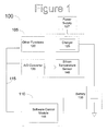
- FIG. 1 is a block diagram of a portable device circuit incorporating principles of the present invention.
- FIG. 2 is a flow chart of a method for charging a battery in a portable device incorporating principles of the present invention.
- Portable devices such as cellular telephones and personal digital assistants (PDAs) have become more popular in the past few years. Many of these portable devices now come with an integrated rechargeable battery, eliminating the need for buying replacement batteries. However, as portable devices have become more powerful, so too have their batteries. These more powerful batteries require more power to charge, which can cause the charging circuitry to radiate thermal heat throughout the portable device. This heat can cause the internal circuitry of the portable device, for example a cellular telephone, to become damaged or cause performance degradation of any thermally sensitive components in the cellular telephone.
- the present invention utilizes a software controlled thermal temperature control to maintain a safe temperature during battery charging.
- FIG. 1 illustrates a portable device circuit 100 for use in a cellular telephone.
- the analog base band circuit (ABB) 105 is operably connected to the digital base band circuit (DBB) 110 through serial interface 115 .
- Serial interface 115 is a standard serial interface, used to transfer standard control commands in the power management system, as well as charging control commands in the present invention.
- ABB 105 Integrated on ABB 105 are many hardware modules built to perform various functions. Grouped together is block 120 , which contains all other functions not vital to the charging circuitry (e.g., keypad LED controls, LCD screen controls, speaker and microphone controls). Also integrated on the ABB is charger 125 . Charger 125 has a discrete set of selectable charging currents that can be selected based upon battery capacity, desired charging rate, and safety considerations (e.g., thermal temperature being produced). An exemplary range of charging current settings would span 50 mA to 1000 mA with anywhere between 8 to 16 total discrete selections in this range. Once set to a desired charging rate, charger 125 controls the power output to rechargeable battery 130 . Also operably connected to charger 125 is power supply 127 .
- power supply 127 Also operably connected to charger 125 .
- Analog/Digital (ND) converter 135 is operably connected to a silicon temperature sensor 140 .
- Sensor 140 is used to monitor the temperature of the silicon components onboard ABB 105 during charging. As battery 130 is charged, charger 125 emits thermal heat, which if unregulated will result in damage to circuit components. Sensor 140 outputs a voltage signal that is converted at the ND converter 135 into a digital value. This digital value is passed via serial interface 115 to DBB 110 , where software control module 145 , which is integrated into a standard cellular telephone microcontroller, will process the thermal temperature data and monitor the temperature of the charging circuitry. It should be clear to persons familiar with the related arts that the software control module can be any circuitry programmed to perform the processes, procedures and/or steps described herein.
- control module 145 send instructions to ABB 105 to lower selected power levels, for example, by instructing the charger 125 to reduce the amount of power being sent to the battery until a safe temperature is reached or by instructing the charger to turn off and on with a duty cycle that decreases the average power dissipation to a level that meets a desired temperature level on the ABB.
- the software control loop can change the power dissipation of other elements in the system, typically on the ABB, allowing the battery charging current to be maintained and minimizing/optimizing the total charging time while controlling heat in the ABB and the whole system.
- the thermal sensor is shown in FIG. 1 , this is shown by way of example only, and is not meant to limit the present invention. Multiple sensors can be embedded in multiple regions of the ABB to allow localized thermal temperature control.
- the A/D converter can be used to monitor each of the thermal sensor values and convert them to digital values for use by the charging control module. The full functionality of the system is explained below with respect to FIG. 2 .
- FIG. 2 is a flow chart illustrating a method for charging a battery utilizing the circuit discussed in FIG. 1 , while utilizing principles of the present invention to alter the power levels of charger 125 to maintain a safe thermal temperature on the ABB 105 circuit.
- the battery charging is initiated in step 200 .
- control module 145 instructs the silicon temperature sensor 140 to check the temperature of the circuitry in step 205 .
- A/D converter 135 converts the voltage output of sensor 140 to a digital signal, and returns the digital signal to control module 145 .
- control module 145 receives the converted digital temperature signal, the process continues to step 210 where the control module must determine if the temperature of the ABB is within an accepted range.
- an accepted temperature range for the ABB is 110-115° C. If the temperature of the ABB falls within the accepted temperature range, the process returns back to step 205 where the temperature is again checked. However, if the temperature falls outside of the accepted temperature range, the process continues to step 215 .
- the microcontroller instructs various components on the ABB to lower their power levels. In one instance, the microcontroller instructs the battery charger to lower the charging power being used. If the temperature exceeds the maximum ABB operating temperature range, the software selects a lower battery charging power or a lower on/off duty cycle and reprograms the battery charger. Conversely, if the ABB temperature is below the minimum charging temperature trip point (i.e., below the maximum ABB operating temperature range discussed above), the software increases the charging power being provided to the battery, and reprograms the battery charger to operate at the new settings.
- the minimum charging temperature trip point i.e., below the maximum ABB operating temperature range discussed above
- step 220 the microcontroller waits a small period of time, for example approximately 500 milliseconds, for the changes to the programming of the charger. Once the wait time is elapsed, the process continues back to step 205 where the ABB temperature is once again checked. This process continues until the battery is fully charged, or until a power supply to the charging circuit is disconnected.
Abstract
Description
Claims (28)
Priority Applications (1)
| Application Number | Priority Date | Filing Date | Title |
|---|---|---|---|
| US12/766,133 US7944180B2 (en) | 2006-08-29 | 2010-04-23 | Software based thermal charging regulation loop |
Applications Claiming Priority (2)
| Application Number | Priority Date | Filing Date | Title |
|---|---|---|---|
| US11/511,607 US7733064B2 (en) | 2006-08-29 | 2006-08-29 | Software based thermal charging regulation loop |
| US12/766,133 US7944180B2 (en) | 2006-08-29 | 2010-04-23 | Software based thermal charging regulation loop |
Related Parent Applications (1)
| Application Number | Title | Priority Date | Filing Date |
|---|---|---|---|
| US11/511,607 Continuation US7733064B2 (en) | 2006-08-29 | 2006-08-29 | Software based thermal charging regulation loop |
Publications (2)
| Publication Number | Publication Date |
|---|---|
| US20100203928A1 US20100203928A1 (en) | 2010-08-12 |
| US7944180B2 true US7944180B2 (en) | 2011-05-17 |
Family
ID=39150546
Family Applications (2)
| Application Number | Title | Priority Date | Filing Date |
|---|---|---|---|
| US11/511,607 Active 2028-02-29 US7733064B2 (en) | 2006-08-29 | 2006-08-29 | Software based thermal charging regulation loop |
| US12/766,133 Expired - Fee Related US7944180B2 (en) | 2006-08-29 | 2010-04-23 | Software based thermal charging regulation loop |
Family Applications Before (1)
| Application Number | Title | Priority Date | Filing Date |
|---|---|---|---|
| US11/511,607 Active 2028-02-29 US7733064B2 (en) | 2006-08-29 | 2006-08-29 | Software based thermal charging regulation loop |
Country Status (1)
| Country | Link |
|---|---|
| US (2) | US7733064B2 (en) |
Families Citing this family (8)
| Publication number | Priority date | Publication date | Assignee | Title |
|---|---|---|---|---|
| GB2459092B (en) * | 2008-04-07 | 2010-07-07 | Twinhead Int Corp | Portable electronic device and method of adjusting charging current for a rechargeable batttery unit thereof |
| JP5694874B2 (en) * | 2011-07-21 | 2015-04-01 | 京セラ株式会社 | Communication terminal, charge control program, and charge control method |
| CN108631399A (en) * | 2012-11-21 | 2018-10-09 | 长泰品原电子科技有限公司 | Battery protecting apparatus and its method |
| US11005283B2 (en) | 2015-01-14 | 2021-05-11 | Black & Decker Inc. | Battery charger and method of charging a battery |
| KR102629141B1 (en) | 2016-04-25 | 2024-01-26 | 삼성전자주식회사 | Method for controlling chargering of battery and electronic device thereof |
| CN110014930A (en) * | 2017-12-14 | 2019-07-16 | 郑州宇通客车股份有限公司 | A kind of charging connection guard method and device |
| CN108365871B (en) * | 2018-02-23 | 2022-07-08 | 南京飞腾电子科技有限公司 | Carrier communication circuit based on OFDM mode modulation and power supply method thereof |
| CN112558740B (en) * | 2019-09-26 | 2024-02-13 | 戴尔产品有限公司 | Charging system for spare equipment of component throttling power |
Citations (12)
| Publication number | Priority date | Publication date | Assignee | Title |
|---|---|---|---|---|
| US5339018A (en) | 1989-06-30 | 1994-08-16 | Analog Devices, Inc. | Integrated circuit monitor for storage battery voltage and temperature |
| US5483145A (en) | 1991-07-25 | 1996-01-09 | Toshiba Battery Co., Ltd. | Secondary battery charging circuit |
| US5912547A (en) | 1994-09-13 | 1999-06-15 | Intermec Ip Corp. | Battery charging method and apparatus with thermal mass equalization |
| US5918186A (en) | 1996-10-15 | 1999-06-29 | Ericsson Inc. | Rechargeable battery enabling reduction of battery overheating probability during charging |
| US5965998A (en) | 1996-07-02 | 1999-10-12 | Century Mfg. Co. | Automatic polarity and condition sensing battery charger |
| US6100664A (en) | 1999-03-31 | 2000-08-08 | Motorola Inc. | Sub-miniature high efficiency battery charger exploiting leakage inductance of wall transformer power supply, and method therefor |
| US6373228B1 (en) | 1999-11-10 | 2002-04-16 | Makita Corporation | Battery charging device |
| US20040135551A1 (en) | 2001-04-19 | 2004-07-15 | Hoff C. Michael | Method and system for charging a NiMH or NiCd battery |
| US20060139009A1 (en) | 2004-12-23 | 2006-06-29 | So John S K | Digital temperature compensation for battery charging circuits |
| US20070126405A1 (en) | 2005-12-02 | 2007-06-07 | Wei-Peng Kao | Battery charging system and related method for preventing overheating while charging |
| US7453239B2 (en) * | 2003-10-29 | 2008-11-18 | Makita Corporation | Charging apparatus having a switching element for controlling charging power |
| US7598710B2 (en) * | 2006-12-08 | 2009-10-06 | Monolithic Power Systems, Inc. | Battery charger with temperature control |
-
2006
- 2006-08-29 US US11/511,607 patent/US7733064B2/en active Active
-
2010
- 2010-04-23 US US12/766,133 patent/US7944180B2/en not_active Expired - Fee Related
Patent Citations (12)
| Publication number | Priority date | Publication date | Assignee | Title |
|---|---|---|---|---|
| US5339018A (en) | 1989-06-30 | 1994-08-16 | Analog Devices, Inc. | Integrated circuit monitor for storage battery voltage and temperature |
| US5483145A (en) | 1991-07-25 | 1996-01-09 | Toshiba Battery Co., Ltd. | Secondary battery charging circuit |
| US5912547A (en) | 1994-09-13 | 1999-06-15 | Intermec Ip Corp. | Battery charging method and apparatus with thermal mass equalization |
| US5965998A (en) | 1996-07-02 | 1999-10-12 | Century Mfg. Co. | Automatic polarity and condition sensing battery charger |
| US5918186A (en) | 1996-10-15 | 1999-06-29 | Ericsson Inc. | Rechargeable battery enabling reduction of battery overheating probability during charging |
| US6100664A (en) | 1999-03-31 | 2000-08-08 | Motorola Inc. | Sub-miniature high efficiency battery charger exploiting leakage inductance of wall transformer power supply, and method therefor |
| US6373228B1 (en) | 1999-11-10 | 2002-04-16 | Makita Corporation | Battery charging device |
| US20040135551A1 (en) | 2001-04-19 | 2004-07-15 | Hoff C. Michael | Method and system for charging a NiMH or NiCd battery |
| US7453239B2 (en) * | 2003-10-29 | 2008-11-18 | Makita Corporation | Charging apparatus having a switching element for controlling charging power |
| US20060139009A1 (en) | 2004-12-23 | 2006-06-29 | So John S K | Digital temperature compensation for battery charging circuits |
| US20070126405A1 (en) | 2005-12-02 | 2007-06-07 | Wei-Peng Kao | Battery charging system and related method for preventing overheating while charging |
| US7598710B2 (en) * | 2006-12-08 | 2009-10-06 | Monolithic Power Systems, Inc. | Battery charger with temperature control |
Non-Patent Citations (3)
| Title |
|---|
| Final Office Action dated Nov. 24, 2009 for U.S. Appl. No. 11/511,607, filed Aug. 29, 2006. |
| Non-Final Office Action dated Dec. 12, 2008 for U.S. Appl. No. 11/511,607, filed Aug. 29, 2006. |
| Notice of Allowance dated Feb. 17, 2010 for U.S. Appl. No. 11/511,607, filed Aug. 29, 2006. |
Also Published As
| Publication number | Publication date |
|---|---|
| US20080054853A1 (en) | 2008-03-06 |
| US7733064B2 (en) | 2010-06-08 |
| US20100203928A1 (en) | 2010-08-12 |
Similar Documents
| Publication | Publication Date | Title |
|---|---|---|
| US7944180B2 (en) | Software based thermal charging regulation loop | |
| US10432008B2 (en) | Systems and methods for charging a battery | |
| JP3638658B2 (en) | Battery recharging device and battery recharging method | |
| CN101237153B (en) | Battery charging circuit and method for charging battery | |
| US8773077B1 (en) | Controllers for battery chargers and battery chargers therefrom | |
| TWI389421B (en) | Electronic system and method for managing power thereof | |
| US7808127B2 (en) | Multile input channel power control circuit | |
| JP7154020B2 (en) | System and method for controlling battery current | |
| US8884589B2 (en) | Method and system for power switch temperature regulation | |
| JP2010178591A (en) | Charging circuit, charging device, electronic apparatus, and charging method | |
| JP5884414B2 (en) | Control system | |
| US20090121644A1 (en) | Adaptive algorithm for camera flash led power control vs. battery impedance, state of discharge (sod), aging, temperature effects | |
| CN103227488B (en) | Method for controlling charging voltage of mobile terminal and charging conversion device | |
| US20150288187A1 (en) | Energy management system for controlling energy to a load powered by a thermoelectric module | |
| US20110227525A1 (en) | Charging Circuit, Method, and System | |
| WO2017128619A1 (en) | Device, apparatus, and method supporting multi-battery quick-charging | |
| KR20150053226A (en) | Virtual Cell for Battery Thermal Management | |
| RU2403656C1 (en) | Method of using lithium-ion accumulator battery in artificial earth satellite | |
| US6850040B2 (en) | Charge boost battery charging and protection circuit | |
| TWI633739B (en) | Battery charging system with a regulation loop and charging method | |
| CN107317388B (en) | Method for controlling UPS input current and UPS controller | |
| KR101904986B1 (en) | Wireless sensor node with power management function | |
| US8217530B2 (en) | System for managing power based on current monitoring | |
| JP2008061488A (en) | Power supply system equipped with remote control circuit, and method for operating the power supply system | |
| US6700807B1 (en) | Flexible converter |
Legal Events
| Date | Code | Title | Description |
|---|---|---|---|
| AS | Assignment |
Owner name: AGERE SYSTEMS INC., PENNSYLVANIA Free format text: ASSIGNMENT OF ASSIGNORS INTEREST;ASSIGNOR:LOPATA, DOUGLAS D.;REEL/FRAME:024371/0170 Effective date: 20080510 |
|
| STCF | Information on status: patent grant |
Free format text: PATENTED CASE |
|
| AS | Assignment |
Owner name: DEUTSCHE BANK AG NEW YORK BRANCH, AS COLLATERAL AG Free format text: PATENT SECURITY AGREEMENT;ASSIGNORS:LSI CORPORATION;AGERE SYSTEMS LLC;REEL/FRAME:032856/0031 Effective date: 20140506 |
|
| FPAY | Fee payment |
Year of fee payment: 4 |
|
| AS | Assignment |
Owner name: AVAGO TECHNOLOGIES GENERAL IP (SINGAPORE) PTE. LTD Free format text: ASSIGNMENT OF ASSIGNORS INTEREST;ASSIGNOR:AGERE SYSTEMS LLC;REEL/FRAME:035365/0634 Effective date: 20140804 |
|
| AS | Assignment |
Owner name: AGERE SYSTEMS LLC, PENNSYLVANIA Free format text: TERMINATION AND RELEASE OF SECURITY INTEREST IN PATENT RIGHTS (RELEASES RF 032856-0031);ASSIGNOR:DEUTSCHE BANK AG NEW YORK BRANCH, AS COLLATERAL AGENT;REEL/FRAME:037684/0039 Effective date: 20160201 Owner name: LSI CORPORATION, CALIFORNIA Free format text: TERMINATION AND RELEASE OF SECURITY INTEREST IN PATENT RIGHTS (RELEASES RF 032856-0031);ASSIGNOR:DEUTSCHE BANK AG NEW YORK BRANCH, AS COLLATERAL AGENT;REEL/FRAME:037684/0039 Effective date: 20160201 |
|
| AS | Assignment |
Owner name: BANK OF AMERICA, N.A., AS COLLATERAL AGENT, NORTH CAROLINA Free format text: PATENT SECURITY AGREEMENT;ASSIGNOR:AVAGO TECHNOLOGIES GENERAL IP (SINGAPORE) PTE. LTD.;REEL/FRAME:037808/0001 Effective date: 20160201 Owner name: BANK OF AMERICA, N.A., AS COLLATERAL AGENT, NORTH Free format text: PATENT SECURITY AGREEMENT;ASSIGNOR:AVAGO TECHNOLOGIES GENERAL IP (SINGAPORE) PTE. LTD.;REEL/FRAME:037808/0001 Effective date: 20160201 |
|
| AS | Assignment |
Owner name: AVAGO TECHNOLOGIES GENERAL IP (SINGAPORE) PTE. LTD., SINGAPORE Free format text: TERMINATION AND RELEASE OF SECURITY INTEREST IN PATENTS;ASSIGNOR:BANK OF AMERICA, N.A., AS COLLATERAL AGENT;REEL/FRAME:041710/0001 Effective date: 20170119 Owner name: AVAGO TECHNOLOGIES GENERAL IP (SINGAPORE) PTE. LTD Free format text: TERMINATION AND RELEASE OF SECURITY INTEREST IN PATENTS;ASSIGNOR:BANK OF AMERICA, N.A., AS COLLATERAL AGENT;REEL/FRAME:041710/0001 Effective date: 20170119 |
|
| AS | Assignment |
Owner name: AVAGO TECHNOLOGIES INTERNATIONAL SALES PTE. LIMITE Free format text: MERGER;ASSIGNOR:AVAGO TECHNOLOGIES GENERAL IP (SINGAPORE) PTE. LTD.;REEL/FRAME:047642/0417 Effective date: 20180509 |
|
| FEPP | Fee payment procedure |
Free format text: MAINTENANCE FEE REMINDER MAILED (ORIGINAL EVENT CODE: REM.); ENTITY STATUS OF PATENT OWNER: LARGE ENTITY |
|
| AS | Assignment |
Owner name: AVAGO TECHNOLOGIES INTERNATIONAL SALES PTE. LIMITE Free format text: CORRECTIVE ASSIGNMENT TO CORRECT THE EXECUTION DATE OF THE MERGER PREVIOUSLY RECORDED ON REEL 047642 FRAME 0417. ASSIGNOR(S) HEREBY CONFIRMS THE ASSIGNMENT,;ASSIGNOR:AVAGO TECHNOLOGIES GENERAL IP (SINGAPORE) PTE. LTD.;REEL/FRAME:048521/0395 Effective date: 20180905 |
|
| LAPS | Lapse for failure to pay maintenance fees |
Free format text: PATENT EXPIRED FOR FAILURE TO PAY MAINTENANCE FEES (ORIGINAL EVENT CODE: EXP.); ENTITY STATUS OF PATENT OWNER: LARGE ENTITY |
|
| STCH | Information on status: patent discontinuation |
Free format text: PATENT EXPIRED DUE TO NONPAYMENT OF MAINTENANCE FEES UNDER 37 CFR 1.362 |
|
| FP | Lapsed due to failure to pay maintenance fee |
Effective date: 20190517 |