US7944633B2 - Lens holder for alignment of stacked lens module and manufacturing method thereof - Google Patents
Lens holder for alignment of stacked lens module and manufacturing method thereof Download PDFInfo
- Publication number
- US7944633B2 US7944633B2 US12/557,251 US55725109A US7944633B2 US 7944633 B2 US7944633 B2 US 7944633B2 US 55725109 A US55725109 A US 55725109A US 7944633 B2 US7944633 B2 US 7944633B2
- Authority
- US
- United States
- Prior art keywords
- alignment
- lens
- stacked
- mold
- submodule
- Prior art date
- Legal status (The legal status is an assumption and is not a legal conclusion. Google has not performed a legal analysis and makes no representation as to the accuracy of the status listed.)
- Expired - Fee Related
Links
- 238000004519 manufacturing process Methods 0.000 title abstract description 21
- 238000000465 moulding Methods 0.000 claims abstract description 55
- 238000002347 injection Methods 0.000 claims abstract description 14
- 239000007924 injection Substances 0.000 claims abstract description 14
- 230000003287 optical effect Effects 0.000 claims description 77
- 238000001746 injection moulding Methods 0.000 claims description 17
- 239000011521 glass Substances 0.000 claims description 10
- 125000006850 spacer group Chemical group 0.000 claims description 5
- 239000006059 cover glass Substances 0.000 claims description 2
- 238000000034 method Methods 0.000 abstract description 16
- 238000001723 curing Methods 0.000 description 11
- 239000003292 glue Substances 0.000 description 10
- 239000000463 material Substances 0.000 description 10
- 238000001816 cooling Methods 0.000 description 5
- 239000005304 optical glass Substances 0.000 description 4
- 238000003848 UV Light-Curing Methods 0.000 description 3
- 238000010438 heat treatment Methods 0.000 description 3
- 238000003825 pressing Methods 0.000 description 3
- 239000000853 adhesive Substances 0.000 description 2
- 230000001070 adhesive effect Effects 0.000 description 2
- 239000002184 metal Substances 0.000 description 2
- 238000012986 modification Methods 0.000 description 2
- 230000004048 modification Effects 0.000 description 2
- 229920001187 thermosetting polymer Polymers 0.000 description 2
- 101001093143 Homo sapiens Protein transport protein Sec61 subunit gamma Proteins 0.000 description 1
- 101000694017 Homo sapiens Sodium channel protein type 5 subunit alpha Proteins 0.000 description 1
- 101100120905 Saccharomyces cerevisiae (strain ATCC 204508 / S288c) TDH1 gene Proteins 0.000 description 1
- 102100027198 Sodium channel protein type 5 subunit alpha Human genes 0.000 description 1
- 238000004026 adhesive bonding Methods 0.000 description 1
- 238000006243 chemical reaction Methods 0.000 description 1
- 230000000694 effects Effects 0.000 description 1
- 239000005357 flat glass Substances 0.000 description 1
- 238000003384 imaging method Methods 0.000 description 1
- 239000000155 melt Substances 0.000 description 1
- 230000005499 meniscus Effects 0.000 description 1
- 239000012778 molding material Substances 0.000 description 1
Images


Classifications
-
- B—PERFORMING OPERATIONS; TRANSPORTING
- B29—WORKING OF PLASTICS; WORKING OF SUBSTANCES IN A PLASTIC STATE IN GENERAL
- B29C—SHAPING OR JOINING OF PLASTICS; SHAPING OF MATERIAL IN A PLASTIC STATE, NOT OTHERWISE PROVIDED FOR; AFTER-TREATMENT OF THE SHAPED PRODUCTS, e.g. REPAIRING
- B29C45/00—Injection moulding, i.e. forcing the required volume of moulding material through a nozzle into a closed mould; Apparatus therefor
- B29C45/14—Injection moulding, i.e. forcing the required volume of moulding material through a nozzle into a closed mould; Apparatus therefor incorporating preformed parts or layers, e.g. injection moulding around inserts or for coating articles
- B29C45/14065—Positioning or centering articles in the mould
-
- B—PERFORMING OPERATIONS; TRANSPORTING
- B29—WORKING OF PLASTICS; WORKING OF SUBSTANCES IN A PLASTIC STATE IN GENERAL
- B29C—SHAPING OR JOINING OF PLASTICS; SHAPING OF MATERIAL IN A PLASTIC STATE, NOT OTHERWISE PROVIDED FOR; AFTER-TREATMENT OF THE SHAPED PRODUCTS, e.g. REPAIRING
- B29C43/00—Compression moulding, i.e. applying external pressure to flow the moulding material; Apparatus therefor
- B29C43/02—Compression moulding, i.e. applying external pressure to flow the moulding material; Apparatus therefor of articles of definite length, i.e. discrete articles
- B29C43/18—Compression moulding, i.e. applying external pressure to flow the moulding material; Apparatus therefor of articles of definite length, i.e. discrete articles incorporating preformed parts or layers, e.g. compression moulding around inserts or for coating articles
-
- G—PHYSICS
- G02—OPTICS
- G02B—OPTICAL ELEMENTS, SYSTEMS OR APPARATUS
- G02B7/00—Mountings, adjusting means, or light-tight connections, for optical elements
- G02B7/02—Mountings, adjusting means, or light-tight connections, for optical elements for lenses
- G02B7/021—Mountings, adjusting means, or light-tight connections, for optical elements for lenses for more than one lens
-
- B—PERFORMING OPERATIONS; TRANSPORTING
- B29—WORKING OF PLASTICS; WORKING OF SUBSTANCES IN A PLASTIC STATE IN GENERAL
- B29C—SHAPING OR JOINING OF PLASTICS; SHAPING OF MATERIAL IN A PLASTIC STATE, NOT OTHERWISE PROVIDED FOR; AFTER-TREATMENT OF THE SHAPED PRODUCTS, e.g. REPAIRING
- B29C45/00—Injection moulding, i.e. forcing the required volume of moulding material through a nozzle into a closed mould; Apparatus therefor
- B29C45/14—Injection moulding, i.e. forcing the required volume of moulding material through a nozzle into a closed mould; Apparatus therefor incorporating preformed parts or layers, e.g. injection moulding around inserts or for coating articles
- B29C45/14065—Positioning or centering articles in the mould
- B29C2045/14131—Positioning or centering articles in the mould using positioning or centering means forming part of the insert
-
- B—PERFORMING OPERATIONS; TRANSPORTING
- B29—WORKING OF PLASTICS; WORKING OF SUBSTANCES IN A PLASTIC STATE IN GENERAL
- B29K—INDEXING SCHEME ASSOCIATED WITH SUBCLASSES B29B, B29C OR B29D, RELATING TO MOULDING MATERIALS OR TO MATERIALS FOR MOULDS, REINFORCEMENTS, FILLERS OR PREFORMED PARTS, e.g. INSERTS
- B29K2709/00—Use of inorganic materials not provided for in groups B29K2703/00 - B29K2707/00, for preformed parts, e.g. for inserts
- B29K2709/08—Glass
-
- B—PERFORMING OPERATIONS; TRANSPORTING
- B29—WORKING OF PLASTICS; WORKING OF SUBSTANCES IN A PLASTIC STATE IN GENERAL
- B29L—INDEXING SCHEME ASSOCIATED WITH SUBCLASS B29C, RELATING TO PARTICULAR ARTICLES
- B29L2011/00—Optical elements, e.g. lenses, prisms
-
- B—PERFORMING OPERATIONS; TRANSPORTING
- B29—WORKING OF PLASTICS; WORKING OF SUBSTANCES IN A PLASTIC STATE IN GENERAL
- B29L—INDEXING SCHEME ASSOCIATED WITH SUBCLASS B29C, RELATING TO PARTICULAR ARTICLES
- B29L2011/00—Optical elements, e.g. lenses, prisms
- B29L2011/0016—Lenses
Definitions
- the present invention relates to a lens holder for alignment of a stacked lens module and a manufacturing method thereof, especially to a lens module with a lens holder for alignment formed by injection or press molding of an embedded molding insert that is a stacked lens submodule.
- This kind of lens module is especially suitable for camera lenses, small lenses, and mobile phone lenses.
- the optical lens is a compact optical element in cameras or lenses of camera phones.
- the optical element is formed by at least one optical lens.
- an optical lens 20 a is made from optical plastic or optical glass and having an optical surface 21 a that generally is a round surface, and an outer periphery 22 a around the optical surface 21 a that can be round or rectangular.
- the lens 20 a is glued and fixed in a holding ring (or holder) 10 a to form an optical lens set (or assembly) 1 a while the holding ring 10 a is made from metal or plastic.
- the lens 20 a is aligned with a central axis (optical axis) of the lens module.
- the holding ring 10 a moves inside the lens module so as to achieve zoom in/zoom out, as shown in U.S. Pat. Nos. 7,312,933, 7,095,572, US2007/0024989 and JP3650594.
- FIG. 1 A conventional way of fixing the plastic or glass lens 20 a in the holding ring 10 a is shown in FIG. 1 , especially suitable for glass lens.
- a holding ring 10 a according to shape of the outer periphery 22 a of the lens 20 a such as round or rectangular shape.
- the lens 20 a is set into a preset hole of holding ring 10 a for being located.
- glue is UV glue that requires a curing process such as being radiated in a UV curing oven for curing. Due to compact size of the lens 20 a , the optical surface 21 a is easy to get scratched or attach with the glue (flow) when the lens 20 a is located and fixed by automatic or manual gluing.
- a technique that places a molding insert in a mold cavity and then treated with injection molding is called a molding insert injection molding method.
- a molding insert for example, metal part
- a molding insert is set into a mold cavity of a preset mold.
- inject melt plastic (or rubber) material to fill a preset molding area (material injecting area) and cover whole or part of the molding insert.
- the product is released from the mold.
- Such manufacturing method is applied broadly to electric elements, connector, mechanical parts and LED, as disclosed in U.S. Pat. No. 5,923,805, TWM313317, and JP07-120610 etc. While manufacturing a cover with plastic lens by such method, the cover (a housing) is used as a molding insert and put into a mold cavity.
- a plastic lens is made by plastic injection and is integrated with the cover.
- the plastic lens is used as a molding insert and the cover is made by plastic injection and integrated with the plastic lens so as to form an integrated cover with plastic lens, as shown in TW 0528279 and U.S. Pat. No. 6,825,503.
- the glass plate is used as an molding insert and is covered by plastic material so as to form a window glass or other parts.
- U.S. Pat. No. 6,710,945 by two injection holes for plastic material, a molded lens and a lens holder are molded by injection sequentially. Or use infrared gas as the molding insert and produce a mount covering the glass by injection molding.
- the eyeglass frame is used as an molding insert and is placed into a mold cavity.
- the preform of the plastic lens is heated to a melt status and then the soft preform is turned into the shape of the cavity by heating and pressing of the mold
- the press molding technique is unable to be applied to a manufacturing process that integrated the glass lens with the plastic holding ring.
- the softening point of the optical glass is about 500° C. that is far more higher than the deformation temperature such as 80° C. of the plastic holding ring.
- the plastic holding ring has already deformed and unable to be molded. Therefore, the press molding is unable to be applied to mass production of the product that uses a plastic holding ring as an molding insert and glass as molding material.
- an optical lens an alignment fixture and a sensor are mounted into a mold and then inject plastic to form a lens module.
- FIG. 2 as shown in TWM337077, two optical glass lenses 20 b , two light shields 30 b , a spacer 40 b are used as molding inserts to be mounted into molds 31 b , 32 b in turn.
- a lens holder together with the above molding inserts being covered form a lens module by plastic injection molding or press molding.
- such technique is unable to be used in the stacked lens submodule already being assembled.
- the stacked lens submodule is an integrated part and is unable to be separated into each single element to be set into a mold. Moreover, the optical axes of the optical lenses 20 b , 30 b , 40 b are difficult to be aligned with one another. It takes time and efforts for alignment of the optical axis and this leads to low production rate and poor precision.
- the lens holder outside a stacked lens submodule needs high precision.
- the location precision between the stacked lens submodule and the lens holder has great effects on imaging of the lens.
- how the stacked lens submodule and the lend holder are aligned with an optical axis affects resolution of the images. Therefore, there is a need to develop a new technique applied to assembling of the stacked lens submodule with the lens holder and mass-produce lens modules with good alignment precision by simplified manufacturing processes.
- a stacked lens submodule is used as a molding insert put into a mold cavity.
- an integrated module having a stacked lens submodule and a lens holder is formed and is applied to assembled lenses of LED light sources/Solar Conversion Systems or optical lenses of cameras/mobile phone cameras.
- the stacked lens submodule includes at least one optical lens and optical element stacked and assembled by glue.
- the optical element include one of the followings or their combinations: an optical lens, a spacer, an aperture, a cover glass, an infrared(IR)-cut glass, an image sensor, and so on.
- the glue can be thermoset adhesive or ultraviolet curing adhesive.
- the lens holder for alignment of stacked lens modules features on that: the stacked lens submodule is disposed with at least one first alignment fixture that is concentric with optical axis.
- the first alignment fixture can be an alignment bump or an alignment groove.
- the second alignment fixture can be an alignment bump or an alignment groove corresponding to the first alignment fixture.
- An injection molding method of a lens holder for alignment according to the present invention includes following steps:
- the lens holder of the present invention can also be produced by a press molding method having steps from SS1 to SS5.
- the lens holder for alignment further includes a third alignment fixture such as alignment groove that is formed by demolding of a fourth alignment fixture (such as alignment pin) on the mold (such as the upper mold).
- a third alignment fixture such as alignment groove that is formed by demolding of a fourth alignment fixture (such as alignment pin) on the mold (such as the upper mold).
- FIG. 1 is a schematic drawing showing a prior art
- FIG. 2 is a schematic drawing showing another prior art
- FIG. 3 is a cross sectional view of an embodiment applied to a rectangular stacked lens module of camera lenses according to the present invention
- FIG. 4 is a bottom view of the embodiment in FIG. 3 ;
- FIG. 5 is a top view of a lens holder for alignment of the embodiment in FIG. 3 ;
- FIG. 6 is a bottom view of the lens holder for alignment including a stacked lens submodule but without IR-cut filter of the embodiment in FIG. 3 ;
- FIG. 7 shows assembling of the lens holder for alignment of the embodiment in FIG. 3 ;
- FIG. 8 shows an upper mold of the lens holder for alignment of the embodiment in FIG. 3 ;
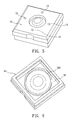
- FIG. 9 is a perspective view of an embodiment applied to a round stacked lens module of camera lenses according to the present invention.
- FIG. 10 is a top view of the embodiment in FIG. 9 ;
- FIG. 11 is a cross sectional view of the embodiment in FIG. 9 along a line A-A′;
- FIG. 12 is another cross sectional view of the embodiment in FIG. 9 along a line B-B′;
- FIG. 13 is a side view of the embodiment in FIG. 9 ;
- FIG. 14 shows a lower mold with at least one alignment groove of the embodiment in FIG. 9 ;
- FIG. 15 shows assembling of an alignment bump of a stacked lens submodule with an alignment groove of the lower mold of the embodiment in FIG. 9 ;
- FIG. 16 is a cross sectional view of a further embodiment applied to a round stacked lens module according to the present invention.
- a lens holder for alignment of a rectangular stacked lens module of camera lenses and a manufacturing method thereof The rectangular stacked lens module 1 is produced by a rectangular stacked lens submodule 20 used as a molding insert.
- the molding insert is put into a cavity of a mold 3 , as shown in FIG. 7 .
- a lens module 1 integrated with the stacked lens submodule 20 and having a rectangular lens holder for alignment 10 is formed.
- the stacked lens submodule 20 includes at least one rectangular optical lens 21 and related optical elements stacked and glued with one another.
- the glue can be thermoset glue or ultraviolet (UV) curing glue.
- the stacked lens submodule 20 in this embodiment consists of two optical lenses 21 a , 21 b , and a front-positioned aperture 22 .
- the stacked lens submodule 20 further includes a spacer 23 , as shown in FIG. 11 , FIG. 12 , an IR-cut glass 24 and an image sensor (not shown in figure).
- the rectangular lens holder for alignment 10 of this embodiment features on that: the second optical lens 21 b of the stacked lens submodule 20 is disposed with a first alignment fixture 202 that is concentric with an optical axis of the lens and is a circular alignment bump 202 . While manufacturing the second optical lens 21 b , the mold of the lens is with a concentric circular groove whose center is on the optical axis of the lens optical surface so that the second optical lens 21 b and the first alignment fixture 202 are produced integratedly. By the connection of the alignment bump 202 with the corresponding second alignment fixture 36 of the mold 3 , the stacked lens submodule 20 is aligned and fixed.
- the optical axis of the stacked lens submodule 20 is aligned with the central axis of the molded lens holder for alignment 10 .
- the second alignment fixture 36 of the mold 3 is an alignment groove 36 corresponding to the first alignment fixture (alignment bump) 202 .
- an injection molding method of a rectangular lens holder for alignment 10 in this embodiment according to the present invention includes following steps:
- the rectangular lens holder for alignment 10 of this embodiment can also be produced by press molding.
- the manufacturing method of the press molding and related steps are similar to those of the injection molding while the main difference between them is in the step S4: put plastic with preset weight (usually, a perform is used) into a cavity formed by the lower mold 31 and the upper mold 32 so as to perform press molding.
- the rectangular lens holder for alignment 10 can further include a third alignment fixture 12 such as an alignment cavity, corresponding to a fourth alignment fixture 35 such as an alignment pin disposed on the upper mold 32 .
- the fourth alignment fixture 35 of the upper mold 32 can be a plurality of alignments pins with the same length and arranged symmetrically and circularly such as four pins(only two are shown in FIG. 8 ).
- the fourth alignment fixture (four pins) 35 is aligned and pressed evenly on an upper surface 201 of non-optical area of the stacked lens submodule 20 .
- the optical axis of the stacked lens submodule 20 will not be oblique during injection or press molding processes and aligned with the optical axis of the molded lens holder for alignment 10 .
- the third alignment fixture 12 such as four alignment cavities is formed on the molded rectangular lens holder for alignment 10 .
- the injection molding method of this a rectangular lens holder for alignment rectangular lens holder for alignment 10 includes the steps similar to those of the injection molding method mentioned above. The difference between them is in that: the step S3 further includes a step of pressing and aligning the fourth alignment fixture 35 (four alignment pins) firmly on an upper surface 201 of non-optical area of the rectangular stacked lens submodule 20 so as to make the stacked lens submodule 20 and the integrated rectangular lens holder for alignment 10 align with the optical axis precisely.
- this embodiment is a lens holder for alignment of a round stacked lens module applied to mobile phone cameras and a manufacturing method thereof.
- a round stacked lens module 1 of this embodiment uses a round stacked lens submodule 20 as a molding insert that is put into a mold cavity. By injection molding or press molding of the molded molding inset a lens module 1 having a round lens holder for alignment 10 and integrated with the round stacked lens submodule 20 is formed.
- the stacked lens submodule 20 in this embodiment includes two round optical lenses 21 a , 21 b and a spacer 23 .
- the round lens holder 10 for alignment of the round stacked lens module 1 in this embodiment features on that: the optical lens 21 b of the stacked lens submodule 20 is disposed with a first alignment fixture 202 such as an alignment bump that is concentric with the optical axis of the optical lens 21 b , as shown in FIG. 11 .
- a first alignment fixture 202 such as an alignment bump that is concentric with the optical axis of the optical lens 21 b , as shown in FIG. 11 .
- the stacked lens submodule 20 is aligned with the injection molded/or press molded round lens holder for alignment 10 and is aligned with the optical axis of the round lens holder for alignment 10 by connection of the alignment bump 202 with the alignment groove 36 .
- the injection molding method or press molding method of the round lens holder for alignment 10 consists of the steps similar to those of the embodiment one.
- the difference between the two embodiments is only in that: the shape of the mold cavity of the lower mold 31 and the upper mold 32 is changed from a rectangle to a round form.
- the round lens holder for alignment 10 in this embodiment Her includes an alignment groove 12 that is formed by demolding of the alignment fixture 35 of the upper mold 32 and the injection molding method of such lens holder for alignment 10 consists of the steps similar to those of the embodiment one. Moreover, for convenience or requirement of the assembly of the stacked lens module 1 , an integrated external thread 13 , as shown in FIG. 13 is formed on an outer surface of the round lens holder for alignment 10 .
- this embodiment is a lens holder for alignment of a round stacked lens module applied to mobile phone cameras.
- a round stacked lens module 1 of this embodiment uses a round stacked lens submodule 20 as a molding insert.
- the stacked lens submodule 20 in this embodiment includes two round optical lenses 21 a , 21 b and related optical elements stacked and glued with one another.
- the second optical lens 21 b is a meniscus whose concave surface is on the image side.
- a first alignment fixture 202 disposed thereof is a circular alignment groove with a V-shaped cross section and concentric with the optical axis.
- the lower mold 31 is arranged with a second alignment fixture 36 such as a V-shaped alignment bump 36 (not shown in figure) that is also concentric with the optical axis and corresponding to the alignment groove 202 of the stacked lens submodule 20 .
- a second alignment fixture 36 such as a V-shaped alignment bump 36 (not shown in figure) that is also concentric with the optical axis and corresponding to the alignment groove 202 of the stacked lens submodule 20 .
- the present invention has at least the following advantages:
- the stacked lens module produced by the method of the present invention can be packed in the lenses more easily, especially suitable for small cameras and mobile phone cameras. Thus the possibility of mass-production of the lens is increased.
Abstract
A lens holder for alignment of a stacked lens module and a manufacturing method thereof are revealed. A stacked lens submodule disposed with at least one first alignment fixture is used as a molding insert to be set into a mold arranged with a second alignment fixture where the first alignment fixture connects with the second alignment fixture correspondingly. Then by injection or press molding of the embedded molding insert, a lens module with the lens holder for alignment is formed. Thereby the conventional manufacturing method of the lens molder is improved, the processes are simplified and the yield rate is increased. Moreover, the molded lens module is packed into the lens more easily so that it is suitable to be applied to camera lenses, small lenses and mobile phone lenses.
Description
The present invention relates to a lens holder for alignment of a stacked lens module and a manufacturing method thereof, especially to a lens module with a lens holder for alignment formed by injection or press molding of an embedded molding insert that is a stacked lens submodule. This kind of lens module is especially suitable for camera lenses, small lenses, and mobile phone lenses.
The optical lens is a compact optical element in cameras or lenses of camera phones. In practice, the optical element is formed by at least one optical lens. Refer to FIG. 1 , an optical lens 20 a is made from optical plastic or optical glass and having an optical surface 21 a that generally is a round surface, and an outer periphery 22 a around the optical surface 21 a that can be round or rectangular. In order to fix and package the lens 20 a inside a lens module, the lens 20 a is glued and fixed in a holding ring (or holder) 10 a to form an optical lens set (or assembly) 1 a while the holding ring 10 a is made from metal or plastic. Thus the lens 20 a is aligned with a central axis (optical axis) of the lens module. Moreover, by an actuator, the holding ring 10 a (or the optical lens set 1 a) moves inside the lens module so as to achieve zoom in/zoom out, as shown in U.S. Pat. Nos. 7,312,933, 7,095,572, US2007/0024989 and JP3650594.
A conventional way of fixing the plastic or glass lens 20 a in the holding ring 10 a is shown in FIG. 1 , especially suitable for glass lens. At first, provide a holding ring 10 a according to shape of the outer periphery 22 a of the lens 20 a such as round or rectangular shape. Then the lens 20 a is set into a preset hole of holding ring 10 a for being located. Next use glue to fix the lens 20 a where the glue is UV glue that requires a curing process such as being radiated in a UV curing oven for curing. Due to compact size of the lens 20 a, the optical surface 21 a is easy to get scratched or attach with the glue (flow) when the lens 20 a is located and fixed by automatic or manual gluing. Thus the processes take time and the yield rate is poor. The curing process of the UV curing glue between the glass lens 20 a and the plastic holding ring 10 a is especially difficult. Moreover, the curing in the UV curing oven takes long time and the yield rate is poor. Thus the cost is unable to be reduced, as prior arts in JP3791615, JP06-258562, U.S. Pat. No. 7,224,542 and US 2007/0047109.
A technique that places a molding insert in a mold cavity and then treated with injection molding is called a molding insert injection molding method. A molding insert (for example, metal part) is set into a mold cavity of a preset mold. Then inject melt plastic (or rubber) material to fill a preset molding area (material injecting area) and cover whole or part of the molding insert. After cooling and curing, the product is released from the mold. Such manufacturing method is applied broadly to electric elements, connector, mechanical parts and LED, as disclosed in U.S. Pat. No. 5,923,805, TWM313317, and JP07-120610 etc. While manufacturing a cover with plastic lens by such method, the cover (a housing) is used as a molding insert and put into a mold cavity. Then a plastic lens is made by plastic injection and is integrated with the cover. Or use the plastic lens as a molding insert and the cover is made by plastic injection and integrated with the plastic lens so as to form an integrated cover with plastic lens, as shown in TW 0528279 and U.S. Pat. No. 6,825,503. Refer to JP62-251113, the glass plate is used as an molding insert and is covered by plastic material so as to form a window glass or other parts. Refer to U.S. Pat. No. 6,710,945, by two injection holes for plastic material, a molded lens and a lens holder are molded by injection sequentially. Or use infrared gas as the molding insert and produce a mount covering the glass by injection molding. Refer to U.S. Pat. No. 7,332,110, in a press molding, the eyeglass frame is used as an molding insert and is placed into a mold cavity. The preform of the plastic lens is heated to a melt status and then the soft preform is turned into the shape of the cavity by heating and pressing of the mold Thus the preform becomes a lens and integrated with the eyeglass frame to form an eyeglass. However, the press molding technique is unable to be applied to a manufacturing process that integrated the glass lens with the plastic holding ring. Once the plastic holding ring is used as a molding insert, the softening point of the optical glass is about 500° C. that is far more higher than the deformation temperature such as 80° C. of the plastic holding ring. Thus when the temperature of the mold achieves the softening point of the optical glass, the plastic holding ring has already deformed and unable to be molded. Therefore, the press molding is unable to be applied to mass production of the product that uses a plastic holding ring as an molding insert and glass as molding material.
In addition, as to manufacturing of the lens module revealed in US2009/0059398, an optical lens, an alignment fixture and a sensor are mounted into a mold and then inject plastic to form a lens module. Or as shown in FIG. 2 , as shown in TWM337077, two optical glass lenses 20 b, two light shields 30 b, a spacer 40 b are used as molding inserts to be mounted into molds 31 b, 32 b in turn. Then a lens holder together with the above molding inserts being covered form a lens module by plastic injection molding or press molding. However, such technique is unable to be used in the stacked lens submodule already being assembled. Because the stacked lens submodule is an integrated part and is unable to be separated into each single element to be set into a mold. Moreover, the optical axes of the optical lenses 20 b, 30 b, 40 b are difficult to be aligned with one another. It takes time and efforts for alignment of the optical axis and this leads to low production rate and poor precision.
Due to requirement of high precision of the optical lens set for cameras, the lens holder outside a stacked lens submodule needs high precision. The location precision between the stacked lens submodule and the lens holder has great effects on imaging of the lens. Thus how the stacked lens submodule and the lend holder are aligned with an optical axis affects resolution of the images. Therefore, there is a need to develop a new technique applied to assembling of the stacked lens submodule with the lens holder and mass-produce lens modules with good alignment precision by simplified manufacturing processes.
Therefore it is a primary object of the present invention to provide a lens holder for alignment of stacked lens modules and a manufacturing method thereof. A stacked lens submodule is used as a molding insert put into a mold cavity. By injection molding or press molding of the molding insert, an integrated module having a stacked lens submodule and a lens holder is formed and is applied to assembled lenses of LED light sources/Solar Conversion Systems or optical lenses of cameras/mobile phone cameras. The stacked lens submodule includes at least one optical lens and optical element stacked and assembled by glue. The optical element include one of the followings or their combinations: an optical lens, a spacer, an aperture, a cover glass, an infrared(IR)-cut glass, an image sensor, and so on. The glue can be thermoset adhesive or ultraviolet curing adhesive. The lens holder for alignment of stacked lens modules features on that: the stacked lens submodule is disposed with at least one first alignment fixture that is concentric with optical axis. The first alignment fixture can be an alignment bump or an alignment groove. By connection between the first alignment fixture and a corresponding second alignment fixture arranged at the mold, the stacked lens submodule is aligned. Thus the optical axis of the stacked lens submodule is aligned with a central axis of the molded lens holder for alignment. The second alignment fixture can be an alignment bump or an alignment groove corresponding to the first alignment fixture.
An injection molding method of a lens holder for alignment according to the present invention includes following steps:
- S1: providing a stacked lens submodule disposed with at least one first alignment fixture such as alignment bump or alignment groove aligned with an optical axis of the stacked lens submodule;
- S2: providing an injection mold of a lens holder having an upper mold and a lower mold while the lower mold is arranged with at least one second alignment fixture such as alignment bump or alignment groove also aligned with an optical axis of the stacked lens submodule;
- S3: putting the stacked lens submodule into the upper mold and the lower mold and the first alignment fixture of the stacked lens submodule is connected with the second alignment fixture of the lower mold for alignment and fixing of the stacked lens submodule;
- S4: heating plastic material to preset temperature and inject the plastic material through a sprue of the mold so as to form a lens holder with an alignment fixture for alignment of the stacked lens submodule;
- S5: after cooling and curing of the plastic material, separate the upper mold and the lower mold so as to release a stacked lens module with the first alignment fixture.
The lens holder of the present invention can also be produced by a press molding method having steps from SS1 to SS5.
- SS1: providing a stacked lens submodule disposed with at least one first alignment fixture such as alignment bump or alignment groove aligned with an optical axis of the stacked lens submodule;
- SS2: providing an press mold of a lens holder having an upper mold and a lower mold while the lower mold is arranged with at least one second alignment fixture such as alignment bump or alignment groove also aligned with an optical axis of the stacked lens submodule;
- SS3: putting the stacked lens submodule into the upper mold and the lower mold and the first alignment fixture of the stacked lens submodule is connected with the second alignment fixture of the lower mold for alignment and fixing of the stacked lens submodule;
- SS4: setting plastic material with preset weight (or perform) into a preset area for molding of the lens holder in the press molding mold, heating the press molding mold to melt the plastic at preset temperature and applying pressure to the press molding mold so as to make the melted plastic flow into a cavity of the press molding mold and form the lens holder for alignment around the stacked lens submodule;
- S5: after cooling and curing of the plastic material, separate the upper mold and the lower mold so as to release a stacked lens module with the first alignment fixture.
It is another object of the present invention to provide a lens holder for alignment of a stacked lens module and a manufacturing method thereof. The lens holder for alignment further includes a third alignment fixture such as alignment groove that is formed by demolding of a fourth alignment fixture (such as alignment pin) on the mold (such as the upper mold). Thus the optical axis of the stacked lens submodule is aligned with a central shaft of the molded lens holder for alignment to prevent oblique position. The manufacturing method of the lens holder for alignment of a stacked lens module includes following steps:
- SSS1: providing a stacked lens submodule disposed with a first alignment fixture aligned with an optical axis of the stacked lens submodule;
- SSS2: providing an injection mold or an press mold of a lens holder having an upper mold and a lower mold while the lower mold is disposed with a second alignment fixture that faces toward the optical axis of the stacked lens submodule and the upper mold is arranged with a fourth alignment fixture;
- SSS3: put the stacked lens submodule between the upper mold and the lower mold to be aligned and fixed by the second alignment fixture of the lower mold and also be pressed by the fourth alignment fixture of the upper mold so as to prevent oblique position of the stacked lens submodule;
- SSS4: injecting plastic into a mold cavity so as to form a lens holder by injection molding or press molding;
- SSS5: after cooling and curing of the plastic, separate the upper mold and the lower mold to release a stacked lens module integrated with the stacked lens submodule and having the lens holder for alignment, the first alignment fixture and a third alignment fixture.
Refer from FIG. 3 to FIG. 5 , a lens holder for alignment of a rectangular stacked lens module of camera lenses and a manufacturing method thereof. The rectangular stacked lens module 1 is produced by a rectangular stacked lens submodule 20 used as a molding insert. The molding insert is put into a cavity of a mold 3, as shown in FIG. 7 . By injection or press molding of the embedded molding insert, a lens module 1 integrated with the stacked lens submodule 20 and having a rectangular lens holder for alignment 10 is formed. The stacked lens submodule 20 includes at least one rectangular optical lens 21 and related optical elements stacked and glued with one another. The glue can be thermoset glue or ultraviolet (UV) curing glue. The stacked lens submodule 20 in this embodiment consists of two optical lenses 21 a, 21 b, and a front-positioned aperture 22. And the stacked lens submodule 20 further includes a spacer 23, as shown in FIG. 11 , FIG. 12 , an IR-cut glass 24 and an image sensor (not shown in figure).
The rectangular lens holder for alignment 10 of this embodiment features on that: the second optical lens 21 b of the stacked lens submodule 20 is disposed with a first alignment fixture 202 that is concentric with an optical axis of the lens and is a circular alignment bump 202. While manufacturing the second optical lens 21 b, the mold of the lens is with a concentric circular groove whose center is on the optical axis of the lens optical surface so that the second optical lens 21 b and the first alignment fixture 202 are produced integratedly. By the connection of the alignment bump 202 with the corresponding second alignment fixture 36 of the mold 3, the stacked lens submodule 20 is aligned and fixed. Moreover, the optical axis of the stacked lens submodule 20 is aligned with the central axis of the molded lens holder for alignment 10. The second alignment fixture 36 of the mold 3 is an alignment groove 36 corresponding to the first alignment fixture (alignment bump) 202.
Refer to FIG. 7 , an injection molding method of a rectangular lens holder for alignment 10 in this embodiment according to the present invention includes following steps:
- S1: provide a rectangular
stacked lens submodule 20 as a molding insert; the rectangularstacked lens submodule 20 includes at least one optical lens and other optical elements stacked and glued with one another; as shown inFIG. 3 , the stackedlens submodule 20 of this embodiment consists of anaperture 22, a firstoptical lens 21 a and a secondoptical lens 21 b, optical axes of both are aligned in advance during assembling processes. The stackedlens submodule 20 is disposed with onefirst alignment bump 202 that is integrated with the secondoptical lens 21 b. Thealignment bump 202 and the secondoptical lens 21 b are concentric with the optical axis; - S2: provide an
injection mold 3 of a rectangular lens holder foralignment 10 that includes alower mold 31 and anupper mold 32. Thelower mold 31 is disposed with asecond alignment fixture 36. In this embodiment, thesecond alignment fixture 36 is analignment groove 36 that is concentric with the optical axis; - S3: set the stacked
lens submodule 20 into thelower mold 31 and theupper mold 32 to align and fix the stackedlens submodule 20 by connection of the first alignment fixture (alignment bump) 202 of the stackedlens submodule 20 with the second alignment fixture (alignment groove) 36 of thelowermold 31; - S4: heat plastic material to preset temperature and inject the plastic through an
sprue 34 of themold 3 to form the rectangular lens holder foralignment 10 by injection molding and the rectangular lens holder foralignment 10 is integrated with the stackedlens submodule 20; - S5: separate the
lower mold 31 and theupper mold 32 to release an integrated rectangularstacked lens module 1 having the lens holder foralignment 10 after cooling and curing of the plastic.
The rectangular lens holder for alignment 10 of this embodiment can also be produced by press molding. The manufacturing method of the press molding and related steps are similar to those of the injection molding while the main difference between them is in the step S4: put plastic with preset weight (usually, a perform is used) into a cavity formed by the lower mold 31 and the upper mold 32 so as to perform press molding.
The rectangular lens holder for alignment 10 can further include a third alignment fixture 12 such as an alignment cavity, corresponding to a fourth alignment fixture 35 such as an alignment pin disposed on the upper mold 32. The fourth alignment fixture 35 of the upper mold 32 can be a plurality of alignments pins with the same length and arranged symmetrically and circularly such as four pins(only two are shown in FIG. 8 ). When the upper and the lower molds 32, 31 are closed, the fourth alignment fixture (four pins) 35 is aligned and pressed evenly on an upper surface 201 of non-optical area of the stacked lens submodule 20. Thus the optical axis of the stacked lens submodule 20 will not be oblique during injection or press molding processes and aligned with the optical axis of the molded lens holder for alignment 10. Moreover, due to the fourth alignment fixture (four pins) 35, the third alignment fixture 12 such as four alignment cavities is formed on the molded rectangular lens holder for alignment 10.
The injection molding method of this a rectangular lens holder for alignment rectangular lens holder for alignment 10 includes the steps similar to those of the injection molding method mentioned above. The difference between them is in that: the step S3 further includes a step of pressing and aligning the fourth alignment fixture 35 (four alignment pins) firmly on an upper surface 201 of non-optical area of the rectangular stacked lens submodule 20 so as to make the stacked lens submodule 20 and the integrated rectangular lens holder for alignment 10 align with the optical axis precisely.
Refer from FIG. 9 to FIG. 13 , this embodiment is a lens holder for alignment of a round stacked lens module applied to mobile phone cameras and a manufacturing method thereof. A round stacked lens module 1 of this embodiment uses a round stacked lens submodule 20 as a molding insert that is put into a mold cavity. By injection molding or press molding of the molded molding inset a lens module 1 having a round lens holder for alignment 10 and integrated with the round stacked lens submodule 20 is formed. The stacked lens submodule 20 in this embodiment includes two round optical lenses 21 a, 21 b and a spacer 23.
The round lens holder 10 for alignment of the round stacked lens module 1 in this embodiment features on that: the optical lens 21 b of the stacked lens submodule 20 is disposed with a first alignment fixture 202 such as an alignment bump that is concentric with the optical axis of the optical lens 21 b, as shown in FIG. 11 . When the stacked lens submodule 20 is set into the mold 3 (the lower mold 31) as a molding insert, as shown in FIG. 15 , the stacked lens submodule 20 is aligned with the injection molded/or press molded round lens holder for alignment 10 and is aligned with the optical axis of the round lens holder for alignment 10 by connection of the alignment bump 202 with the alignment groove 36.
The injection molding method or press molding method of the round lens holder for alignment 10 consists of the steps similar to those of the embodiment one. The difference between the two embodiments is only in that: the shape of the mold cavity of the lower mold 31 and the upper mold 32 is changed from a rectangle to a round form.
Similar to the above embodiment, the round lens holder for alignment 10 in this embodiment Her includes an alignment groove 12 that is formed by demolding of the alignment fixture 35 of the upper mold 32 and the injection molding method of such lens holder for alignment 10 consists of the steps similar to those of the embodiment one. Moreover, for convenience or requirement of the assembly of the stacked lens module 1, an integrated external thread 13, as shown in FIG. 13 is formed on an outer surface of the round lens holder for alignment 10.
Refer to FIG. 16 , similar to the above embodiment, this embodiment is a lens holder for alignment of a round stacked lens module applied to mobile phone cameras. A round stacked lens module 1 of this embodiment uses a round stacked lens submodule 20 as a molding insert. The stacked lens submodule 20 in this embodiment includes two round optical lenses 21 a, 21 b and related optical elements stacked and glued with one another. The second optical lens 21 b is a meniscus whose concave surface is on the image side. In order to produce the second optical lens 21 b easily, a first alignment fixture 202 disposed thereof is a circular alignment groove with a V-shaped cross section and concentric with the optical axis. The lower mold 31 is arranged with a second alignment fixture 36 such as a V-shaped alignment bump 36 (not shown in figure) that is also concentric with the optical axis and corresponding to the alignment groove 202 of the stacked lens submodule 20. When the stacked lens submodule 20 is set into the mold 3 (the lower mold 31) used as an molding insert (as shown in FIG. 15 ), the stacked lens submodule 20 is aligned with the optical axis of the injection molded or press molded round lens holder 10 for alignment
In summary, the present invention has at least the following advantages:
(1) The manufacturing method of conventional lens module has been improved by the present invention. The processes of the method are simplified, the yield rate is increased, the cost is reduced and the possibility of mass-production of the stacked lens modules is improved.
(2) The stacked lens module produced by the method of the present invention can be packed in the lenses more easily, especially suitable for small cameras and mobile phone cameras. Thus the possibility of mass-production of the lens is increased.
Additional advantages and modifications will readily occur to those skilled in the art. Therefore, the invention in its broader aspects is not limited to the specific details, and representative devices shown and described herein. Accordingly, various modifications may be made without departing from the spirit or scope of the general inventive concept as defined by the appended claims and their equivalents.
Claims (5)
1. A lens holder for alignment of a stacked lens module formed by a molding insert and molding mold by injection or press molding, the stacked lens submodule used as the molding insert;
wherein the lens holder for alignment is formed around the stacked lens submodule, characterized in that the stacked lens submodule is disposed with at least one alignment fixture that is concentric with an optical axis while the mold is arranged with at least one second alignment fixture corresponding to the first alignment fixture so that the stacked lens submodule and the lens holder for alignment are aligned with the optical axis by connection and alignment of the first alignment fixture with the second alignment fixture;
wherein the stacked lens submodule includes at least one optical lens and at least one optical element stacked and glued with each other,
wherein the lens holder for alignment further includes a plurality of third alignment fixtures that is formed by a mold for injection molding or press molding; wherein the mold for injection molding or press molding is disposed with at least one fourth alignment fixture that enables the stacked lens submodule aligning with the optical axis and makes the lens holder for alignment have a corresponding third alignment fixture after being released from the mold.
2. The device as claimed in claim 1 , wherein the optical element of the stacked lens submodule is an optical lens, a spacer, an aperture, a cover glass, an infrared-cut glass, an image sensor or their combinations.
3. The device as claimed in claim 1 , wherein the mold includes an upper mold and a lower mold and the second alignment fixture is disposed at the upper mold or the lower mold.
4. The device as claimed in claim 1 , wherein the first alignment fixture is an alignment bump or an alignment groove concentric with the optical axis while the second alignment fixture is an alignment groove or an alignment bump concentric with the optical axis and connecting with the first alignment fixture correspondingly.
5. The device as claimed in claim 1 , wherein the mold includes an upper mold and a lower mold while the fourth alignment fixture is arranged at the upper mold or the lower mold.
Applications Claiming Priority (3)
| Application Number | Priority Date | Filing Date | Title |
|---|---|---|---|
| TW098125424 | 2009-07-28 | ||
| TW098125424A TW201104297A (en) | 2009-07-28 | 2009-07-28 | Lens holder with alignment for stacked lens module and the manufacturing method thereof |
| TW98125424A | 2009-07-28 |
Publications (2)
| Publication Number | Publication Date |
|---|---|
| US20110026144A1 US20110026144A1 (en) | 2011-02-03 |
| US7944633B2 true US7944633B2 (en) | 2011-05-17 |
Family
ID=43526773
Family Applications (1)
| Application Number | Title | Priority Date | Filing Date |
|---|---|---|---|
| US12/557,251 Expired - Fee Related US7944633B2 (en) | 2009-07-28 | 2009-09-10 | Lens holder for alignment of stacked lens module and manufacturing method thereof |
Country Status (2)
| Country | Link |
|---|---|
| US (1) | US7944633B2 (en) |
| TW (1) | TW201104297A (en) |
Cited By (8)
| Publication number | Priority date | Publication date | Assignee | Title |
|---|---|---|---|---|
| US20170139174A1 (en) * | 2015-11-17 | 2017-05-18 | Aac Technologies Pte, Ltd. | Lens Module |
| US20170139175A1 (en) * | 2015-11-17 | 2017-05-18 | AAC Technologies Pte. Ltd. | Lens Module |
| WO2017155460A1 (en) * | 2016-03-08 | 2017-09-14 | Tnc Optics & Technologies Pte. Ltd. | A fabrication method of optical sensor cover having a lens |
| US20180084165A1 (en) * | 2016-09-21 | 2018-03-22 | Lite-On Electronics (Guangzhou) Limited | Positioning device for assembly of image capturing module |
| US9977153B2 (en) | 2014-02-07 | 2018-05-22 | Heptagon Micro Optics Pte. Ltd. | Stacks of arrays of beam shaping elements including stacking, self-alignment and/or self-centering features |
| US10270950B2 (en) | 2016-12-21 | 2019-04-23 | Robert Bosch Gmbh | IR blocking lens holder |
| US10371954B2 (en) | 2014-06-10 | 2019-08-06 | Ams Sensors Singapore Pte. Ltd. | Optoelectronic modules including hybrid arrangements of beam shaping elements, and imaging devices incorporating the same |
| US11614595B2 (en) | 2019-09-11 | 2023-03-28 | Largan Precision Co., Ltd. | Imaging lens assembly module, camera module and electronic device |
Families Citing this family (21)
| Publication number | Priority date | Publication date | Assignee | Title |
|---|---|---|---|---|
| KR101572531B1 (en) * | 2008-09-02 | 2015-11-27 | 삼성전자주식회사 | Part being centered during assembly Wafer level parts assembly and Apparatus and method for manufacturing wafer level parts assembly |
| CN102103241B (en) * | 2009-12-18 | 2013-11-06 | 鸿富锦精密工业(深圳)有限公司 | Lens module and assembly method thereof |
| US9465187B2 (en) | 2010-11-15 | 2016-10-11 | DigitalOptics Corporation MEMS | Thermal despace compensation systems and methods |
| CN103176255B (en) * | 2011-12-21 | 2016-12-21 | 鸿富锦精密工业(深圳)有限公司 | Lens module group assembly device and assemble method thereof |
| KR101444526B1 (en) * | 2012-07-27 | 2014-09-24 | 삼성전기주식회사 | Lens module |
| US9019428B2 (en) * | 2012-09-06 | 2015-04-28 | Apple Inc. | Electronic device camera module with alignment structures |
| US9596397B2 (en) * | 2014-09-05 | 2017-03-14 | Apple Inc. | Dual shot strobe lens and flex and stiffener features of a camera |
| US9645346B2 (en) * | 2014-11-11 | 2017-05-09 | Fluke Corporation | Self-aligning doublet lens assembly |
| TWM531164U (en) * | 2015-05-13 | 2016-11-01 | 耐基創新公司 | Flash-free mold assembly |
| EP3748430B1 (en) * | 2015-09-24 | 2022-11-30 | LG Innotek Co., Ltd. | Camera module |
| US9977250B2 (en) | 2015-09-25 | 2018-05-22 | Microsoft Technology Licensing, Llc | Self-registering lenses |
| CN105445885B (en) * | 2015-10-30 | 2019-06-18 | 宁波舜宇光电信息有限公司 | Adjustable optical camera lens and camera module and its manufacturing method |
| CN105445888B (en) | 2015-12-21 | 2020-04-03 | 宁波舜宇光电信息有限公司 | Adjustable optical lens, camera module and calibration method thereof |
| CN105744127B (en) * | 2015-11-13 | 2020-04-28 | 宁波舜宇光电信息有限公司 | Camera module and electrical support and assembling method thereof |
| CN205210385U (en) * | 2015-11-17 | 2016-05-04 | 瑞声声学科技(深圳)有限公司 | Lens module |
| CN109445234B (en) | 2015-12-02 | 2021-10-15 | 宁波舜宇光电信息有限公司 | Camera module adopting split type lens and assembling method thereof |
| US10732376B2 (en) | 2015-12-02 | 2020-08-04 | Ningbo Sunny Opotech Co., Ltd. | Camera lens module and manufacturing method thereof |
| US10353167B2 (en) * | 2016-02-29 | 2019-07-16 | Ningbo Sunny Opotech Co., Ltd. | Camera lens module with one or more optical lens modules and manufacturing method thereof |
| CN108254849B (en) * | 2016-12-29 | 2020-10-27 | 玉晶光电(厦门)有限公司 | Optical lens group |
| CN112180533A (en) * | 2020-10-08 | 2021-01-05 | 中山市光大光学仪器有限公司 | Method for processing central pinhole-shaped cemented lens |
| CN114911064A (en) * | 2021-02-09 | 2022-08-16 | 苏州佳世达光电有限公司 | Optical scanning device correcting external member |
Citations (18)
| Publication number | Priority date | Publication date | Assignee | Title |
|---|---|---|---|---|
| JPS62251113A (en) | 1986-04-25 | 1987-10-31 | Toyoda Gosei Co Ltd | Manufacture and device fof window panel |
| JPH06258562A (en) | 1993-03-05 | 1994-09-16 | Nikon Corp | Lens holder |
| JPH07120610A (en) | 1993-10-21 | 1995-05-12 | Fuji Photo Film Co Ltd | Manufacture of color filter |
| US5923805A (en) | 1997-12-22 | 1999-07-13 | Lucent Technologies Inc. | Connector for plastic optical fiber |
| US6710945B1 (en) * | 2002-06-03 | 2004-03-23 | Amkor Technology, Inc. | Injection molded lens-barrel assembly and method for fabricating lens-barrel and mount assemblies |
| US6825503B2 (en) | 2002-04-18 | 2004-11-30 | Hon Hai Precision Ind. Co., Ltd. | Lens cap for semiconductor laser package |
| JP3650594B2 (en) | 2001-08-09 | 2005-05-18 | 新光電気工業株式会社 | Lens holder for imaging apparatus and imaging apparatus |
| JP3791615B2 (en) | 2003-09-18 | 2006-06-28 | 船井電機株式会社 | Optical pickup |
| US7095572B2 (en) * | 2003-12-31 | 2006-08-22 | Samsung Electronics Co., Ltd. | Lens holder apparatus of camera lens module |
| US20070024989A1 (en) | 2005-07-21 | 2007-02-01 | Takuya Kageyama | Lens holder and lens unit |
| US20070047109A1 (en) | 2005-08-31 | 2007-03-01 | Hisashi Shibata | Camera module |
| US7221524B2 (en) * | 2004-01-30 | 2007-05-22 | Fujifilm Corporation | Lens unit and compact image pickup module |
| US7224542B2 (en) | 2004-05-25 | 2007-05-29 | Konica Minolta Opto, Inc. | Lens and lens unit |
| TWM313317U (en) | 2006-12-01 | 2007-06-01 | E Pin Optical Industry Co Ltd | LED assembly having molded glass lens |
| US7312933B2 (en) | 2006-01-18 | 2007-12-25 | E-Pin Optical Industry Co., Ltd. | Rectangular monobloc optical lens and manufacturing method thereof |
| US7332110B2 (en) | 2003-12-09 | 2008-02-19 | Hoya Corporation | Method and device for producing optical part |
| TWM337077U (en) | 2008-03-11 | 2008-07-21 | E Pin Optical Industry Co Ltd | Optical glass lens set |
| US20090059398A1 (en) | 2007-08-27 | 2009-03-05 | Chia-Hsi Tsai | Method for making a lens module and lens module made thereby |
-
2009
- 2009-07-28 TW TW098125424A patent/TW201104297A/en unknown
- 2009-09-10 US US12/557,251 patent/US7944633B2/en not_active Expired - Fee Related
Patent Citations (20)
| Publication number | Priority date | Publication date | Assignee | Title |
|---|---|---|---|---|
| JPS62251113A (en) | 1986-04-25 | 1987-10-31 | Toyoda Gosei Co Ltd | Manufacture and device fof window panel |
| JPH06258562A (en) | 1993-03-05 | 1994-09-16 | Nikon Corp | Lens holder |
| JPH07120610A (en) | 1993-10-21 | 1995-05-12 | Fuji Photo Film Co Ltd | Manufacture of color filter |
| US5923805A (en) | 1997-12-22 | 1999-07-13 | Lucent Technologies Inc. | Connector for plastic optical fiber |
| JP3650594B2 (en) | 2001-08-09 | 2005-05-18 | 新光電気工業株式会社 | Lens holder for imaging apparatus and imaging apparatus |
| US6825503B2 (en) | 2002-04-18 | 2004-11-30 | Hon Hai Precision Ind. Co., Ltd. | Lens cap for semiconductor laser package |
| US6710945B1 (en) * | 2002-06-03 | 2004-03-23 | Amkor Technology, Inc. | Injection molded lens-barrel assembly and method for fabricating lens-barrel and mount assemblies |
| JP3791615B2 (en) | 2003-09-18 | 2006-06-28 | 船井電機株式会社 | Optical pickup |
| US7332110B2 (en) | 2003-12-09 | 2008-02-19 | Hoya Corporation | Method and device for producing optical part |
| US7095572B2 (en) * | 2003-12-31 | 2006-08-22 | Samsung Electronics Co., Ltd. | Lens holder apparatus of camera lens module |
| US7221524B2 (en) * | 2004-01-30 | 2007-05-22 | Fujifilm Corporation | Lens unit and compact image pickup module |
| US7224542B2 (en) | 2004-05-25 | 2007-05-29 | Konica Minolta Opto, Inc. | Lens and lens unit |
| US20070024989A1 (en) | 2005-07-21 | 2007-02-01 | Takuya Kageyama | Lens holder and lens unit |
| US7471464B2 (en) * | 2005-07-21 | 2008-12-30 | Nittoh Kogaku K.K. | Lens holder and lens unit |
| US20070047109A1 (en) | 2005-08-31 | 2007-03-01 | Hisashi Shibata | Camera module |
| US7312933B2 (en) | 2006-01-18 | 2007-12-25 | E-Pin Optical Industry Co., Ltd. | Rectangular monobloc optical lens and manufacturing method thereof |
| TWM313317U (en) | 2006-12-01 | 2007-06-01 | E Pin Optical Industry Co Ltd | LED assembly having molded glass lens |
| US20090059398A1 (en) | 2007-08-27 | 2009-03-05 | Chia-Hsi Tsai | Method for making a lens module and lens module made thereby |
| US7768724B2 (en) * | 2007-08-27 | 2010-08-03 | Lite-On Technology Corp. | Method for making a camera module and camera module made thereby |
| TWM337077U (en) | 2008-03-11 | 2008-07-21 | E Pin Optical Industry Co Ltd | Optical glass lens set |
Cited By (12)
| Publication number | Priority date | Publication date | Assignee | Title |
|---|---|---|---|---|
| US9977153B2 (en) | 2014-02-07 | 2018-05-22 | Heptagon Micro Optics Pte. Ltd. | Stacks of arrays of beam shaping elements including stacking, self-alignment and/or self-centering features |
| US10371954B2 (en) | 2014-06-10 | 2019-08-06 | Ams Sensors Singapore Pte. Ltd. | Optoelectronic modules including hybrid arrangements of beam shaping elements, and imaging devices incorporating the same |
| US20170139174A1 (en) * | 2015-11-17 | 2017-05-18 | Aac Technologies Pte, Ltd. | Lens Module |
| US20170139175A1 (en) * | 2015-11-17 | 2017-05-18 | AAC Technologies Pte. Ltd. | Lens Module |
| US9817205B2 (en) * | 2015-11-17 | 2017-11-14 | AAC Technologies Pte. Ltd. | Lens module |
| US10114192B2 (en) * | 2015-11-17 | 2018-10-30 | AAC Technologies Pte. Ltd. | Lens module |
| WO2017155460A1 (en) * | 2016-03-08 | 2017-09-14 | Tnc Optics & Technologies Pte. Ltd. | A fabrication method of optical sensor cover having a lens |
| US20180084165A1 (en) * | 2016-09-21 | 2018-03-22 | Lite-On Electronics (Guangzhou) Limited | Positioning device for assembly of image capturing module |
| US10447903B2 (en) * | 2016-09-21 | 2019-10-15 | Lite-On Electronics (Guangzhou) Limited | Positioning device for assembly of image capturing module |
| US10270950B2 (en) | 2016-12-21 | 2019-04-23 | Robert Bosch Gmbh | IR blocking lens holder |
| US11614595B2 (en) | 2019-09-11 | 2023-03-28 | Largan Precision Co., Ltd. | Imaging lens assembly module, camera module and electronic device |
| US11960140B2 (en) | 2019-09-11 | 2024-04-16 | Largan Precision Co., Ltd. | Imaging lens assembly module, camera module and electronic device |
Also Published As
| Publication number | Publication date |
|---|---|
| US20110026144A1 (en) | 2011-02-03 |
| TW201104297A (en) | 2011-02-01 |
Similar Documents
| Publication | Publication Date | Title |
|---|---|---|
| US7944633B2 (en) | Lens holder for alignment of stacked lens module and manufacturing method thereof | |
| US7944630B2 (en) | Lens holder for stacked lens module and manufacturing method thereof | |
| TWI685065B (en) | Camera module and its molded circuit board components and manufacturing method | |
| CN109716745B (en) | Camera module, molded circuit board assembly and molded photosensitive assembly thereof and manufacturing method | |
| US8670055B2 (en) | Image pickup lens, camera module using the same, image pickup lens manufacturing method and camera module manufacturing method | |
| US8077394B2 (en) | Glass lens array module with alignment member and manufacturing method thereof | |
| KR101087695B1 (en) | Lens unit composed of different materials and camera module having the same | |
| CN107682596B (en) | Molded photosensitive component, jointed board thereof and manufacturing method | |
| US20100265597A1 (en) | Rectangular stacked glass lens module with alignment member and manufacturing method thereof | |
| US8023208B2 (en) | Miniature stacked glass lens module | |
| US9632277B2 (en) | Image pickup lens unit and manufacturing method thereof | |
| US20100284089A1 (en) | Stacked optical glass lens array, stacked lens module and manufacturing method thereof | |
| TWM557833U (en) | Camera module, molded photosensitive element, molding die, and its electronic equipment | |
| TWI551428B (en) | Manufacturing method of imaging lens unit | |
| CN201489168U (en) | lens bracket of stacked lens module | |
| TW201229602A (en) | Manufacturing method of imaging lens unit and imaging lens unit | |
| US7957081B2 (en) | Optical glass lens set and manufacturing method thereof | |
| JP7108641B2 (en) | MULTI-GROUP LENS, IMAGING MODULE AND THEIR ELECTRONICS | |
| JP2007022905A (en) | Optical element device manufacturing method, optical element device and forming apparatus | |
| JP3154933U (en) | Stacking lens module positioning lens holder | |
| CN201489173U (en) | positioning lens bracket of stacked lens module | |
| TW201229603A (en) | Manufacturing method of imaging lens unit and imaging lens unit | |
| KR20110001228U (en) | Lens holder for alignment of stacked lens module | |
| KR20090037570A (en) | Manufacturing method for camera module using plastic molding | |
| TWM370092U (en) | Lens holder with alignment for stacked lens module |
Legal Events
| Date | Code | Title | Description |
|---|---|---|---|
| AS | Assignment |
Owner name: E-PIN OPTICAL INDUSTRY CO., LTD, TAIWAN Free format text: ASSIGNMENT OF ASSIGNORS INTEREST;ASSIGNORS:SHYU, SAN-WOEI;CHEN, HUANG-CHANG;WANG, CHIH-PENG;AND OTHERS;REEL/FRAME:023215/0099 Effective date: 20090817 |
|
| REMI | Maintenance fee reminder mailed | ||
| LAPS | Lapse for failure to pay maintenance fees | ||
| STCH | Information on status: patent discontinuation |
Free format text: PATENT EXPIRED DUE TO NONPAYMENT OF MAINTENANCE FEES UNDER 37 CFR 1.362 |
|
| FP | Lapsed due to failure to pay maintenance fee |
Effective date: 20150517 |