US7950848B2 - Sheath type measuring instrument, bearing and rotary machine - Google Patents

Sheath type measuring instrument, bearing and rotary machine Download PDF

Info

Publication number
US7950848B2
US7950848B2 US11/311,426 US31142605A US7950848B2 US 7950848 B2 US7950848 B2 US 7950848B2 US 31142605 A US31142605 A US 31142605A US 7950848 B2 US7950848 B2 US 7950848B2
Authority
US
United States
Prior art keywords
sheath
barrel
measuring instrument
type measuring
bearing
Prior art date
Legal status (The legal status is an assumption and is not a legal conclusion. Google has not performed a legal analysis and makes no representation as to the accuracy of the status listed.)
Active, expires
Application number
US11/311,426
Other versions
US20060185450A1 (en
Inventor
Saho Kimura
Takashi Sugaya
Manabu Kazaoka
Yuuya Hashiguchi
Current Assignee (The listed assignees may be inaccurate. Google has not performed a legal analysis and makes no representation or warranty as to the accuracy of the list.)
Ebara Corp
Okazaki Manufacturing Co Ltd
Original Assignee
Ebara Corp
Okazaki Manufacturing Co Ltd
Priority date (The priority date is an assumption and is not a legal conclusion. Google has not performed a legal analysis and makes no representation as to the accuracy of the date listed.)
Filing date
Publication date
Application filed by Ebara Corp, Okazaki Manufacturing Co Ltd filed Critical Ebara Corp
Assigned to EBARA CORPORATION, OKAZAKI MANUFACTURING COMPANY reassignment EBARA CORPORATION ASSIGNMENT OF ASSIGNORS INTEREST (SEE DOCUMENT FOR DETAILS). Assignors: HASHIGUCHI, YUUYA, KAZAOKA, MANABU, KIMURA, SAHO, SUGAYA, TAKASHI
Publication of US20060185450A1 publication Critical patent/US20060185450A1/en
Application granted granted Critical
Publication of US7950848B2 publication Critical patent/US7950848B2/en
Active legal-status Critical Current
Adjusted expiration legal-status Critical

Links

Images

Classifications

    • FMECHANICAL ENGINEERING; LIGHTING; HEATING; WEAPONS; BLASTING
    • F04POSITIVE - DISPLACEMENT MACHINES FOR LIQUIDS; PUMPS FOR LIQUIDS OR ELASTIC FLUIDS
    • F04DNON-POSITIVE-DISPLACEMENT PUMPS
    • F04D29/00Details, component parts, or accessories
    • F04D29/04Shafts or bearings, or assemblies thereof
    • F04D29/041Axial thrust balancing
    • F04D29/0413Axial thrust balancing hydrostatic; hydrodynamic thrust bearings
    • GPHYSICS
    • G01MEASURING; TESTING
    • G01KMEASURING TEMPERATURE; MEASURING QUANTITY OF HEAT; THERMALLY-SENSITIVE ELEMENTS NOT OTHERWISE PROVIDED FOR
    • G01K1/00Details of thermometers not specially adapted for particular types of thermometer
    • G01K1/08Protective devices, e.g. casings
    • GPHYSICS
    • G01MEASURING; TESTING
    • G01KMEASURING TEMPERATURE; MEASURING QUANTITY OF HEAT; THERMALLY-SENSITIVE ELEMENTS NOT OTHERWISE PROVIDED FOR
    • G01K1/00Details of thermometers not specially adapted for particular types of thermometer
    • G01K1/16Special arrangements for conducting heat from the object to the sensitive element
    • GPHYSICS
    • G01MEASURING; TESTING
    • G01KMEASURING TEMPERATURE; MEASURING QUANTITY OF HEAT; THERMALLY-SENSITIVE ELEMENTS NOT OTHERWISE PROVIDED FOR
    • G01K13/00Thermometers specially adapted for specific purposes
    • G01K13/04Thermometers specially adapted for specific purposes for measuring temperature of moving solid bodies
    • G01K13/08Thermometers specially adapted for specific purposes for measuring temperature of moving solid bodies in rotary movement
    • GPHYSICS
    • G01MEASURING; TESTING
    • G01KMEASURING TEMPERATURE; MEASURING QUANTITY OF HEAT; THERMALLY-SENSITIVE ELEMENTS NOT OTHERWISE PROVIDED FOR
    • G01K7/00Measuring temperature based on the use of electric or magnetic elements directly sensitive to heat ; Power supply therefor, e.g. using thermoelectric elements
    • G01K7/02Measuring temperature based on the use of electric or magnetic elements directly sensitive to heat ; Power supply therefor, e.g. using thermoelectric elements using thermoelectric elements, e.g. thermocouples
    • G01K7/04Measuring temperature based on the use of electric or magnetic elements directly sensitive to heat ; Power supply therefor, e.g. using thermoelectric elements using thermoelectric elements, e.g. thermocouples the object to be measured not forming one of the thermoelectric materials
    • G01K7/06Measuring temperature based on the use of electric or magnetic elements directly sensitive to heat ; Power supply therefor, e.g. using thermoelectric elements using thermoelectric elements, e.g. thermocouples the object to be measured not forming one of the thermoelectric materials the thermoelectric materials being arranged one within the other with the junction at one end exposed to the object, e.g. sheathed type

Definitions

  • the present invention relates to a sheath type measuring instrument for use in directly measuring a physical property of a measurand, which is covered with an outer wall such as a casing or the like and is disposed in an inner wall, such as the temperature of a thrust pad of a thrust bearing disposed in a casing, for example, a bearing incorporating such a sheath type measuring instrument for monitoring at all times the temperature of a member exposed to a high temperature, such as a thrust pad or the like, and a rotary machine having a rotatable shaft (main shaft) rotatably supported by such a bearing.
  • Rotary machines such as pump apparatus or the like, for example, have a rotatable shaft (main shaft), which rotates at a high speed, rotatably supported by bearings.
  • the bearings include a radial bearing for bearing radial loads and a thrust bearing for bearing a thrust load.
  • the thrust bearing generally has a thrust pad or the like which is held in sliding contact with a rotor and hence generates heat. It has been desirous to monitor at all times the temperature of a member exposed to a high temperature, such as a thrust pad or the like, and to hold the temperature at or below a predetermined temperature.
  • thermocouple or a thermoresistor housed in a sheath (metallic protective tube) and an insulation such as of magnesia or the like filled between the thermocouple or the thermoresistor and the sheath, the sheath being of a reduced outside diameter.
  • sheath type measuring instrument is used to measure the temperature of members such as thrust pads or the like which are relatively narrow and are closely disposed, there is less danger of disconnection than if a thermocouple or a thermoresistor is directly wired to thrust pads or the like.
  • a sheath type measuring instrument 10 has a thin linear sheath (metallic protective tube) 12 housing a thermocouple or a thermoresistor in its distal end and filled with an insulation, and a barrel 14 for fixing the sheath 12 while positioning in position.
  • the sheath 12 has a proximal portion telescopically held in the barrel 14 by a spring or the like.
  • a barrel mount hole 24 for mounting the barrel is bored in the outer wall 16 and a sheath insertion hole 26 for inserting the tip end of the sheath 12 therein is bored in the inner wall 18 and the measurand 22 in alignment with the barrel mount hole 24 .
  • an externally threaded tapered surface 14 a on the lower outer circumference of the barrel 14 of the sheath type measuring instrument 10 is threaded into the barrel mount hole 24 in the outer wall 16 , thereby fastening the barrel 14 to the outer wall 16 to hold the sheath 12 in position.
  • a clearance hole 27 having a larger inside diameter than the diameter of the sheath 12 is bored in the outer wall 16 , and the barrel 14 of the sheath type measuring instrument 10 is mounted on the outer wall 16 with a flange 28 that is large enough to close the clearance hole 27 .
  • the flange 28 attached to the outer wall 16 is positionally adjusted to absorb a positional deviation ⁇ 1 between the center O 1 of the clearance hole 27 and the center O 2 of the sheath insertion hole 26 by bringing the axis of the barrel 14 and the sheath 12 into alignment with the center O 2 of the sheath insertion hole 26 .
  • the sheath insertion hole for inserting the tip end of the sheath therein is of an inside diameter that is much greater than the diameter of the sheath, for example, then the temperature cannot accurately be measured because of a heat gradient within the sheath insertion hole. Therefore, the inside diameter of the sheath insertion hole is required to be of substantially the same as the diameter of the sheath.
  • the sheath insertion hole is a hole (narrow hole) having substantially the same inside diameter as the diameter of the sheath, then as shown in FIG. 7 referred to above, for example, when the sheath 12 is to be located in position to install the sheath type measuring instrument 10 after boring the barrel mount hole 24 in the outer wall 16 and boring the sheath insertion hole 26 in the inner wall 18 and the measurand 26 , the barrel mount hole 24 and the sheath insertion hole 26 need to be highly positionally accurate with respect to each other. Therefore, it may be necessary to take into account a case where the barrel mount hole 24 and the sheath insertion hole 26 are to be machined after the parts are assembled. Specifically, as shown in FIG.
  • the present invention has been made in view of above drawbacks. It is an object of the present invention to provide a sheath type measuring instrument, a bearing with such a sheath type measuring instrument, and a rotary machine with such a bearing, which allow a barrel to be fixed to an outer wall easily and smoothly without the need for boring holes in the outer wall and an inner wall with high positional accuracy and also for a complex process, even if the barrel is to be fixed to the outer wall while the tip end of a sheath is being inserted in a sheath insertion hole bored in the inner wall.
  • a sheath type measuring instrument has a sheath having a tip end for being brought closely to or into contact with a measurand for measuring a physical property of the measurand, and a barrel holding a proximal portion of the sheath for movement in a direction perpendicular to an axis of the sheath.
  • the sheath type measuring instrument can be mounted in place with the tip end of the sheath being located in place in the sheath insertion hole.
  • a bearing for being housed in a bearing casing has a sliding contact member for being held in sliding contact with a rotor and being heated, wherein the bearing has a sheath type measuring instrument including a sheath having a proximal portion held in a barrel for movement in a direction perpendicular to an axis of the sheath, the sheath having a tip end disposed in position in a sheath insertion hole defined in the bearing casing.
  • the temperature of a sliding member exposed to high temperatures can be monitored at all times by the sheath type measuring instrument.
  • a rotary machine has a bearing housed in a bearing casing and having a sliding contact member for being held in sliding contact with a rotor and being heated, the bearing being disposed in an apparatus casing, and a sheath type measuring instrument having a sheath having a proximal portion held in a barrel for movement in a direction perpendicular to an axis of the sheath.
  • the sheath type measuring instrument is fixed to the apparatus casing by the barrel, the sheath having a tip end disposed in position in a sheath insertion hole defined in the bearing casing.
  • FIG. 1 is a cross-sectional view of a sheath type measuring instrument according to an embodiment of the present invention
  • FIG. 2 is a view illustrative of the manner in which the sheath type measuring instrument shown in FIG. 1 is mounted in place;
  • FIG. 3 is a cross-sectional view of a pump apparatus as a rotary machine in which sheath type measuring instruments shown in FIG. 1 are mounted;
  • FIG. 4 is a left side view of the pump apparatus shown in FIG. 3 which incorporates the sheath type measuring instruments shown in FIG. 1 mounted therein;
  • FIG. 5 is a front view of a bearing cover housing therein a thrust bearing of the pump apparatus shown in FIG. 3 which incorporates the sheath type measuring instruments shown in FIG. 1 mounted therein;
  • FIG. 6 is a diagram showing the relationship between the thrust bearing, the bearing cover, and the sheath type measuring instrument when the sheath type measuring instrument shown in FIG. 1 is mounted in the pump apparatus shown in FIG. 3 ;
  • FIG. 7 is a view schematically showing a conventional sheath type measuring instrument, the view being illustrative of a scheme in which the conventional sheath type measuring instrument is mounted in place;
  • FIG. 8 is a view schematically showing the conventional sheath type measuring instrument, the view being illustrative of another scheme in which the conventional sheath type measuring instrument is mounted in place;
  • FIG. 9 is a view illustrative of a defect of the scheme illustrated in FIG. 7 .
  • FIG. 1 shows a sheath type measuring instrument 30 according to an embodiment of the present invention.
  • this sheath type measuring instrument 30 has a thin linear sheath (metallic protective tube) 32 housing a thermocouple or a thermoresistor in its distal end and filled with an insulation, and a hollow cylindrical barrel 34 for fixing the sheath 32 while positioning in position.
  • the barrel 34 has an externally threaded tapered surface 34 a on a lower outer circumference thereof and an externally threaded surface 34 b on an upper outer circumference thereof.
  • a substantially cylindrical upper bushing 36 and a substantially cylindrical lower bushing 38 are fitted respectively in upper and lower inner circumferences of the barrel 34 .
  • a flexible coupling 40 comprising bendable metallic bellows made of stainless steel or the like, for example, is disposed in the barrel 34 between the upper bushing 36 and the lower bushing 38 .
  • the flexible coupling 40 has an upper end (free end) welded to an upper socket 44 (a first socket) by a welded region 42 and a lower end (proximal end) welded to a lower socket 48 (a second socket) by a welded region 46 .
  • the upper socket 44 is welded to the sheath 32 by a welded region 50 while being free with respect to the barrel 34 .
  • the lower socket 48 is slidably fitted in the lower bushing 38 while being free with respect to the sheath 32 .
  • An O-ring 52 for keeping the interior of the barrel 34 hermetically closed is interposed between the lower socket 48 and the lower bushing 38 .
  • the sheath 32 can be translated in a direction perpendicular to the axial direction of the sheath 32 through the flexible coupling 40 .
  • a spring 54 is interposed between the upper socket 44 and the upper bushing 36 .
  • the sheath 32 can be extended from and contracted into the barrel 34 under the resiliency of the spring 54 , i.e., the length of the tip end portion of the sheath 32 , which extends from the barrel 34 , can be adjusted.
  • a stopper 56 is mounted on the lower end of the lower socket 48 for abutting against a smaller-diameter end face of the lower bushing 38 to prevent the lower bushing 38 from moving (being lifted) when the lower socket 48 is moved (lifted) relatively to the lower bushing 38 .
  • the sheath 32 extending from the barrel 34 is kept parallel to the barrel 34 and translated in a direction perpendicular to the axis of the sheath 32 by a distance that is commensurate with the positional deviation ⁇ 2 between the barrel mount hole 24 and the sheath insertion hole 26 through the flexible coupling 40 housed in the barrel 34 , thereby absorbing the positional deviation ⁇ 2 with the sheath type measuring instrument 30 itself.
  • the axis of the barrel 34 is being held in alignment with the center O 3 of the barrel mount hole 24
  • the axis of the sheath 32 is brought into alignment with the center O 4 of the sheath insertion hole 26 .
  • the tip end of the sheath 32 is located in position in the sheath insertion hole 26 , and the externally threaded tapered surface 34 a of the barrel 34 is threaded into the barrel mount hole 24 in the outer wall 16 , thereby fixing the barrel 34 to the outer wall 16 .
  • the positional deviation can be absorbed easily with the sheath type measuring instrument 30 itself. Accordingly, even if the outer wall 16 and the inner wall 18 are bored without the need for high positional accuracy, the sheath type measuring instrument 30 can be mounted in place while the sheath 32 is being positioned in place. As there is no need for concern over a positional deviation of the holes when the parts are assembled, the assembling efficiency is increased and the time required to assemble the parts is greatly reduced.
  • FIGS. 3 through 6 show an example in which sheath type measuring instruments 30 shown in FIG. 1 are mounted in a double-suction-type pump apparatus 60 as a rotary machine.
  • the double-suction-type pump apparatus 60 (rotary machine) has a pump casing 64 with a volute chamber 62 defined therein.
  • An impeller 68 which is rotatable in response to rotation of a main shaft 66 , is disposed in the pump casing 64 .
  • the main shaft 66 is coupled to a drive shaft 72 of a motor or the like by a coupling 70 .
  • the main shaft 66 has opposite ends rotatably supported by journal bearings 76 as a pair of radial bearings disposed in respective bearing casings 74 .
  • a thrust bearing 78 for bearing a thrust load from the main shaft 66 is disposed on an outer side of one of the journal bearings 76 and integrally covered with a bearing cover (apparatus casing) 80 .
  • the thrust bearing 78 has a cylindrical bearing casing 82 .
  • Thrust pads 86 as sliding contact members are disposed respectively on opposite sides of a thrust collar 84 which serves as a rotor rotatable in unison with the main shaft 66 within the bearing casing 82 , the thrust pads 86 being mounted in the casing 82 .
  • the thrust collar (rotor) 84 rotates, and the thrust pads (sliding contact members) 86 are held in sliding contact with the opposite surfaces of the thrust collar 84 for bearing the thrust load from the main shaft 66 .
  • a plurality of (e.g., six) substantially sectorial thrust pads 86 are disposed on each of the opposite sides of the thrust collar 84 at circumferentially spaced equal intervals. Each of these thrust pads 86 is slightly movable axially. One of the thrust pads 86 positioned each of the opposite sides of the thrust collar 84 is measured for temperature by the sheath type measuring instrument 30 . The temperatures of the thrust pads 86 , which are held in sliding contact with the thrust collar 84 and heated and hence are exposed to high temperatures during operation of the pump apparatus, are monitored at all times, and changes in the temperatures of the thrust pads 86 are confirmed based on the monitored temperatures for thereby finding early a malfunction of the pump apparatus 60 during its operation.
  • the sheath type measuring instruments 30 each shown in FIG. 1 are used to measure the temperatures of the thrust pads 86 , there is less danger of disconnection than if a thermocouple or a thermoresistor is directly wired to the thrust pads or the like, and the sheath type measuring instruments 30 can be mounted in place with better efficiency.
  • a barrel mount hole 88 is bored in the bearing cover (apparatus casing) 80 and a sheath insertion hole 90 is bored in the bearing casing 82 and the thrust pad (sliding contact member) 86 in alignment with the barrel mount hole 88 .
  • the tip end of the sheath 82 is located in position in the sheath insertion hole 90 , and the barrel 34 of the sheath type measuring instrument 30 is threaded into the barrel mount hole 88 bored in the bearing cover 80 , thereby mounting the sheath type measuring instrument 30 in place.
  • a terminal box 92 having terminals is mounted on the head of the barrel 34 .
  • the sheath 32 is translated in a direction perpendicular to the axis thereof by a distance that is commensurate with the positional deviation, so that the positional deviation can be absorbed easily with the sheath type measuring instrument 30 itself. Accordingly, even if the bearing cover 80 and the bearing casing 82 are bored without the need for high positional accuracy, the sheath type measuring instrument 30 can be mounted in place while the sheath 32 is being positioned in place. As there is no need for concern over a positional deviation of the holes when the parts are assembled, the assembling efficiency is increased and the time required to assemble the parts is greatly reduced.
  • the double-suction-type pump apparatus has been used as a rotary machine.
  • the present invention is also applicable to any of other pump apparatus or rotary machines other than pump apparatus.
  • the sheath type measuring instrument Accordingly, even if there is a positional deviation occurring between the barrel mount hole bored in the outer wall and the sheath insertion hole bored in the inner wall, the positional deviation can be absorbed easily with the sheath type measuring instrument itself. Accordingly, even if the outer wall and the inner wall are bored without the need for high positional accuracy, the sheath type measuring instrument can be mounted in place while the sheath is being positioned in place. As there is no need for concern over a positional deviation of the holes when the parts are assembled, the assembling efficiency is increased and the time required to assemble the parts is greatly reduced.
  • the temperature of a sliding member exposed to high temperatures can be monitored at all times by the sheath type measuring instrument.
  • the temperature of a sliding member of a bearing which is exposed to high temperatures, can be monitored at all times, and can be prevented from increasing thereby to prevent a rotary machine such as a pump or the like from being lowered in performance.

Abstract

A sheath type measuring instrument can be mounted in place easily and smoothly without the need for boring holes in an outer wall and an inner wall with high positional accuracy and also for a complex process, even if a barrel is to be fixed to the outer wall while a tip end of a sheath is being inserted in a sheath insertion hole bored in an inner wall. The sheath type measuring instrument has a sheath having a tip end for being brought closely to or into contact with a measurand for measuring a physical property of the measurand, and a barrel holding a proximal portion of the sheath for movement in a direction perpendicular to an axis of the sheath.

Description

BACKGROUND OF THE INVENTION
1. Technical Field of the Invention
The present invention relates to a sheath type measuring instrument for use in directly measuring a physical property of a measurand, which is covered with an outer wall such as a casing or the like and is disposed in an inner wall, such as the temperature of a thrust pad of a thrust bearing disposed in a casing, for example, a bearing incorporating such a sheath type measuring instrument for monitoring at all times the temperature of a member exposed to a high temperature, such as a thrust pad or the like, and a rotary machine having a rotatable shaft (main shaft) rotatably supported by such a bearing.
2. Description of the Related Art
Rotary machines such as pump apparatus or the like, for example, have a rotatable shaft (main shaft), which rotates at a high speed, rotatably supported by bearings. The bearings include a radial bearing for bearing radial loads and a thrust bearing for bearing a thrust load. The thrust bearing generally has a thrust pad or the like which is held in sliding contact with a rotor and hence generates heat. It has been desirous to monitor at all times the temperature of a member exposed to a high temperature, such as a thrust pad or the like, and to hold the temperature at or below a predetermined temperature.
It has been practiced to directly measure the temperature of above-described thrust pad or the like with a sheath type measuring instrument which has a thermocouple or a thermoresistor housed in a sheath (metallic protective tube) and an insulation such as of magnesia or the like filled between the thermocouple or the thermoresistor and the sheath, the sheath being of a reduced outside diameter. When the sheath type measuring instrument is used to measure the temperature of members such as thrust pads or the like which are relatively narrow and are closely disposed, there is less danger of disconnection than if a thermocouple or a thermoresistor is directly wired to thrust pads or the like.
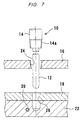
Heretofore, as shown in FIG. 7, a sheath type measuring instrument 10 has a thin linear sheath (metallic protective tube) 12 housing a thermocouple or a thermoresistor in its distal end and filled with an insulation, and a barrel 14 for fixing the sheath 12 while positioning in position. The sheath 12 has a proximal portion telescopically held in the barrel 14 by a spring or the like. For directly measuring the temperature of a measurand 22 having a heat generating region 20, disposed in an outer wall 16 such as an outer casing or the like and covered with an inner wall 18 such as an inner casing or the like, using the sheath type measuring instrument 10, a barrel mount hole 24 for mounting the barrel is bored in the outer wall 16 and a sheath insertion hole 26 for inserting the tip end of the sheath 12 therein is bored in the inner wall 18 and the measurand 22 in alignment with the barrel mount hole 24. With the tip end of the sheath 12 being located in position in the sheath insertion hole 26, an externally threaded tapered surface 14 a on the lower outer circumference of the barrel 14 of the sheath type measuring instrument 10 is threaded into the barrel mount hole 24 in the outer wall 16, thereby fastening the barrel 14 to the outer wall 16 to hold the sheath 12 in position.
According to another scheme, as shown in FIG. 8, a clearance hole 27 having a larger inside diameter than the diameter of the sheath 12 is bored in the outer wall 16, and the barrel 14 of the sheath type measuring instrument 10 is mounted on the outer wall 16 with a flange 28 that is large enough to close the clearance hole 27. The flange 28 attached to the outer wall 16 is positionally adjusted to absorb a positional deviation δ1 between the center O1 of the clearance hole 27 and the center O2 of the sheath insertion hole 26 by bringing the axis of the barrel 14 and the sheath 12 into alignment with the center O2 of the sheath insertion hole 26.
For measuring the temperature of a measurand with the sheath type measuring instrument, if the sheath insertion hole for inserting the tip end of the sheath therein is of an inside diameter that is much greater than the diameter of the sheath, for example, then the temperature cannot accurately be measured because of a heat gradient within the sheath insertion hole. Therefore, the inside diameter of the sheath insertion hole is required to be of substantially the same as the diameter of the sheath.
If the sheath insertion hole is a hole (narrow hole) having substantially the same inside diameter as the diameter of the sheath, then as shown in FIG. 7 referred to above, for example, when the sheath 12 is to be located in position to install the sheath type measuring instrument 10 after boring the barrel mount hole 24 in the outer wall 16 and boring the sheath insertion hole 26 in the inner wall 18 and the measurand 26, the barrel mount hole 24 and the sheath insertion hole 26 need to be highly positionally accurate with respect to each other. Therefore, it may be necessary to take into account a case where the barrel mount hole 24 and the sheath insertion hole 26 are to be machined after the parts are assembled. Specifically, as shown in FIG. 9, in the event that a positional deviation δ2 occurs between the center O3 of the barrel mount hole 24 and the center O4 of the sheath insertion hole 26, even if the positional deviation δ2 is slight, since the axis of the barrel 14 and the sheath 12 is aligned with the center O3 of the barrel mount hole 24, the sheath 12 interferes with the open end of the sheath insertion hole 26. Therefore, the sheath 12 cannot smoothly be inserted into the sheath insertion hole 26. If the sheath 12 is forcibly inserted, it may be deformed or damaged.
If, as shown in FIG. 8, the positional deviation δ1 between the clearance hole 27 bored in the outer wall 16 and the sheath insertion hole 26 bored in the inner wall 18 and the measurand 22 is to be absorbed by the flange 28, then a complex process is required to move the flange 28 to a position where the tip end of the sheath 12 can be inserted into the sheath insertion hole 26 and to position and fix the flange 28, for example.
SUMMARY OF THE INVENTION
The present invention has been made in view of above drawbacks. It is an object of the present invention to provide a sheath type measuring instrument, a bearing with such a sheath type measuring instrument, and a rotary machine with such a bearing, which allow a barrel to be fixed to an outer wall easily and smoothly without the need for boring holes in the outer wall and an inner wall with high positional accuracy and also for a complex process, even if the barrel is to be fixed to the outer wall while the tip end of a sheath is being inserted in a sheath insertion hole bored in the inner wall.
In order to achieve the above object, a sheath type measuring instrument according to the present invention has a sheath having a tip end for being brought closely to or into contact with a measurand for measuring a physical property of the measurand, and a barrel holding a proximal portion of the sheath for movement in a direction perpendicular to an axis of the sheath.
With the above arrangement, even if there is a positional deviation occurring between a barrel mount hole bored in an outer wall and a sheath insertion hole bored in an inner wall, the sheath is translated in the direction perpendicular to the axis thereof by a distance that is commensurate with the positional deviation. Therefore, the positional deviation can be absorbed easily. The sheath type measuring instrument can be mounted in place with the tip end of the sheath being located in place in the sheath insertion hole.
According to the present invention, a bearing for being housed in a bearing casing has a sliding contact member for being held in sliding contact with a rotor and being heated, wherein the bearing has a sheath type measuring instrument including a sheath having a proximal portion held in a barrel for movement in a direction perpendicular to an axis of the sheath, the sheath having a tip end disposed in position in a sheath insertion hole defined in the bearing casing.
With the above arrangement, the temperature of a sliding member exposed to high temperatures, such as a thrust pad of a thrust bearing, for example, can be monitored at all times by the sheath type measuring instrument.
A rotary machine according to the present invention has a bearing housed in a bearing casing and having a sliding contact member for being held in sliding contact with a rotor and being heated, the bearing being disposed in an apparatus casing, and a sheath type measuring instrument having a sheath having a proximal portion held in a barrel for movement in a direction perpendicular to an axis of the sheath. The sheath type measuring instrument is fixed to the apparatus casing by the barrel, the sheath having a tip end disposed in position in a sheath insertion hole defined in the bearing casing.
With the above arrangement, a malfunction of the rotary machine such as a pump or the like can be found early by monitoring at all times the temperature of a sliding member of a bearing which is exposed to high temperatures.
BRIEF DESCRIPTION OF THE DRAWINGS
FIG. 1 is a cross-sectional view of a sheath type measuring instrument according to an embodiment of the present invention;
FIG. 2 is a view illustrative of the manner in which the sheath type measuring instrument shown in FIG. 1 is mounted in place;
FIG. 3 is a cross-sectional view of a pump apparatus as a rotary machine in which sheath type measuring instruments shown in FIG. 1 are mounted;
FIG. 4 is a left side view of the pump apparatus shown in FIG. 3 which incorporates the sheath type measuring instruments shown in FIG. 1 mounted therein;
FIG. 5 is a front view of a bearing cover housing therein a thrust bearing of the pump apparatus shown in FIG. 3 which incorporates the sheath type measuring instruments shown in FIG. 1 mounted therein;
FIG. 6 is a diagram showing the relationship between the thrust bearing, the bearing cover, and the sheath type measuring instrument when the sheath type measuring instrument shown in FIG. 1 is mounted in the pump apparatus shown in FIG. 3;
FIG. 7 is a view schematically showing a conventional sheath type measuring instrument, the view being illustrative of a scheme in which the conventional sheath type measuring instrument is mounted in place;
FIG. 8 is a view schematically showing the conventional sheath type measuring instrument, the view being illustrative of another scheme in which the conventional sheath type measuring instrument is mounted in place; and
FIG. 9 is a view illustrative of a defect of the scheme illustrated in FIG. 7.
DETAILED DESCRIPTION OF THE PREFERRED EMBODIMENT
An embodiment of the present invention will be described below with reference to the drawings.
FIG. 1 shows a sheath type measuring instrument 30 according to an embodiment of the present invention. As shown in FIG. 1, this sheath type measuring instrument 30 has a thin linear sheath (metallic protective tube) 32 housing a thermocouple or a thermoresistor in its distal end and filled with an insulation, and a hollow cylindrical barrel 34 for fixing the sheath 32 while positioning in position. The barrel 34 has an externally threaded tapered surface 34 a on a lower outer circumference thereof and an externally threaded surface 34 b on an upper outer circumference thereof. A substantially cylindrical upper bushing 36 and a substantially cylindrical lower bushing 38 are fitted respectively in upper and lower inner circumferences of the barrel 34.
A flexible coupling 40 comprising bendable metallic bellows made of stainless steel or the like, for example, is disposed in the barrel 34 between the upper bushing 36 and the lower bushing 38. The flexible coupling 40 has an upper end (free end) welded to an upper socket 44 (a first socket) by a welded region 42 and a lower end (proximal end) welded to a lower socket 48 (a second socket) by a welded region 46. The upper socket 44 is welded to the sheath 32 by a welded region 50 while being free with respect to the barrel 34. The lower socket 48 is slidably fitted in the lower bushing 38 while being free with respect to the sheath 32. An O-ring 52 for keeping the interior of the barrel 34 hermetically closed is interposed between the lower socket 48 and the lower bushing 38.
Since the proximal end of the flexible coupling 40 is supported by the barrel 34 while being free with respect to the sheath 32, and the free end of the flexible coupling 40, which is free with respect to the barrel 34 within space 35, is fixed to the sheath 32, the sheath 32 can be translated in a direction perpendicular to the axial direction of the sheath 32 through the flexible coupling 40.
In this embodiment, a spring 54 is interposed between the upper socket 44 and the upper bushing 36. The sheath 32 can be extended from and contracted into the barrel 34 under the resiliency of the spring 54, i.e., the length of the tip end portion of the sheath 32, which extends from the barrel 34, can be adjusted. A stopper 56 is mounted on the lower end of the lower socket 48 for abutting against a smaller-diameter end face of the lower bushing 38 to prevent the lower bushing 38 from moving (being lifted) when the lower socket 48 is moved (lifted) relatively to the lower bushing 38.
A process of mounting the sheath type measuring instrument 30 according to this embodiment by, as with the conventional sheath type measuring instrument shown in FIG. 9, boring the barrel mount hole 24 in the outer wall 16 and the sheath insertion hole 26 in the inner wall 18 and the measurand 22, and locating the tip end of the sheath 32 in position in the sheath insertion hole 26, will be described below with reference to FIG. 2. It is assumed that a positional deviation δ2 occurs between the center O3 of the barrel mount hole 24 and the center O4 of the sheath insertion hole 26.
The sheath 32 extending from the barrel 34 is kept parallel to the barrel 34 and translated in a direction perpendicular to the axis of the sheath 32 by a distance that is commensurate with the positional deviation δ2 between the barrel mount hole 24 and the sheath insertion hole 26 through the flexible coupling 40 housed in the barrel 34, thereby absorbing the positional deviation δ2 with the sheath type measuring instrument 30 itself. Specifically, while the axis of the barrel 34 is being held in alignment with the center O3 of the barrel mount hole 24, the axis of the sheath 32 is brought into alignment with the center O4 of the sheath insertion hole 26. Then, the tip end of the sheath 32 is located in position in the sheath insertion hole 26, and the externally threaded tapered surface 34 a of the barrel 34 is threaded into the barrel mount hole 24 in the outer wall 16, thereby fixing the barrel 34 to the outer wall 16.
Even if there is a positional deviation occurring between the barrel mount hole 24 in the outer wall 16 and the sheath insertion hole 26 in the inner wall 18, the positional deviation can be absorbed easily with the sheath type measuring instrument 30 itself. Accordingly, even if the outer wall 16 and the inner wall 18 are bored without the need for high positional accuracy, the sheath type measuring instrument 30 can be mounted in place while the sheath 32 is being positioned in place. As there is no need for concern over a positional deviation of the holes when the parts are assembled, the assembling efficiency is increased and the time required to assemble the parts is greatly reduced.
FIGS. 3 through 6 show an example in which sheath type measuring instruments 30 shown in FIG. 1 are mounted in a double-suction-type pump apparatus 60 as a rotary machine. As shown in FIG. 3, the double-suction-type pump apparatus 60 (rotary machine) has a pump casing 64 with a volute chamber 62 defined therein. An impeller 68, which is rotatable in response to rotation of a main shaft 66, is disposed in the pump casing 64. The main shaft 66 is coupled to a drive shaft 72 of a motor or the like by a coupling 70. The main shaft 66 has opposite ends rotatably supported by journal bearings 76 as a pair of radial bearings disposed in respective bearing casings 74. A thrust bearing 78 for bearing a thrust load from the main shaft 66 is disposed on an outer side of one of the journal bearings 76 and integrally covered with a bearing cover (apparatus casing) 80.
As shown in detail in FIG. 6, the thrust bearing 78 has a cylindrical bearing casing 82. Thrust pads 86 as sliding contact members are disposed respectively on opposite sides of a thrust collar 84 which serves as a rotor rotatable in unison with the main shaft 66 within the bearing casing 82, the thrust pads 86 being mounted in the casing 82. When the main shaft 66 rotates, the thrust collar (rotor) 84 rotates, and the thrust pads (sliding contact members) 86 are held in sliding contact with the opposite surfaces of the thrust collar 84 for bearing the thrust load from the main shaft 66.
In this embodiment, a plurality of (e.g., six) substantially sectorial thrust pads 86 are disposed on each of the opposite sides of the thrust collar 84 at circumferentially spaced equal intervals. Each of these thrust pads 86 is slightly movable axially. One of the thrust pads 86 positioned each of the opposite sides of the thrust collar 84 is measured for temperature by the sheath type measuring instrument 30. The temperatures of the thrust pads 86, which are held in sliding contact with the thrust collar 84 and heated and hence are exposed to high temperatures during operation of the pump apparatus, are monitored at all times, and changes in the temperatures of the thrust pads 86 are confirmed based on the monitored temperatures for thereby finding early a malfunction of the pump apparatus 60 during its operation. As the sheath type measuring instruments 30 each shown in FIG. 1 are used to measure the temperatures of the thrust pads 86, there is less danger of disconnection than if a thermocouple or a thermoresistor is directly wired to the thrust pads or the like, and the sheath type measuring instruments 30 can be mounted in place with better efficiency.
Specifically, as shown in FIG. 6, a barrel mount hole 88 is bored in the bearing cover (apparatus casing) 80 and a sheath insertion hole 90 is bored in the bearing casing 82 and the thrust pad (sliding contact member) 86 in alignment with the barrel mount hole 88. The tip end of the sheath 82 is located in position in the sheath insertion hole 90, and the barrel 34 of the sheath type measuring instrument 30 is threaded into the barrel mount hole 88 bored in the bearing cover 80, thereby mounting the sheath type measuring instrument 30 in place. In this embodiment, a terminal box 92 having terminals is mounted on the head of the barrel 34.
Even if there is a positional deviation occurring between the center of the barrel mount hole 88 and the center of the sheath insertion hole 90, in the same manner as described above, the sheath 32 is translated in a direction perpendicular to the axis thereof by a distance that is commensurate with the positional deviation, so that the positional deviation can be absorbed easily with the sheath type measuring instrument 30 itself. Accordingly, even if the bearing cover 80 and the bearing casing 82 are bored without the need for high positional accuracy, the sheath type measuring instrument 30 can be mounted in place while the sheath 32 is being positioned in place. As there is no need for concern over a positional deviation of the holes when the parts are assembled, the assembling efficiency is increased and the time required to assemble the parts is greatly reduced.
In this embodiment, the double-suction-type pump apparatus has been used as a rotary machine. However, the present invention is also applicable to any of other pump apparatus or rotary machines other than pump apparatus.
With the sheath type measuring instrument according to the present invention, even if there is a positional deviation occurring between the barrel mount hole bored in the outer wall and the sheath insertion hole bored in the inner wall, the positional deviation can be absorbed easily with the sheath type measuring instrument itself. Accordingly, even if the outer wall and the inner wall are bored without the need for high positional accuracy, the sheath type measuring instrument can be mounted in place while the sheath is being positioned in place. As there is no need for concern over a positional deviation of the holes when the parts are assembled, the assembling efficiency is increased and the time required to assemble the parts is greatly reduced.
With the bearing according to the present invention, the temperature of a sliding member exposed to high temperatures, such as a thrust pad of a thrust bearing or the like, for example, can be monitored at all times by the sheath type measuring instrument.
With the rotary machine according to the present invention, the temperature of a sliding member of a bearing, which is exposed to high temperatures, can be monitored at all times, and can be prevented from increasing thereby to prevent a rotary machine such as a pump or the like from being lowered in performance.

Claims (3)

1. A sheath type measuring instrument comprising:
a barrel;
a sheath having a tip end for being brought closely to or into contact with a measurand for measuring a physical property of the measurand;
a first socket, disposed in said barrel, holding a proximal portion of said sheath;
a second socket fitted in said barrel slidably, and
a flexible coupling having a first end fixed to said first socket and a second end fixed to said second socket, wherein a space within said barrel surrounding said first socket and said flexible coupling permits said first socket and said sheath to move in a direction perpendicular to an axis of said sheath.
2. A sheath type measuring instrument according to claim 1, further comprising:
a spring disposed in said barrel between one end of said barrel and said first socket.
3. A sheath type measuring instrument according to claim 1, further comprising:
an O-ring disposed between said second socket and said barrel.
US11/311,426 2004-12-22 2005-12-20 Sheath type measuring instrument, bearing and rotary machine Active 2029-05-26 US7950848B2 (en)

Applications Claiming Priority (2)

Application Number Priority Date Filing Date Title
JP2004371712A JP4606867B2 (en) 2004-12-22 2004-12-22 Sheath type measuring instrument, bearing, and rotating machine
JP2004-371712 2004-12-22

Publications (2)

Publication Number Publication Date
US20060185450A1 US20060185450A1 (en) 2006-08-24
US7950848B2 true US7950848B2 (en) 2011-05-31

Family

ID=36732039

Family Applications (1)

Application Number Title Priority Date Filing Date
US11/311,426 Active 2029-05-26 US7950848B2 (en) 2004-12-22 2005-12-20 Sheath type measuring instrument, bearing and rotary machine

Country Status (2)

Country Link
US (1) US7950848B2 (en)
JP (1) JP4606867B2 (en)

Cited By (3)

* Cited by examiner, † Cited by third party
Publication number Priority date Publication date Assignee Title
US20090266169A1 (en) * 2006-11-07 2009-10-29 Universite De Reims Champagne Ardenne Device and method for monitoring the vibratory condition of a rotating machine
US20120063488A1 (en) * 2009-05-08 2012-03-15 Shibaura Electronics Co., Ltd. Temperature sensor and temperature sensor system
US20130322489A1 (en) * 2011-02-23 2013-12-05 Heraeus Electro-Nite International N.V. Sensor arrangement for the measuring of parameters in melted material

Families Citing this family (7)

* Cited by examiner, † Cited by third party
Publication number Priority date Publication date Assignee Title
NZ555385A (en) * 2007-05-25 2009-09-25 Senztek Holdings Ltd Sensor mounting assembly
JP4905290B2 (en) * 2007-08-09 2012-03-28 住友電気工業株式会社 Temperature measuring device for semiconductor manufacturing apparatus and semiconductor manufacturing apparatus equipped with the same
US20120023967A1 (en) * 2010-07-30 2012-02-02 Dede Brian C Auxiliary power unit with hot section fire enclosure arrangement
US9523650B2 (en) * 2013-09-06 2016-12-20 Conax Technologies Llc Spring loaded exhaust gas temperature sensor assembly
FR3031177B1 (en) * 2014-12-31 2017-02-10 Areva Nc TEMPERATURE MEASURING ROD, WITH EASILY REPLACABLE THERMOCOUPLE
JP7203628B2 (en) * 2019-02-13 2023-01-13 三菱重工マリンマシナリ株式会社 Sensor installation structure and bearing with this
CN113203501B (en) * 2021-05-20 2023-05-12 苏州热工研究院有限公司 Nuclear power main pump thrust shoe temperature measurement probe assembly verification method

Citations (35)

* Cited by examiner, † Cited by third party
Publication number Priority date Publication date Assignee Title
US2681565A (en) * 1951-06-09 1954-06-22 A V Roe Canada Ltd Means for thrust measurement
US3450056A (en) * 1967-07-18 1969-06-17 Westinghouse Electric Corp Canned motor pump
US3507577A (en) * 1967-06-13 1970-04-21 Judson S Swearingen Gas expansion and heat and pressure power generating combination
US3516873A (en) * 1967-04-13 1970-06-23 Thermo Electric Co Inc Spring-loaded thermocouple
US3804552A (en) * 1972-07-05 1974-04-16 Textron Inc Four blade main rotor control power coupling
DE2534655A1 (en) * 1975-08-02 1977-02-17 Henning G Dr Ing Bartels Immersion pump with axially sliding rotor - has pipe for connecting inlet and thrust bearing for thrust compensation
US4132114A (en) * 1977-03-14 1979-01-02 Westinghouse Electric Corp. Temperature probe assembly for gas turbine engine
US4181397A (en) * 1977-03-11 1980-01-01 Smiths Industries Limited Fibre-optic cable
US4241603A (en) * 1979-02-02 1980-12-30 The Bendix Corporation Aircraft brake thermal sensor
US4355912A (en) * 1980-09-12 1982-10-26 Haak Raymond L Spring loaded sensor fitting
JPS6015637U (en) 1983-07-08 1985-02-02 株式会社日立製作所 temperature measuring device
US4734994A (en) * 1986-12-22 1988-04-05 Gte Valeron Corporation Probe having a plurality of hinged plates
US4850457A (en) * 1987-10-07 1989-07-25 Allied-Signal Inc. Electrically actuated disc brake
US4852451A (en) * 1988-11-02 1989-08-01 Rogers Ronald O Powder level sensing device
US4889483A (en) * 1984-09-06 1989-12-26 Granco-Clark, Inc. Temperature controlled probe assembly
JPH028721A (en) * 1988-06-28 1990-01-12 Kawatetsu Techno Res Corp Method and apparatus for measuring temperature of metallic running body
US5128688A (en) * 1990-11-27 1992-07-07 Sperry Marine, Inc. Mast translation and rotation drive system utilizing a ball drive screw and nut assembly
US5146244A (en) * 1990-01-23 1992-09-08 Rosemount Inc. Window purging system for a combustion instrument
US5277496A (en) * 1990-10-17 1994-01-11 Ametek, Inc. High temperature optical probe
US5509310A (en) * 1994-03-18 1996-04-23 Reliance Electric Industrial Company Bearing assemblies including proximity probes
US5601365A (en) * 1994-09-26 1997-02-11 Ford Motor Company Sensing device for controlling electromagnetic field generator for adhesive curing
US5632557A (en) * 1994-12-16 1997-05-27 Weed Instrument Company, Inc. Modular temperature sensing apparatus
US5639108A (en) * 1994-07-13 1997-06-17 Salomon S.A. Boot-retention element assembly, particularly for skiing
JPH09304230A (en) * 1996-05-14 1997-11-28 Meidensha Corp Brake tester
US5707152A (en) * 1986-01-15 1998-01-13 Krywitsky; Lee A. Method for using reusable pipe union and pipe cap assembly for wide thermal cycling
JPH109966A (en) 1996-06-26 1998-01-16 Ishikawajima Harima Heavy Ind Co Ltd Thermometer for pipe
US5862890A (en) * 1996-01-16 1999-01-26 Mcdonnell Douglas Corporation Restrained aircraft brake apparatus
US6094904A (en) * 1998-07-16 2000-08-01 United Technologies Corporation Fuel injector with a replaceable sensor
US6161962A (en) * 1996-09-13 2000-12-19 The Timken Company Bearing with sensor module
US6193414B1 (en) * 1998-01-06 2001-02-27 Alfiero Balzano Dual protected instant temperature detector
US6220749B1 (en) * 1999-04-02 2001-04-24 Carrier Corporation Self-adjusting temperature sensor
US20040258130A1 (en) * 2001-04-20 2004-12-23 Luxtron Corporation In situ optical surface temperature measuring techniques and devices
US7121013B2 (en) * 2001-04-11 2006-10-17 Dr. Johannes Heidenhain Gmbh Length sensor
US7222704B2 (en) * 2002-02-01 2007-05-29 Bae Systems Plc Damping of vibrations
US7448854B2 (en) * 2004-08-30 2008-11-11 Lord Corporation Helicopter vibration control system and rotary force generator for canceling vibrations

Family Cites Families (4)

* Cited by examiner, † Cited by third party
Publication number Priority date Publication date Assignee Title
JPS465195Y1 (en) * 1967-04-19 1971-02-23
JPS54171387U (en) * 1978-05-24 1979-12-04
JPS5768532U (en) * 1980-10-15 1982-04-24
JPH05184103A (en) * 1991-12-27 1993-07-23 Fuji Electric Co Ltd Mounting structure for thermometer element of rotary electric machine

Patent Citations (36)

* Cited by examiner, † Cited by third party
Publication number Priority date Publication date Assignee Title
US2681565A (en) * 1951-06-09 1954-06-22 A V Roe Canada Ltd Means for thrust measurement
US3516873A (en) * 1967-04-13 1970-06-23 Thermo Electric Co Inc Spring-loaded thermocouple
US3507577A (en) * 1967-06-13 1970-04-21 Judson S Swearingen Gas expansion and heat and pressure power generating combination
US3450056A (en) * 1967-07-18 1969-06-17 Westinghouse Electric Corp Canned motor pump
US3804552A (en) * 1972-07-05 1974-04-16 Textron Inc Four blade main rotor control power coupling
DE2534655A1 (en) * 1975-08-02 1977-02-17 Henning G Dr Ing Bartels Immersion pump with axially sliding rotor - has pipe for connecting inlet and thrust bearing for thrust compensation
US4181397A (en) * 1977-03-11 1980-01-01 Smiths Industries Limited Fibre-optic cable
US4132114A (en) * 1977-03-14 1979-01-02 Westinghouse Electric Corp. Temperature probe assembly for gas turbine engine
US4241603A (en) * 1979-02-02 1980-12-30 The Bendix Corporation Aircraft brake thermal sensor
US4355912A (en) * 1980-09-12 1982-10-26 Haak Raymond L Spring loaded sensor fitting
JPS6015637U (en) 1983-07-08 1985-02-02 株式会社日立製作所 temperature measuring device
US4889483A (en) * 1984-09-06 1989-12-26 Granco-Clark, Inc. Temperature controlled probe assembly
US5707152A (en) * 1986-01-15 1998-01-13 Krywitsky; Lee A. Method for using reusable pipe union and pipe cap assembly for wide thermal cycling
US4734994A (en) * 1986-12-22 1988-04-05 Gte Valeron Corporation Probe having a plurality of hinged plates
US4850457A (en) * 1987-10-07 1989-07-25 Allied-Signal Inc. Electrically actuated disc brake
JPH028721A (en) * 1988-06-28 1990-01-12 Kawatetsu Techno Res Corp Method and apparatus for measuring temperature of metallic running body
US4852451A (en) * 1988-11-02 1989-08-01 Rogers Ronald O Powder level sensing device
US5146244A (en) * 1990-01-23 1992-09-08 Rosemount Inc. Window purging system for a combustion instrument
US5277496A (en) * 1990-10-17 1994-01-11 Ametek, Inc. High temperature optical probe
US5128688A (en) * 1990-11-27 1992-07-07 Sperry Marine, Inc. Mast translation and rotation drive system utilizing a ball drive screw and nut assembly
US5509310A (en) * 1994-03-18 1996-04-23 Reliance Electric Industrial Company Bearing assemblies including proximity probes
US5639108A (en) * 1994-07-13 1997-06-17 Salomon S.A. Boot-retention element assembly, particularly for skiing
US5601365A (en) * 1994-09-26 1997-02-11 Ford Motor Company Sensing device for controlling electromagnetic field generator for adhesive curing
US5632557A (en) * 1994-12-16 1997-05-27 Weed Instrument Company, Inc. Modular temperature sensing apparatus
US5862890A (en) * 1996-01-16 1999-01-26 Mcdonnell Douglas Corporation Restrained aircraft brake apparatus
JPH09304230A (en) * 1996-05-14 1997-11-28 Meidensha Corp Brake tester
JPH109966A (en) 1996-06-26 1998-01-16 Ishikawajima Harima Heavy Ind Co Ltd Thermometer for pipe
US6161962A (en) * 1996-09-13 2000-12-19 The Timken Company Bearing with sensor module
US6193414B1 (en) * 1998-01-06 2001-02-27 Alfiero Balzano Dual protected instant temperature detector
US6094904A (en) * 1998-07-16 2000-08-01 United Technologies Corporation Fuel injector with a replaceable sensor
US6220749B1 (en) * 1999-04-02 2001-04-24 Carrier Corporation Self-adjusting temperature sensor
US7121013B2 (en) * 2001-04-11 2006-10-17 Dr. Johannes Heidenhain Gmbh Length sensor
US20040258130A1 (en) * 2001-04-20 2004-12-23 Luxtron Corporation In situ optical surface temperature measuring techniques and devices
US7080940B2 (en) * 2001-04-20 2006-07-25 Luxtron Corporation In situ optical surface temperature measuring techniques and devices
US7222704B2 (en) * 2002-02-01 2007-05-29 Bae Systems Plc Damping of vibrations
US7448854B2 (en) * 2004-08-30 2008-11-11 Lord Corporation Helicopter vibration control system and rotary force generator for canceling vibrations

Non-Patent Citations (1)

* Cited by examiner, † Cited by third party
Title
Japanese Office Action dated Apr. 27, 2010, issued in corresponding Japanese Patent Application No. 2004-371712.

Cited By (6)

* Cited by examiner, † Cited by third party
Publication number Priority date Publication date Assignee Title
US20090266169A1 (en) * 2006-11-07 2009-10-29 Universite De Reims Champagne Ardenne Device and method for monitoring the vibratory condition of a rotating machine
US8234925B2 (en) * 2006-11-07 2012-08-07 Universite De Reims Champagne-Ardenne Device and method for monitoring the vibratory condition of a rotating machine
US20120063488A1 (en) * 2009-05-08 2012-03-15 Shibaura Electronics Co., Ltd. Temperature sensor and temperature sensor system
US8419275B2 (en) * 2009-05-08 2013-04-16 Shibaura Electronics Co., Ltd. Temperature sensor and temperature sensor system
US20130322489A1 (en) * 2011-02-23 2013-12-05 Heraeus Electro-Nite International N.V. Sensor arrangement for the measuring of parameters in melted material
US9366578B2 (en) * 2011-02-23 2016-06-14 Heraeus Electro-Nite International N.V. Sensor arrangement for the measuring of parameters in melted material

Also Published As

Publication number Publication date
JP2006177793A (en) 2006-07-06
US20060185450A1 (en) 2006-08-24
JP4606867B2 (en) 2011-01-05

Similar Documents

Publication Publication Date Title
US7950848B2 (en) Sheath type measuring instrument, bearing and rotary machine
US4495810A (en) Probe mounting system
JP5607285B2 (en) Bearing device
US20100215491A1 (en) Rotor assembly
JP5426565B2 (en) Lubricated screw compressor
US7414413B2 (en) Blade tip clearance probe holder and a method for measuring blade tip clearance
US20100239204A1 (en) Bearing temperature monitoring device and bearing device provided with the monitoring device
US11496021B2 (en) Electric motor having a rotor shaft and a first and a second bearing
CN107631840B (en) A kind of labyrinth seal experimental provision with eccentric adjustment function
JP2011226642A (en) Structural unit for angle measuring device
JP3847796B2 (en) Vacuum pump with backup bearing device
JP2011527423A (en) Rotation transducer and rotation transducer product series
JP2000263375A (en) Spindle device
KR20000077397A (en) Discharge-pumped excimer laser device
JP2005326030A (en) Damping device
JP2000208078A (en) Rolling bearing for rotating anode x-ray tube
JP2005106653A (en) Rotation amount detection device
JP2006088245A (en) Spindle apparatus
JP2007147312A (en) Nmr device
JP2002005164A (en) Spindle device
JP4155120B2 (en) X-ray tube and X-ray tube device
JP5626708B2 (en) Bearing device
CN213748813U (en) Bimetal thermometer
SU1296756A1 (en) Bearing unit
JP5821314B2 (en) Torque sensor

Legal Events

Date Code Title Description
AS Assignment

Owner name: OKAZAKI MANUFACTURING COMPANY, JAPAN

Free format text: ASSIGNMENT OF ASSIGNORS INTEREST;ASSIGNORS:KIMURA, SAHO;SUGAYA, TAKASHI;KAZAOKA, MANABU;AND OTHERS;REEL/FRAME:017488/0134

Effective date: 20060113

Owner name: EBARA CORPORATION, JAPAN

Free format text: ASSIGNMENT OF ASSIGNORS INTEREST;ASSIGNORS:KIMURA, SAHO;SUGAYA, TAKASHI;KAZAOKA, MANABU;AND OTHERS;REEL/FRAME:017488/0134

Effective date: 20060113

STCF Information on status: patent grant

Free format text: PATENTED CASE

FPAY Fee payment

Year of fee payment: 4

MAFP Maintenance fee payment

Free format text: PAYMENT OF MAINTENANCE FEE, 8TH YEAR, LARGE ENTITY (ORIGINAL EVENT CODE: M1552); ENTITY STATUS OF PATENT OWNER: LARGE ENTITY

Year of fee payment: 8

MAFP Maintenance fee payment

Free format text: PAYMENT OF MAINTENANCE FEE, 12TH YEAR, LARGE ENTITY (ORIGINAL EVENT CODE: M1553); ENTITY STATUS OF PATENT OWNER: LARGE ENTITY

Year of fee payment: 12