US7954335B2 - Atmospheric water harvesters with variable pre-cooling - Google Patents
Atmospheric water harvesters with variable pre-cooling Download PDFInfo
- Publication number
- US7954335B2 US7954335B2 US12/418,077 US41807709A US7954335B2 US 7954335 B2 US7954335 B2 US 7954335B2 US 41807709 A US41807709 A US 41807709A US 7954335 B2 US7954335 B2 US 7954335B2
- Authority
- US
- United States
- Prior art keywords
- awh
- air
- cooling
- airflow passageway
- heat exchanger
- Prior art date
- Legal status (The legal status is an assumption and is not a legal conclusion. Google has not performed a legal analysis and makes no representation as to the accuracy of the status listed.)
- Expired - Fee Related, expires
Links
Images


Classifications
-
- E—FIXED CONSTRUCTIONS
- E03—WATER SUPPLY; SEWERAGE
- E03B—INSTALLATIONS OR METHODS FOR OBTAINING, COLLECTING, OR DISTRIBUTING WATER
- E03B3/00—Methods or installations for obtaining or collecting drinking water or tap water
- E03B3/28—Methods or installations for obtaining or collecting drinking water or tap water from humid air
-
- F—MECHANICAL ENGINEERING; LIGHTING; HEATING; WEAPONS; BLASTING
- F28—HEAT EXCHANGE IN GENERAL
- F28F—DETAILS OF HEAT-EXCHANGE AND HEAT-TRANSFER APPARATUS, OF GENERAL APPLICATION
- F28F17/00—Removing ice or water from heat-exchange apparatus
- F28F17/005—Means for draining condensates from heat exchangers, e.g. from evaporators
-
- Y—GENERAL TAGGING OF NEW TECHNOLOGICAL DEVELOPMENTS; GENERAL TAGGING OF CROSS-SECTIONAL TECHNOLOGIES SPANNING OVER SEVERAL SECTIONS OF THE IPC; TECHNICAL SUBJECTS COVERED BY FORMER USPC CROSS-REFERENCE ART COLLECTIONS [XRACs] AND DIGESTS
- Y02—TECHNOLOGIES OR APPLICATIONS FOR MITIGATION OR ADAPTATION AGAINST CLIMATE CHANGE
- Y02A—TECHNOLOGIES FOR ADAPTATION TO CLIMATE CHANGE
- Y02A20/00—Water conservation; Efficient water supply; Efficient water use
Definitions
- the invention relates to atmospheric moisture harvesting and improvements in the efficiency of condensing water from air and in apparatus relating thereto. More particularly, the invention provides improved energy efficient extraction of water from air, particularly in outdoor settings and over a range of relative humidity.
- Atmospheric water harvesting is intended to produce water in the general vicinity of its place of use. Producing potable water near its place of use removes the requirement for either temporary or fixed water delivery systems such as pipelines and canals or temporary delivery systems such as bulk motorized water tankers. Production of high-quality water at or near its place of use is superior to transporting bottled drinking water, which requires substantial consumption of energy for delivery and waste disposal. Water harvesters are also superior environmentally because water bottle disposal is not an issue; water bottles are reused in conjunction with water harvesting. In addition, the water produced from suitably designed and operated water harvesters is pure and suitable and safe for drinking with very little treatment.
- Water harvesting has not generally been regarded as a replacement for conventional piped water supplies because of its relatively higher cost and lower volumes.
- water harvesting has not generally been regarded as a replacement for conventional piped water supplies because of its relatively higher cost and lower volumes.
- condensation of water is achieved by providing and maintaining a chilled surface upon which water from moist air condenses.
- This is well known as a byproduct of chilling air, as in air conditioning systems in which chilling the air is the objective or in air dehumidification systems in which the objective is to achieve relative dryness of the exhaust air.
- water produced as a byproduct in these systems is more expensive to produce than that which is produced in a water harvester apparatus that is optimized for energy efficient water production by not overcooling air or water.
- byproduct water quality is generally not suitable for drinking, and can be dangerous, without additional treatment that is not provided for by an apparatus that does not have water production as a primary objective.
- Water harvesting apparatus that has been specifically designed to produce water from air already exists (but without the efficiency and sophistication of this invention) which allows the production of water of the same or superior quality as bottled water but without the delivery or environmental waste issues and in quantities that are suitable for personal or family use on a regular and extended basis. Water harvesting provides high quality potable water without the continued cost of producing bottles directly in proportion to the quantity of water delivered, at a lower cost than bottled water.
- the present invention provides improved apparatus and methods for condensing water from air. These improvements involve, but are not limited to, an improved water condenser, improved condenser airflow control, a variable speed air impeller, forced air or conductive cooling of all heat-producing parts of the system, new intake air controls, and provision for system-controlled on/off switching for the compressor.
- the apparatus is robustly designed and constructed, is resistant to common handling vibration and shock, and is meant to be moved by hand locally although it may also be fixed.
- the apparatus is intended for use either outdoors or indoors in a semi-autonomous mode, and where air quality is generally good. Water is pumped from a removable collection tank underneath the evaporator into which water has flowed by gravity, either directly or through a water treatment system to the user. Although the water exiting the water harvester has the character of distilled water and is very pure, for prolonged drinking of this water alone, some of the produced water should be remineralized.
- Preferred embodiments are reconfigurable between at least two operational configurations such that to varying degrees incoming air may be pre-cooled, before it passes over a cooling member, by heat exchange with colder air that has already flowed over the cooling member.
- FIG. 1 is schematic plan view of a first embodiment of an atmospheric water harvester according to the invention
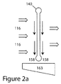
- FIGS. 2 a and 2 b are schematic side views of two alternative orientations, respectively, of a heat exchanger/evaporator used in an atmospheric water harvester according to the invention
- FIGS. 3 and 4 are schematic plan views of second and third embodiments, respectively, of an atmospheric water harvester according to the invention, which second and third embodiments are generally similar to the first embodiment shown in FIG. 1 ;
- FIGS. 5 and 6 are schematic plan views of a fourth embodiment of an atmospheric water harvester according to the invention illustrating the atmospheric water harvester in two different operational configurations;
- FIG. 7 is a schematic end view illustrating a variant of the embodiment of an atmospheric water harvester shown in FIGS. 5 and 6 ;
- FIG. 8 is a schematic plan view illustrating a variant of the embodiment of an atmospheric water harvester shown in FIGS. 5 and 6 ;
- FIGS. 9 and 10 are schematic views (either plan or side elevation; either orientation would be acceptable) of a fifth embodiment of an atmospheric water harvester according to the invention illustrating the atmospheric water harvester in two different operational configurations;
- FIGS. 11 and 12 are schematic views (either plan or side elevation; either orientation would be acceptable) of a sixth embodiment of an atmospheric water harvester according to the invention illustrating the atmospheric water harvester in two different operational configurations;
- FIGS. 13 and 14 are schematic diagrams illustrating so-called “split-condenser” refrigeration systems with the condensers arranged in parallel and in series, respectively, that can be incorporated into any of the atmospheric water harvester embodiments disclosed herein.
- FIG. 1 shows a first embodiment 100 of an atmospheric water harvester (AWH) according to the invention.
- the apparatus for drawing in and exhausting air and refrigeration causes water vapor to be condensed into liquid water within an enclosed apparatus so that it can be collected.
- the apparatus 100 may be placed out-of-doors, where it is surrounded by moist air.
- Ambient air 102 is drawn into the AWH 100 under suction and expelled under pressure.
- This AWH 100 includes an airflow system having an intake 105 ; an air filter 110 ; and air passages 116 , 120 upstream from an impeller or fan 125 .
- the impeller/fan 125 is responsible for drawing air into and forcing it through the apparatus 100 and into an exhaust chamber 135 , from which the air exits through vents 138 (venting air is indicated by dashed-stem arrows) in the external vented wall 137 of the high-pressure exhaust chamber 135 .
- the refrigeration system in general includes an evaporator (cooling member) 140 in which liquid refrigerant is allowed to vaporize, thereby causing the evaporator 140 to become cold and cooling the air passing across it so as to condense water from the air; and a compressor 150 , in which the refrigerant gas from the evaporator 140 is compressed into a liquid by the combination of higher pressure and cooling of the refrigerant by air forced through a condenser 145 .
- evaporator cooling member
- compressor 150 in which the refrigerant gas from the evaporator 140 is compressed into a liquid by the combination of higher pressure and cooling of the refrigerant by air forced through a condenser 145 .
- Ambient air 102 is drawn in through the filter assembly 110 , which may include more than one filter or type of filter, into the pre-evaporator air passage 116 .
- Water is condensed from the air on the evaporator/heat exchanger 140 as the air is pulled through it. Condensation on the evaporator is the key process of atmospheric water harvesting. The condensation process is made as efficient as possible by using a high-thermal-transfer heat exchanger for the evaporator, for instance, a narrow-bore PF 2 heat exchanger manufactured by the Modine Manufacturing Company.
- a coating is applied to the evaporator 140 .
- the coating also may have antibacterial properties.
- examples of this type of coating are a silver ion-containing epoxy available from Burke Industrial Coatings and another (Alcoat 5000 or similar) available from Circle-Prosco that also offers corrosion protection and may assist shedding of water from the condensing surface of the evaporator 140 .
- a fixed or a variable speed compressor may be used.
- a fixed speed compressor which is the simplest type and is most commonly used in refrigeration apparatus, is used.
- Such compressors are cycled on and off to minimize their running time. They are commonly operated along with a temperature-sensing device 155 that measures and controls the system superheat, which is the difference between the temperature of the gas entering the compressor 150 and the evaporation temperature of the liquid refrigerant within the evaporator 140 .
- This device 155 e.g., a thermostatic expansion valve (TXV or TEV), amongst other types of electronic and mechanical devices
- TXV or TEV thermostatic expansion valve
- variable speed compressor 150 In an alternate configuration, a variable speed compressor 150 is used, which runs almost continuously but only as fast as necessary to maintain the desired pressure differential between the evaporator 140 and the condenser 145 .
- a temperature-sensing device 155 that measures and controls the system superheat may be used with this sort of variable-speed compressor as well.
- a cut-off switch (not shown here), which is operated by sensors that detect freeze-up on the evaporator, turns off the compressor to allow ice to melt before restarting.
- the evaporator 140 is in a vertical orientation, as shown in FIG. 2 a .
- Water (black, single stem arrows) 158 formed on the upper evaporator surfaces flows down over the subjacent evaporator surfaces, which has the effect of amalgamating the water into rivulets as well as droplets as it flows from the evaporator 140 to the subjacent water collector 163 .
- rivulets are more coherent water masses with higher mass to surface area ratios, they are less liable to lose water to the airstream moving at about a 90 degree angle across the flowing condensed water.
- the water passing from the evaporator 140 to the water collection tank 163 may be only very slightly affected by air flow, which does not impinge toward the water collection tank 163 .
- water is removed from a horizontally oriented evaporator (also labeled 140 ) by forced air moving in the same direction as the condensed water separating from the evaporator 140 .
- Water droplets 146 flow directly downward (single-stem black arrows) under the combined influence of gravity and forced air into the water collection tank 163 .
- Water is more rapidly removed following condensation, which may have the result of reducing overcooling of already condensed water and allowing better heat transfer than in the case of coalescing water flowing over the evaporator. This is because water on the evaporator 140 acts as an insulator against heat transfer between the evaporator surface and the moist air 114 .
- Water that has condensed on the evaporator 140 flows downward by gravity into a water collection region tank 163 beneath the evaporator and then into a removable water collection tank (not shown) that is from five to ten gallons or greater in capacity. Multiple tanks allow users to carry water from the water harvester. Alternatively, water may be pumped from the collection tank by a pump 167 , located in the body of the AWH, through an industry-standard replaceable water filter 170 that is located in a compartment 175 that is isolated from the airflow passages within the apparatus. Treated water 190 that has passed through the water treatment system 170 remains under pressure after passing through the filter and exits from ports (not shown) at either or both the top and sides of the apparatus 100 . (A straight-through water filter body without a filter may be used to produce water that is to be used for industrial purposes or that is otherwise not required to be treated to drinking water standards.)
- Air exiting from the evaporator on which water has condensed then passes into an air passage 120 under suction caused by the fan/impeller 125 .
- the air from the fan/impeller 125 then passes through a downstream air passage 130 and through the vaned condenser 145 , where the air cools the compressed refrigerant that is being pumped to the condensor 145 from the compressor 150 .
- the exhaust air passes into an exhaust chamber 135 from which it is exhausted through louvers in the walls of the AWH 100 , the approximate locations of which are shown by arrows.
- the impeller or fan 125 is capable of running at variable speed, which is controlled by varying electrical current or voltage. This allows the impeller or fan to force air though the apparatus at different velocities to optimize water production on the evaporator with respect to the electrical energy consumed.
- a variable speed impeller or fan allows the airflow over the evaporator to be varied, optimizing water production by, for instance, increasing fan speed for high humidity air or preventing or remediating unintended freeze-up where slower airflow could otherwise allow the air to reach a dew point below freezing.
- the fan or impeller may be fixed speed, which may be less efficient under a wide range of input air temperature and humidity conditions but less expensive to implement and not significantly more expensive to operate under consistently humid conditions such as may be found on tropical, low-lying, smaller islands.
- Sealed electronic controls and computer systems that control the refrigeration and airflow system for all embodiments of this invention are integrated in a control pad (not shown) that is located in the top cover of the water harvester for easy operation.
- the bottom surface of the electronic control pad is a conduction heat exchanger that is exposed to the cold airflow stream upstream and/or downstream from the condenser.
- the compressor 150 is located within the exhaust air chamber 135 .
- a compressor is used that is designed to be cooled internally, for instance using refrigerant discharge inside the compressor, there is no need for other cooling of the compressor. With that type of compressor, it is possible to insulate it with noise-absorbing material for quieter operation.
- the air within this chamber is slightly over-pressured with respect to ambient air outside the apparatus, which allows for distribution of air within the chamber 135 in the direction of sidewall vents. Air vents that form a large proportion of the side of the enclosure are located generally in the exterior sidewall 137 of the exhaust chamber 135 (exhaust air shown by black arrows but actual vents may be widespread in the wall) in order to allow air to vent from the apparatus.
- FIGS. 3 and 4 Two further embodiments 200 , 300 will be described with reference to FIGS. 3 and 4 , respectively, in which there are slight variations in the handling of air within the AWH following extraction of water from it.
- similar system components are similarly numbered, but increased to the corresponding hundreds series to “match” the embodiment number 200 , 300 , 400 .
- the similarly numbered components are the same as or generally similar to those described above and may have similar attributes.
- FIG. 3 shows airflow around the compressor 250 from the central part of the exhaust chamber 235 created by locating louvered sidewall vents 295 “downstream” from the compressor 250 . This configuration forces air to pass the compressor 250 in exiting from the exhaust chamber 235 .
- an internal partition 311 isolates the compressor 350 from the exhaust chamber 335 . In this configuration, vents 313 in the outer hull of the AWH 300 allow air to be pulled in by suction into the air passage 320 upstream from the impeller 325 .
- the three embodiments 100 , 200 , 300 that have been described above will work best in high relative humidity (RH) conditions.
- RH relative humidity
- condensation on the evaporator takes place by reducing the temperature of the humid air to the point where condensation initiates.
- intake air is at a high humidity, for instance in excess of 85% RH, water will begin to condense with relatively little energy consumed by chilling.
- the sensible heat of the humid air (which is the term applied to heat associated with temperature change) must be removed to lower the temperature of the air slightly and bring the air to 100% RH locally, at which point condensation is initiated.
- the latent heat (which is that required to cause the water vapor to condense to liquid water) is removed by heat exchange on the evaporator. Following the initiation of condensation, both sensible heat and latent heat are removed from the air being processed in the AWH as the air temperature is further reduced slightly and water is condensed and extracted.
- RH is low, on the other hand, it is beneficial to be able to remove sensible heat before the air reaches the evaporator so that the cooling potential of the evaporator continues to remove a minimum of sensible heat and a maximum of latent heat, which has the effect of maintaining the energy efficiency of water production. (High humidity ambient air requires very little additional cooling to initiate condensation.)
- a variable pre-cooling embodiment 400 of an AWH which is configured to operate well under low as well as high ambient RH conditions and preferably at RH points in between, is illustrated in FIGS. 5 and 6 .
- the embodiment 400 includes a variable flow geometry thermal economizer section 417 located upstream of the impeller 425 and its inlet air passageway 420 .
- the thermal economizer section 417 is suitably housed within a forward extension of the AWH housing and includes an air-to-air heat exchanger 456 located between the evaporator 440 (i.e., downstream from the evaporator) and the impeller 425 (i.e., upstream of the impeller).
- the heat exchanger 456 is directly connected to the evaporator 440 and the impeller entry air passageway 420 , or is connected via ducting to those components, such that air does not seep out from between the evaporator and the heat exchanger or from between the heat exchanger and the impeller.
- a preferred air-to-air heat exchanger 456 is fabricated from thin-walled tubes (e.g., as available from Cesarroni Technologies); from thin-walled corrugated plastic plate (e.g., as available from Innergy Tech, AB Segerfroejd, or Greenbox); or from corrugated metal plate (e.g., as available from Xetex and Des Champs Technology).
- such air-to-air heat exchangers include two sets (at least) of interleaved flow passageways that are typically arranged perpendicularly to each other.
- the heat exchanger 456 is arranged with 1) a first set of heat transfer flow passageways (not illustrated specifically) oriented longitudinally, i.e., generally aligned with the main or overall direction of flow through the AWH 400 ; and 2) a second set of heat transfer flow passageways (not illustrated specifically) that are oriented transverse to the first set of heat transfer flow passageways, i.e., laterally as in the embodiment 400 shown in FIGS. 5 and 6 or vertically.
- the air intake of the AWH 400 i.e., the entrance to the thermal economizer section 417 , is configured to regulate the amount (if any) of air that flows through the second, transverse set of heat exchanger flow passageways.
- a motorized sliding panel 446 mounted in a support or frame 433 , is provided near the entrance to the thermal economizer section 417 , and an airway partition 438 extends from a lateral mid-location—suitably but not necessarily the center—of the panel support or frame 433 to an end of the evaporator 440 .
- the panel 446 extends vertically from the top to the bottom of the thermal economizer section entrance; laterally, assuming the airway partition 438 abuts the frame 433 at the lateral center of the AWH 400 , the panel 446 is slightly wider than half the width of the thermal economizer section entrance.
- a first inlet aperture 402 is formed on the opposite side of the airway partition 433 .
- the air then turns and flows through the evaporator 440 , which cools/chills the air to condense moisture out of it, before the air flows through the longitudinal set of air passageways through the heat exchanger 456 and on to the impeller. Because the air flowing through the longitudinal set of heat exchanger air passageways has been cooled by the evaporator 440 , it will absorb sensible heat from the air flowing through the transverse set of heat exchanger air passageways, thus pre-cooling the incoming air before it reaches the evaporator 440 . This allows a greater percentage of the evaporator work to be directed to removing latent heat from the incoming air and thus improves water production efficiency.
- the panel 446 may be moved, for example, all the way across the entrance to the thermal economizer section 417 to the opposite side of the airway partition 433 , which opens up a second inlet aperture 403 (i.e., a bypass inlet) as shown in FIG. 6 .
- the panel 446 may be positioned at one or more points between the two endpoints shown in FIGS. 5 and 6 , which provides for at least one, and suitably a plurality, of intermediate pre-cooling operational configurations between the maximum pre-cooling operational configuration and the minimum pre-cooling operational configuration.
- the relative sizes of the first and second inlet apertures 402 , 403 will vary, which regulates the amount of air flowing through the transverse set of heat exchanger airflow passageways and hence how much pre-cooling of the incoming air is provided.
- the position of the panel 446 is controlled automatically by a computer controller (not shown), which receives information on ambient conditions from on-board temperature and humidity sensors (not shown).
- a computer controller (not shown), which receives information on ambient conditions from on-board temperature and humidity sensors (not shown).
- the controller uses pre-programmed maps or lookup tables, and/or using sensors that measure internal humidity levels at the evaporator so as to provide feedback-based control, the controller adjusts the position of the panel 446 such that the intake air is cooled to the point that 90% to 99% RH air is passing across the evaporator and/or until, at some point, the pre-cooling potential is at a maximum.
- the speed of the fan/impeller 425 may also be adjusted automatically (assuming it has variable speed capability).
- the AWH 400 may be configured with springs, cams, detents, etc. (not shown) such that the panel 446 stably assumes only the position corresponding to the maximum pre-cooling operational configuration (e.g., the position shown in FIG. 5 ) or the position corresponding to the minimum pre-cooling operational configuration (e.g., the position shown in FIG. 6 ), but not positions in between, thus giving the AWH 400 just two operational configurations in practice. The user would then manually move the panel to one side or the other depending on humidity existing generally at the time the AWH is being operated.
- the sizes of the two air intake apertures 402 and 403 are directly linked to each other and always vary inversely to each other as the position of the panel 446 changes.
- the sizes of the air intake apertures may be independently controllable (preferably by computer).
- the air intake apertures may be formed by flow-restricting devices such as separate, louvered openings 402 ′, 403 ′, as illustrated in FIG. 7 , sphincter openings, etc.
- variable speed fan/impeller is particularly suitable for use with such an embodiment to fine-tune operation of the AWH as much as possible.
- one or more intermediate pre-cooling configurations of the AWH can be obtained via intermediate sizes for either or both of the air intake apertures.
- variable speed fan or impeller 472 , 473 can be provided in association with each opening 402 ′, 403 ′, as shown in FIG. 8 .
- the different operational configurations of the AWH would correspond to the different speeds of the fans, with maximum speed of one fan and minimum speed of the other fan defining one operational configuration limit value for the overall AWH (i.e., a maximum pre-cooling configuration); minimum speed of the one fan and maximum speed of the other fan defining another operational configuration limit value (i.e., a minimum pre-cooling configuration); and intermediate fan speed settings for either or both of the fans defining a theoretically infinite number of potential intermediate pre-cooling operational configurations of the AWH.
- Such variable speed fans or impellers could be provided in addition to the variable speed fan or impeller 425 or, alternatively, instead of the fan or impeller 425 .
- variable speed refrigeration compressor e.g., variable speed refrigeration compressor
- the various operational configurations of the apparatus are determined by the relative configurations of the airflow passageways in the device, as defined by the position of the panel 446 and/or by the size of the inlet openings.
- the size of the inlet openings is defined by the position of the panel 446 as shown in FIGS. 5 and 6 ; in the other referenced AWH configurations (e.g., inlets having louvers or other types of flow restrictors), on the other hand, the size of the inlet openings is independent.
- the different operational configurations of the AWH may be defined by different operating speeds of inlet fans.
- the operational configuration of the AWH is defined by attributes of the AWH that affect the relative amounts of air flowing through the two sets of passageways in the air-to-air heat exchanger, and hence the amount of pre-cooling that is achieved.
- heat pipes are exemplarily used as the heat exchangers.
- Heat pipes are preferred due to their relatively simple construction and due to the fact that they are completely passive, stand-alone devices in that they require no other apparatus (e.g., compressors, circulation pumps, etc.) or electrical input to work.
- Heat pipes are fairly simple and efficient devices that can be used to transfer heat from one region to another.
- a heat pipe consists of a sealed, partially evacuated tube made from heat-conducting material (e.g., metal) that has a small amount of a working refrigerant fluid contained inside of it.
- the particular working fluid is selected depending on the temperatures of the environment in which the heat pipe will be used.
- One end of the tube is disposed in the region where cooling is required (i.e., where heat needs to be removed), and the other end of the tube is disposed in the region where heat is to be discharged. In the region to be cooled, the working fluid will be in liquid form.
- the working fluid absorbs heat from the region to be cooled, it boils or vaporizes, and a vapor pressure differential causes the vaporized fluid to move toward the opposite end of the heat pipe.
- heat is discharged from the working fluid, e.g., by dumping the heat into a heat sink, blowing cooling air across the end of the heat pipe, etc., which causes the working fluid to condense back into liquid form.
- the heat pipe is empty except for the working fluid; in that case, the condensed working fluid may flow back to the heat-absorbing region due to gravity.
- the heat pipe includes wicking material of some sort, and the condensed working fluid flows back to the heat-absorbing region due to capillary action.
- a fixed-configuration airflow passageway 520 extends through the AWH from inlet 502 to outlet 504 .
- the airflow passageway 520 is configured such that at least a segment of a downstream portion of the airflow passageway 520 is in proximity to at least a segment of an upstream portion of the airflow passageway. For example, as illustrated in FIGS.
- the airflow passageway 520 may have a U-shape, in which case approximately half of the airflow passageway 520 (i.e., the portion to the left of the dividing wall 521 as shown in the figures) lies in proximity to the other approximate half of the airflow passageway 520 (i.e., the portion to the right of the diving wall 521 as shown in the figures).
- Evaporator (cooling member) 540 is located within the airflow passageway 520 and suitably extends all the way across it, as illustrated, so that all air flowing through the airflow passageway 520 must flow across/through it.
- One or more fans/impellers may be located at any suitable location to propel air through the airflow passageway 520 .
- fans 572 , 573 may be provided at the inlet 502 and the outlet 504 , respectively.
- the fan(s) may be single speed or variable speed depending on the desired sophistication of the system.
- the AWH embodiment 500 illustrated in FIGS. 9 and 10 uses heat pipes as the heat exchanger.
- the heat exchanger 556 consists of an array of parallel, generally straight-tube configuration heat pipes.
- the heat exchanger 556 is repositionably mounted (e.g., by means of a pivot 557 ) so that it can be moved between a first position as shown in FIG. 9 and a second position as shown in FIG. 10 , which two positions of the heat exchanger 556 define two operational configurations of the AWH embodiment 500 .
- the first heat exchanger position ( FIG. 9 ) is used when maximum pre-cooling of the incoming air is desired or required; the second heat exchanger position ( FIG.
- the heat exchanger 556 when the heat exchanger 556 is in the first position, one portion of it 559 (i.e., the portion having the heat-absorbing portions of the constituent heat pipes) extends into, and suitably all the way across, the portion of the airflow passageway 520 that is located upstream of the evaporator 540 , and another portion 561 of the heat exchanger 556 (i.e., the portion having the heat-discharging portions of the constituent heat pipes) extends into, and suitably all the way across, the portion of the airflow passageway 520 that is located downstream of the evaporator 540 .
- the heat exchanger 556 is moved (e.g., pivoted) from the first position shown in FIG. 9 to the second position shown in FIG. 10 such that the AWH 500 is converted to its second, minimum pre-cooling operational configuration. (This may be accomplished either manually or automatically under computer control.)
- the heat exchanger 556 When it is in the second position, the heat exchanger 556 will reside essentially within either the downstream portion of the airflow passageway 520 relative to the evaporator 540 (as shown in FIG. 10 ) or the upstream portion of the airflow passageway 520 relative to the evaporator 540 (not shown).
- the heat exchanger 556 will not extend between upstream and downstream portions of the airflow passageway; no heat transfer will take place from the former to the latter via the heat exchanger 556 ; and no pre-cooling will occur.
- FIGS. 11 and 12 Another reconfigurable, generally similar embodiment 600 of an AWH is illustrated in FIGS. 11 and 12 .
- the fixed-configuration airflow passageway 620 is suitably straight and extends from inlet 602 at one end to outlet 604 at the opposite end.
- Evaporator (cooling member) 640 is located within the airflow passageway 620 and suitably extends all the way across it, as illustrated, so that all air flowing through the airflow passageway 620 must flow across/through it.
- One or more fans/impellers may be located at any suitable location to propel air through the airflow passageway 620 .
- fans 672 , 673 may be provided near the inlet 602 and the outlet 604 , respectively.
- the fan(s) may be single speed or variable speed depending on the desired sophistication of the system.
- the heat exchanger 556 is straight and the airflow passageway 520 is curved (e.g., U-shaped) so that when the heat exchanger 556 is in the first position it can extend between upstream and downstream portions of the airflow passageway 520 relative to the evaporator 540 .
- the airflow passageway 620 is essentially straight and the heat exchanger 656 is curved (e.g., U-shaped or C-shaped) so that part of it can be disposed upstream of the evaporator 640 and part of it can be disposed downstream of the evaporator 640 simultaneously.
- the heat exchanger 656 (again exemplarily constructed using heat pipes—has a heat-absorbing portion 659 and a heat discharge portion 661 that are connected by means of bridge portion 663 .
- the first heat exchanger position ( FIG. 11 ) is used when pre-cooling of the incoming air is desired or required; the second heat exchanger position ( FIG. 12 ), on the other hand, is used when less (e.g., no) pre-cooling of the incoming air is required or desired. As shown in FIG. 11 , the first heat exchanger position ( FIG. 11 ) is used when pre-cooling of the incoming air is desired or required; the second heat exchanger position ( FIG. 12 ), on the other hand, is used when less (e.g., no) pre-cooling of the incoming air is required or desired. As shown in FIG.
- one portion of it 659 i.e., the portion having the heat-absorbing portions of the constituent heat pipes
- another portion 661 of the heat exchanger 656 extends into, and suitably all the way across, the portion of the airflow passageway 620 that is located downstream of the evaporator 640 .
- the heat exchanger 656 is moved translationally (e.g., slid) from the first position shown in FIG. 11 to the second position shown in FIG. 12 such that the AWH 600 is converted to its second, minimum pre-cooling operational configuration. (This may be accomplished either manually or automatically under computer control.)
- the heat exchanger 656 When it is in the second position, either or both (as illustrated) of the heat-absorbing and the heat-discharging portions of the heat exchanger 656 will reside entirely outside of the airflow passageway 620 and will offer no impediment to smooth airflow. Accordingly, the heat exchanger 656 will not extend between upstream and downstream portions of the airflow passageway; no heat transfer will take place from the former to the latter via the heat exchanger 656 ; and no pre-cooling will occur.
- a manual switch may be provided on the control panel (not shown) to initiate a timed cycle in which the air system operates but the condenser system is turned off. This allows air to be passed through the unit without water being condensed from the air. This provides for drying of the internal air courses and their surfaces (including the evaporator and condenser).
- dilute chlorine spray from a hand-pump rechargeable container is sprayed into the intake air stream in sufficient quantities so that all internal air passages, including the main condenser and water collection area, are sufficiently exposed to allow for effective sterilization of the system.
- the unit continues to run, which has the effect of drying the internal surfaces and leaving the unit dry.
- packing in an air-tight container may not be necessary. Where the unit may be off for more than a short time, it should be packed in a sealed manner.
- the apparatus may be wheeled and has handles suitable for pulling or lifting, even on ground that is not flat or smooth, or it may be operated essentially fixed in place (as on a pedistal or platform, with no provision for hand moving. It is designed and fabricated to be robust and to be operated out of doors without regard for weather conditions. All embodiments of the water harvester are weather-proofed, with sealed electronics, louvered intakes, screening as part of the filter assembly 110 (all embodiments) and on intakes and exhausts.
- the apparatus is suitable for placement by hand, without mechanized lifting or towing equipment. It can be left in one location over a period of time and can be manually brought under cover for protection in advance of major storms and redeployed manually.
- any of the embodiments of an AWH illustrated herein and described above may be configured with a so-called “split condenser” refrigeration system.
- Such refrigeration systems are generally known and include multiple condensers (e.g., two), with additional, separate forced-air system(s) being provided to remove heat from the additional condenser(s) beyond the “primary” condenser. This supplements the cooling of the condenser by removing additional heat from the refrigerant stream and enhances total system heat rejection.
- the bias in the system toward greater heat rejection also helps to ensure that liquid refrigerant within the refrigeration system does not spontaneously begin to vaporize in an unintended manner.
- FIG. 13 illustrates a split condenser refrigeration system that could be implemented in any of the AWH embodiments described above, with the condensers X 45 a and X 45 b arranged in parallel.
- X is used as the first character of the reference numerals to indicate that the components could be as used in any of the AWH embodiments.
- the refrigeration system includes the “primary” condensing unit X 45 a that operates directly with the water condensation system X 15 (consisting of an evaporator and possibly other heat exchangers) and a compressor X 50 (which may be implemented as more than one compressor operating in tandem).
- An impeller or fan X 25 drives air through the primary system.
- Secondary condensing unit X 45 b connected in parallel with the primary condensing unit X 45 a .
- a separate fan X 92 drives a supplemental airstream X 94 across the secondary condensing unit X 45 b .
- Being able to close off the additional heat rejection capability is desirable in conditions of low system load (e.g., lower temperature and higher humidity) and to prevent unwanted refrigerant migration when portions of the system are turning on and off while operating in a low-demand mode.
- FIG. 14 illustrates a split condenser refrigeration system that could be implemented in any of the AWH embodiments described above, with the condensers X 45 a and X 45 b arranged in series.
- the primary condenser X 45 a , the water condensation system X 15 , the fan or impeller X 25 , and the airflow for the primary system are the same as in FIG. 13 .
- the overall recirculation refrigeration system however, consists of just a single loop that runs from the compressor X 50 through first one condenser X 45 b and then the other condenser X 45 a .
- FIG. 14 illustrates a split condenser refrigeration system that could be implemented in any of the AWH embodiments described above, with the condensers X 45 a and X 45 b arranged in series.
- the primary condenser X 45 a , the water condensation system X 15 , the fan or impeller X 25 , and the airflow for the primary system are
Abstract
Description
Claims (33)
Priority Applications (1)
| Application Number | Priority Date | Filing Date | Title |
|---|---|---|---|
| US12/418,077 US7954335B2 (en) | 2008-03-25 | 2009-04-03 | Atmospheric water harvesters with variable pre-cooling |
Applications Claiming Priority (2)
| Application Number | Priority Date | Filing Date | Title |
|---|---|---|---|
| US12/054,690 US8627673B2 (en) | 2008-03-25 | 2008-03-25 | Atmospheric water harvesters |
| US12/418,077 US7954335B2 (en) | 2008-03-25 | 2009-04-03 | Atmospheric water harvesters with variable pre-cooling |
Related Parent Applications (1)
| Application Number | Title | Priority Date | Filing Date |
|---|---|---|---|
| US12/054,690 Continuation-In-Part US8627673B2 (en) | 2008-03-25 | 2008-03-25 | Atmospheric water harvesters |
Publications (2)
| Publication Number | Publication Date |
|---|---|
| US20090260385A1 US20090260385A1 (en) | 2009-10-22 |
| US7954335B2 true US7954335B2 (en) | 2011-06-07 |
Family
ID=41199973
Family Applications (1)
| Application Number | Title | Priority Date | Filing Date |
|---|---|---|---|
| US12/418,077 Expired - Fee Related US7954335B2 (en) | 2008-03-25 | 2009-04-03 | Atmospheric water harvesters with variable pre-cooling |
Country Status (1)
| Country | Link |
|---|---|
| US (1) | US7954335B2 (en) |
Cited By (7)
| Publication number | Priority date | Publication date | Assignee | Title |
|---|---|---|---|---|
| US20110048039A1 (en) * | 2009-09-01 | 2011-03-03 | Water-Gen Ltd. | System and method of water supply production and management in vehicles |
| US9561451B2 (en) | 2013-10-08 | 2017-02-07 | Skywell, Llc | Atmospheric water generator system and method |
| US10113777B2 (en) | 2014-11-12 | 2018-10-30 | The University Of Tulsa | Ambient water condensing apparatus |
| US10456741B2 (en) | 2015-09-23 | 2019-10-29 | Ingersoll-Rand Company | Compressed gas dryer with energy harvesting, and method |
| US10525373B2 (en) | 2016-04-13 | 2020-01-07 | Skywell, Llc | Atmospheric water generator system and method |
| US11371725B2 (en) * | 2017-03-16 | 2022-06-28 | Therma-Stor LLC | Dehumidifier with multi-circuited evaporator and secondary condenser coils |
| US11703236B2 (en) * | 2019-10-29 | 2023-07-18 | SunToWater Technologies, LLC | Systems and methods for recovering water using a refrigeration system of a water recovery system |
Families Citing this family (7)
| Publication number | Priority date | Publication date | Assignee | Title |
|---|---|---|---|---|
| US20130255280A1 (en) * | 2012-04-03 | 2013-10-03 | Thomas John Murphy | Portable water-generating and filtering apparatus |
| KR101791056B1 (en) * | 2015-07-21 | 2017-10-27 | 삼성전자주식회사 | Air conditioner and control method thereof |
| US11519634B2 (en) | 2017-08-30 | 2022-12-06 | Tsunami Products | Atmospheric moisture condensing and hydroponic germination |
| US11623178B2 (en) | 2019-10-29 | 2023-04-11 | SunToWater Technologies, LLC | Systems and methods for recovering water using a refrigeration system of a water recovery system |
| US11246241B1 (en) * | 2020-03-04 | 2022-02-08 | Amazon Technologies, Inc. | Movable media air handling unit |
| US20210290000A1 (en) * | 2020-03-19 | 2021-09-23 | Lg Electronics Inc. | Drying apparatus and related methods |
| US20240100466A1 (en) * | 2022-09-23 | 2024-03-28 | Water Harvesting, Inc. | Atmospheric Water Harvesting System |
Citations (80)
| Publication number | Priority date | Publication date | Assignee | Title |
|---|---|---|---|---|
| US3259181A (en) | 1961-11-08 | 1966-07-05 | Carrier Corp | Heat exchange system having interme-diate fluent material receiving and discharging heat |
| US4197713A (en) | 1977-01-24 | 1980-04-15 | M.A.N. Maschinenfabrik Augsburg-Nuernberg Aktiengesellschaft | Process and plant for the recovery of water from humid air |
| US4280335A (en) * | 1979-06-12 | 1981-07-28 | Tyler Refrigeration Corporation | Icebank refrigerating and cooling systems for supermarkets |
| US4827733A (en) * | 1987-10-20 | 1989-05-09 | Dinh Company Inc. | Indirect evaporative cooling system |
| US5040377A (en) | 1989-11-21 | 1991-08-20 | Johnson Service Company | Cooling system with improved fan control and method |
| US5106512A (en) | 1991-01-30 | 1992-04-21 | Reidy James J | Portable air-water generator |
| US5131238A (en) * | 1985-04-03 | 1992-07-21 | Gershon Meckler | Air conditioning apparatus |
| US5149446A (en) | 1991-01-30 | 1992-09-22 | Reidy James J | Potable water generator |
| US5167838A (en) * | 1991-05-15 | 1992-12-01 | Joseph Wilensky | Three phase separation process |
| US5181387A (en) * | 1985-04-03 | 1993-01-26 | Gershon Meckler | Air conditioning apparatus |
| US5203989A (en) | 1991-01-30 | 1993-04-20 | Reidy James J | Portable air-water generator |
| US5230466A (en) | 1991-03-05 | 1993-07-27 | Matsushita Electric Industrial Co., Ltd. | Humidity control apparatus |
| US5259203A (en) | 1992-05-14 | 1993-11-09 | Engel Daniel R | Apparatus and method for extracting potable water from atmosphere |
| US5309725A (en) | 1993-07-06 | 1994-05-10 | Cayce James L | System and method for high-efficiency air cooling and dehumidification |
| US5366705A (en) | 1993-06-08 | 1994-11-22 | James J. Reidy | Gravity feed ultraviolet liquid sterilization system |
| US5517829A (en) | 1994-05-03 | 1996-05-21 | Michael; Charles L. | Apparatus for producing filtered drinking water |
| US5553462A (en) | 1994-01-11 | 1996-09-10 | Ebac Limited | Dehumidifiers |
| US5578280A (en) * | 1995-04-28 | 1996-11-26 | Americal Environmental Technologies, Inc. | Ozone generator with a generally spherical corona chamber |
| US5600969A (en) * | 1995-12-18 | 1997-02-11 | Phillips Petroleum Company | Process and apparatus to produce a small scale LNG stream from an existing NGL expander plant demethanizer |
| JPH0989297A (en) | 1995-09-29 | 1997-04-04 | Mitsubishi Electric Corp | Dehumidifier |
| US5623831A (en) * | 1995-05-10 | 1997-04-29 | Mesher; Terry | Fluidized particle production system and process |
| US5669221A (en) | 1996-04-08 | 1997-09-23 | Worldwide Water, Inc. | Portable, potable water recovery and dispensing apparatus |
| US5893408A (en) | 1995-08-04 | 1999-04-13 | Nautica Dehumidifiers, Inc. | Regenerative heat exchanger for dehumidification and air conditioning with variable airflow |
| US5901565A (en) | 1997-10-23 | 1999-05-11 | Whirlpool Corporation | Slanted heat exchanger-encased fan-dehumidifier |
| US6029461A (en) | 1996-04-30 | 2000-02-29 | Zakryk; John M. | Water collection and dispensing machine |
| US6058718A (en) | 1996-04-08 | 2000-05-09 | Forsberg; Francis C | Portable, potable water recovery and dispensing apparatus |
| US6170271B1 (en) | 1998-07-17 | 2001-01-09 | American Standard Inc. | Sizing and control of fresh air dehumidification unit |
| US6182453B1 (en) | 1996-04-08 | 2001-02-06 | Worldwide Water, Inc. | Portable, potable water recovery and dispensing apparatus |
| US6209337B1 (en) | 1997-09-19 | 2001-04-03 | William F. Edwards | Water collection and purification system |
| US6269650B1 (en) | 1997-07-10 | 2001-08-07 | Allan Shaw | Air conditioning control system for variable evaporator temperature |
| US6319410B1 (en) * | 1990-07-13 | 2001-11-20 | Isco, Inc. | Apparatus and method for super critical fluid extraction |
| US6427454B1 (en) | 2000-02-05 | 2002-08-06 | Michael K. West | Air conditioner and controller for active dehumidification while using ambient air to prevent overcooling |
| JP2002267204A (en) | 2001-03-08 | 2002-09-18 | Mitsubishi Electric Corp | Dehumidifier |
| US6490879B1 (en) | 2000-09-27 | 2002-12-10 | Assist International Marketing, Inc. | Water generating machine |
| US6505477B1 (en) | 2000-11-07 | 2003-01-14 | Cloud Nine Of Utah, Inc. | Water generator |
| US20030014983A1 (en) * | 2000-07-27 | 2003-01-23 | Valeriy Maisotsenko | Method and apparatus of indirect-evaporation cooling |
| US6588226B1 (en) | 2000-07-06 | 2003-07-08 | Aquatronics, Inc. | Water recovery and dispensing systems and methods for using the same |
| US6644060B1 (en) | 2000-02-21 | 2003-11-11 | Dil Sham Ventures | Apparatus for extracting potable water from the environment air |
| US6684648B2 (en) | 2000-07-26 | 2004-02-03 | Fakieh Research & Development Center | Apparatus for the production of freshwater from extremely hot and humid air |
| US6739142B2 (en) * | 2000-12-04 | 2004-05-25 | Amos Korin | Membrane desiccation heat pump |
| US6755037B2 (en) | 2002-08-30 | 2004-06-29 | Global Water Limited | Apparatus and method for extracting potable water from atmosphere |
| US20040134853A1 (en) * | 2001-01-19 | 2004-07-15 | Miller Herman P. | Vacuum retort anaerobic digestion system and process |
| US20040244398A1 (en) | 2000-05-01 | 2004-12-09 | Radermacher Reinhard K. | Device for collecting water from air |
| US6843309B2 (en) | 2000-01-26 | 2005-01-18 | Honda Giken Kogyo Kabushiki Kaisha | Condenser |
| US6868690B2 (en) | 2000-07-27 | 2005-03-22 | Fakieh Research & Development | Production of potable water and freshwater needs for human, animal and plants from hot and humid air |
| US20050103615A1 (en) | 2003-10-14 | 2005-05-19 | Ritchey Jonathan G. | Atmospheric water collection device |
| US6898943B2 (en) | 2001-08-06 | 2005-05-31 | Yamatake Corporation | Method of controlling temperature/humidity or temperature and device for controlling temperature/humidity or temperature |
| US6978631B2 (en) | 2003-10-24 | 2005-12-27 | Fuller Andrew C | Dehumidification system |
| US20060032493A1 (en) | 2002-06-06 | 2006-02-16 | Ritchey Jonathan G | Device for collecting atmospheric water |
| US20060053819A1 (en) | 2004-09-14 | 2006-03-16 | Guolian Wu | Modular dehumidifier |
| US7028478B2 (en) * | 2003-12-16 | 2006-04-18 | Advanced Combustion Energy Systems, Inc. | Method and apparatus for the production of energy |
| US20060086112A1 (en) | 2004-10-27 | 2006-04-27 | Research Products Corporation | Systems and methods for whole-house dehumidification based on dew point measurements |
| US20060101838A1 (en) | 2004-11-16 | 2006-05-18 | Ritchey Jonathan G | Water condenser |
| US7086239B2 (en) | 2002-10-10 | 2006-08-08 | Liebherr-Aerospace Lindenberg Gmbh | Condenser |
| US20060201162A1 (en) | 2005-03-11 | 2006-09-14 | Hsieh Hsin-Mao | Dehumidifying device |
| US7121101B2 (en) | 2004-05-28 | 2006-10-17 | Merritt Thomas D | Multipurpose adiabatic potable water production apparatus and method |
| US20060248904A1 (en) | 2005-04-15 | 2006-11-09 | Thermo King Corporation | Temperature control system and method of operating the same |
| US20060257258A1 (en) | 2005-05-12 | 2006-11-16 | Zwebner Michael J | Co-generation power system for supplying electricity to an air-water recovery system |
| US20060255164A1 (en) | 2005-05-13 | 2006-11-16 | W.C. Wood Company Limited | Remote sensing system for a dehumidifier |
| US20070012060A1 (en) | 2005-07-13 | 2007-01-18 | Everett Simons | Refrigeration cycle dehumidifier |
| US20070028769A1 (en) * | 2005-08-05 | 2007-02-08 | Eplee Dustin M | Method and apparatus for producing potable water from air including severely arid and hot climates |
| US20070039345A1 (en) | 2002-02-25 | 2007-02-22 | Worldwide Water, L.L.C. | Portable, potable water recovery and dispensing apparatus |
| US7194870B1 (en) | 2005-11-16 | 2007-03-27 | Bou-Matic Technologies Llc | High performance dehumidifier |
| US20070079624A1 (en) * | 2005-10-07 | 2007-04-12 | Marine Desalination Systems, L.L.C. | Atmospheric moisture harvesters |
| US20070095078A1 (en) | 2005-10-31 | 2007-05-03 | Carrier Corporation | Intermodal air compressor water separator and heat exchanger |
| US20070137590A1 (en) * | 2005-07-11 | 2007-06-21 | Jan Vetrovec | Internal combustion engine/water source system |
| US7246503B1 (en) | 2005-11-16 | 2007-07-24 | Bou-Matic Technologies Llc | Enhanced drying dehumidifier |
| US20070175063A1 (en) | 2006-02-02 | 2007-08-02 | Michael Morgan | Combination dehydrator, dry return air and condensed water generator/dispenser |
| US7272947B2 (en) | 2004-09-03 | 2007-09-25 | Everest Water, Ltd. | Water producing method and apparatus |
| US20070280400A1 (en) * | 2005-08-26 | 2007-12-06 | Keller Michael F | Hybrid integrated energy production process |
| US20070277540A1 (en) | 2006-05-30 | 2007-12-06 | Joao Pascoa Fernandes | Dehumidifying System |
| US20070295673A1 (en) * | 2006-04-05 | 2007-12-27 | Enis Ben M | Desalination method and system using compressed air energy systems |
| US7328584B2 (en) | 2004-02-26 | 2008-02-12 | Common Heritage Corporation | Fresh water extraction device |
| US20080078842A1 (en) | 2006-10-02 | 2008-04-03 | Lennox Manufacturing Inc. | Dehumidification enhancement via blower control |
| US20080229764A1 (en) | 2005-09-15 | 2008-09-25 | Taras Michael F | Refrigerant Dehumidification System with Variable Condenser Unloading |
| US20080282704A1 (en) | 2004-06-02 | 2008-11-20 | Levin Shalom | Dehumidifier System Device and Method |
| US20080314062A1 (en) | 2005-07-29 | 2008-12-25 | Freedom Water Compay Ltd. | Water Condenser |
| US7514056B2 (en) * | 2005-02-07 | 2009-04-07 | Co2 Solution Inc. | Process and installation for the fractionation of air into specific gases |
| US20090226308A1 (en) * | 2008-03-05 | 2009-09-10 | Expansion Energy, Llc | Combined cold and power (ccp) system and method for improved turbine performance |
| US20100059358A1 (en) | 2007-04-20 | 2010-03-11 | Freedom Water Company Ltd. | Potable water distiller |
-
2009
- 2009-04-03 US US12/418,077 patent/US7954335B2/en not_active Expired - Fee Related
Patent Citations (86)
| Publication number | Priority date | Publication date | Assignee | Title |
|---|---|---|---|---|
| US3259181A (en) | 1961-11-08 | 1966-07-05 | Carrier Corp | Heat exchange system having interme-diate fluent material receiving and discharging heat |
| US4197713A (en) | 1977-01-24 | 1980-04-15 | M.A.N. Maschinenfabrik Augsburg-Nuernberg Aktiengesellschaft | Process and plant for the recovery of water from humid air |
| US4280335A (en) * | 1979-06-12 | 1981-07-28 | Tyler Refrigeration Corporation | Icebank refrigerating and cooling systems for supermarkets |
| US5181387A (en) * | 1985-04-03 | 1993-01-26 | Gershon Meckler | Air conditioning apparatus |
| US5131238A (en) * | 1985-04-03 | 1992-07-21 | Gershon Meckler | Air conditioning apparatus |
| US4827733A (en) * | 1987-10-20 | 1989-05-09 | Dinh Company Inc. | Indirect evaporative cooling system |
| US5040377A (en) | 1989-11-21 | 1991-08-20 | Johnson Service Company | Cooling system with improved fan control and method |
| US6319410B1 (en) * | 1990-07-13 | 2001-11-20 | Isco, Inc. | Apparatus and method for super critical fluid extraction |
| US5106512A (en) | 1991-01-30 | 1992-04-21 | Reidy James J | Portable air-water generator |
| US5149446A (en) | 1991-01-30 | 1992-09-22 | Reidy James J | Potable water generator |
| US5203989A (en) | 1991-01-30 | 1993-04-20 | Reidy James J | Portable air-water generator |
| US5230466A (en) | 1991-03-05 | 1993-07-27 | Matsushita Electric Industrial Co., Ltd. | Humidity control apparatus |
| US5167838A (en) * | 1991-05-15 | 1992-12-01 | Joseph Wilensky | Three phase separation process |
| US5259203A (en) | 1992-05-14 | 1993-11-09 | Engel Daniel R | Apparatus and method for extracting potable water from atmosphere |
| US5366705A (en) | 1993-06-08 | 1994-11-22 | James J. Reidy | Gravity feed ultraviolet liquid sterilization system |
| US5400607A (en) | 1993-07-06 | 1995-03-28 | Cayce; James L. | System and method for high-efficiency air cooling and dehumidification |
| US5309725A (en) | 1993-07-06 | 1994-05-10 | Cayce James L | System and method for high-efficiency air cooling and dehumidification |
| US5553462A (en) | 1994-01-11 | 1996-09-10 | Ebac Limited | Dehumidifiers |
| US5517829A (en) | 1994-05-03 | 1996-05-21 | Michael; Charles L. | Apparatus for producing filtered drinking water |
| US5578280A (en) * | 1995-04-28 | 1996-11-26 | Americal Environmental Technologies, Inc. | Ozone generator with a generally spherical corona chamber |
| US5623831A (en) * | 1995-05-10 | 1997-04-29 | Mesher; Terry | Fluidized particle production system and process |
| US5893408A (en) | 1995-08-04 | 1999-04-13 | Nautica Dehumidifiers, Inc. | Regenerative heat exchanger for dehumidification and air conditioning with variable airflow |
| JPH0989297A (en) | 1995-09-29 | 1997-04-04 | Mitsubishi Electric Corp | Dehumidifier |
| US5600969A (en) * | 1995-12-18 | 1997-02-11 | Phillips Petroleum Company | Process and apparatus to produce a small scale LNG stream from an existing NGL expander plant demethanizer |
| US5669221A (en) | 1996-04-08 | 1997-09-23 | Worldwide Water, Inc. | Portable, potable water recovery and dispensing apparatus |
| US5845504A (en) | 1996-04-08 | 1998-12-08 | Worldwide Water, Inc. | Portable/potable water recovery and dispensing apparatus |
| US6058718A (en) | 1996-04-08 | 2000-05-09 | Forsberg; Francis C | Portable, potable water recovery and dispensing apparatus |
| US6182453B1 (en) | 1996-04-08 | 2001-02-06 | Worldwide Water, Inc. | Portable, potable water recovery and dispensing apparatus |
| US6029461A (en) | 1996-04-30 | 2000-02-29 | Zakryk; John M. | Water collection and dispensing machine |
| US6269650B1 (en) | 1997-07-10 | 2001-08-07 | Allan Shaw | Air conditioning control system for variable evaporator temperature |
| US6209337B1 (en) | 1997-09-19 | 2001-04-03 | William F. Edwards | Water collection and purification system |
| US5901565A (en) | 1997-10-23 | 1999-05-11 | Whirlpool Corporation | Slanted heat exchanger-encased fan-dehumidifier |
| US6170271B1 (en) | 1998-07-17 | 2001-01-09 | American Standard Inc. | Sizing and control of fresh air dehumidification unit |
| US6843309B2 (en) | 2000-01-26 | 2005-01-18 | Honda Giken Kogyo Kabushiki Kaisha | Condenser |
| US6427454B1 (en) | 2000-02-05 | 2002-08-06 | Michael K. West | Air conditioner and controller for active dehumidification while using ambient air to prevent overcooling |
| US6644060B1 (en) | 2000-02-21 | 2003-11-11 | Dil Sham Ventures | Apparatus for extracting potable water from the environment air |
| US20040244398A1 (en) | 2000-05-01 | 2004-12-09 | Radermacher Reinhard K. | Device for collecting water from air |
| US6588226B1 (en) | 2000-07-06 | 2003-07-08 | Aquatronics, Inc. | Water recovery and dispensing systems and methods for using the same |
| US6684648B2 (en) | 2000-07-26 | 2004-02-03 | Fakieh Research & Development Center | Apparatus for the production of freshwater from extremely hot and humid air |
| US20030014983A1 (en) * | 2000-07-27 | 2003-01-23 | Valeriy Maisotsenko | Method and apparatus of indirect-evaporation cooling |
| US6868690B2 (en) | 2000-07-27 | 2005-03-22 | Fakieh Research & Development | Production of potable water and freshwater needs for human, animal and plants from hot and humid air |
| US6490879B1 (en) | 2000-09-27 | 2002-12-10 | Assist International Marketing, Inc. | Water generating machine |
| US6505477B1 (en) | 2000-11-07 | 2003-01-14 | Cloud Nine Of Utah, Inc. | Water generator |
| US6739142B2 (en) * | 2000-12-04 | 2004-05-25 | Amos Korin | Membrane desiccation heat pump |
| US20050039467A1 (en) * | 2000-12-04 | 2005-02-24 | Amos Korin | Membrane desiccation heat pump |
| US20040134853A1 (en) * | 2001-01-19 | 2004-07-15 | Miller Herman P. | Vacuum retort anaerobic digestion system and process |
| JP2002267204A (en) | 2001-03-08 | 2002-09-18 | Mitsubishi Electric Corp | Dehumidifier |
| US6898943B2 (en) | 2001-08-06 | 2005-05-31 | Yamatake Corporation | Method of controlling temperature/humidity or temperature and device for controlling temperature/humidity or temperature |
| US7373787B2 (en) | 2002-02-25 | 2008-05-20 | Worldwide Water, L.L.C. | Portable, potable water recovery and dispensing apparatus |
| US20070039345A1 (en) | 2002-02-25 | 2007-02-22 | Worldwide Water, L.L.C. | Portable, potable water recovery and dispensing apparatus |
| US7343754B2 (en) | 2002-06-06 | 2008-03-18 | Ritchey Jonathan G | Device for collecting atmospheric water |
| US20060032493A1 (en) | 2002-06-06 | 2006-02-16 | Ritchey Jonathan G | Device for collecting atmospheric water |
| US6755037B2 (en) | 2002-08-30 | 2004-06-29 | Global Water Limited | Apparatus and method for extracting potable water from atmosphere |
| US7086239B2 (en) | 2002-10-10 | 2006-08-08 | Liebherr-Aerospace Lindenberg Gmbh | Condenser |
| US20100263396A1 (en) | 2003-10-14 | 2010-10-21 | Jonathan G. Ritchey | Atmospheric water collection device |
| US20050103615A1 (en) | 2003-10-14 | 2005-05-19 | Ritchey Jonathan G. | Atmospheric water collection device |
| US6978631B2 (en) | 2003-10-24 | 2005-12-27 | Fuller Andrew C | Dehumidification system |
| US7028478B2 (en) * | 2003-12-16 | 2006-04-18 | Advanced Combustion Energy Systems, Inc. | Method and apparatus for the production of energy |
| US7328584B2 (en) | 2004-02-26 | 2008-02-12 | Common Heritage Corporation | Fresh water extraction device |
| US7121101B2 (en) | 2004-05-28 | 2006-10-17 | Merritt Thomas D | Multipurpose adiabatic potable water production apparatus and method |
| US20080282704A1 (en) | 2004-06-02 | 2008-11-20 | Levin Shalom | Dehumidifier System Device and Method |
| US7272947B2 (en) | 2004-09-03 | 2007-09-25 | Everest Water, Ltd. | Water producing method and apparatus |
| US20060053819A1 (en) | 2004-09-14 | 2006-03-16 | Guolian Wu | Modular dehumidifier |
| US20060086112A1 (en) | 2004-10-27 | 2006-04-27 | Research Products Corporation | Systems and methods for whole-house dehumidification based on dew point measurements |
| US20060101838A1 (en) | 2004-11-16 | 2006-05-18 | Ritchey Jonathan G | Water condenser |
| US7514056B2 (en) * | 2005-02-07 | 2009-04-07 | Co2 Solution Inc. | Process and installation for the fractionation of air into specific gases |
| US20060201162A1 (en) | 2005-03-11 | 2006-09-14 | Hsieh Hsin-Mao | Dehumidifying device |
| US20060248904A1 (en) | 2005-04-15 | 2006-11-09 | Thermo King Corporation | Temperature control system and method of operating the same |
| US20060257258A1 (en) | 2005-05-12 | 2006-11-16 | Zwebner Michael J | Co-generation power system for supplying electricity to an air-water recovery system |
| US20060255164A1 (en) | 2005-05-13 | 2006-11-16 | W.C. Wood Company Limited | Remote sensing system for a dehumidifier |
| US20070137590A1 (en) * | 2005-07-11 | 2007-06-21 | Jan Vetrovec | Internal combustion engine/water source system |
| US20070012060A1 (en) | 2005-07-13 | 2007-01-18 | Everett Simons | Refrigeration cycle dehumidifier |
| US20080314062A1 (en) | 2005-07-29 | 2008-12-25 | Freedom Water Compay Ltd. | Water Condenser |
| US20070028769A1 (en) * | 2005-08-05 | 2007-02-08 | Eplee Dustin M | Method and apparatus for producing potable water from air including severely arid and hot climates |
| US20070280400A1 (en) * | 2005-08-26 | 2007-12-06 | Keller Michael F | Hybrid integrated energy production process |
| US20080229764A1 (en) | 2005-09-15 | 2008-09-25 | Taras Michael F | Refrigerant Dehumidification System with Variable Condenser Unloading |
| US20070079624A1 (en) * | 2005-10-07 | 2007-04-12 | Marine Desalination Systems, L.L.C. | Atmospheric moisture harvesters |
| US20070095078A1 (en) | 2005-10-31 | 2007-05-03 | Carrier Corporation | Intermodal air compressor water separator and heat exchanger |
| US7246503B1 (en) | 2005-11-16 | 2007-07-24 | Bou-Matic Technologies Llc | Enhanced drying dehumidifier |
| US7194870B1 (en) | 2005-11-16 | 2007-03-27 | Bou-Matic Technologies Llc | High performance dehumidifier |
| US20070175063A1 (en) | 2006-02-02 | 2007-08-02 | Michael Morgan | Combination dehydrator, dry return air and condensed water generator/dispenser |
| US20070295673A1 (en) * | 2006-04-05 | 2007-12-27 | Enis Ben M | Desalination method and system using compressed air energy systems |
| US20070277540A1 (en) | 2006-05-30 | 2007-12-06 | Joao Pascoa Fernandes | Dehumidifying System |
| US20080078842A1 (en) | 2006-10-02 | 2008-04-03 | Lennox Manufacturing Inc. | Dehumidification enhancement via blower control |
| US20100059358A1 (en) | 2007-04-20 | 2010-03-11 | Freedom Water Company Ltd. | Potable water distiller |
| US20090226308A1 (en) * | 2008-03-05 | 2009-09-10 | Expansion Energy, Llc | Combined cold and power (ccp) system and method for improved turbine performance |
Non-Patent Citations (5)
| Title |
|---|
| Amendment and Response to Non-Final Office Action filed Mar. 19, 2011, U.S. Appl. No. 12/054,690. |
| Int'al Search Report. |
| Mar. 16, 2011 Non-Final Office Action, U.S. Appl. No. 12/054,690. |
| Owner's Manual, Phoenix Restoration Equipment, 200 HT LGR Dehumidifier, Rev. Oct. 2007. |
| Written Opinion. |
Cited By (12)
| Publication number | Priority date | Publication date | Assignee | Title |
|---|---|---|---|---|
| US20110048039A1 (en) * | 2009-09-01 | 2011-03-03 | Water-Gen Ltd. | System and method of water supply production and management in vehicles |
| US20120221198A1 (en) * | 2009-09-01 | 2012-08-30 | Water-Gen Ltd. | Water generation unit and system and method of water supply production and management in vehicles |
| US9561451B2 (en) | 2013-10-08 | 2017-02-07 | Skywell, Llc | Atmospheric water generator system and method |
| US9795895B2 (en) | 2013-10-08 | 2017-10-24 | Skywell, Llc | Atmospheric water generator system and method |
| US10220330B2 (en) | 2013-10-08 | 2019-03-05 | Skywell, Llc | Water dispenser system and method |
| US10953343B2 (en) | 2013-10-08 | 2021-03-23 | Skywell, Llc | Atmospheric water generator system and method |
| US10113777B2 (en) | 2014-11-12 | 2018-10-30 | The University Of Tulsa | Ambient water condensing apparatus |
| US10443907B1 (en) | 2014-11-12 | 2019-10-15 | The University Of Tulsa | Ambient water condensing apparatus |
| US10456741B2 (en) | 2015-09-23 | 2019-10-29 | Ingersoll-Rand Company | Compressed gas dryer with energy harvesting, and method |
| US10525373B2 (en) | 2016-04-13 | 2020-01-07 | Skywell, Llc | Atmospheric water generator system and method |
| US11371725B2 (en) * | 2017-03-16 | 2022-06-28 | Therma-Stor LLC | Dehumidifier with multi-circuited evaporator and secondary condenser coils |
| US11703236B2 (en) * | 2019-10-29 | 2023-07-18 | SunToWater Technologies, LLC | Systems and methods for recovering water using a refrigeration system of a water recovery system |
Also Published As
| Publication number | Publication date |
|---|---|
| US20090260385A1 (en) | 2009-10-22 |
Similar Documents
| Publication | Publication Date | Title |
|---|---|---|
| US7954335B2 (en) | Atmospheric water harvesters with variable pre-cooling | |
| US8627673B2 (en) | Atmospheric water harvesters | |
| US20130312451A1 (en) | Multiple Panel Heat Exchanger | |
| CN107300230B (en) | Evaporative cooling system | |
| US6895774B1 (en) | Refrigerated air drier with dehumidification of both the low pressure and the high pressure air | |
| US10495361B2 (en) | Multiple panel heat exchanger | |
| CN206037297U (en) | Heat exchanger and dehumidifier | |
| CN103502749B (en) | Refrigerating plant | |
| JP5604295B2 (en) | Structure and method for ambient air vaporizer | |
| WO2011074005A2 (en) | A pre-cooling system and method for pre-cooling air | |
| CN207622294U (en) | A kind of floor radiant cooling unit | |
| CN203550344U (en) | Evaporative condenser, evaporative cooling type compression condenser unit with evaporative condenser and evaporative cooling type water chiller unit | |
| CN111442576B (en) | Working method of air-conditioning refrigeration system | |
| US6955065B2 (en) | Air conditioning system | |
| WO2007053601A3 (en) | Intermodal air compressor water separator and heat exchanger | |
| CN202254029U (en) | Solution spray type heat pump unit | |
| US8517355B2 (en) | Evaporative cooling tower and method | |
| WO2011028199A1 (en) | Atmospheric water harvesters with variable pre-cooling | |
| CN109373669B (en) | Refrigerator with a refrigerator body | |
| CN109747377B (en) | Vehicle air conditioner waste water utilization system and vehicle | |
| US20170205094A1 (en) | Air handler apparatuses for evaporative fluid cooling and methods thereof | |
| CN2672543Y (en) | Energy saving type split cold-only air conditioner and cold and warm air conditioner | |
| CN206944519U (en) | A kind of multi-stage variable coolant system | |
| CN211146976U (en) | Spray type condenser, evaporative cooling refrigerator and evaporative cooling air conditioner | |
| CN113701256A (en) | Evaporative cooling device, outdoor unit and air conditioning system |
Legal Events
| Date | Code | Title | Description |
|---|---|---|---|
| AS | Assignment |
Owner name: MARINE DESALINATION SYSTEMS, LLC, FLORIDA Free format text: ASSIGNMENT OF ASSIGNORS INTEREST;ASSIGNORS:HILL, JAMES W.;PRESTON, CHRISTOPHER G.;MAX, MICHAEL D.;AND OTHERS;REEL/FRAME:022502/0693;SIGNING DATES FROM 20090326 TO 20090330 Owner name: MARINE DESALINATION SYSTEMS, LLC, FLORIDA Free format text: ASSIGNMENT OF ASSIGNORS INTEREST;ASSIGNORS:HILL, JAMES W.;PRESTON, CHRISTOPHER G.;MAX, MICHAEL D.;AND OTHERS;SIGNING DATES FROM 20090326 TO 20090330;REEL/FRAME:022502/0693 |
|
| STCF | Information on status: patent grant |
Free format text: PATENTED CASE |
|
| AS | Assignment |
Owner name: WISE, C/O KLEINFELD, KAPLAN & BECKER, LLC, LOUISE Free format text: ASSIGNMENT OF ASSIGNORS INTEREST;ASSIGNOR:MARINE DESALINATION SYSTEMS, L.L.C.;REEL/FRAME:027108/0416 Effective date: 20101003 Owner name: HARDY, C/O KLEINFELD, KAPLAN & BECKER, LLC, WILLIA Free format text: ASSIGNMENT OF ASSIGNORS INTEREST;ASSIGNOR:MARINE DESALINATION SYSTEMS, L.L.C.;REEL/FRAME:027108/0416 Effective date: 20101003 Owner name: MARY R. KARALEKAS REVOCABLE TRUST, MAINE Free format text: ASSIGNMENT OF ASSIGNORS INTEREST;ASSIGNOR:MARINE DESALINATION SYSTEMS, L.L.C.;REEL/FRAME:027108/0416 Effective date: 20101003 Owner name: THE OTTMAR PARTNERSHIP, ATTN: PETER OTTMAR C/O MER Free format text: ASSIGNMENT OF ASSIGNORS INTEREST;ASSIGNOR:MARINE DESALINATION SYSTEMS, L.L.C.;REEL/FRAME:027108/0416 Effective date: 20101003 Owner name: BAUCH, ELLEN, CALIFORNIA Free format text: ASSIGNMENT OF ASSIGNORS INTEREST;ASSIGNOR:MARINE DESALINATION SYSTEMS, L.L.C.;REEL/FRAME:027108/0416 Effective date: 20101003 Owner name: BAUCH, THOMAS J, CALIFORNIA Free format text: ASSIGNMENT OF ASSIGNORS INTEREST;ASSIGNOR:MARINE DESALINATION SYSTEMS, L.L.C.;REEL/FRAME:027108/0416 Effective date: 20101003 Owner name: WATER GENERATING SYSTEMS LLC, VIRGINIA Free format text: ASSIGNMENT OF ASSIGNORS INTEREST;ASSIGNORS:MARY R. KARALEKAS REVOCABLE TRUST;BAUCH, THOMAS J;BAUCH, ELLEN;AND OTHERS;SIGNING DATES FROM 20101103 TO 20101104;REEL/FRAME:027108/0937 |
|
| AS | Assignment |
Owner name: WATER GENERATING SYSTEMS I, LLC, FLORIDA Free format text: ASSIGNMENT OF ASSIGNORS INTEREST;ASSIGNOR:WATER GENERATING SYSTEMS, LLC;REEL/FRAME:033586/0352 Effective date: 20140819 |
|
| REMI | Maintenance fee reminder mailed | ||
| FPAY | Fee payment |
Year of fee payment: 4 |
|
| SULP | Surcharge for late payment | ||
| FEPP | Fee payment procedure |
Free format text: MAINTENANCE FEE REMINDER MAILED (ORIGINAL EVENT CODE: REM.); ENTITY STATUS OF PATENT OWNER: SMALL ENTITY |
|
| FEPP | Fee payment procedure |
Free format text: 7.5 YR SURCHARGE - LATE PMT W/IN 6 MO, SMALL ENTITY (ORIGINAL EVENT CODE: M2555); ENTITY STATUS OF PATENT OWNER: SMALL ENTITY |
|
| MAFP | Maintenance fee payment |
Free format text: PAYMENT OF MAINTENANCE FEE, 8TH YR, SMALL ENTITY (ORIGINAL EVENT CODE: M2552); ENTITY STATUS OF PATENT OWNER: SMALL ENTITY Year of fee payment: 8 |
|
| FEPP | Fee payment procedure |
Free format text: MAINTENANCE FEE REMINDER MAILED (ORIGINAL EVENT CODE: REM.); ENTITY STATUS OF PATENT OWNER: SMALL ENTITY |
|
| LAPS | Lapse for failure to pay maintenance fees |
Free format text: PATENT EXPIRED FOR FAILURE TO PAY MAINTENANCE FEES (ORIGINAL EVENT CODE: EXP.); ENTITY STATUS OF PATENT OWNER: SMALL ENTITY |
|
| STCH | Information on status: patent discontinuation |
Free format text: PATENT EXPIRED DUE TO NONPAYMENT OF MAINTENANCE FEES UNDER 37 CFR 1.362 |
|
| FP | Lapsed due to failure to pay maintenance fee |
Effective date: 20230607 |