US7972732B2 - Perfluorocyclobutane based water vapor transfer membranes with side chain perfluorosulfonic acid moieties - Google Patents
Perfluorocyclobutane based water vapor transfer membranes with side chain perfluorosulfonic acid moieties Download PDFInfo
- Publication number
- US7972732B2 US7972732B2 US12/549,904 US54990409A US7972732B2 US 7972732 B2 US7972732 B2 US 7972732B2 US 54990409 A US54990409 A US 54990409A US 7972732 B2 US7972732 B2 US 7972732B2
- Authority
- US
- United States
- Prior art keywords
- polymer
- membrane
- humidifier
- gas
- fuel cell
- Prior art date
- Legal status (The legal status is an assumption and is not a legal conclusion. Google has not performed a legal analysis and makes no representation as to the accuracy of the status listed.)
- Expired - Fee Related, expires
Links
Images


Classifications
-
- H—ELECTRICITY
- H01—ELECTRIC ELEMENTS
- H01M—PROCESSES OR MEANS, e.g. BATTERIES, FOR THE DIRECT CONVERSION OF CHEMICAL ENERGY INTO ELECTRICAL ENERGY
- H01M8/00—Fuel cells; Manufacture thereof
- H01M8/04—Auxiliary arrangements, e.g. for control of pressure or for circulation of fluids
- H01M8/04082—Arrangements for control of reactant parameters, e.g. pressure or concentration
- H01M8/04089—Arrangements for control of reactant parameters, e.g. pressure or concentration of gaseous reactants
- H01M8/04119—Arrangements for control of reactant parameters, e.g. pressure or concentration of gaseous reactants with simultaneous supply or evacuation of electrolyte; Humidifying or dehumidifying
- H01M8/04126—Humidifying
- H01M8/04149—Humidifying by diffusion, e.g. making use of membranes
-
- B—PERFORMING OPERATIONS; TRANSPORTING
- B01—PHYSICAL OR CHEMICAL PROCESSES OR APPARATUS IN GENERAL
- B01D—SEPARATION
- B01D71/00—Semi-permeable membranes for separation processes or apparatus characterised by the material; Manufacturing processes specially adapted therefor
- B01D71/06—Organic material
- B01D71/30—Polyalkenyl halides
- B01D71/32—Polyalkenyl halides containing fluorine atoms
-
- H—ELECTRICITY
- H01—ELECTRIC ELEMENTS
- H01M—PROCESSES OR MEANS, e.g. BATTERIES, FOR THE DIRECT CONVERSION OF CHEMICAL ENERGY INTO ELECTRICAL ENERGY
- H01M8/00—Fuel cells; Manufacture thereof
- H01M8/10—Fuel cells with solid electrolytes
- H01M2008/1095—Fuel cells with polymeric electrolytes
-
- Y—GENERAL TAGGING OF NEW TECHNOLOGICAL DEVELOPMENTS; GENERAL TAGGING OF CROSS-SECTIONAL TECHNOLOGIES SPANNING OVER SEVERAL SECTIONS OF THE IPC; TECHNICAL SUBJECTS COVERED BY FORMER USPC CROSS-REFERENCE ART COLLECTIONS [XRACs] AND DIGESTS
- Y02—TECHNOLOGIES OR APPLICATIONS FOR MITIGATION OR ADAPTATION AGAINST CLIMATE CHANGE
- Y02E—REDUCTION OF GREENHOUSE GAS [GHG] EMISSIONS, RELATED TO ENERGY GENERATION, TRANSMISSION OR DISTRIBUTION
- Y02E60/00—Enabling technologies; Technologies with a potential or indirect contribution to GHG emissions mitigation
- Y02E60/30—Hydrogen technology
- Y02E60/50—Fuel cells
Definitions
- the invention relates to a fuel cell and more particularly to humidification of fuel cells.
- Fuel cells are used as an electrical power source in many applications.
- fuel cells are proposed for use in automobiles to replace internal combustion engines.
- a commonly used fuel cell design uses a solid polymer electrolyte (“SPE”) membrane or proton exchange membrane (“PEM”), to provide ion transport between the anode and cathode.
- SPE solid polymer electrolyte
- PEM proton exchange membrane
- PEM fuel cells typically have a membrane electrode assembly (“MEA”) in which a solid polymer membrane has an anode catalyst on one face, and a cathode catalyst on the opposite face.
- MEA membrane electrode assembly
- the anode and cathode layers of a typical PEM fuel cell are formed of porous conductive materials, such as woven graphite, graphitized sheets, or carbon paper to enable the fuel to disperse over the surface of the membrane facing the fuel supply electrode.
- Each electrode has finely divided catalyst particles (for example, platinum particles), supported on carbon particles, to promote oxidation of hydrogen at the anode and reduction of oxygen at the cathode.
- Protons flow from the anode through the ionically conductive polymer membrane to the cathode where they combine with oxygen to form water, which is discharged from the cell.
- the MEA is sandwiched between a pair of porous gas diffusion layers (“GDL”), which in turn are sandwiched between a pair of non-porous, electrically conductive elements or plates.
- GDL porous gas diffusion layers
- the plates function as current collectors for the anode and the cathode, and contain appropriate channels and openings formed therein for distributing the fuel cell's gaseous reactants over the surface of respective anode and cathode catalysts.
- the polymer electrolyte membrane of a PEM fuel cell must be thin, chemically stable, proton transmissive, non-electrically conductive and gas impermeable.
- fuel cells are provided in arrays of many individual fuel cell stacks in order to provide high levels of electrical power.
- the internal membranes used in fuel cells are typically maintained in a moist condition. This helps avoid damage to or a shortened life of the membranes, as well as to maintain the desired efficiency of operation. For example, lower water content of the membrane leads to a higher proton conduction resistance, thus resulting in a higher ohmic voltage loss.
- the humidification of the feed gases, in particular the cathode inlet is desirable in order to maintain sufficient water content in the membrane, especially in the inlet region. Humidification in a fuel cell is discussed in commonly owned U.S. patent application Ser. No. 10/797,671 to Goebel et al.; commonly owned U.S. patent application Ser. No. 10/912,298 to Sennoun et al.; and commonly owned U.S. patent application Ser. No. 11/087,911 to Forte, each of which is hereby incorporated herein by reference in its entirety.
- an air humidifier is frequently used to humidify the air stream used in the fuel cell.
- the air humidifier normally consists of a round or box type air humidification module that is installed into a housing. Examples of this type of air humidifier are shown and described in U.S. patent application Ser. No. 10/516,483 to Tanihara et al., and U.S. Pat. No. 6,471,195, each of which is hereby incorporated herein by reference in its entirety.
- Membrane humidifiers have also been utilized to fulfill fuel cell humidification requirements.
- a membrane humidifier needs to be compact, exhibit low pressure drop, and have high performance characteristics.
- the present invention solves one or more problems of the prior art by providing in at least one embodiment a membrane humidifier assembly for a fuel cell.
- the membrane humidifier assembly of this embodiment includes a first flow field plate adapted to facilitate flow of a first gas thereto and a second flow field plate adapted to facilitate flow of a second gas thereto.
- the polymeric membrane is disposed between the first and second flow fields and is adapted to permit transfer of water.
- the polymeric membrane comprises a first polymer having a polymer segment comprising polymer segment 1:
- FIG. 1 is a schematic of a fuel cell system including a membrane humidifier assembly for humidifying a cathode inlet airflow to a fuel cell stack;
- FIG. 2A is a schematic cross section of a membrane humidifier assembly perpendicular to the flow of gas to a first flow field plate;
- FIG. 2B is a cross section of a membrane humidifier assembly with a peripheral sealing edge
- FIG. 3 is a schematic cross section of a membrane humidifier assembly perpendicular to the cross section of FIG. 2A ;
- FIG. 4 is a schematic cross section of a variation of a membrane humidifier assembly perpendicular to the flow of gas to a first flow field plate;
- FIG. 5 is a schematic cross section of a variation of a membrane humidifier assembly perpendicular to the flow of gas to a first flow field plate;
- FIG. 6 is a bar chart providing performance information for the various humidifier membranes.
- percent, “parts of,” and ratio values are by weight;
- the term “polymer” includes “oligomer,” “copolymer,” “terpolymer,” and the like;
- the description of a group or class of materials as suitable or preferred for a given purpose in connection with the invention implies that mixtures of any two or more of the members of the group or class are equally suitable or preferred;
- description of constituents in chemical terms refers to the constituents at the time of addition to any combination specified in the description, and does not necessarily preclude chemical interactions among the constituents of a mixture once mixed;
- the first definition of an acronym or other abbreviation applies to all subsequent uses herein of the same abbreviation and applies mutatis mutandis to normal grammatical variations of the initially defined abbreviation; and, unless expressly stated to the contrary, measurement of a property is determined by the same technique as previously or later referenced for the same property.
- Fuel cell system 10 includes fuel cell stack 12 having a cathode side and an anode side.
- Compressor 14 provides a flow of air to the cathode side of the stack 12 on a cathode input line 16 .
- the flow of air from the compressor 14 is sent through membrane humidifier assembly 18 to be humidified.
- a cathode exhaust gas is output from the stack 12 on a cathode output line 20 .
- the cathode exhaust gas includes a considerable amount of water vapor and/or liquid water as a by-product of the electrochemical process in the fuel cell stack 12 .
- the cathode exhaust gas can be sent to membrane humidifier assembly 18 to provide the humidification for the cathode inlet air on the line 16 .
- FIGS. 2A , 2 B, and 3 schematic cross sections of a membrane humidifier assembly are provided.
- the membrane humidifier of this embodiment may be used in any application in which it is desirable to transfer water from a wet gas to a dry gas such as the fuel cell system of FIG. 1 .
- FIG. 2A is a cross section of a membrane humidifier assembly perpendicular to the flow at which dry gas is introduced.
- FIG. 2B is a cross section of a membrane humidifier assembly with a peripheral sealing edge.
- FIG. 3 is a cross section of a membrane humidifier assembly perpendicular to the cross section of FIG. 2A .
- Membrane humidifier assembly 18 includes first flow field plate 22 adapted to facilitate flow of a first gas to membrane humidifier assembly 18 .
- Membrane humidifier assembly 18 also includes second flow field plate 24 adapted to facilitate flow of a second gas thereto.
- first flow field plate 22 is a wet plate and second flow field plate 24 is a dry plate.
- Polymeric membrane 26 is disposed between the first flow field plate 22 and second flow field plate 24 .
- Polymeric membrane 26 includes a polymer having perfluorocyclobutyl groups and pendant side chains as set forth below in more detail.
- polymeric membrane 26 has a permeance of equal to or greater than 6000 GPU, and typically in the range of 6000-16000 GPU. Polymeric membrane 26 is adapted to permit transfer of water from the first gas to the second gas.
- the membrane humidifier assembly 18 for a cathode side of the fuel cell is described. However, it is understood that the membrane humidifier assembly 18 can be used for an anode side of the fuel cell or otherwise as desired. It should be appreciated that in a variation, a membrane humidifier assembly is provided in which the membrane of U.S. Pat. Appl. No. 2008/0001313 is replaced by polymeric membrane 26 . The entire disclosure of this patent application is hereby incorporated by reference.
- First flow field plate 22 includes a plurality of flow channels 36 formed therein.
- the channels 36 are adapted to convey a wet gas from the cathode of the fuel cell to an exhaust (not shown).
- channels 36 are characterized by a width W CW and a depth H CW .
- a land 38 is formed between adjacent channels 36 in flow field plate 24 .
- the land 38 includes a width W LW .
- any conventional material can be used to form the first flow field plate 22 . Examples of useful materials include, but are not limited to, steel, polymers, and composite materials, for example.
- Second flow field plate 24 includes a plurality of flow channels 40 formed therein.
- the channels 40 are adapted to convey a dry gas from a source of gas (not shown) to the cathode of the fuel cell.
- wet gas means a gas such as air and gas mixtures of O 2 , N 2 , H 2 O, H 2 , and combinations thereof, for example, that include water vapor and/or liquid water therein at a level above that of the dry gas.
- Dry gas means a gas such as air and gas mixtures of O 2 , N 2 , H 2 O, and H 2 , for example, absent water vapor or including water vapor and/or liquid water therein at a level below that of the wet gas.
- Channels 40 include a width W CD and a depth H CD .
- a land 42 is formed between adjacent channels 40 in second flow field plate 24 .
- the land 42 includes a width W LD . It should be appreciated that any conventional material can be used to form the dry plate 24 such as steel, polymers, and composite materials, for example.
- W CW and W CD are each independently from about 0.5 mm to about 5 mm.
- W LW and W LD are each independently from about 0.5 mm to about 5 mm.
- H CW and H CD are each independently from about 0.1 to about 0.5 mm.
- H CW , H CD are about 0.3 mm.
- a diffusion medium or diffusion layer 44 is disposed adjacent the first flow field plate 22 and abuts the lands 38 thereof.
- a diffusion medium or diffusion layer 46 is disposed adjacent the dry side plate 24 and abuts the lands 42 thereof.
- the diffusion media 44 , 46 are formed from a resilient and gas permeable material such as carbon fabric, paper, polyester, and glass fiber for example.
- diffusion media 44 , 46 each independently have a thickness from about 0.05 to about 0.2 mm. In another variation, media 44 , 46 each independently have a thickness from about 0.05 to about 0.15 mm.
- media 44 , 46 each independently have porosity in the range of 50-95%. In yet another variation, media 44 , 46 each independently have porosity from about 79 to about 90%.
- diffusion media 44 , 46 are characterized by pores having a pore size from about 0.01 to about 100 micrometers. In another refinement, the pore size is from about 1 to about 50 micrometers. To mitigate against intrusion of the diffusion media 44 , 46 into the channels 36 , 40 , which results in higher pressure drops in the channels 36 , 40 , it is desirable for the diffusion media 44 , 46 to have a modulus of elasticity larger than 40,000 kPa, and more desirable for the modulus to be larger than 100,000 kPa.
- the first flow field plate 22 includes peripheral sealing section 52 and the second flow field plate 24 includes peripheral sealing section 54 .
- sealing surface 52 completely surrounds flow field plate 22 and sealing surface 52 completely surrounds flow field plate 24 .
- membrane humidifier assembly 18 advantageously allows the transfer of water from wet side channels 36 to the dry side channels 40 .
- Convection mass transport of water vapor occurs in the channels 36 , 40 while diffusion transport occurs through the diffusion media 44 , 46 .
- Water vapor is also transported by diffusion through the polymeric membrane 26 .
- a pressure differential exists between the channels 36 and channels 40 , water is transferred through polymeric membrane 26 by hydraulic forces.
- Temperature differences between the channels 36 and channels 40 may also affect the transport of water.
- the wet gas is caused to flow through the channels 36 formed in first flow field plate 22 .
- the wet gas is received from the supply of wet gas. Any conventional means can be used to deliver the wet gas to the channels 36 such as a supply header in communication with the channels 36 , for example.
- the wet gas is supplied from an exhaust stream from fuel cell stack 12 .
- the wet gas exits the channels 36 to the exhaust.
- the dry gas is caused to flow through the channels 40 formed in the second flow field plate 24 .
- the dry gas is received from the supply of dry gas.
- Any conventional means can be used to deliver the dry gas to the channels 40 such as a supply header in communication with the channels 40 , for example.
- the dry gas then exits the channels 40 .
- the dry gas is supplied from compressor 14 (not shown).
- the temperature of the wet gas is typically lower than the temperature of the dry gas.
- the temperature of the dry air from the compressor may be about 180 degrees Celsius, and the temperature of the wet air from the fuel cell exhaust may be about 80-95 degrees Celsius. If an air cooler (not shown) is used to cool the dry air supplied from the compressor, the temperature may be in the range of 95-105 degrees Celsius. It is understood that other temperature ranges can be used without departing from the scope and spirit of the invention.
- the dry gas is also cooled during the humidification thereof. The cooling effect also increases the relative humidity of the newly humidified gas (the dry gas), thus minimizing the drying effect of the gas on components of the fuel cell.
- the wet gas is in cross flow with the dry gas. It is understood that a counter-flow of the gas streams can also be used to facilitate the transport of water vapor from wet gas stream to the dry gas stream. For a fuel cell humidification application, the water transfer effectiveness requirement is typically low. As a result, there is little expected performance difference between counter-flow and cross-flow design.
- a channel area ratio AR c W C /( W C +W L ) where W c is a channel width and W L is a channel depth.
- the channel area ratios AR c are in the range of 75-85% with a channel width W c of between 0.5 mm and 5 mm and channel depths between 0.1 mm and 0.5 mm.
- Such channel area ratios AR c and channel widths W c are chosen to maximize a membrane area utilization under the lands 38 , 42 and minimize the intrusion of the membrane 26 or other structures into the flow channels 36 , 40 .
- flow of gas through the channels 36 , 40 is laminar thereby minimizing the pressure drop through the channels 36 , 40 while maximizing the water vapor transport through the diffusion media 44 , 46 and the membrane 26 .
- the flow is turbulent through channels 36 , 40 .
- FIG. 4 is a cross section of a membrane humidifier assembly perpendicular to the flow at which dry gas is introduced.
- Membrane humidifier assembly 18 includes first flow field plate 22 adapted to facilitate flow of a first gas to membrane humidifier assembly 18 .
- Membrane humidifier assembly 18 also includes second flow field plate 24 adapted to facilitate flow of a second gas thereto.
- first flow field plate 22 is a wet plate and second flow field plate 24 is a dry plate.
- Polymeric membrane 26 is disposed between the first flow field plate 22 and second flow field plate 24 .
- Polymeric membrane 26 includes polymeric substrate 50 .
- Polymeric component 52 penetrates at least a portion of polymeric substrate 50 .
- polymeric component 52 includes perfluorocyclobutyl groups and pendant side chains as set forth below in more detail.
- polymeric membrane 26 has a permeance of equal to or greater than 6000 GPU, and typically in the range of 6000-16000 GPU.
- Polymeric membrane 26 is adapted to permit transfer of water from the first gas to the second gas.
- the membrane humidifier assembly 18 for a cathode side of the fuel cell is described.
- membrane humidifier assembly 18 can be used for an anode side of the fuel cell or otherwise as desired. It should be appreciated that in a variation, membrane humidifier assembly 18 is provided in which the membrane of U.S. Pat. Appl. No. 2008/0001313 is replaced by polymeric membrane 26 . The entire disclosure of this patent application is hereby incorporated by reference. Membrane humidifier assembly 18 also includes diffusion media 44 , 46 as set forth above. Moreover, the construction of first flow field plate 22 and second flow field plate 24 is the same as that set forth above.
- substrate 50 includes sufficient porosity so that polymeric component 52 is imbibed therein during formation. Therefore, substrate 50 is characterized by a predetermined void volume. Typically, the void volume is from 30 volume percent to 95 volume percent of the total volume of substrate 50 .
- Substrate 50 may be formed from virtually any polymeric material having the requisite void volume. Expanded polytetrafluoroethane is particularly useful for this application.
- polymeric component 52 only partially penetrates into substrate 50 as in the specific example depicted in FIGS. 4 and 5 .
- the penetration of polymeric component 52 into substrate 50 is substantially complete.
- FIG. 5 provides a similar construction to that depicted in FIG. 4 except that polymer component 52 is on the dry side.
- polymeric membrane 26 includes a polymer having perfluorocyclobutyl groups and pendant side chains.
- U.S. patent application Ser. No. 12/548,350 filed Aug. 26, 2009 provides a useful polymer for this application. The entire disclosure of this application is hereby incorporated by reference in its entirety.
- Polymeric membrane 26 comprises a first polymer having a polymer segment comprising polymer segment 1:
- j is from about 1 to 10,000. In another refinement, j is from about 2 to about 100. In another refinement, j is from about 3 to about 50. In still another refinement, j is from about 4 to about 40.
- the polymer having polymer segment 1 includes a second polymer segment having formula 3: E 2 -P 3 -Q 2 -P 4 3 wherein:
- polymer segment 3 is repeated k times to form polymer block 4: E 2 -P 3 -Q 2 -P 4 k 4
- k is from about 1 to about 10,000.
- k is from about 2 to about 100.
- k is from about 3 to about 50.
- k is from about 4 to about 40.
- polymer blocks 2 and 4 are connected by a linking group L 1 :
- L 1 examples include the following linking groups:
- R 5 is an organic group, such as an alkyl or acyl group.
- Q 1 , Q 2 are each independently selected from the group consisting of:
- A is an aromatic-containing moiety, an aliphatic-containing moiety, a polyether, a fluorinated polyether, and combinations thereof.
- -ACF 2 CF 2 —Z 1 comprises a moiety having the following formula:
- a, b, c, p are independently an integer from 1 to 10.
- p is 1, a is 0, b is 0, and c is 2.
- p is 0, a is 0, b is 0 and c is 2.
- p is 1, a is 1, b is 0, and c is 2.
- p is 1, a is 0, b is 2, and c is 2.
- p is 0, a is 0, b is 0 and c is 1.
- -ACF 2 CF 2 —Z 1 comprises: —CF 2 —CF 2 —O—CF 2 CF 2 —Z 1 .
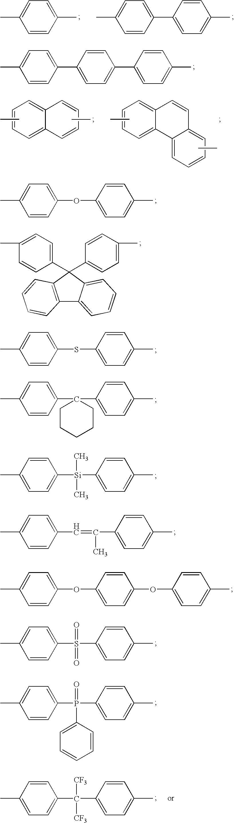
- E 1 and E 2 include one or more aromatic rings.
- E 1 and E 2 include one or more of the following moieties:
- a polymer blend in another embodiment, is provided.
- the polymer blend of this embodiment includes a first polymer and a second polymer.
- the first polymer includes the polymer segment 1 set forth above.
- the first polymer is different than the second polymer.
- the second polymer is a non-ionic polymer.
- the non-ionic polymer is a fluorine-containing polymer such as a fluoro-elastomer or fluoro-rubber.
- the fluoro-elastomer may be any elastomeric material comprising fluorine atoms.
- the fluoro-elastomer may comprise a fluoropolymer having a glass transition temperature below about 25° C. or preferably, below 0° C.
- the fluoro-elastomer may exhibit an elongation at break in a tensile mode of at least 50% or preferably at least 100% at room temperature.
- the fluoro-elastomer is generally hydrophobic and substantially free of ionic group.
- the fluoro-elastomer may be prepared by polymerizing at least one fluoro-monomer such as vinylidene fluoride, tetrafluoroethylene, hexafluoropropylene, vinylfluoride, vinylchloride, chlorotrifluoroethylene, perfluoromethylvinyl ether, and trifluoroethylene.
- the fluoro-elastomer may also be prepared by copolymerizing at least one fluoro-monomer and at least one non-fluoro-monomer such as ethylene, propylene, methyl methacrylate, ethyl acrylate, styrene and the like.
- the fluoro-elastomer may be prepared by free radical polymerization or anionic polymerization in bulk, emulsion, suspension and solution.
- fluoro-elastomers examples include poly(tetrafluoroethlyene-co-ethylene), poly(vinylidene fluoride-co-hexafluoropropylene), poly(tetrafluoroethylene-co-propylene), terpolymer of vinylidene fluoride, hexafluoropropylene and tetrafluoroethylene, and terpolymer of ethylene, tetrafluoroethylene and perfluoromethylvinylether.
- Kynar Flex 2751 is a useful copolymer of vinylidene fluoride and hexafluoropropylene with a melting temperature between about 130° C. and 140° C.
- the glass transition temperature of Kynar Flex 2751 is about ⁇ 40 to ⁇ 44° C.
- the fluoro-elastomer may further comprise a curing agent to allow crosslinking reaction after blended with a first polymer that includes a perfluorocyclobutyl moiety.
- the second polymer is a perfluorosulfonic acid polymer (PFSA).
- PFSAs are a copolymer containing a polymerization unit based on a perfluorovinyl compound represented by: CF 2 ⁇ CF—(OCF 2 CFX 1 ) m —O r —(CF 2 ) q —SO 3 H where m represents an integer of from 0 to 3, q represents an integer of from 1 to 12, r represents 0 or 1, and X 1 represents a fluorine atom or a trifluoromethyl group) and a polymerization unit based on tetrafluoroethylene.
- the second polymer is present in an amount from about 5 to about 70 weight percent of the total weight of the polymer blend. In a further refinement, the second polymer is present in an amount from about 10 to about 60 weight percent of the total weight of the polymer blend. In still another refinement, the polymer having polymer segment 1 is present in an amount from about 30 to about 95 weight percent of the total weight of the polymer blend. In still another refinement, the polymer having polymer segment 1 (i.e., the first polymer) is present in an amount from about 40 to about 90 weight percent of the total weight of the polymer blend.
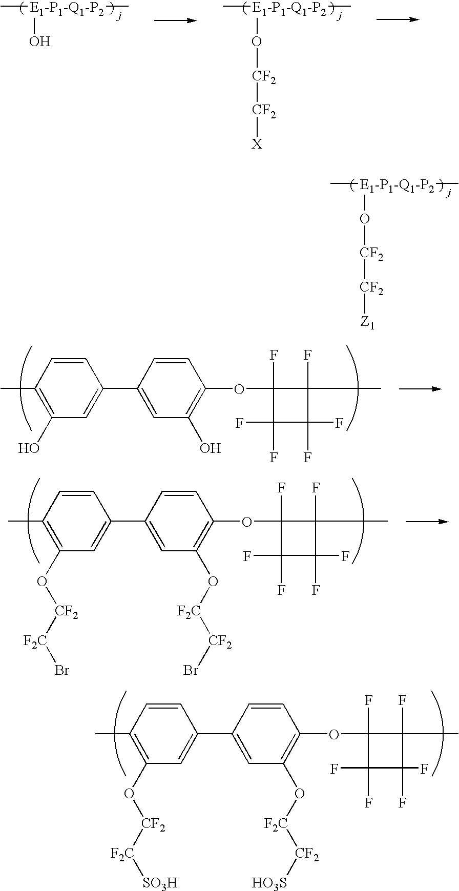
- a method for making the polymers including the polymer segment of formula 1 is provided.
- the method of this method advantageously utilizes a variation of the Ullmann reaction.
- the polymer having polymer unit 3 is halogenated to form a polymer having polymer unit 4 :
- X 2 is a halogen
- j, E 1 , P 1 , Q 1 , and P 2 are as set forth above.
- X 2 is Br or I.
- X 2 is Br.
- the polymer having polymer unit 4 is coupled as set as set forth in Scheme 1 to form the polymer having polymer unit 2 .
- groups include at least one hydroxyl that may be functionalized as set forth below:
- Table 1 provides a set of membranes used to evaluate the performance of membrane humidifier assemblies made in accordance with embodiments set forth above.
- a membrane using a standard perfluorosulfonic acid polymer membrane is used as a baseline.
- a 5 wt % solution, in N,N-dimethylacetamide is prepared using a perfluorocyclobutyl-graft-perfluorosulfonic acid (PFCB-g-PFSA) ionomer prepared from the reaction of the potassium salt of 2-(2-iodotetrafluoroethoxy)tetrafluoroethanesulfonyl fluoride, CAS#:[66137-74-4] with the aryl brominated perfluorocyclobutyl polymer (90,000 Mw) polymerized from a 16,000 Mw biphenyl perfluorocyclobutane oligomer and a hexafluoroisopropylidene-bis-trifluorovinyl ether monomer.
- PFCB-g-PFSA perfluorocyclobutyl-graft-perfluorosulfonic acid
- a blend solution is prepared by adding 3 g of a 5 wt % solution of Kynar Flex 2751 in N,N-dimethylacetamide to 7 g of the 5 wt % PFCB-g-PFSA solution.
- the 5 wt % solution is then coated on a clean sheet of extruded Teflon® at 50° C. and the ePTFE support (example Donaldson 1326) is laid-down on top of the wet layer such that the solution is able to contact the porous support.
- the ePTFE structure remains opaque and the wet-film is dried over a 15 minute period.
- the resultant single layer composite membrane film is peeled from the clean sheet of extruded Teflon® and used as a water vapor transfer membrane in a humidified, hydrogen-air fuel cell that is operated at less than 100° C.
- a 5 wt % solution, in N,N-dimethylacetamide is prepared using a perfluorocyclobutyl-graft-perfluorosulfonic acid (PFCB-g-PFSA) ionomer prepared from the reaction of the potassium salt of 2-(2-iodotetrafluoroethoxy)tetrafluoroethanesulfonyl fluoride, CAS#:[66137-74-4] with the aryl brominated perfluorocyclobutyl polymer (90,000 Mw) polymerized from a 16,000 Mw biphenyl perfluorocyclobutane oligomer and a hexafluoroisopropylidene-bis-trifluorovinyl ether monomer.
- PFCB-g-PFSA perfluorocyclobutyl-graft-perfluorosulfonic acid
- a blend solution is prepared by adding 4 g of a 5 wt % solution of Kynar Flex 2751 in N,N-dimethylacetamide to 6 g of the 5 wt % PFCB-g-PFSA solution.
- the 5 wt % solution is then coated on a clean sheet of extruded Teflon® at 50° C. and the ePTFE support (example Donaldson 1326) is laid-down on top of the wet layer such that the solution is able to contact the porous support.
- the ePTFE structure remains opaque and the wet-film is dried over a 15 minute period.
- the resultant single layer composite membrane film is peeled from the clean sheet of extruded Teflon® and used as a water vapor transfer membrane in a humidified, hydrogen-air fuel cell system that is operated at less than 100° C.
- a 5 wt % solution, in N,N-dimethylacetamide is prepared using a perfluorocyclobutyl-graft-perfluorosulfonic acid (PFCB-g-PFSA) ionomer prepared from the reaction of the potassium salt of 2-(2-iodotetrafluoroethoxy)tetrafluoroethanesulfonyl fluoride, CAS#:[66137-74-4] with the aryl brominated perfluorocyclobutyl polymer (90,000 Mw) polymerized from a 16,000 Mw biphenyl perfluorocyclobutane oligomer and a hexafluoroisopropylidene-bis-trifluorovinyl ether monomer.
- PFCB-g-PFSA perfluorocyclobutyl-graft-perfluorosulfonic acid
- a blend solution is prepared by adding 4.5 g of a 5 wt % solution of Kynar Flex 2751 in N,N-dimethylacetamide to 5.5 g of the 5 wt % PFCB-g-PFSA solution.
- the 5 wt % solution is then coated on a clean sheet of extruded Teflon® at 50° C. and the ePTFE support (example Donaldson 1326) is laid-down on top of the wet layer such that the solution is able to contact the porous support.
- the ePTFE structure remains opaque and the wet-film is dried over a 15 minute period.
- the resultant single layer composite membrane film is peeled from the clean sheet of extruded Teflon® and used as a water vapor transfer membrane in a humidified, hydrogen-air fuel cell system that is operated at less than 100° C.
- a 5 wt % solution, in N,N-dimethylacetamide is prepared using a perfluorocyclobutyl-graft-perfluorosulfonic acid (PFCB-g-PFSA) ionomer prepared from the reaction of the potassium salt of 2-(2-iodotetrafluoroethoxy)tetrafluoroethanesulfonyl fluoride, CAS#:[66137-74-4] with the aryl brominated perfluorocyclobutyl polymer (90,000 Mw) polymerized from a 16,000 Mw biphenyl perfluorocyclobutane oligomer and a hexafluoroisopropylidene-bis-trifluorovinyl ether monomer.
- PFCB-g-PFSA perfluorocyclobutyl-graft-perfluorosulfonic acid
- a blend solution is prepared by adding 3 g of a 5 wt % solution of Kynar Flex 2751 in N,N-dimethylacetamide to 7 g of the 5 wt % PFCB solution.
- the ePTFE support (example Donaldson 1326) is placed in contact with a clean sheet of extruded Teflon® at 50° C., wetted homogeneously with isopropanol and dried.
- the 5 wt % perfluorocyclobutyl ionomer blend solution is coated on the porous ePTFE support.
- the ePTFE structure remains opaque and the wet-film is dried over a 15 minute period.
- the resultant single layer composite membrane film is lifted from the clean sheet of extruded Teflon® and used as a water vapor transfer membrane in a humidified, hydrogen-air fuel cell system that is operated at less than 100° C.
- FIG. 6 provides experimental results at a common screening point for materials for water vapor transfer within a humidified, hydrogen-air fuel cell system. Grams of water transferred across the membrane are measured for a 50 cm 2 sample from a wet inlet stream of 80° C., 85% relative humidity, 10 slpm dry gas flow, and 160 kPaa to a dry inlet stream of 80° C., 0% relative humidity, 11.5 slpm dry gas flow, 80° C., and 183 kPaa. It is clear, that the humdifiers of the invention exhibit significantly improved performance compared to humidifiers using Nafion®.
Abstract
Description
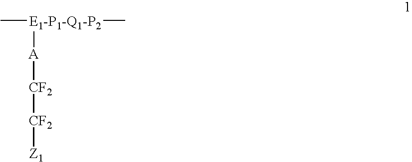
wherein:
-
- Z1 is a protogenic group such as —SO2X, —PO3H2, —COX, and the like;
- E1 is an aromatic containing moiety;
- A is absent or O or a chain extender having a carbon backbone;
- X is an —OH, a halogen, an ester, or

-
- P1, P2 are each independently absent, —O—, —S—, —SO—, —SO2—, —CO—, —NH—, NR2—, or —R3—, and
- R2 is C1-25 alkyl, C1-25 aryl, or C1-25 arylene;
- R3 is C1-25 alkylene, C1-25 perfluoroalkylene, or C1-25 arylene;
- R4 is trifluoromethyl, C1-25 alkyl, C1-25 perfluoroalkylene, C1-25 aryl, or another E1 group;
- Q1 is a fluorinated cyclobutyl moiety
ARc =W C/(W C +W L)
where Wc is a channel width and WL is a channel depth. In a variation, the channel area ratios ARc are in the range of 75-85% with a channel width Wc of between 0.5 mm and 5 mm and channel depths between 0.1 mm and 0.5 mm. Such channel area ratios ARc and channel widths Wc are chosen to maximize a membrane area utilization under the

wherein:
-
- Z1 is a protogenic group such as —SO2X, —PO3H2, —COX, and the like;
- E1 is an aromatic containing moiety;
- A is absent or oxygen (O) or a chain extender having a carbon backbone;
- X is an —OH, a halogen, an ester, or

-
- P1, P2 are each independently absent, —O—, —S—, —SO—, —SO2—, —CO—, —NH—, NR2—, or —R3—, and
- R2 is C1-25 alkyl, C1-25 aryl, or C1-25 arylene;
- R3 is C1-25 alkylene, C1-25 perfluoroalkylene, or C1-25 arylene;
- R4 is trifluoromethyl, C1-25 alkyl, C1-25 perfluoroalkylene, C1-25 aryl, or another E1 group; and
- Q1 is a fluorinated cyclobutyl moiety.
In a variation of the present embodiment,polymer segment 1 is repeated j times to form polymer block described byformula 2.
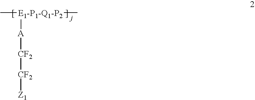
In a refinement, j is from about 1 to 10,000. In another refinement, j is from about 2 to about 100. In another refinement, j is from about 3 to about 50. In still another refinement, j is from about 4 to about 40.
E2-P3-Q2-
wherein:
-
- E2 is an aromatic containing moiety;
- P3, P4 are each independently absent, —O—, —S—, —SO—, —SO2—, —CO—, —NH—, NR2—, or —R3—, and
- R2 is C1-25 alkyl, C1-25 aryl, or C1-25 arylene;
- R3 is C1-25 alkylene, C1-25 perfluoroalkylene, or C1-25 arylene;
- R4 is trifluoromethyl, C1-25 alkyl, C1-25 perfluoroalkylene, C1-25 aryl, or another E2 group; and
- Q2 is a fluorinated cyclobutyl moiety.
In a refinement, k is from about 1 to about 10,000. In another refinement, k is from about 2 to about 100. In another refinement, k is from about 3 to about 50. In still another refinement, k is from about 4 to about 40.


where R5 is an organic group, such as an alkyl or acyl group.

a, b, c, p are independently an integer from 1 to 10. In a refinement, p is 1, a is 0, b is 0, and c is 2. In another refinement, p is 0, a is 0, b is 0 and c is 2. In another refinement, p is 1, a is 1, b is 0, and c is 2. In still another refinement, p is 1, a is 1, b is 0, and c is 2. In still another other refinement, p is 1, a is 0, b is 2, and c is 2. In yet another refinement, p is 0, a is 0, b is 0 and c is 1. In a variation, -ACF2CF2—Z1 comprises:
—CF2—CF2—O—CF2CF2—Z1.

CF2═CF—(OCF2CFX1)m—Or—(CF2)q—SO3H
where m represents an integer of from 0 to 3, q represents an integer of from 1 to 12, r represents 0 or 1, and X1 represents a fluorine atom or a trifluoromethyl group) and a polymerization unit based on tetrafluoroethylene.


| TABLE 1 | ||||
| Comparative | 25 μm PFSA baseline | |||
| Example 1 | ||||
| Example 2 | |
laid down ePTFE | ||
| 2751 | ||||
| Example 3 | |
laid down ePTFE | ||
| 2751 | ||||
| Example 4 | |
laid down ePTFE | ||
| 2751 | ||||
| Example 5 | |
cast on ePTFE | ||
| 2751 | ||||
Claims (20)


—CF2—CF2—O—CF2CF2—Z1.


Priority Applications (3)
| Application Number | Priority Date | Filing Date | Title |
|---|---|---|---|
| US12/549,904 US7972732B2 (en) | 2009-08-28 | 2009-08-28 | Perfluorocyclobutane based water vapor transfer membranes with side chain perfluorosulfonic acid moieties |
| DE102010035236A DE102010035236A1 (en) | 2009-08-28 | 2010-08-24 | Perfluorocyclobutane-based water vapor transfer membranes with side chain perfluorosulfonic acid moieties |
| CN201010267470.6A CN102005587B (en) | 2009-08-28 | 2010-08-27 | Perfluorocyclobutane Based Water Vapor Transfer Membranes with Side Chain Perfluorosulfonic Acid Moieties |
Applications Claiming Priority (1)
| Application Number | Priority Date | Filing Date | Title |
|---|---|---|---|
| US12/549,904 US7972732B2 (en) | 2009-08-28 | 2009-08-28 | Perfluorocyclobutane based water vapor transfer membranes with side chain perfluorosulfonic acid moieties |
Publications (2)
| Publication Number | Publication Date |
|---|---|
| US20110053010A1 US20110053010A1 (en) | 2011-03-03 |
| US7972732B2 true US7972732B2 (en) | 2011-07-05 |
Family
ID=43625408
Family Applications (1)
| Application Number | Title | Priority Date | Filing Date |
|---|---|---|---|
| US12/549,904 Expired - Fee Related US7972732B2 (en) | 2009-08-28 | 2009-08-28 | Perfluorocyclobutane based water vapor transfer membranes with side chain perfluorosulfonic acid moieties |
Country Status (3)
| Country | Link |
|---|---|
| US (1) | US7972732B2 (en) |
| CN (1) | CN102005587B (en) |
| DE (1) | DE102010035236A1 (en) |
Cited By (3)
| Publication number | Priority date | Publication date | Assignee | Title |
|---|---|---|---|---|
| US20140113214A1 (en) * | 2012-10-24 | 2014-04-24 | GM Global Technology Operations LLC | PFCB Nanometer Scale Fibers |
| US8919746B2 (en) | 2011-01-13 | 2014-12-30 | Dana Canada Corporation | Humidifier for fuel cell systems |
| US9735438B2 (en) | 2011-01-13 | 2017-08-15 | Dana Canada Corporation | Humidifier for fuel cell systems |
Families Citing this family (2)
| Publication number | Priority date | Publication date | Assignee | Title |
|---|---|---|---|---|
| US8709199B2 (en) | 2011-09-13 | 2014-04-29 | GM Global Technology Operations LLC | Method of preparing a water vapor transfer membrane |
| US20140080080A1 (en) * | 2012-09-14 | 2014-03-20 | GM Global Technology Operations LLC | Annealed WVT Membranes to Impart Durability and Performance |
Citations (68)
| Publication number | Priority date | Publication date | Assignee | Title |
|---|---|---|---|---|
| US5021602A (en) | 1989-06-09 | 1991-06-04 | The Dow Chemical Company | Reactive compounds containing perfluorocyclobutane rings |
| US5037917A (en) | 1989-06-09 | 1991-08-06 | The Dow Chemical Company | Perfluorocyclobutane ring-containing polymers |
| US5066746A (en) | 1989-06-09 | 1991-11-19 | The Dow Chemical Company | Perfluorocyclobutane ring-containing polymers |
| US5159037A (en) | 1989-06-09 | 1992-10-27 | The Dow Chemical Company | Perfluorocyclobutane ring-containing polymers |
| US5159038A (en) | 1989-06-09 | 1992-10-27 | Dow Chemical Company | Perfluorocyclobutane ring-containing polymers |
| US5910378A (en) | 1997-10-10 | 1999-06-08 | Minnesota Mining And Manufacturing Company | Membrane electrode assemblies |
| US6124060A (en) | 1998-05-20 | 2000-09-26 | Honda Giken Kogyo Kabushiki Kaisha | Solid polymer electrolytes |
| US6277512B1 (en) | 1999-06-18 | 2001-08-21 | 3M Innovative Properties Company | Polymer electrolyte membranes from mixed dispersions |
| US20010018144A1 (en) | 2000-02-15 | 2001-08-30 | Asahi Glass Company, Limited | Block polymer, process for producing a polymer, and polymer electrolyte fuel cell |
| US6284399B1 (en) | 1999-09-17 | 2001-09-04 | Plug Power Llc | Fuel cell system having humidification membranes |
| US20020014405A1 (en) | 2000-06-23 | 2002-02-07 | Ausimont S.P.A. | Fluorinated Ionomers |
| US6444343B1 (en) | 1996-11-18 | 2002-09-03 | University Of Southern California | Polymer electrolyte membranes for use in fuel cells |
| US20030017379A1 (en) | 2001-04-11 | 2003-01-23 | Jameel Menashi | Fuel cells and other products containing modified carbon products |
| US6523699B1 (en) | 1999-09-20 | 2003-02-25 | Honda Giken Kogyo Kabushiki Kaisha | Sulfonic acid group-containing polyvinyl alcohol, solid polymer electrolyte, composite polymer membrane, method for producing the same and electrode |
| US6559237B1 (en) | 2000-06-05 | 2003-05-06 | 3M Innovative Properties Company | Sulfonated perfluorocyclobutane ion-conducting membranes |
| WO2004051776A1 (en) | 2002-12-02 | 2004-06-17 | Sanyo Electric Co.,Ltd. | Solid polymer electrolytic film, solid polymer fuel cell employing it, and process for producing the same |
| US6783878B2 (en) | 1997-06-30 | 2004-08-31 | Ballard Power Systems Inc. | Solid polymer fuel cell system and method for humidifying and adjusting the temperature of a reactant stream |
| US20040214058A1 (en) | 2002-06-20 | 2004-10-28 | Tanaka Kikinzoku Kogyo K.K. | Fuel electrode of solid polymer electrolyte fuel cell |
| US20040214065A1 (en) | 2003-03-19 | 2004-10-28 | Nagayuki Kanaoka | Polymer electrolyte and proton-conducting membrane |
| US20040241515A1 (en) | 2003-05-28 | 2004-12-02 | Frank Brenner | Fuel cell device |
| US20050014927A1 (en) | 2003-07-16 | 2005-01-20 | Honda Motor Co., Ltd. | Sulfonated polyphosphazene derivative and method for producing the same |
| US6847518B2 (en) | 2002-12-04 | 2005-01-25 | Honda Motor Co., Ltd. | Membrane electrode assembly for polymer electrolyte fuel cell |
| US20050043487A1 (en) | 2003-08-19 | 2005-02-24 | Felix Vinci Martinez | Membranes of fluorinated ionomer blended with nonionomeric fluoropolymers for electrochemical cells |
| US20050048342A1 (en) | 2003-07-09 | 2005-03-03 | Honda Motor Co., Ltd. | Membrane electrode assembly and fuel cell |
| US6864005B2 (en) | 2000-03-08 | 2005-03-08 | Ballard Power Systems Inc. | Membrane exchange humidifier for a fuel cell |
| US20050053810A1 (en) | 2003-09-08 | 2005-03-10 | Honda Motor Co., Ltd. | Method and system for starting up fuel cell stack at subzero temperatures, and method of designing fuel cell stack |
| US20050058864A1 (en) | 2003-09-12 | 2005-03-17 | Goebel Steven G. | Nested bipolar plate for fuel cell and method |
| US20050064260A1 (en) | 2003-09-19 | 2005-03-24 | Jsr Corporation | Membrane-electrode structure for solid polymer fuel cell |
| US6875537B2 (en) | 2001-12-12 | 2005-04-05 | Honda Giken Kogyo Kabushiki Kaisha | Membrane electrode assembly for polymer electrolyte fuel cell |
| US6884536B1 (en) | 1999-11-08 | 2005-04-26 | Matsushita Electric Industrial Co., Ltd. | Polymer electrolyte fuel cell |
| US20050100770A1 (en) | 2003-11-12 | 2005-05-12 | Honda Motor Co., Ltd. | Electrolyte-electrode assembly and method for producing the same |
| US20050106440A1 (en) | 2003-11-19 | 2005-05-19 | Honda Motor Co., Ltd. | Proton conductor and method for producing the same |
| JP2005129298A (en) | 2003-10-22 | 2005-05-19 | Honda Motor Co Ltd | Forming method of electrolyte film for fuel cell |
| US20050116206A1 (en) | 2003-11-28 | 2005-06-02 | Jsr Corporation | Proton conductive composition and proton conductive membrane |
| US20050130024A1 (en) | 2003-12-10 | 2005-06-16 | Jsr Corporation | Proton conductive composition and proton conductive membrane |
| JP2005166557A (en) | 2003-12-04 | 2005-06-23 | Jsr Corp | Polymer electrolyte composite membrane, its manufacturing method and solid polymer type fuel cell using it |
| US20050143530A1 (en) | 2003-12-25 | 2005-06-30 | Honda Motor Co., Ltd. | Proton conductor and method for producing the same |
| US20050142397A1 (en) | 2003-12-24 | 2005-06-30 | Honda Motor Co., Ltd. | Membrane electrode assembly and fuel cell |
| JP2005179380A (en) | 2003-12-15 | 2005-07-07 | San Nopco Ltd | Fluorescent whiteness-enhancing agent |
| US6926984B2 (en) | 2001-01-19 | 2005-08-09 | Honda Giken Kabushiki Kaisha | Polymer electrolyte membrane, method for producing same, and membrane electrode assembly and polymer electrolyte fuel cell comprising same |
| US20050175886A1 (en) | 2000-10-12 | 2005-08-11 | Honda Giken Kogyo Kabushiki Kaisha | Active solid polymer electrolyte membrane for solid polymer electrolyte fuel cell |
| US6933068B2 (en) | 2001-01-19 | 2005-08-23 | Honda Giken Kogyo Kabushiki Kaisha | Polymer electrolyte membrane and solid polymer electrolyte fuel cell using same |
| US20050197467A1 (en) | 2004-03-03 | 2005-09-08 | Honda Motor Co., Ltd. | Proton conductor |
| US6953653B2 (en) | 2001-08-30 | 2005-10-11 | Clemson University | Fluoropolymer compositions, optical devices, and methods for fabricating optical devices |
| US20050227138A1 (en) | 2004-04-07 | 2005-10-13 | Honda Motor Co., Ltd | Polymer electrolyte fuel cell |
| US20050233181A1 (en) | 2002-06-26 | 2005-10-20 | Honda Giken Kogyo Kabushiki Kaisha | Solid high polymer type cell assembly |
| US6986962B2 (en) | 2001-07-02 | 2006-01-17 | Honda Giken Kogyo Kabushiki Kaisha | Basic polymer electrolyte fuel cell |
| US20060019147A1 (en) | 2004-07-15 | 2006-01-26 | Honda Motor Co., Ltd. | Solid polymer electrolyte fuel cell and method for manufacturing the same |
| US7001929B2 (en) | 2002-08-20 | 2006-02-21 | Jsr Corporation | Proton conductive membrane having improved thermal stability |
| US7045241B2 (en) | 2002-07-18 | 2006-05-16 | Honda Giken Kogyo Kabushiki Kaisha | Proton conductive solid polymer electrolyte and method for producing the same |
| US20060127728A1 (en) | 2004-12-15 | 2006-06-15 | JSR CORPORATION; and | Membrane-electrode assembly for fuel cell |
| US20060177719A1 (en) | 2005-02-08 | 2006-08-10 | Fuller Timothy J | Sulfonated polyelectrolyte membranes containing perfluorosulfonate ionomers |
| US20070099054A1 (en) | 2005-11-01 | 2007-05-03 | Fuller Timothy J | Sulfonated-perfluorocyclobutane polyelectrolyte membranes for fuel cells |
| WO2007052954A1 (en) | 2005-11-01 | 2007-05-10 | Lg Chem, Ltd. | Block copolymers containing perfluorocyclobutane rings and electrolyte membranes using the same |
| US20070141237A1 (en) | 2003-10-22 | 2007-06-21 | Gen Okiyama | Method for producing membrane-electrode assembly for fuel cell |
| US20070196720A1 (en) | 2006-02-21 | 2007-08-23 | Skala Glenn W | Fuel cell integrated humidification |
| US20080001313A1 (en) | 2006-06-29 | 2008-01-03 | Yan Zhang | Membrane humidifier for a fuel cell |
| US20080027152A1 (en) * | 2006-07-28 | 2008-01-31 | Gm Global Technology Operations, Inc. | Fluorinated Polymer Blocks For PEM Applications |
| US20080102335A1 (en) | 2006-10-25 | 2008-05-01 | Gm Global Technology Operations, Inc. | Thermally integrated fuel cell humidifier for rapid warm-up |
| US20080182149A1 (en) | 2007-01-31 | 2008-07-31 | Gm Global Technology Operations, Inc. | High Performance, Compact and Low Pressure Drop Spiral-Wound Fuel cell Humidifier Design |
| US20080241636A1 (en) | 2007-04-02 | 2008-10-02 | Benno Andreas-Schott | Sealed water vapor transfer unit assembly with integrated load transferring structure |
| US20090092863A1 (en) | 2007-10-08 | 2009-04-09 | Skala Glenn W | Fuel cell membrane humidifier plate design |
| JP2009249487A (en) | 2008-04-04 | 2009-10-29 | Idemitsu Kosan Co Ltd | Polymer having alicyclic ring structure and perfluoro cyclobutyl ether structure |
| US20090278083A1 (en) | 2008-05-09 | 2009-11-12 | Gm Global Technology Operations, Inc. | Polyelectrolyte membranes comprised of blends of pfsa and sulfonated pfcb polymers |
| US20090281245A1 (en) | 2008-05-09 | 2009-11-12 | Gm Global Technology Operations, Inc. | Novel proton exchange membranes for fuel cell applications |
| US20090281270A1 (en) | 2008-05-09 | 2009-11-12 | Gm Global Technology Operations, Inc. | Sulfonated-polyperfluoro-cyclobutane-polyphenlene polymers for pem fuel cell applications |
| US20090278091A1 (en) | 2008-05-09 | 2009-11-12 | Gm Global Technology Operations, Inc. | Sulfonated perfluorocyclobutane block copolymers and proton conductive polymer membranes |
| US20090281262A1 (en) | 2008-05-09 | 2009-11-12 | Gm Global Technology Operations, Inc. | Proton conductive polymer electrolytes and fuel cells |
Family Cites Families (1)
| Publication number | Priority date | Publication date | Assignee | Title |
|---|---|---|---|---|
| JP2001202975A (en) | 2000-01-19 | 2001-07-27 | Honda Motor Co Ltd | Humidifier for fuel cell |
-
2009
- 2009-08-28 US US12/549,904 patent/US7972732B2/en not_active Expired - Fee Related
-
2010
- 2010-08-24 DE DE102010035236A patent/DE102010035236A1/en not_active Withdrawn
- 2010-08-27 CN CN201010267470.6A patent/CN102005587B/en active Active
Patent Citations (72)
| Publication number | Priority date | Publication date | Assignee | Title |
|---|---|---|---|---|
| US5021602A (en) | 1989-06-09 | 1991-06-04 | The Dow Chemical Company | Reactive compounds containing perfluorocyclobutane rings |
| US5066746A (en) | 1989-06-09 | 1991-11-19 | The Dow Chemical Company | Perfluorocyclobutane ring-containing polymers |
| US5159037A (en) | 1989-06-09 | 1992-10-27 | The Dow Chemical Company | Perfluorocyclobutane ring-containing polymers |
| US5159038A (en) | 1989-06-09 | 1992-10-27 | Dow Chemical Company | Perfluorocyclobutane ring-containing polymers |
| US5037917A (en) | 1989-06-09 | 1991-08-06 | The Dow Chemical Company | Perfluorocyclobutane ring-containing polymers |
| US6444343B1 (en) | 1996-11-18 | 2002-09-03 | University Of Southern California | Polymer electrolyte membranes for use in fuel cells |
| US6783878B2 (en) | 1997-06-30 | 2004-08-31 | Ballard Power Systems Inc. | Solid polymer fuel cell system and method for humidifying and adjusting the temperature of a reactant stream |
| US5910378A (en) | 1997-10-10 | 1999-06-08 | Minnesota Mining And Manufacturing Company | Membrane electrode assemblies |
| US6183668B1 (en) | 1997-10-10 | 2001-02-06 | 3M Innovative Properties Company | Membrane electrode assemblies |
| US6124060A (en) | 1998-05-20 | 2000-09-26 | Honda Giken Kogyo Kabushiki Kaisha | Solid polymer electrolytes |
| US6277512B1 (en) | 1999-06-18 | 2001-08-21 | 3M Innovative Properties Company | Polymer electrolyte membranes from mixed dispersions |
| US6284399B1 (en) | 1999-09-17 | 2001-09-04 | Plug Power Llc | Fuel cell system having humidification membranes |
| US6523699B1 (en) | 1999-09-20 | 2003-02-25 | Honda Giken Kogyo Kabushiki Kaisha | Sulfonic acid group-containing polyvinyl alcohol, solid polymer electrolyte, composite polymer membrane, method for producing the same and electrode |
| US6884536B1 (en) | 1999-11-08 | 2005-04-26 | Matsushita Electric Industrial Co., Ltd. | Polymer electrolyte fuel cell |
| US20010018144A1 (en) | 2000-02-15 | 2001-08-30 | Asahi Glass Company, Limited | Block polymer, process for producing a polymer, and polymer electrolyte fuel cell |
| US6864005B2 (en) | 2000-03-08 | 2005-03-08 | Ballard Power Systems Inc. | Membrane exchange humidifier for a fuel cell |
| JP2003535929A (en) | 2000-06-05 | 2003-12-02 | スリーエム イノベイティブ プロパティズ カンパニー | Sulfonated perfluorocyclobutane ion conductive membrane |
| US6559237B1 (en) | 2000-06-05 | 2003-05-06 | 3M Innovative Properties Company | Sulfonated perfluorocyclobutane ion-conducting membranes |
| US20020014405A1 (en) | 2000-06-23 | 2002-02-07 | Ausimont S.P.A. | Fluorinated Ionomers |
| US20050175886A1 (en) | 2000-10-12 | 2005-08-11 | Honda Giken Kogyo Kabushiki Kaisha | Active solid polymer electrolyte membrane for solid polymer electrolyte fuel cell |
| US6926984B2 (en) | 2001-01-19 | 2005-08-09 | Honda Giken Kabushiki Kaisha | Polymer electrolyte membrane, method for producing same, and membrane electrode assembly and polymer electrolyte fuel cell comprising same |
| US6933068B2 (en) | 2001-01-19 | 2005-08-23 | Honda Giken Kogyo Kabushiki Kaisha | Polymer electrolyte membrane and solid polymer electrolyte fuel cell using same |
| US20050260474A1 (en) | 2001-01-19 | 2005-11-24 | Honda Giken Kogyo Kabushiki Kaisha | Polymer electrolyte membrane, method for producing same, and membrane electrode assembly and polymer electrolyte fuel cell comprising same |
| US20030017379A1 (en) | 2001-04-11 | 2003-01-23 | Jameel Menashi | Fuel cells and other products containing modified carbon products |
| US6986962B2 (en) | 2001-07-02 | 2006-01-17 | Honda Giken Kogyo Kabushiki Kaisha | Basic polymer electrolyte fuel cell |
| US6953653B2 (en) | 2001-08-30 | 2005-10-11 | Clemson University | Fluoropolymer compositions, optical devices, and methods for fabricating optical devices |
| US6875537B2 (en) | 2001-12-12 | 2005-04-05 | Honda Giken Kogyo Kabushiki Kaisha | Membrane electrode assembly for polymer electrolyte fuel cell |
| US20040214058A1 (en) | 2002-06-20 | 2004-10-28 | Tanaka Kikinzoku Kogyo K.K. | Fuel electrode of solid polymer electrolyte fuel cell |
| US20070042242A1 (en) | 2002-06-20 | 2007-02-22 | Tanaka Kikinzoku Kogyo K.K. | Fuel electrode of solid polymer electrolyte fuel cell |
| US20050233181A1 (en) | 2002-06-26 | 2005-10-20 | Honda Giken Kogyo Kabushiki Kaisha | Solid high polymer type cell assembly |
| US7045241B2 (en) | 2002-07-18 | 2006-05-16 | Honda Giken Kogyo Kabushiki Kaisha | Proton conductive solid polymer electrolyte and method for producing the same |
| US7001929B2 (en) | 2002-08-20 | 2006-02-21 | Jsr Corporation | Proton conductive membrane having improved thermal stability |
| WO2004051776A1 (en) | 2002-12-02 | 2004-06-17 | Sanyo Electric Co.,Ltd. | Solid polymer electrolytic film, solid polymer fuel cell employing it, and process for producing the same |
| US6847518B2 (en) | 2002-12-04 | 2005-01-25 | Honda Motor Co., Ltd. | Membrane electrode assembly for polymer electrolyte fuel cell |
| US20040214065A1 (en) | 2003-03-19 | 2004-10-28 | Nagayuki Kanaoka | Polymer electrolyte and proton-conducting membrane |
| US20040241515A1 (en) | 2003-05-28 | 2004-12-02 | Frank Brenner | Fuel cell device |
| US20050048342A1 (en) | 2003-07-09 | 2005-03-03 | Honda Motor Co., Ltd. | Membrane electrode assembly and fuel cell |
| US20050014927A1 (en) | 2003-07-16 | 2005-01-20 | Honda Motor Co., Ltd. | Sulfonated polyphosphazene derivative and method for producing the same |
| US20050043487A1 (en) | 2003-08-19 | 2005-02-24 | Felix Vinci Martinez | Membranes of fluorinated ionomer blended with nonionomeric fluoropolymers for electrochemical cells |
| US20050053810A1 (en) | 2003-09-08 | 2005-03-10 | Honda Motor Co., Ltd. | Method and system for starting up fuel cell stack at subzero temperatures, and method of designing fuel cell stack |
| US20050058864A1 (en) | 2003-09-12 | 2005-03-17 | Goebel Steven G. | Nested bipolar plate for fuel cell and method |
| US20050064260A1 (en) | 2003-09-19 | 2005-03-24 | Jsr Corporation | Membrane-electrode structure for solid polymer fuel cell |
| US20070141237A1 (en) | 2003-10-22 | 2007-06-21 | Gen Okiyama | Method for producing membrane-electrode assembly for fuel cell |
| JP2005129298A (en) | 2003-10-22 | 2005-05-19 | Honda Motor Co Ltd | Forming method of electrolyte film for fuel cell |
| US20050100770A1 (en) | 2003-11-12 | 2005-05-12 | Honda Motor Co., Ltd. | Electrolyte-electrode assembly and method for producing the same |
| US20050106440A1 (en) | 2003-11-19 | 2005-05-19 | Honda Motor Co., Ltd. | Proton conductor and method for producing the same |
| US20050116206A1 (en) | 2003-11-28 | 2005-06-02 | Jsr Corporation | Proton conductive composition and proton conductive membrane |
| JP2005166557A (en) | 2003-12-04 | 2005-06-23 | Jsr Corp | Polymer electrolyte composite membrane, its manufacturing method and solid polymer type fuel cell using it |
| US20050130024A1 (en) | 2003-12-10 | 2005-06-16 | Jsr Corporation | Proton conductive composition and proton conductive membrane |
| JP2005179380A (en) | 2003-12-15 | 2005-07-07 | San Nopco Ltd | Fluorescent whiteness-enhancing agent |
| US20050142397A1 (en) | 2003-12-24 | 2005-06-30 | Honda Motor Co., Ltd. | Membrane electrode assembly and fuel cell |
| US20050143530A1 (en) | 2003-12-25 | 2005-06-30 | Honda Motor Co., Ltd. | Proton conductor and method for producing the same |
| US20050197467A1 (en) | 2004-03-03 | 2005-09-08 | Honda Motor Co., Ltd. | Proton conductor |
| US20050227138A1 (en) | 2004-04-07 | 2005-10-13 | Honda Motor Co., Ltd | Polymer electrolyte fuel cell |
| US20060019147A1 (en) | 2004-07-15 | 2006-01-26 | Honda Motor Co., Ltd. | Solid polymer electrolyte fuel cell and method for manufacturing the same |
| US20060127728A1 (en) | 2004-12-15 | 2006-06-15 | JSR CORPORATION; and | Membrane-electrode assembly for fuel cell |
| US20060177719A1 (en) | 2005-02-08 | 2006-08-10 | Fuller Timothy J | Sulfonated polyelectrolyte membranes containing perfluorosulfonate ionomers |
| US20070099054A1 (en) | 2005-11-01 | 2007-05-03 | Fuller Timothy J | Sulfonated-perfluorocyclobutane polyelectrolyte membranes for fuel cells |
| WO2007052954A1 (en) | 2005-11-01 | 2007-05-10 | Lg Chem, Ltd. | Block copolymers containing perfluorocyclobutane rings and electrolyte membranes using the same |
| US20070196720A1 (en) | 2006-02-21 | 2007-08-23 | Skala Glenn W | Fuel cell integrated humidification |
| US20080001313A1 (en) | 2006-06-29 | 2008-01-03 | Yan Zhang | Membrane humidifier for a fuel cell |
| US20080027152A1 (en) * | 2006-07-28 | 2008-01-31 | Gm Global Technology Operations, Inc. | Fluorinated Polymer Blocks For PEM Applications |
| US20080102335A1 (en) | 2006-10-25 | 2008-05-01 | Gm Global Technology Operations, Inc. | Thermally integrated fuel cell humidifier for rapid warm-up |
| US20080182149A1 (en) | 2007-01-31 | 2008-07-31 | Gm Global Technology Operations, Inc. | High Performance, Compact and Low Pressure Drop Spiral-Wound Fuel cell Humidifier Design |
| US20080241636A1 (en) | 2007-04-02 | 2008-10-02 | Benno Andreas-Schott | Sealed water vapor transfer unit assembly with integrated load transferring structure |
| US20090092863A1 (en) | 2007-10-08 | 2009-04-09 | Skala Glenn W | Fuel cell membrane humidifier plate design |
| JP2009249487A (en) | 2008-04-04 | 2009-10-29 | Idemitsu Kosan Co Ltd | Polymer having alicyclic ring structure and perfluoro cyclobutyl ether structure |
| US20090278083A1 (en) | 2008-05-09 | 2009-11-12 | Gm Global Technology Operations, Inc. | Polyelectrolyte membranes comprised of blends of pfsa and sulfonated pfcb polymers |
| US20090281245A1 (en) | 2008-05-09 | 2009-11-12 | Gm Global Technology Operations, Inc. | Novel proton exchange membranes for fuel cell applications |
| US20090281270A1 (en) | 2008-05-09 | 2009-11-12 | Gm Global Technology Operations, Inc. | Sulfonated-polyperfluoro-cyclobutane-polyphenlene polymers for pem fuel cell applications |
| US20090278091A1 (en) | 2008-05-09 | 2009-11-12 | Gm Global Technology Operations, Inc. | Sulfonated perfluorocyclobutane block copolymers and proton conductive polymer membranes |
| US20090281262A1 (en) | 2008-05-09 | 2009-11-12 | Gm Global Technology Operations, Inc. | Proton conductive polymer electrolytes and fuel cells |
Non-Patent Citations (8)
| Title |
|---|
| "Fluorel Technical Data Sheets," MatWeb Material Property Data website, http://www.matweb.com/search/GetMatIsByTradename.aspx?navletter=F&tn=Fluorel%E2%84%A2, copyright 1996-2010. |
| Ford, L.A. et al., "New Aromatic Perfluorovinyl Ether Monomers Containing the Sulfonimide Acid Functionality," Polymeric Materials Science & Eng., v. 83, 2000, pp. 10-11. |
| Nafion perfluorinated resin, Sigma-Aldrich Online Catalog, http://www.sigmaaldrich.com/catalog/ProductDetail.do?lang=en&N4=495786|ALDRICH&N5=SEARCH-CONCAT-PNO|BRAND-KEY&F=SPEC, copyright 2010. |
| Smith, D.W. et al., "Perfluorocyclobutane (PFCB) polyaryl ethers: versatile coatings material," J. of Fluorine Chem., v. 104, pp. 109-117 (2000). |
| Smith, D.W. et al., "Perfluorocyclobutane Aromatic Polyethers. Synthesis and Characterization of New Siloxane-Containing Fluoropolymers," Macromolecules 1996, v. 29, pp. 852-860. |
| Souzy, R. et al., "Functional fluoropolymers for fuel cell membranes," Prog. Polm. Sci. 30, 2005, pp. 644-687. |
| Souzy, R. et al., "Functional fluoropolymers for fuel cell membranes," Solid State Ionics, v. 176, pp. 2839-2848 (2005). |
| Souzy, R. et al., "Synthesis and (co)polymerization of monofluoro, difluoro, trifluorostyrene and ((trifluorovinyl)oxy) benzene," Prog. Polm. Sci. 29 (2004), pp. 75-106. |
Cited By (6)
| Publication number | Priority date | Publication date | Assignee | Title |
|---|---|---|---|---|
| US8919746B2 (en) | 2011-01-13 | 2014-12-30 | Dana Canada Corporation | Humidifier for fuel cell systems |
| US9735438B2 (en) | 2011-01-13 | 2017-08-15 | Dana Canada Corporation | Humidifier for fuel cell systems |
| US10418651B2 (en) | 2011-01-13 | 2019-09-17 | Dana Canada Corporation | Humidifier for fuel cell systems |
| US20140113214A1 (en) * | 2012-10-24 | 2014-04-24 | GM Global Technology Operations LLC | PFCB Nanometer Scale Fibers |
| US9163337B2 (en) * | 2012-10-24 | 2015-10-20 | GM Global Technology Operations LLC | PFCB nanometer scale fibers |
| US9911982B2 (en) | 2012-10-24 | 2018-03-06 | GM Global Technology Operations LLC | PFCB nanometer scale fibers |
Also Published As
| Publication number | Publication date |
|---|---|
| US20110053010A1 (en) | 2011-03-03 |
| CN102005587B (en) | 2014-10-01 |
| CN102005587A (en) | 2011-04-06 |
| DE102010035236A1 (en) | 2011-04-21 |
Similar Documents
| Publication | Publication Date | Title |
|---|---|---|
| US8058352B2 (en) | Perfluorocyclobutane based water vapor transfer membranes | |
| US20110053008A1 (en) | Water vapor transfer membrane and paper integrated assembly | |
| US7745032B2 (en) | Fuel cell with humidifier | |
| US7972732B2 (en) | Perfluorocyclobutane based water vapor transfer membranes with side chain perfluorosulfonic acid moieties | |
| US20150171454A1 (en) | Membrane with laminated structure and orientation controlled nanofiber reinforcement additives for fuel cells | |
| US20120122011A1 (en) | Nano-Fibers for Electrical Power Generation | |
| US8354201B2 (en) | Fuel cell with spatially non-homogeneous ionic membrane | |
| US20110053009A1 (en) | Customized water vapor transfer membrane layered structure | |
| US20130022894A1 (en) | ePTFE-Supported Polyelectrolyte Membranes Made with Ionomer-Kynar Blends | |
| US20130084516A1 (en) | Poly(Methyl Methacrylate) Additive to Polyelectrolyte Membrane | |
| US20110165497A1 (en) | Method for Mitigating Fuel Cell Chemical Degradation | |
| US9631105B2 (en) | PPS electrode reinforcing material/crack mitigant | |
| US20180145357A1 (en) | Mitigation strategies for enhanced durability of pfsa-based sheet style water vapor transfer devices | |
| US10020526B2 (en) | Reverse osmosis membranes made with PFSA ionomer and ePTFE | |
| US20140080031A1 (en) | Dual Layered ePTFE Polyelectrolyte Membranes | |
| CN101659776A (en) | Polyelectrolyte film of blend including pfsa and sulfonated pfcb polymers | |
| US20110159404A1 (en) | Polyolefin Support to Prevent Dielectric Breakdown in PEMS | |
| US20110159405A1 (en) | Hydrophilic Polyelectrolyte Membranes Containing Poly(Vinyl Acetate) and Poly(Vinyl Alcohol) | |
| US9040209B2 (en) | Multi-layer polyelectrolyte membranes | |
| JP2005108550A (en) | Catalyst film for solid polymer fuel cells, its manufacturing method and fuel cell using the same | |
| US8044146B1 (en) | Combination of main-chain and side-chain sulfonation of PFCB-6F high-temperature fuel cell membranes | |
| US20170331121A1 (en) | Porous polyolefin supports for water vapor transfer membranes for humidifiers | |
| US20140080080A1 (en) | Annealed WVT Membranes to Impart Durability and Performance | |
| US20140045094A1 (en) | PPS Membrane Reinforcing Material | |
| JP2019114537A (en) | Fuel cell system and method |
Legal Events
| Date | Code | Title | Description |
|---|---|---|---|
| AS | Assignment |
Owner name: GM GLOBAL TECHNOLOGY OPERATIONS, INC., MICHIGAN Free format text: ASSIGNMENT OF ASSIGNORS INTEREST;ASSIGNORS:MACKINNON, SEAN M.;FULLER, TIMOTHY J.;BRENNER, ANNETTE M.;REEL/FRAME:023182/0001 Effective date: 20090827 |
|
| AS | Assignment |
Owner name: UNITED STATES DEPARTMENT OF THE TREASURY, DISTRICT Free format text: SECURITY AGREEMENT;ASSIGNOR:GM GLOBAL TECHNOLOGY OPERATIONS, INC.;REEL/FRAME:023989/0155 Effective date: 20090710 Owner name: UAW RETIREE MEDICAL BENEFITS TRUST, MICHIGAN Free format text: SECURITY AGREEMENT;ASSIGNOR:GM GLOBAL TECHNOLOGY OPERATIONS, INC.;REEL/FRAME:023990/0001 Effective date: 20090710 |
|
| AS | Assignment |
Owner name: GM GLOBAL TECHNOLOGY OPERATIONS, INC., MICHIGAN Free format text: RELEASE BY SECURED PARTY;ASSIGNOR:UNITED STATES DEPARTMENT OF THE TREASURY;REEL/FRAME:025246/0234 Effective date: 20100420 |
|
| AS | Assignment |
Owner name: GM GLOBAL TECHNOLOGY OPERATIONS, INC., MICHIGAN Free format text: RELEASE BY SECURED PARTY;ASSIGNOR:UAW RETIREE MEDICAL BENEFITS TRUST;REEL/FRAME:025315/0091 Effective date: 20101026 |
|
| AS | Assignment |
Owner name: WILMINGTON TRUST COMPANY, DELAWARE Free format text: SECURITY AGREEMENT;ASSIGNOR:GM GLOBAL TECHNOLOGY OPERATIONS, INC.;REEL/FRAME:025324/0555 Effective date: 20101027 |
|
| FEPP | Fee payment procedure |
Free format text: PAYOR NUMBER ASSIGNED (ORIGINAL EVENT CODE: ASPN); ENTITY STATUS OF PATENT OWNER: LARGE ENTITY |
|
| AS | Assignment |
Owner name: GM GLOBAL TECHNOLOGY OPERATIONS LLC, MICHIGAN Free format text: CHANGE OF NAME;ASSIGNOR:GM GLOBAL TECHNOLOGY OPERATIONS, INC.;REEL/FRAME:025781/0299 Effective date: 20101202 |
|
| STCF | Information on status: patent grant |
Free format text: PATENTED CASE |
|
| AS | Assignment |
Owner name: GM GLOBAL TECHNOLOGY OPERATIONS LLC, MICHIGAN Free format text: RELEASE BY SECURED PARTY;ASSIGNOR:WILMINGTON TRUST COMPANY;REEL/FRAME:034185/0789 Effective date: 20141017 |
|
| FPAY | Fee payment |
Year of fee payment: 4 |
|
| MAFP | Maintenance fee payment |
Free format text: PAYMENT OF MAINTENANCE FEE, 8TH YEAR, LARGE ENTITY (ORIGINAL EVENT CODE: M1552); ENTITY STATUS OF PATENT OWNER: LARGE ENTITY Year of fee payment: 8 |
|
| FEPP | Fee payment procedure |
Free format text: MAINTENANCE FEE REMINDER MAILED (ORIGINAL EVENT CODE: REM.); ENTITY STATUS OF PATENT OWNER: LARGE ENTITY |
|
| LAPS | Lapse for failure to pay maintenance fees |
Free format text: PATENT EXPIRED FOR FAILURE TO PAY MAINTENANCE FEES (ORIGINAL EVENT CODE: EXP.); ENTITY STATUS OF PATENT OWNER: LARGE ENTITY |
|
| STCH | Information on status: patent discontinuation |
Free format text: PATENT EXPIRED DUE TO NONPAYMENT OF MAINTENANCE FEES UNDER 37 CFR 1.362 |
|
| FP | Lapsed due to failure to pay maintenance fee |
Effective date: 20230705 |