US8002995B2 - Fluid analytical device - Google Patents
Fluid analytical device Download PDFInfo
- Publication number
- US8002995B2 US8002995B2 US12/060,682 US6068208A US8002995B2 US 8002995 B2 US8002995 B2 US 8002995B2 US 6068208 A US6068208 A US 6068208A US 8002995 B2 US8002995 B2 US 8002995B2
- Authority
- US
- United States
- Prior art keywords
- fluid
- area
- reservoir
- analytical device
- pile
- Prior art date
- Legal status (The legal status is an assumption and is not a legal conclusion. Google has not performed a legal analysis and makes no representation as to the accuracy of the status listed.)
- Active, expires
Links
Images


Classifications
-
- G—PHYSICS
- G01—MEASURING; TESTING
- G01N—INVESTIGATING OR ANALYSING MATERIALS BY DETERMINING THEIR CHEMICAL OR PHYSICAL PROPERTIES
- G01N33/00—Investigating or analysing materials by specific methods not covered by groups G01N1/00 - G01N31/00
- G01N33/48—Biological material, e.g. blood, urine; Haemocytometers
- G01N33/483—Physical analysis of biological material
- G01N33/487—Physical analysis of biological material of liquid biological material
- G01N33/49—Blood
- G01N33/491—Blood by separating the blood components
Definitions
- the invention relates to a fluid analytical device, and more particularly to a fluid analytical device for separating constituents of blood.
- U.S. Pat. No. 6,548,788 disclose a fluid analytical device with a micro-valve disposed on a body to stop flow.
- a micro-valve is manufactured by a micro manufacturing process, and cannot be formed by injection molding, thus, increasing costs.
- a fluid analytical device comprises a body, a reservoir, an inlet channel and a separation unit.
- the reservoir is formed on the body.
- the inlet channel is formed on the body connected to the reservoir.
- the separation unit is formed on the body connected to the inlet channel, which comprises a pile area, a collecting area and a spacer.
- the collecting area is located between the pile area and the reservoir.
- the spacer is formed between the pile area and the collecting area.
- the fluid analytical device of the invention quickly separates fluid with a simpler structure and lower cost.
- FIG. 1 a shows a fluid analytical device of a first embodiment of the invention
- FIG. 1 b is an enlarged view of portion A of FIG. 1 a;
- FIGS. 2 a - 2 c show fluid separation process of the first embodiment of the invention
- FIG. 2 d is an enlarge view of portion B of FIG. 2 c;
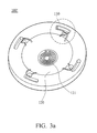
- FIG. 3 a shows a fluid analytical device of a modified example of the first embodiment
- FIG. 3 b is an enlarge view of portion C of FIG. 3 a;
- FIGS. 4 a and 4 b show a fluid analytical device of a second embodiment of the invention comprising a first body and a second body;
- FIGS. 5 a - 5 c show liquid separation process of the fluid analytical device.
- FIG. 1 a shows a fluid analytical device 100 of a first embodiment of the invention, comprising a body 110 , a reservoir 120 , separation units 130 , inlet channels 140 and exhaust channels 150 .
- the body 110 is circular, comprising a first surface 111 .
- the reservoir 120 is circular formed in a center of the body 110 .
- the separation units 130 are near an edge of the body 110 , and surround the reservoir 120 equidistantly.
- the inlet channels 140 are formed on the body 110 connecting the reservoir 120 and the separation unit 130 .
- the exhaust channels 150 are formed on the body 110 connecting the reservoir 120 and the separation units 130 .
- FIG. 1 b is an enlarged view of portion A of FIG. 1 a .
- Each separation 130 comprises a collecting area 131 , a pile area 132 and a spacer 133 .
- the collecting area 131 is located between the pile area 132 and the reservoir 120 .
- the spacer 133 is located between the collecting area 131 and the pile area 132 .
- the volume of the collecting area 131 is smaller than the volume of the pile area 132 .
- a volume ratio between the pile area 132 and the collecting area 131 is between 1:1 and 2:1.
- a ratio between a depth d of the spacer 133 and a depth of the collecting area is about between 1 ⁇ 3 and 1 ⁇ 6.
- the width W 2 of the pile area 132 along a periphery direction is greater than the width W 1 of the collecting area 131 along the periphery direction.
- the inlet channel 140 connects the separation unit 130 in a location above the spacer 133 .
- the exhaust channel 150 connects the collecting area 131 and the reservoir 120 .
- FIGS. 2 a - 2 c show fluid separation process of the first embodiment of the invention.
- fluid (blood) 10 is infused in the center of the reservoir 120 .
- the fluid analytical device 100 is rotated counterclockwise with respect to the reservoir 120 to move the fluid (blood) 10 into the separation units 130 by centrifugal force.
- FIG. 2 d is an enlarge view of portion B of FIG. 2 c , wherein the fluid (blood) 10 has been separated, a first fluid constituent (blood cells) 11 is gathered in the pile area 132 , and a second fluid constituent (plasma) 12 is collected in the collecting area 131 .
- FIG. 3 a shows a fluid analytical device 100 ′ of a modified example of the first embodiment, wherein the reservoir 120 further comprises a spiral groove 121 formed on a bottom thereof for defining the quantity of the fluid 10 .
- FIG. 3 b is an enlarge view of portion C of FIG. 3 a , wherein a plurality of guiding grooves 134 are formed on the top of the spacer 133 .
- the guiding grooves 134 guide the first fluid constituent (blood cells) to the pile area 132 by capillarity.
- FIGS. 4 a and 4 b show a fluid analytical device 200 of a second embodiment of the invention comprising a first body 210 and a second body 220 .
- the first body 210 comprises a spiral groove 211 and a first drain 212 .
- the first drain 212 connects a bottom of the spiral groove 211 passing through the first body 210 .
- the second body 220 comprises a first separation room 221 , a second drain 222 , collecting wells 223 and capillaries 224 .
- the first separation room 221 connects the first drain 222 .
- the second drain 222 connects to the first separation room 221 .
- the second drain 222 is ring shaped.
- the capillaries 224 connect the collecting well 223 and the second drain 222 .
- the first body 210 further comprises a first exhaust drain 231 , a second exhaust drain 232 and a third exhaust drain 233 .
- the first exhaust drain 231 connects an upper portion of the spiral groove 211 and the first separation room 221 .
- the second exhaust groove 232 is ring shaped and is connected to the collecting well 223 .
- the second body 220 further comprises a waste well 240 .
- the waste liquid well 240 connects the second drain 222 and the third exhaust groove 233 .
- FIGS. 5 a - 5 c show liquid separation process of the fluid analytical device 200 .
- fluid (blood) 10 is infused in the spiral groove 211 .
- the fluid analytical device 200 is rotated in a first direction (clockwise) under a first speed, wherein the fluid 10 enters the first separation room 221 , and the first fluid constituent (blood cells) 11 is separated from the second fluid constituent (plasma) 12 in the first separation room 221 .
- the fluid analytical device 200 is rotated in a second direction (counter clockwise) under a second speed, wherein the second fluid constituent (plasma) 12 flows from the first separation room 221 , passing the second drain 222 and the capillaries 224 , and enters the second separation room 223 .
- Superfluous second fluid constituent (plasma) 12 enters the waste liquid room 240 , and the first fluid constituent (blood cells) 11 stays in the first separation room 221 .
- the first speed is greater than the second speed.
- the fluid analytical device of the invention quickly separates fluid with a simpler structure and lower cost.
Abstract
Description
Claims (11)
Applications Claiming Priority (3)
| Application Number | Priority Date | Filing Date | Title |
|---|---|---|---|
| TW96141349A | 2007-11-02 | ||
| TW096141349A TWI362491B (en) | 2007-11-02 | 2007-11-02 | Fluid analytical device and fluid analytical method thereof |
| TWTW96141349 | 2007-11-02 |
Publications (2)
| Publication Number | Publication Date |
|---|---|
| US20090114608A1 US20090114608A1 (en) | 2009-05-07 |
| US8002995B2 true US8002995B2 (en) | 2011-08-23 |
Family
ID=40587051
Family Applications (1)
| Application Number | Title | Priority Date | Filing Date |
|---|---|---|---|
| US12/060,682 Active 2028-08-05 US8002995B2 (en) | 2007-11-02 | 2008-04-01 | Fluid analytical device |
Country Status (2)
| Country | Link |
|---|---|
| US (1) | US8002995B2 (en) |
| TW (1) | TWI362491B (en) |
Families Citing this family (6)
| Publication number | Priority date | Publication date | Assignee | Title |
|---|---|---|---|---|
| JP5505041B2 (en) * | 2010-03-31 | 2014-05-28 | 凸版印刷株式会社 | Biochemical reaction chip and manufacturing method thereof |
| US9562540B2 (en) * | 2011-09-29 | 2017-02-07 | Protectlife International Biomedical Inc. | Centrifugal rotor |
| CN203432978U (en) * | 2011-09-30 | 2014-02-12 | 保生国际生医股份有限公司 | Centrifugal turnplate |
| TWI513510B (en) * | 2012-08-09 | 2015-12-21 | Nat Univ Tsing Hua | Centrifugal particle separation and detection device |
| JP6349721B2 (en) * | 2013-12-24 | 2018-07-04 | 凸版印刷株式会社 | Sample analysis chip |
| CN114247489B (en) * | 2021-12-10 | 2022-08-26 | 广州国家实验室 | Microfluidic chip and exosome extraction method |
Citations (18)
| Publication number | Priority date | Publication date | Assignee | Title |
|---|---|---|---|---|
| US3873217A (en) * | 1973-07-24 | 1975-03-25 | Atomic Energy Commission | Simplified rotor for fast analyzer of rotary cuvette type |
| US4154793A (en) * | 1977-08-18 | 1979-05-15 | Jean Guigan | Device for conditioning a sample of liquid for analyzing |
| US5061381A (en) | 1990-06-04 | 1991-10-29 | Abaxis, Inc. | Apparatus and method for separating cells from biological fluids |
| US5089417A (en) | 1987-07-01 | 1992-02-18 | Miles Inc. | Fluid separation and processing device |
| US5472603A (en) * | 1992-04-02 | 1995-12-05 | Abaxis, Inc. | Analytical rotor with dye mixing chamber |
| US5916522A (en) | 1997-08-07 | 1999-06-29 | Careside, Inc. | Electrochemical analytical cartridge |
| US6319469B1 (en) * | 1995-12-18 | 2001-11-20 | Silicon Valley Bank | Devices and methods for using centripetal acceleration to drive fluid movement in a microfluidics system |
| US6527432B2 (en) * | 2000-05-15 | 2003-03-04 | Tecan Trading Ag | Bidirectional flow centrifugal microfluidic devices |
| US6548788B2 (en) | 1997-05-23 | 2003-04-15 | Tecan Trading Ag | Devices and methods for using centripetal acceleration to drive fluid movement in a microfluidics system |
| US20030166265A1 (en) * | 2002-02-26 | 2003-09-04 | Pugia Michael J. | Method and apparatus for precise transfer and manipulation of fluids by centrifugal and/or capillary forces |
| US20030219713A1 (en) * | 2001-11-20 | 2003-11-27 | Valencia Ramoncito Magpantay | Optical bio-discs and fluidic circuits for analysis of cells and methods relating thereto |
| TWI243705B (en) | 2004-12-22 | 2005-11-21 | Ind Tech Res Inst | Fluid analytical device |
| US7022286B2 (en) * | 1998-07-20 | 2006-04-04 | Lifescan, Inc. | Fluidic device for medical diagnostics |
| US7026131B2 (en) | 2000-11-17 | 2006-04-11 | Nagaoka & Co., Ltd. | Methods and apparatus for blood typing with optical bio-discs |
| US7033747B2 (en) | 2001-04-11 | 2006-04-25 | Nagaoka & Co., Ltd | Multi-parameter assays including analysis discs and methods relating thereto |
| US20060144802A1 (en) * | 2004-12-28 | 2006-07-06 | Matsushita Electric Industrial Co., Ltd. | Testing device and blood mixing and diluting method |
| US20110014094A1 (en) * | 2009-07-20 | 2011-01-20 | Samsung Electronics Co., Ltd. | Disk type microfluidic device and blood testing apparatus using the same |
| US7914753B2 (en) * | 2008-05-28 | 2011-03-29 | Industrial Technology Research Institute | Analytical system, and analytical method and flow structure thereof |
-
2007
- 2007-11-02 TW TW096141349A patent/TWI362491B/en active
-
2008
- 2008-04-01 US US12/060,682 patent/US8002995B2/en active Active
Patent Citations (19)
| Publication number | Priority date | Publication date | Assignee | Title |
|---|---|---|---|---|
| US3873217A (en) * | 1973-07-24 | 1975-03-25 | Atomic Energy Commission | Simplified rotor for fast analyzer of rotary cuvette type |
| US4154793A (en) * | 1977-08-18 | 1979-05-15 | Jean Guigan | Device for conditioning a sample of liquid for analyzing |
| US5089417A (en) | 1987-07-01 | 1992-02-18 | Miles Inc. | Fluid separation and processing device |
| US5061381A (en) | 1990-06-04 | 1991-10-29 | Abaxis, Inc. | Apparatus and method for separating cells from biological fluids |
| US5472603A (en) * | 1992-04-02 | 1995-12-05 | Abaxis, Inc. | Analytical rotor with dye mixing chamber |
| US6319469B1 (en) * | 1995-12-18 | 2001-11-20 | Silicon Valley Bank | Devices and methods for using centripetal acceleration to drive fluid movement in a microfluidics system |
| US6548788B2 (en) | 1997-05-23 | 2003-04-15 | Tecan Trading Ag | Devices and methods for using centripetal acceleration to drive fluid movement in a microfluidics system |
| US5916522A (en) | 1997-08-07 | 1999-06-29 | Careside, Inc. | Electrochemical analytical cartridge |
| US7022286B2 (en) * | 1998-07-20 | 2006-04-04 | Lifescan, Inc. | Fluidic device for medical diagnostics |
| US6527432B2 (en) * | 2000-05-15 | 2003-03-04 | Tecan Trading Ag | Bidirectional flow centrifugal microfluidic devices |
| US7026131B2 (en) | 2000-11-17 | 2006-04-11 | Nagaoka & Co., Ltd. | Methods and apparatus for blood typing with optical bio-discs |
| US7033747B2 (en) | 2001-04-11 | 2006-04-25 | Nagaoka & Co., Ltd | Multi-parameter assays including analysis discs and methods relating thereto |
| US20030219713A1 (en) * | 2001-11-20 | 2003-11-27 | Valencia Ramoncito Magpantay | Optical bio-discs and fluidic circuits for analysis of cells and methods relating thereto |
| US20030166265A1 (en) * | 2002-02-26 | 2003-09-04 | Pugia Michael J. | Method and apparatus for precise transfer and manipulation of fluids by centrifugal and/or capillary forces |
| TWI243705B (en) | 2004-12-22 | 2005-11-21 | Ind Tech Res Inst | Fluid analytical device |
| US20060133958A1 (en) | 2004-12-22 | 2006-06-22 | Wen-Pin Hsieh | Fluid analytical devices |
| US20060144802A1 (en) * | 2004-12-28 | 2006-07-06 | Matsushita Electric Industrial Co., Ltd. | Testing device and blood mixing and diluting method |
| US7914753B2 (en) * | 2008-05-28 | 2011-03-29 | Industrial Technology Research Institute | Analytical system, and analytical method and flow structure thereof |
| US20110014094A1 (en) * | 2009-07-20 | 2011-01-20 | Samsung Electronics Co., Ltd. | Disk type microfluidic device and blood testing apparatus using the same |
Non-Patent Citations (1)
| Title |
|---|
| Taiwan Patent Office, Office Action-Notice of Allowance, Patent Application Serial No. 096141349, Apr. 13, 2011, Taiwan. |
Also Published As
| Publication number | Publication date |
|---|---|
| US20090114608A1 (en) | 2009-05-07 |
| TWI362491B (en) | 2012-04-21 |
| TW200921102A (en) | 2009-05-16 |
Similar Documents
| Publication | Publication Date | Title |
|---|---|---|
| US8002995B2 (en) | Fluid analytical device | |
| CN107225006B (en) | More flux micro-fluidic chips based on the flowing of active control liquid | |
| KR100843339B1 (en) | Serum separator using microchannel for separating serum from whole blood and the method of separating serum by the same | |
| US7320776B2 (en) | Fluid analytical devices | |
| RU2008136841A (en) | CENTRIFUGAL SEPARATOR | |
| JP4752546B2 (en) | Centrifuge device and centrifuge method | |
| SE1250403A1 (en) | Tapered disc elements for a rotor for centrifugal separators as well as rotors containing such disc elements | |
| BR112019007614B1 (en) | SEPARATOR DISC FOR A CENTRIFUGAL SEPARATOR, STACK OF SEPARATION DISKS, CENTRIFUGAL SEPARATOR, AND METHOD FOR SEPARATING AT LEAST TWO COMPONENTS FROM A FLUID MIXTURE WHICH ARE OF DIFFERENT DENSITIES | |
| KR102021860B1 (en) | Dust collector and cleaner having the same | |
| WO2022068648A1 (en) | Microfluidic chip cartridge | |
| CN111330660B (en) | Centrifugal high-flux micro-droplet preparation chip | |
| US10919040B2 (en) | Method for sample separation and collection | |
| US20140193857A1 (en) | Centrifuge tube droplet generator | |
| CN210186616U (en) | Gas-liquid separator | |
| CN108251297B (en) | Three-dimensional microflow chip for driving deterministic lateral displacement based on centrifugal force and Euler force | |
| US11612889B2 (en) | Fluidic cavities for on-chip layering and sealing of separation arrays | |
| KR101575488B1 (en) | Micro fluid centrifuge for separation of particle | |
| KR101190035B1 (en) | Blood Plasma Separation Chip with Radial Filter | |
| KR102126826B1 (en) | Air intake apparatus | |
| KR101207545B1 (en) | Device for separating micro particles and method of separating micro particles | |
| KR101700228B1 (en) | Cell separation chip and its separaion method of cell | |
| JP5303803B2 (en) | Microfluidic device | |
| CN101450336B (en) | Fluid separation method and device | |
| US20240116050A1 (en) | Microfluidic bubble trap | |
| CN109488277A (en) | It is layered cage and sieves integrated cyclone degasser |
Legal Events
| Date | Code | Title | Description |
|---|---|---|---|
| AS | Assignment |
Owner name: INDUSTRIAL TECHNOLOGY RESEARCH INSTITUTE, TAIWAN Free format text: ASSIGNMENT OF ASSIGNORS INTEREST;ASSIGNORS:TSAI, CHUNG-HSIEN;CHUNG, CHENG-SHIU;HSIEH, WEN-PIN;REEL/FRAME:020747/0804;SIGNING DATES FROM 20080304 TO 20080316 Owner name: INDUSTRIAL TECHNOLOGY RESEARCH INSTITUTE, TAIWAN Free format text: ASSIGNMENT OF ASSIGNORS INTEREST;ASSIGNORS:TSAI, CHUNG-HSIEN;CHUNG, CHENG-SHIU;HSIEH, WEN-PIN;SIGNING DATES FROM 20080304 TO 20080316;REEL/FRAME:020747/0804 |
|
| STCF | Information on status: patent grant |
Free format text: PATENTED CASE |
|
| FPAY | Fee payment |
Year of fee payment: 4 |
|
| MAFP | Maintenance fee payment |
Free format text: PAYMENT OF MAINTENANCE FEE, 8TH YEAR, LARGE ENTITY (ORIGINAL EVENT CODE: M1552); ENTITY STATUS OF PATENT OWNER: LARGE ENTITY Year of fee payment: 8 |
|
| MAFP | Maintenance fee payment |
Free format text: PAYMENT OF MAINTENANCE FEE, 12TH YEAR, LARGE ENTITY (ORIGINAL EVENT CODE: M1553); ENTITY STATUS OF PATENT OWNER: LARGE ENTITY Year of fee payment: 12 |