US8011560B2 - Apparatus and method of solid-state welding - Google Patents
Apparatus and method of solid-state welding Download PDFInfo
- Publication number
- US8011560B2 US8011560B2 US11/930,956 US93095607A US8011560B2 US 8011560 B2 US8011560 B2 US 8011560B2 US 93095607 A US93095607 A US 93095607A US 8011560 B2 US8011560 B2 US 8011560B2
- Authority
- US
- United States
- Prior art keywords
- weld
- dwell
- causing
- region
- predetermined
- Prior art date
- Legal status (The legal status is an assumption and is not a legal conclusion. Google has not performed a legal analysis and makes no representation as to the accuracy of the status listed.)
- Expired - Fee Related, expires
Links
Images


Classifications
-
- B—PERFORMING OPERATIONS; TRANSPORTING
- B23—MACHINE TOOLS; METAL-WORKING NOT OTHERWISE PROVIDED FOR
- B23K—SOLDERING OR UNSOLDERING; WELDING; CLADDING OR PLATING BY SOLDERING OR WELDING; CUTTING BY APPLYING HEAT LOCALLY, e.g. FLAME CUTTING; WORKING BY LASER BEAM
- B23K20/00—Non-electric welding by applying impact or other pressure, with or without the application of heat, e.g. cladding or plating
- B23K20/12—Non-electric welding by applying impact or other pressure, with or without the application of heat, e.g. cladding or plating the heat being generated by friction; Friction welding
- B23K20/122—Non-electric welding by applying impact or other pressure, with or without the application of heat, e.g. cladding or plating the heat being generated by friction; Friction welding using a non-consumable tool, e.g. friction stir welding
- B23K20/123—Controlling or monitoring the welding process
- B23K20/1235—Controlling or monitoring the welding process with temperature control during joining
Definitions
- the present invention relates to methods of solid-state welding for joining two or more workpieces or for operating on a single workpiece, and an apparatus for using the same.
- Welding is a manufacturing or fabrication process that bonds materials, usually metals or thermoplastics, by causing coalescence—the process by which two separate units grow together, fuse, or merge into a single body.
- the materials are joined by liquefying or plasticizing (e.g., soften without liquefying) the areas to be bonded together, generally through the application of heat and/or pressure over time, promoting coalescence of the liquefied or plasticized material, and allowing the coalesced material to cool, thereby solidifying the bond.
- Welding can be used, for example, to join two or more workpieces or for operating on a single workpiece (i.e., to repair a crack or join a member.)
- the quality of a weld is predominantly determined by its strength and the strength of the material around it. Weld quality is influenced by various factors, the most influential factor being the method of welding.
- friction welding is a form of solid-state welding.
- Traditional friction welding which is a form of solid-state welding, involves the rubbing of two workpieces together at a controlled speed to create mechanical friction. The friction generates heat that allows both components to reach a plastic state. Once a plasticized region is created, the workpieces are forced together to form a bond. The bond is initiated when layers of plasticized material from both components intertwine and create new layers of combined material. The bond is finalized by stopping the relative movement of the workpieces and allowing the plasticized region to solidify, thereby joining the pieces.
- Friction stir welding a species of traditional friction welding and solid-state joining techniques, combines the processes of extruding and forging.
- Friction stir welding uses a wear resistant, cylindrical shouldered tool with a profiled pin. Frictional heat is generated between two or more adjacent workpieces by slowly forcing the welding tool into the joint line between the workpieces and contemporaneously rotating the tool. The tool is fed into, and translated along the joint line between the two work regions, which are butted together, at a constant traverse rate. The frictional heat causes the workpieces to yield and soften without actually reaching the material's melting point. As it does so, the plasticized material is transferred from the leading edge of the tool to the trailing edge of the tool shoulder and pin, leaving a solid phase bond between the two workpieces.
- Friction stir spot welding is a variation of the friction stir welding solid-state technique.
- a friction stir spot weld is produced by the application of pressure and heat that is generated by friction between a rotating, wear-resistant profiled tool and the workpiece(s).
- the weld tool in friction stir spot welding does not traverse along the joint line of the workpieces, but is rather plunged into the workpiece(s) and contemporaneously rotated to produce a single spot weld.
- the strength of a friction stir spot weld or joint is predominantly influenced by the plunge depth of the weld tool or the remaining thickness of the weld.
- Current friction stir spot weld machines utilize one of two methods to reach plunge depth: (1) Force and Time-Controlled, i.e., welding at a certain force level for a specified time interval; and (2) Time-Controlled, e.g., welding at a programmed plunge depth with a programmed plunge speed. With the addition of a given plunge speed, a weld time is calculated from the desired plunge depth, at the end of which, welding is ended.
- a “plunge depth” that is not a true depth of plunge is programmed.
- plunge distance is used instead of the conventional plunge depth.
- Plunge distance is defined as the distance the weld tool is plunged relative to a point of reference on its rotational axis.
- Bottom thickness of a friction stir spot weld is defined as the remaining thickness at the bottom of the hole left by the weld tool (dimension C in FIG. 4 ).
- the present invention provides an apparatus and improved method of friction stir spot welding (“FSSW”) that assures a predetermined bottom thickness, and reduced variations in a series of spot welds by continuously monitoring changes in various system parameters and adjusting the system accordingly.
- FSSW friction stir spot welding
- an apparatus for welding one or more workpieces at a plurality of operating regions has a frame with a repositionable support (or “anvil”) mounted thereto and configured to hold, reinforce, and or maintain the aforementioned workpieces during welding.
- the apparatus also includes a sleeve, a weld tool, a controller, and a plurality of sensing mechanisms.
- the sleeve is attached, mounted, or secured to the frame preferably coaxially opposite the support.
- the sleeve is configured to rotate about and translate along a reference axis.
- the weld tool is attached, mounted, or secured to the sleeve, whereby the sleeve supports, rotates, and translates (i.e., “plunges”) the weld tool.
- the weld tool includes a tool body having opposing first and second ends, wherein the first end is configured to attach, mount, or secure the weld tool to the sleeve. It is further preferred that the second end include a shouldered portion proximate to a probe, wherein the probe may be smooth or includes threads or grooves.
- the controller also referred to hereinafter as an electronic control unit (ECU)
- ECU electronice control unit
- the apparatus also includes at least one, but preferably a multitude of sensor devices that are connected to the controller and configured to monitor, track, or detect various system parameters.
- One of the sensor devices is configured to monitor system deflection and transmit signals indicative thereof to the controller.
- a second sensor device is configured to monitor weld gun growth, resulting from thermal expansion, and transmit second signals indicative thereof to the controller.
- the controller has memory containing an algorithm, which in turn is programmed and configured to calculate, determine, or command at least the following: calculate a plunge distance in response to at least the signals from the first and second sensing devices; command the sleeve to plunge the weld tool into the operating region of the workpiece(s) at a predetermined plunge speed and a predetermined plunge force and cause relative rotational movement between the weld tool and workpieces, thereby causing the operating region to take up a plasticized condition; command the sleeve to withdraw the weld tool from the operating region once the plunge distance has been reached, wherein the operating region is allowed to cool and the plasticized condition to reverse.
- an algorithm which in turn is programmed and configured to calculate, determine, or command at least the following: calculate a plunge distance in response to at least the signals from the first and second sensing devices; command the sleeve to plunge the weld tool into the operating region of the workpiece(s) at a predetermined plunge speed and a predetermined plunge force and cause relative rotational
- the controller is also programmed and configured to command the sleeve to rotate the weld tool at varying depths within a predetermined dwell region for a predetermined dwell time before commanding the sleeve to withdraw the weld tool from the operating region. If so desired, the controller can rotate the weld tool at varying speeds during the dwell time.
- the dwell region can be a single depth or point within the operating region.
- an improved method that assures a controlled actual plunge distance in operating on a single workpiece or joining a plurality of workpieces by a friction stir spot welding system.
- the method includes the steps of: monitoring or determining a system deflection; determining and calibrating a zero position; monitoring the thermal expansion or growth of the FSSW weld gun to determine if the growth exceeds a predetermined tolerance; compensating the FSSW system if the weld gun growth exceeds the predetermined tolerance; calculating a plunge distance relative to the zero position based upon at least a predetermined or actual total stack-up thickness, the system deflection, and the bottom thickness; causing or programming a wear-resistant FSSW weld tool to enter the joining/operating region at the predetermined plunge force and plunge speed and contemporaneously causing relative rotational movement between the weld tool and the workpiece(s), whereby pressure and frictional heat is generated, thereby causing the joining/operating region to take up a plastic
- the method also provides for the control and manipulation of the strength and appearance of the weld joint by manipulating weld heat input. More specifically, the method preferably includes causing the rotating FSSW tool to dwell at varying depths within a dwell region for a predetermined time interval to thereby achieve desired mechanical properties of the FSSW joint. If desired, the weld tool can be rotated at varying speeds during the dwell time, and the dwell operation can be performed at more than one depth to provide for even further control and manipulation of weld characteristics. Alternatively, the dwell region can be a single depth or point within the operating region.
- This method provides a “real position-controlled” friction stir spot welding technique, namely, a programmed bottom thickness is achieved at an actual position in the workpiece(s).
- the advantage of the present invention lies in that the programmed bottom thickness is controlled closely and consistently throughout the welding process, thereby achieving the mechanical properties of the FSSW joint necessary to maintain certain predetermined tolerances.
- the bottom thickness is controlled relative to the top surface of the anvil as the remaining thickness.
- the apparatus and method allows for the FSSW system to achieve the actual bottom thickness value and then terminates the welding process.
- the proposed method minimizes and/or eliminates the effect of various system variables that may potentially compromise the integrity and strength of the resultant weld.
- FIG. 1 is a partial side-schematic view of an exemplary friction stir spot welding apparatus or system having a plurality of sensors connected to a microprocessor-based control unit for carrying out the control of the present invention
- FIG. 2 is an enlarged schematic isometric depiction of a friction stir spot welding system in accordance with the apparatus of FIG. 1 ;
- FIG. 3 is a cross-sectional view of a FSSW welding tool and tool sleeve taken along line 1 - 1 of FIG. 1 ;
- FIG. 4 is a cross-sectional side-view taken along line 2 - 2 of FIG. 1 illustrating first and second workpieces, a joining region, and a FSSW weld in accordance with the present invention
- FIG. 5 is a graph illustrating an exemplary relationship between the lap-shear strength of a FSSW weld and its bottom thickness in accordance with the present invention.
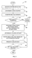
- FIG. 6 is a flow chart illustrating the algorithm or method of friction stir spot welding in accordance with the present invention.
- a friction stir spot welding (FSSW) system or apparatus partially illustrated and identified generally in FIG. 1 as element 10 .
- the present invention will be described herein with respect to the FSSW apparatus 10 as an exemplary application by which the present invention may be incorporated; the present invention by no means being limited to the particular configuration or structure of FIGS. 1-4 .
- the present invention can be used in a variety of manufacturing processes.
- the apparatus and method provided herein can be employed for operating on a single workpiece, for joining two or more workpieces together, or for joining two ends of a single workpiece together, as will be explained in detail hereinafter.
- the present invention can be applied in both 2-dimensional and 3-dimensional applications.
- the FSSW system 10 includes an anvil or support 12 and a frame 14 , also referred to by those skilled in the art as a “C-Frame,” “a weld gun,” or a “gun”.
- the anvil 12 is mounted, preferably in a repositionable manner, to the frame 14 so that a single workpiece W, as depicted in FIG.1 , or a plurality of workpieces, represented herein by first and second workpieces Wl, W 2 , as depicted in FIGS. 2 and 4 , may abut against and be securely supported by the anvil 12 during welding.
- the FSSW system 10 also includes a FSSW weld tool 16 and a tool sleeve 18 , wherein the weld tool 16 and tool sleeve 18 are preferably arranged to be coaxially opposed with the anvil 12 along axis Z, as depicted in FIG. 1 .
- the anvil 12 and tool sleeve 18 could be of any functional geometric shape.
- the FSSW system 10 also includes a controller, depicted in FIG. 1 in an exemplary embodiment as a micro-processor based electronic control unit (ECU) 11 , having a suitable amount of programmable memory 13 .
- the controller 11 further includes a control method or algorithm 100 of friction stir spot welding, as will be discussed in detail below.
- the FSSW system 10 also includes a plurality of sensing mechanisms, represented herein by sensors/transducers S 1 -S 6 , connected to the controller 111 and configured to continuously monitor, track, and/or detect various system parameters, as will be discussed in detail below.
- the sensors S 1 -S 6 are also configured to transmit signals to the controller 11 representative or indicative of the aforementioned parameters being monitored, tracked, or detected.
- the means of communication between the sensors S 1 -S 6 and controller 11 is not restricted to the use of electric cables (“by wire”), but may be, for example, by radio frequency and other wireless technology, or by electromechanical communication (not shown.)
- the FSSW system 10 also includes a driving or plunging mechanism and a tool rotating mechanism, such as servomechanisms 15 and 17 , respectively, that are connected to the controller 11 via one or more of the sensors S 1 -S 6 , or directly (depicted in phantom in FIG. 1 ).
- the plunging and rotating mechanisms 15 , 17 can be, by way of example, electric, pneumatic, hydraulic, and/or magnetic devices.
- the controller 11 is configured or programmed, in part, to control the operation of the plunging and rotating mechanisms 15 , 17 preferably based upon the signals of sensors S 1 -S 6 .
- sensors S 1 and S 2 are preferably respectively configured to detect the position and plunge speed, and apply pressure, also referred to herein as the plunge force, of the weld tool 16 , functioning, for example, as contact state detection means.
- sensors S 3 and S 4 are preferably respectively configured to detect the rotational speed and apply torque of the weld tool 16 .
- sensors S 5 and S 6 are preferably respectively configured to detect the weld gun deflection (depicted generally in phantom in FIG. 1 as D) and weld gun growth (depicted generally in phantom as G in FIG. 4 )
- the weld tool 16 is preferably a non-consumable, wear resistant (e.g., hardened steels, ceramics, etc.) monolithic or unitary cylindrical piece having a first end 26 , a body portion 30 , and a second end 20 having a threaded or otherwise profiled pin or probe 21 projecting substantially perpendicular from a shouldered portion 28 .
- the first end 26 is intended to be inserted into a receiving face 32 of the tool sleeve 18 , and be removably secured, attached, or locked to the tool sleeve 18 via interconnecting threads 34 .
- the probe 21 , shouldered portion 28 , body 30 , and first end 26 of the weld tool 16 are preferably coaxially disposed with the tool sleeve 18 to be translated along and rotated about axis Z by the plunging and rotating mechanisms 15 , 17 , respectively.
- the friction stir spot welding of the present invention is performed using the cylindrical welding tool 16 .
- a pair of workpieces W 1 and W 2 are superposed, abutted, or overlapped to form a joining or operating region, identified generally as 40 in FIG. 4 .
- the sum total of the first workpiece thickness A and second workpiece thickness B is referred to hereinafter as the “total stack-up” thickness.
- the total stack-up thickness may also be defined as the thickness of the single workpiece W, as shown in FIG. 1 , or the sum total thickness of a multitude of workpieces (not shown), within the intended scope of the present invention.
- the weld tool 16 is pressed or plunged one or more times, as depicted by arrows A 1 and A 2 , into the joining region 40 through the top planes 36 , 38 of workpieces W 1 , W 2 , respectively, and contemporaneously rotated, as depicted by arrow R.
- the highly pressurized plunging and rotation of the welding tool 16 generates large amounts of frictional heat between the probe 21 , the shoulder 28 , and the workpieces W 1 , W 2 .
- This operation/process produces a local region of highly plasticized material (identified generally by element 41 in FIG. 4 ) around the probe 21 .
- P the total stack-up thickness (A+B) less a bottom thickness or dimension C.
- P (A+B) ⁇ C.
- the rotation R of the weld tool 16 and ensuing frictional heat effectively “stirs” the plasticized material 41 in the operating region 40 .
- the direction of rotation R can be clockwise (as illustrated in FIG. 2 ) or counterclockwise (not shown), without departing from the scope of the present invention.
- the second end 20 (including the probe 21 and shoulder portion 28 ) is withdrawn from the operating region 40 , illustrated by arrow A 2 of FIG. 2 , allowing the plasticized material 41 to cool and harden, thereby reversing the plasticized condition.
- a FSSW weld 24 is formed, joining the first workpiece W 1 to the second workpiece W 2 .
- the contours of the resulting FSSW weld 24 are generally defined by the geometry of the weld tool 16 , namely the diameter E of the body portion 30 , and the diameter H of the probe 21 , as best seen in FIG. 4 .
- the probe 21 preferably includes a plurality of threads or steps 42 disposed along a frusta-conical contour.
- the threads 42 are intended to promote coalescence by “stirring” or “mixing” the plasticized material 41 contributed by each of the first and second workpieces W 1 , W 2 to the operating region 40 .
- FIG. 3 illustrates the probe 21 with a frusta-conical geometry, it is considered to be within the scope of the present invention that the probe 21 take on other functional shapes (i.e., cylindrical or generally contoured.)
- the threads 42 may be completely omitted from the structure provided in FIG. 3 , or may take on additional configurations, such as, by way of example, stepped spirals (not shown.)
- a solid-state welding technique namely the method of friction stir spot welding (“FSSW”) is shown generally as 100 in accordance with the present invention.
- the method or algorithm 100 is described herein with respect to the structure illustrated in FIGS. 1 through 4 .
- the present invention may also be applied to other types of solid-state welding techniques.
- the method 100 can be applied to all FSSW welding machines, including, but not limited to, robot-carried C-guns, pedestal-type machines and gantry-type machines.
- the method 100 begins with first continuously monitoring or determining a system deflection D for a predetermined plunge force F, as step 101 .
- the force necessary to obtain a FSSW joint 24 is relatively large, for instance as high as 18 kN for welding aluminum. Consequently, the C-Frame 14 will deflect under these forces due to the bending of the various components used to fabricate the C-Frame 14 .
- FIGS. 1 and 4 illustrates the FSSW system 10 under load, the deflection D of the C-Frame 14 depicted generally in phantom, while the solid lines of FIG. 1 illustrate the FSSW system 10 absent any load (identified generally by element 22 .)
- it is necessary to determine the amount of deflection D present in the FSSW system 10 as will be further clarified below.
- a zero position ⁇ is also determined and/or calibrated, as step 103 .
- the zero position ⁇ is preferably defined relative to the top surface 44 of the anvil 12 .
- the zero position ⁇ may also be defined with respect to the bottom surface 39 of the bottom workpiece W 2 .
- weld gun growth G results in the zero-position ⁇ unintentionally changing. Accordingly, the FSSW system 10 should properly account for the gun growth G in order to provide an accurate and the plunge distance P.
- a first means of achieving accurate plunge distance control in accordance with the present invention is to monitor and compensate for this growth by properly offsetting the FSSW system 10 .
- step 105 requires systematically monitoring weld gun growth G to determine if the weld gun growth G exceeds a predetermined tolerance or threshold, outside of which the mechanical properties of FSSW weld 24 will be compromised.
- step 107 includes determining if the weld gun growth G exceeds the predetermined tolerance and, as step 107 A, compensating or adjusting the FSSW system 10 in response to the weld gun growth G exceeding the predetermined tolerance. However, if the weld gun growth G does not exceed the predetermined tolerance, step 107 A is bypassed during the iteration of method 100 .
- One means of compensating for the weld gun growth G is to place temperature sensors or transducers, e.g., sensor S 6 of FIG. 1 , at critical locations in the FSSW system 10 , such as the hot parts of the spindle (not shown).
- a temperature compensation program (not shown) is employed or implemented to calculate a temperature offset necessary to counteract or neutralize the effect of the weld gun growth G.
- a threshold weld number or weld count can be determined wherein the weld gun growth G will expectedly exceed the predetermined tolerance.
- the FS SW system 10 (preferably the zero position ⁇ ) is recalibrated if the threshold weld number has been reached. It should be noted that steps 105 and 107 may be performed at any point within, or actively throughout the method 100 to compensate for the weld gun growth G.
- Bottom thickness is critical to the strength of the FSSW weld 24 .
- the graph in FIG. 5 provides an exemplary relationship between the bottom thickness C, in millimeters (mm), and lap-shear strength of a FSSW weld 24 , in kilo-Newtons (kN, on the primary Y-axis) and pounds (lb, on the secondary Y-axis). Even minor unintended variations in plunge distance (on the scale of a tenth of a millimeter) and hence in bottom thickness can result in the final work product failing to comply with pre-established product tolerances. For example, FIG.
- the method 100 requires that the plunge distance P be controlled closely and consistently throughout the welding process to achieve the mechanical properties necessary to meet pre-established weld tolerances uniformly among the series of resultant FSSW welds 24 , e.g., FIG. 4 .
- the bottom thickness C that is used to program the FSSW system 10 to reach the plunge distance P.
- the bottom thickness C also provides a convenient way for quality control and inspection.
- this equation is valid only when there is no deflection D in the FSSW system 10 ; namely, there is no deflection D of the weld gun 14 .
- Step 101 includes calculating a system deflection D for a predetermined plunge force F.
- step 101 may be completed during calibration (prior to a welding operation) or in real-time throughout the welding process 100 (as illustrated in FIG. 1 .)
- the control system e.g., controller 11
- the control system e.g., controller 11
- the control system e.g., controller 11
- the weld gun 14 is first set at the zero position ⁇ (preferably anvil surface 44 ) at a minimum load—generally, a small load, which causes a very small deflection, is applied to maintain positive contact between the weld tool and the anvil.
- the position of the gun 14 is thereafter recorded, i.e., by signals from sensors S 1 and S 2 , when the weld gun 14 is subjected to a peak program force, e.g., force F of FIG. 1 .
- step 109 bottom thickness, spindle speed, plunge force and plunge speed are programmed.
- method 100 includes calculating the plunge distance P based upon at least the stack-up thickness (A+B), bottom thickness C, and system deflection D, as step 111 .
- P (A+B) ⁇ C+D.
- deflection D can be determined by using a pre-calibrated force-deflection curve where the force input is derived from a pre-calibrated motor current-force relationship.
- step 113 includes causing the weld tool 16 to enter the operating or joining region 40 at the plunge force F and plunge speed, while contemporaneously causing relative rotational or cyclic movement R between the second end 20 of the weld tool 16 , including the probe 21 and shoulder portion 28 , and the workpiece W, FIG. 1 , or workpieces W 1 , W 2 , FIG. 2 , whereby frictional heat and pressure is generated (as described above), thereby causing the operating/joining region 40 to take up a plasticized condition.
- the method 100 also includes, as step 115 , promoting coalescence after the operating region 40 has taken up a plasticized condition 41 , and before completion of the welding operation.
- Step 115 may be accomplished solely via the threads 42 on the probe 21 , as described above.
- coalescence also be promoted by programming the FSSW system 10 to complete a dwell operation, whereby the weld tool 16 rotates and dwells at a predetermined dwell depth, illustrated generally as Q in FIG. 4 , in the operating/joining region 40 , for a predetermined dwell time or interval.
- the dwell depth Q and dwell time can be varied to further manipulate weld heat input to the plasticized region/material 41 in order to achieve desired mechanical properties of the FSSW welds 24 .
- the dwell operation may be performed more than once in any given operating region 40 , may be performed at varying depths, and/or with varying rotational speeds R to achieve varying results.
- the rotational and plunge speeds between any two dwell positions may be different. It is also within the scope and spirit of the present invention to omit step 115 .
- step 117 requires that the weld tool 16 be programmed to exit the operating/joining region 40 after the bottom thickness C has been reached, and allowing the plasticized condition 41 of the operating or joining region 40 to cool down and harden, thereby completing a single weld or operation on the workpiece W, or workpieces W 1 , W 2 .
- the weld control achieves the actual bottom thickness C, the welding operation is stopped.
- the method 100 preferably includes at least steps 101 - 117 . However, it is within the scope and spirit of the present invention to omit steps, include additional steps, and/or modify the order presented in FIG. 6 . It should be further noted that the method 100 represents a single FSSW weld operation. However, it is contemplated that the method 100 be applied in a systematic manner to produce multiple FSSW welds 24 , as illustrated in FIG. 2 . Furthermore, the method 100 can be used in a variety of manufacturing processes, by way of example, for operating on a single workpiece W ( FIG. 1 ), for joining two or more workpieces together (W 1 and W 2 of FIGS. 2 and 4 ), or for joining two ends of a single workpiece together (i.e. to form tube or column.)
- the method 100 provides for consistency in resultant mechanical properties of the FSSW welds 24 , and prevents circumstances that may interfere with the strength or integrity of welds 24 , such as a gap(s) between overlapped workpieces W 1 , W 2 , or uncontrolled FSSW system 10 temperature changes during continuous welding.
- the above method 100 prevents the weld tool 16 from producing a hole through the bottom work piece W 2 and/or plunging into and damaging the anvil 12 , even when the workpiece W, or workpieces W 1 , W 2 are absent.
- this invention allows a user of the FSSW system 10 to manipulate weld heat input by causing the rotating FSSW tool to dwell at desired depths within the work piece W or workpieces W 1 , W 2 for a predetermined time interval to achieve desired mechanical properties of the FSSW joint. This dwell operation may also improve the appearance of weld flash.
Abstract
Description
Claims (25)
Priority Applications (1)
| Application Number | Priority Date | Filing Date | Title |
|---|---|---|---|
| US11/930,956 US8011560B2 (en) | 2006-12-12 | 2007-10-31 | Apparatus and method of solid-state welding |
Applications Claiming Priority (2)
| Application Number | Priority Date | Filing Date | Title |
|---|---|---|---|
| US86962606P | 2006-12-12 | 2006-12-12 | |
| US11/930,956 US8011560B2 (en) | 2006-12-12 | 2007-10-31 | Apparatus and method of solid-state welding |
Publications (2)
| Publication Number | Publication Date |
|---|---|
| US20080135601A1 US20080135601A1 (en) | 2008-06-12 |
| US8011560B2 true US8011560B2 (en) | 2011-09-06 |
Family
ID=39496784
Family Applications (1)
| Application Number | Title | Priority Date | Filing Date |
|---|---|---|---|
| US11/930,956 Expired - Fee Related US8011560B2 (en) | 2006-12-12 | 2007-10-31 | Apparatus and method of solid-state welding |
Country Status (1)
| Country | Link |
|---|---|
| US (1) | US8011560B2 (en) |
Cited By (6)
| Publication number | Priority date | Publication date | Assignee | Title |
|---|---|---|---|---|
| US8556156B1 (en) | 2012-08-30 | 2013-10-15 | Apple Inc. | Dynamic adjustment of friction stir welding process parameters based on weld temperature |
| US8800847B2 (en) | 2012-06-09 | 2014-08-12 | Apple Inc. | Dynamic path correction of friction stir welding |
| US20140299650A1 (en) * | 2013-02-01 | 2014-10-09 | Fluor Technologies Corporation | Friction stir welding devices and methods for tandem tool and anvil |
| WO2017090239A1 (en) * | 2015-11-24 | 2017-06-01 | 川崎重工業株式会社 | Friction spot joining device and friction spot joining method |
| US10286481B2 (en) | 2012-11-05 | 2019-05-14 | Fluor Technologies Corporation | FSW tool with graduated composition change |
| US11130192B2 (en) * | 2017-08-30 | 2021-09-28 | Mazak Corporation | Instrumented tool handler for friction stir welding |
Families Citing this family (18)
| Publication number | Priority date | Publication date | Assignee | Title |
|---|---|---|---|---|
| SE0400320D0 (en) * | 2004-02-06 | 2004-02-06 | Abb Ab | Control method for robots |
| EP2015064B1 (en) * | 2006-04-11 | 2017-07-05 | Kawasaki Jukogyo Kabushiki Kaisha | Method and device for inspecting object formed by friction stir joining |
| DE102008063277A1 (en) * | 2008-12-29 | 2010-07-08 | Bwg Bergwerk- Und Walzwerk-Maschinenbau Gmbh | Method and device for joining metal strips |
| FI20105707A (en) * | 2010-06-18 | 2011-12-19 | Outotec Oyj | PROCEDURES AND DEVICES FOR ASSEMBLING STRIPED METAL REMOVAL SHEETS |
| US8052029B1 (en) * | 2010-09-01 | 2011-11-08 | GM Global Technology Operations LLC | Method of calibrating a friction stir spot welding system |
| JP5815961B2 (en) * | 2011-03-18 | 2015-11-17 | 川崎重工業株式会社 | Friction stir spot welding apparatus and friction stir spot welding method |
| CN104169038B (en) * | 2012-02-09 | 2016-11-09 | 依赛彼公司 | Backing for friction stir weld configures |
| SI2689882T1 (en) * | 2012-07-26 | 2020-03-31 | Tata Technologies Pte Ltd. | An apparatus and process for joining homogeneous and heterogeneous materials with customized interface properties |
| US9165902B2 (en) * | 2013-12-17 | 2015-10-20 | Kulicke And Soffa Industries, Inc. | Methods of operating bonding machines for bonding semiconductor elements, and bonding machines |
| EP3090828B1 (en) * | 2013-12-27 | 2020-03-25 | Kawasaki Jukogyo Kabushiki Kaisha | Friction stir spot welding apparatus, and friction stir spot welding method, with a device for detecting perpendicularity to surface for friction stir spot welding |
| JP2016124002A (en) * | 2014-12-26 | 2016-07-11 | トヨタ自動車株式会社 | Friction point joint device and friction point joint method |
| US10919108B2 (en) * | 2015-09-14 | 2021-02-16 | Kawasaki Jukogyo Kabushiki Kaisha | Configured to set the plunging force |
| JP6650801B2 (en) * | 2016-03-17 | 2020-02-19 | 川崎重工業株式会社 | Friction stir spot welding method and friction stir spot welding apparatus |
| CN109070261B (en) * | 2016-03-31 | 2021-06-01 | 杰富意钢铁株式会社 | Friction stir welding method and apparatus for structural steel |
| DE102018103991A1 (en) * | 2018-02-22 | 2019-08-22 | Bayerische Motoren Werke Aktiengesellschaft | friction welding |
| JP7134858B2 (en) * | 2018-12-20 | 2022-09-12 | 株式会社東芝 | Crack repair method and crack repair device |
| US10442029B1 (en) * | 2019-04-10 | 2019-10-15 | King Saud University | Method of friction stir spot welding |
| CN112605521B (en) * | 2020-12-11 | 2022-07-26 | 中车唐山机车车辆有限公司 | Control method, device and system for friction stir welding |
Citations (7)
| Publication number | Priority date | Publication date | Assignee | Title |
|---|---|---|---|---|
| US3482296A (en) | 1966-09-19 | 1969-12-09 | Gen Motors Corp | Method for the integrated welding and heat treating of hardenable parts |
| US5460317A (en) | 1991-12-06 | 1995-10-24 | The Welding Institute | Friction welding |
| US5813592A (en) | 1994-03-28 | 1998-09-29 | The Welding Institute | Friction stir welding |
| US6601751B2 (en) | 2000-04-28 | 2003-08-05 | Mazda Motor Corporation | Method and apparatus for joining |
| US6806436B2 (en) | 2000-12-06 | 2004-10-19 | Toyota Shatai Kabushiki Kaisha | Series spot welding method, device for carrying out the method, and electrodes employed in the method or the device |
| US20050029331A1 (en) * | 2003-05-14 | 2005-02-10 | Kawasaki Jukogyo Kabushiki Kaisha | Friction stir welding method and friction stir welding device |
| US20070164086A1 (en) * | 2005-12-06 | 2007-07-19 | Keith Hochhalter | Rotatable tool and apparatus therefor |
-
2007
- 2007-10-31 US US11/930,956 patent/US8011560B2/en not_active Expired - Fee Related
Patent Citations (9)
| Publication number | Priority date | Publication date | Assignee | Title |
|---|---|---|---|---|
| US3482296A (en) | 1966-09-19 | 1969-12-09 | Gen Motors Corp | Method for the integrated welding and heat treating of hardenable parts |
| US5460317A (en) | 1991-12-06 | 1995-10-24 | The Welding Institute | Friction welding |
| US5460317B1 (en) | 1991-12-06 | 1997-12-09 | Welding Inst | Friction welding |
| US5813592A (en) | 1994-03-28 | 1998-09-29 | The Welding Institute | Friction stir welding |
| US6601751B2 (en) | 2000-04-28 | 2003-08-05 | Mazda Motor Corporation | Method and apparatus for joining |
| US6806436B2 (en) | 2000-12-06 | 2004-10-19 | Toyota Shatai Kabushiki Kaisha | Series spot welding method, device for carrying out the method, and electrodes employed in the method or the device |
| US20050029331A1 (en) * | 2003-05-14 | 2005-02-10 | Kawasaki Jukogyo Kabushiki Kaisha | Friction stir welding method and friction stir welding device |
| US7121451B2 (en) | 2003-05-14 | 2006-10-17 | Kawasaki Jukogyo Kabushiki Kaisha | Friction stir welding method and friction stir welding device |
| US20070164086A1 (en) * | 2005-12-06 | 2007-07-19 | Keith Hochhalter | Rotatable tool and apparatus therefor |
Cited By (8)
| Publication number | Priority date | Publication date | Assignee | Title |
|---|---|---|---|---|
| US8800847B2 (en) | 2012-06-09 | 2014-08-12 | Apple Inc. | Dynamic path correction of friction stir welding |
| US8556156B1 (en) | 2012-08-30 | 2013-10-15 | Apple Inc. | Dynamic adjustment of friction stir welding process parameters based on weld temperature |
| US10286481B2 (en) | 2012-11-05 | 2019-05-14 | Fluor Technologies Corporation | FSW tool with graduated composition change |
| US20140299650A1 (en) * | 2013-02-01 | 2014-10-09 | Fluor Technologies Corporation | Friction stir welding devices and methods for tandem tool and anvil |
| US9174302B2 (en) * | 2013-02-01 | 2015-11-03 | Fluor Technologies Corporation | Friction stir welding devices and methods for tandem tool and anvil |
| US9457423B2 (en) * | 2013-02-01 | 2016-10-04 | Fluor Corporation | Friction stir welding devices and methods for tandem tool and anvil |
| WO2017090239A1 (en) * | 2015-11-24 | 2017-06-01 | 川崎重工業株式会社 | Friction spot joining device and friction spot joining method |
| US11130192B2 (en) * | 2017-08-30 | 2021-09-28 | Mazak Corporation | Instrumented tool handler for friction stir welding |
Also Published As
| Publication number | Publication date |
|---|---|
| US20080135601A1 (en) | 2008-06-12 |
Similar Documents
| Publication | Publication Date | Title |
|---|---|---|
| US8011560B2 (en) | Apparatus and method of solid-state welding | |
| US6497355B1 (en) | System for controlling the stirring pin of a friction stir welding apparatus | |
| EP2168708B1 (en) | Friction stir welding method and system. | |
| JP5815961B2 (en) | Friction stir spot welding apparatus and friction stir spot welding method | |
| US7464852B2 (en) | Method and apparatus for friction stir welding | |
| US8052029B1 (en) | Method of calibrating a friction stir spot welding system | |
| US7431194B2 (en) | Joining structural members by friction welding | |
| US6264088B1 (en) | Welding assembly for friction stir welding | |
| US5971252A (en) | Friction stir welding process to repair voids in aluminum alloys | |
| US7275675B1 (en) | Friction stir weld tools | |
| US20060175382A1 (en) | Tool geometries for friction stir spot welding of high melting temperature alloys | |
| US7455210B2 (en) | Processing operation control method, processing operation controller, computer program for carrying out the method, information storage medium storing the computer program | |
| JP2000301361A (en) | Friction agitating joining method | |
| WO2020179661A1 (en) | Joining device for friction stirring point, joined article having joined friction stirring point, and shoulder member | |
| KR20140009055A (en) | Aluminum alloy propeller shaft and friction welding process thereof | |
| CA2597727A1 (en) | Tool geometries for friction stir spot welding of high melting temperature alloys | |
| JP6412627B1 (en) | Friction stir welding apparatus, friction stir welding method, friction stir welding apparatus with database, friction stir welding method using database, control apparatus for friction stir welding apparatus | |
| JP5048583B2 (en) | Friction stir welding method and friction stir welding apparatus | |
| US8651361B1 (en) | Method for angular oscillation friction welding to an axially symmetric weld surface | |
| Shrivastava et al. | Prediction of unit process life cycle inventory (UPLCI) energy consumption in a friction stir weld | |
| Mastanaiah et al. | Evolution and current practices in friction stir welding tool design | |
| Bolmsjoe et al. | Robotic Friction Stir Welding of complex geometry and mixed materials | |
| JP6307005B2 (en) | Evaluation method of joining state in friction stir spot welding, and friction stir spot welding apparatus using this evaluation method | |
| JP2023147697A (en) | Friction stirring joining device and friction stirring joining method | |
| GB2614889A (en) | Friction stir processing method |
Legal Events
| Date | Code | Title | Description |
|---|---|---|---|
| AS | Assignment |
Owner name: GM GLOBAL TECHNOLOGY OPERATIONS, INC., MICHIGAN Free format text: ASSIGNMENT OF ASSIGNORS INTEREST;ASSIGNORS:CHEN, YEN-LUNG;HALL, MARK T.;TOTTEN, ROBERT L.;AND OTHERS;REEL/FRAME:020480/0213;SIGNING DATES FROM 20071101 TO 20080123 Owner name: GM GLOBAL TECHNOLOGY OPERATIONS, INC., MICHIGAN Free format text: ASSIGNMENT OF ASSIGNORS INTEREST;ASSIGNORS:CHEN, YEN-LUNG;HALL, MARK T.;TOTTEN, ROBERT L.;AND OTHERS;SIGNING DATES FROM 20071101 TO 20080123;REEL/FRAME:020480/0213 |
|
| AS | Assignment |
Owner name: UNITED STATES DEPARTMENT OF THE TREASURY, DISTRICT Free format text: SECURITY AGREEMENT;ASSIGNOR:GM GLOBAL TECHNOLOGY OPERATIONS, INC.;REEL/FRAME:022201/0448 Effective date: 20081231 Owner name: UNITED STATES DEPARTMENT OF THE TREASURY,DISTRICT Free format text: SECURITY AGREEMENT;ASSIGNOR:GM GLOBAL TECHNOLOGY OPERATIONS, INC.;REEL/FRAME:022201/0448 Effective date: 20081231 |
|
| AS | Assignment |
Owner name: CITICORP USA, INC. AS AGENT FOR BANK PRIORITY SECU Free format text: SECURITY AGREEMENT;ASSIGNOR:GM GLOBAL TECHNOLOGY OPERATIONS, INC.;REEL/FRAME:022554/0479 Effective date: 20090409 Owner name: CITICORP USA, INC. AS AGENT FOR HEDGE PRIORITY SEC Free format text: SECURITY AGREEMENT;ASSIGNOR:GM GLOBAL TECHNOLOGY OPERATIONS, INC.;REEL/FRAME:022554/0479 Effective date: 20090409 |
|
| AS | Assignment |
Owner name: GM GLOBAL TECHNOLOGY OPERATIONS, INC., MICHIGAN Free format text: RELEASE BY SECURED PARTY;ASSIGNOR:UNITED STATES DEPARTMENT OF THE TREASURY;REEL/FRAME:023124/0670 Effective date: 20090709 Owner name: GM GLOBAL TECHNOLOGY OPERATIONS, INC.,MICHIGAN Free format text: RELEASE BY SECURED PARTY;ASSIGNOR:UNITED STATES DEPARTMENT OF THE TREASURY;REEL/FRAME:023124/0670 Effective date: 20090709 |
|
| AS | Assignment |
Owner name: GM GLOBAL TECHNOLOGY OPERATIONS, INC., MICHIGAN Free format text: RELEASE BY SECURED PARTY;ASSIGNORS:CITICORP USA, INC. AS AGENT FOR BANK PRIORITY SECURED PARTIES;CITICORP USA, INC. AS AGENT FOR HEDGE PRIORITY SECURED PARTIES;REEL/FRAME:023155/0880 Effective date: 20090814 Owner name: GM GLOBAL TECHNOLOGY OPERATIONS, INC.,MICHIGAN Free format text: RELEASE BY SECURED PARTY;ASSIGNORS:CITICORP USA, INC. AS AGENT FOR BANK PRIORITY SECURED PARTIES;CITICORP USA, INC. AS AGENT FOR HEDGE PRIORITY SECURED PARTIES;REEL/FRAME:023155/0880 Effective date: 20090814 |
|
| AS | Assignment |
Owner name: UNITED STATES DEPARTMENT OF THE TREASURY, DISTRICT Free format text: SECURITY AGREEMENT;ASSIGNOR:GM GLOBAL TECHNOLOGY OPERATIONS, INC.;REEL/FRAME:023156/0215 Effective date: 20090710 Owner name: UNITED STATES DEPARTMENT OF THE TREASURY,DISTRICT Free format text: SECURITY AGREEMENT;ASSIGNOR:GM GLOBAL TECHNOLOGY OPERATIONS, INC.;REEL/FRAME:023156/0215 Effective date: 20090710 |
|
| AS | Assignment |
Owner name: UAW RETIREE MEDICAL BENEFITS TRUST, MICHIGAN Free format text: SECURITY AGREEMENT;ASSIGNOR:GM GLOBAL TECHNOLOGY OPERATIONS, INC.;REEL/FRAME:023162/0187 Effective date: 20090710 Owner name: UAW RETIREE MEDICAL BENEFITS TRUST,MICHIGAN Free format text: SECURITY AGREEMENT;ASSIGNOR:GM GLOBAL TECHNOLOGY OPERATIONS, INC.;REEL/FRAME:023162/0187 Effective date: 20090710 |
|
| AS | Assignment |
Owner name: GM GLOBAL TECHNOLOGY OPERATIONS, INC., MICHIGAN Free format text: RELEASE BY SECURED PARTY;ASSIGNOR:UNITED STATES DEPARTMENT OF THE TREASURY;REEL/FRAME:025245/0780 Effective date: 20100420 |
|
| AS | Assignment |
Owner name: GM GLOBAL TECHNOLOGY OPERATIONS, INC., MICHIGAN Free format text: RELEASE BY SECURED PARTY;ASSIGNOR:UAW RETIREE MEDICAL BENEFITS TRUST;REEL/FRAME:025315/0001 Effective date: 20101026 |
|
| AS | Assignment |
Owner name: WILMINGTON TRUST COMPANY, DELAWARE Free format text: SECURITY AGREEMENT;ASSIGNOR:GM GLOBAL TECHNOLOGY OPERATIONS, INC.;REEL/FRAME:025324/0057 Effective date: 20101027 |
|
| FEPP | Fee payment procedure |
Free format text: PAYOR NUMBER ASSIGNED (ORIGINAL EVENT CODE: ASPN); ENTITY STATUS OF PATENT OWNER: LARGE ENTITY |
|
| AS | Assignment |
Owner name: GM GLOBAL TECHNOLOGY OPERATIONS LLC, MICHIGAN Free format text: CHANGE OF NAME;ASSIGNOR:GM GLOBAL TECHNOLOGY OPERATIONS, INC.;REEL/FRAME:025781/0035 Effective date: 20101202 |
|
| STCF | Information on status: patent grant |
Free format text: PATENTED CASE |
|
| AS | Assignment |
Owner name: GM GLOBAL TECHNOLOGY OPERATIONS LLC, MICHIGAN Free format text: RELEASE BY SECURED PARTY;ASSIGNOR:WILMINGTON TRUST COMPANY;REEL/FRAME:034185/0587 Effective date: 20141017 |
|
| FPAY | Fee payment |
Year of fee payment: 4 |
|
| FEPP | Fee payment procedure |
Free format text: MAINTENANCE FEE REMINDER MAILED (ORIGINAL EVENT CODE: REM.); ENTITY STATUS OF PATENT OWNER: LARGE ENTITY |
|
| LAPS | Lapse for failure to pay maintenance fees |
Free format text: PATENT EXPIRED FOR FAILURE TO PAY MAINTENANCE FEES (ORIGINAL EVENT CODE: EXP.); ENTITY STATUS OF PATENT OWNER: LARGE ENTITY |
|
| STCH | Information on status: patent discontinuation |
Free format text: PATENT EXPIRED DUE TO NONPAYMENT OF MAINTENANCE FEES UNDER 37 CFR 1.362 |
|
| FP | Lapsed due to failure to pay maintenance fee |
Effective date: 20190906 |