US8013330B2 - Compound for organic electroluminescent device and organic electroluminescent device - Google Patents
Compound for organic electroluminescent device and organic electroluminescent device Download PDFInfo
- Publication number
- US8013330B2 US8013330B2 US12/600,781 US60078108A US8013330B2 US 8013330 B2 US8013330 B2 US 8013330B2 US 60078108 A US60078108 A US 60078108A US 8013330 B2 US8013330 B2 US 8013330B2
- Authority
- US
- United States
- Prior art keywords
- group
- light
- compound
- organic electroluminescent
- electroluminescent device
- Prior art date
- Legal status (The legal status is an assumption and is not a legal conclusion. Google has not performed a legal analysis and makes no representation as to the accuracy of the status listed.)
- Active, expires
Links
- 0 *C.*C.*C.*C.*N1CCC2=CC=CC=C21.*N1CCCC1.*[Ar]N1CCC2=C1C=CC=C2.C1=CC=CC=C1.C1=CC=CC=C1 Chemical compound *C.*C.*C.*C.*N1CCC2=CC=CC=C21.*N1CCCC1.*[Ar]N1CCC2=C1C=CC=C2.C1=CC=CC=C1.C1=CC=CC=C1 0.000 description 6
- PQOORWVBIIYTLU-UHFFFAOYSA-N CC1=[Y]C(C)=[Y]C(C)=[Y]1 Chemical compound CC1=[Y]C(C)=[Y]C(C)=[Y]1 PQOORWVBIIYTLU-UHFFFAOYSA-N 0.000 description 2
- AHKPOAUIMKTBHS-CXGCMCJLSA-K C1=CC2=C3C4=C(C=CC=C4C=C2)[Ir]24(C5=C6C(=CC=C5)/C=C\C5=C6N2=CC=C5)(C2=C5C(=CC=C2)/C=C\C2=C5N4=CC=C2)N3=C1.C1=CC=N2C(=C1)C1=C(C=CC=C1)[Pt]21C2=C(C=CC=C2)C2=CC=CC=N21.C1=CC=N2C(=C1)C1=C(C=CC=C1)[Rh]213(C2=C(C=CC=C2)C2=CC=CC=N21)C1=C(C=CC=C1)C1=CC=CC=N13.CC1=CC(C)=O[Ir@@]2(O1)C1=C(C(F)=CC(F)=C1)C1=CC=CC=N12.CC1=CC(C)=O[Ir@@]2(O1)C1=C(C=CC=C1)C1=CC=CC=N12.CC1=CC(C)=O[Ir@@]2(O1)C1=C/C=C/C=C\1C1=N2C2=C(C=CC=C2)S1 Chemical compound C1=CC2=C3C4=C(C=CC=C4C=C2)[Ir]24(C5=C6C(=CC=C5)/C=C\C5=C6N2=CC=C5)(C2=C5C(=CC=C2)/C=C\C2=C5N4=CC=C2)N3=C1.C1=CC=N2C(=C1)C1=C(C=CC=C1)[Pt]21C2=C(C=CC=C2)C2=CC=CC=N21.C1=CC=N2C(=C1)C1=C(C=CC=C1)[Rh]213(C2=C(C=CC=C2)C2=CC=CC=N21)C1=C(C=CC=C1)C1=CC=CC=N13.CC1=CC(C)=O[Ir@@]2(O1)C1=C(C(F)=CC(F)=C1)C1=CC=CC=N12.CC1=CC(C)=O[Ir@@]2(O1)C1=C(C=CC=C1)C1=CC=CC=N12.CC1=CC(C)=O[Ir@@]2(O1)C1=C/C=C/C=C\1C1=N2C2=C(C=CC=C2)S1 AHKPOAUIMKTBHS-CXGCMCJLSA-K 0.000 description 1
- PJCORGFRHHDKQY-BFYFKGCNSA-N C1=CC2=CC3=C(C=C2C=C1)/C1=N/C2=N4/C(=N\C5=N6/C(=N\C7=N8C(=NC3=N1[Pt@]846)C1=CC3=C(C=CC=C3)C=C17)C1=C5C=C3C=CC=CC3=C1)C1=CC3=C(C=CC=C3)C=C12.C1=CC=C(C2=C3C=CC4=N3[Pt@@]35N6C(=CC=C26)/C=C2/C=CC(=N23)/C(C2=CC=CC=C2)=C2/C=C/C(=C/4)N25)C=C1.C1=CC=C2C(=C1)C1=NC3=N4/C(=N\C5=N6/C(=N\C7=N8/C(=N\C2=N1[Pt@@]468)C1=C7C=CC=C1)C1=CC=CC=C15)C1=C3C=CC=C1 Chemical compound C1=CC2=CC3=C(C=C2C=C1)/C1=N/C2=N4/C(=N\C5=N6/C(=N\C7=N8C(=NC3=N1[Pt@]846)C1=CC3=C(C=CC=C3)C=C17)C1=C5C=C3C=CC=CC3=C1)C1=CC3=C(C=CC=C3)C=C12.C1=CC=C(C2=C3C=CC4=N3[Pt@@]35N6C(=CC=C26)/C=C2/C=CC(=N23)/C(C2=CC=CC=C2)=C2/C=C/C(=C/4)N25)C=C1.C1=CC=C2C(=C1)C1=NC3=N4/C(=N\C5=N6/C(=N\C7=N8/C(=N\C2=N1[Pt@@]468)C1=C7C=CC=C1)C1=CC=CC=C15)C1=C3C=CC=C1 PJCORGFRHHDKQY-BFYFKGCNSA-N 0.000 description 1
- GTXZTKVNINEWAY-UHFFFAOYSA-N C1=CC2=CC=CC(C3=NC(N4C5=C(C=CC=C5)C5=CC=C6C7=C(C=CC=C7)N(C7=CC=CC8=C7C=CC=C8)C6=C54)=NC(N4C5=C(C=CC=C5)C5=CC=C6C7=C(C=CC=C7)N(C7=C8C=CC=CC8=CC=C7)C6=C54)=N3)=C2C=C1.C1=CC=C(C2=CC=C3C(=C2)C2=C(C4=C(C=C2)C2=CC(C5=CC=CC=C5)=CC=C2N4C2=NC(C4=CC=CC=C4)=NC(N4C5=CC=C(C6=CC=CC=C6)C=C5C5=C4C4=C(C=C5)C5=CC(C6=CC=CC=C6)=CC=C5N4C4=CC=C5C=CC=CC5=C4)=N2)N3C2=CC3=C(C=CC=C3)C=C2)C=C1.C1=CC=C(C2=NC(N3C4=C(C=CC=C4)C4=CC=C5C6=C(C=CC=C6)N(C6=CC=C7C=CC8=C(C=CC=C8)C7=C6)C5=C43)=NC(N3C4=C(C=CC=C4)C4=CC=C5C6=C(C=CC=C6)N(C6=CC7=C(C=C6)C=CC6=C7C=CC=C6)C5=C43)=N2)C=C1.C1=CC=C(C2=NC(N3C4=C(C=CC=C4)C4=CC=C5C6=C(C=CC=C6)N(C6=CC=CC7=C6C=CC=C7)C5=C43)=NC(N3C4=C(C=CC=C4)C4=CC=C5C6=C(C=CC=C6)N(C6=C7C=CC=CC7=CC=C6)C5=C43)=N2)C=C1.C1=CC=C(N2C3=C(C=CC=C3)C3=C4C5=C(C=CC=C5)N(C5=CC=CC=C5)C4=C4C(=C32)C2=C(C=CC=C2)N4C2=CC(C3=C4C=CC=CC4=CC=C3)=CC(N3C4=C(C=CC=C4)C4=C5C(=C6C7=C(C=CC=C7)N(C7=CC=CC=C7)C6=C43)C3=C(C=CC=C3)N5C3=CC=CC=C3)=C2)C=C1.C1=CC=C(N2C3=C(C=CC=C3)C3=CC=C4C5=C(C=CC=C5)N(C5=NC(N6C7=C(C=CC=C7)C7=CC=C8C9=C(C=CC=C9)N(C9=C%10C=CC=CC%10=CC=C9)C8=C76)=NC(C6=CC7=C(C=CC=C7)C=C6)=N5)C4=C32)C=C1.C1=CC=C(N2C3=CC=CC=C3C3=C2C2=C(C=C3)C3=CC=CC=C3N2C2=NC(C3=CC4=C(C=CC=C4)C=C3)=NC(N3C4=CC=CC=C4C4=C3C3=C(C=C4)C4=CC=CC=C4N3C3=CC=CC=C3)=N2)C=C1 Chemical compound C1=CC2=CC=CC(C3=NC(N4C5=C(C=CC=C5)C5=CC=C6C7=C(C=CC=C7)N(C7=CC=CC8=C7C=CC=C8)C6=C54)=NC(N4C5=C(C=CC=C5)C5=CC=C6C7=C(C=CC=C7)N(C7=C8C=CC=CC8=CC=C7)C6=C54)=N3)=C2C=C1.C1=CC=C(C2=CC=C3C(=C2)C2=C(C4=C(C=C2)C2=CC(C5=CC=CC=C5)=CC=C2N4C2=NC(C4=CC=CC=C4)=NC(N4C5=CC=C(C6=CC=CC=C6)C=C5C5=C4C4=C(C=C5)C5=CC(C6=CC=CC=C6)=CC=C5N4C4=CC=C5C=CC=CC5=C4)=N2)N3C2=CC3=C(C=CC=C3)C=C2)C=C1.C1=CC=C(C2=NC(N3C4=C(C=CC=C4)C4=CC=C5C6=C(C=CC=C6)N(C6=CC=C7C=CC8=C(C=CC=C8)C7=C6)C5=C43)=NC(N3C4=C(C=CC=C4)C4=CC=C5C6=C(C=CC=C6)N(C6=CC7=C(C=C6)C=CC6=C7C=CC=C6)C5=C43)=N2)C=C1.C1=CC=C(C2=NC(N3C4=C(C=CC=C4)C4=CC=C5C6=C(C=CC=C6)N(C6=CC=CC7=C6C=CC=C7)C5=C43)=NC(N3C4=C(C=CC=C4)C4=CC=C5C6=C(C=CC=C6)N(C6=C7C=CC=CC7=CC=C6)C5=C43)=N2)C=C1.C1=CC=C(N2C3=C(C=CC=C3)C3=C4C5=C(C=CC=C5)N(C5=CC=CC=C5)C4=C4C(=C32)C2=C(C=CC=C2)N4C2=CC(C3=C4C=CC=CC4=CC=C3)=CC(N3C4=C(C=CC=C4)C4=C5C(=C6C7=C(C=CC=C7)N(C7=CC=CC=C7)C6=C43)C3=C(C=CC=C3)N5C3=CC=CC=C3)=C2)C=C1.C1=CC=C(N2C3=C(C=CC=C3)C3=CC=C4C5=C(C=CC=C5)N(C5=NC(N6C7=C(C=CC=C7)C7=CC=C8C9=C(C=CC=C9)N(C9=C%10C=CC=CC%10=CC=C9)C8=C76)=NC(C6=CC7=C(C=CC=C7)C=C6)=N5)C4=C32)C=C1.C1=CC=C(N2C3=CC=CC=C3C3=C2C2=C(C=C3)C3=CC=CC=C3N2C2=NC(C3=CC4=C(C=CC=C4)C=C3)=NC(N3C4=CC=CC=C4C4=C3C3=C(C=C4)C4=CC=CC=C4N3C3=CC=CC=C3)=N2)C=C1 GTXZTKVNINEWAY-UHFFFAOYSA-N 0.000 description 1
- MQXCJRWFVJOZJA-HOVBHLEVSA-M C1=CC=C(C2=C3C=CC4=N3[Pt@@]35N6C2=CC=C6/C(C2=CC=CC=C2)=C2/C=CC(=N23)/C(C2=CC=CC=C2)=C2/C=C/C(=C/4C3=CC=CC=C3)N25)C=C1.CC1=CC(C)=O[Ir@@]2(O1)C1=C(SC3=C1C=CC=C3)C1=CC=CC=N12.CCC1=C(C)C2=CC3=C(CC)C(C)=C4/C=C5/C(CC)=C(C)C6=N5[Pt@@]5(N34)N3/C(=C\C1=N25)C(C)=C(CC)/C3=C/6.CCC1=C(CC)C2=N3C1=CC1=C(CC)C(CC)=C4/C=C5/C(CC)=C(CC)C6=N5[Pd@@]3(N14)N1/C(=C\2)C(CC)=C(CC)/C1=C/6.CCC1=C(CC)C2=N3C1=CC1=C(CC)C(CC)=C4/C=C5/C(CC)=C(CC)C6=N5[Pt@@]3(N14)N1/C(=C\2)C(CC)=C(CC)/C1=C/6 Chemical compound C1=CC=C(C2=C3C=CC4=N3[Pt@@]35N6C2=CC=C6/C(C2=CC=CC=C2)=C2/C=CC(=N23)/C(C2=CC=CC=C2)=C2/C=C/C(=C/4C3=CC=CC=C3)N25)C=C1.CC1=CC(C)=O[Ir@@]2(O1)C1=C(SC3=C1C=CC=C3)C1=CC=CC=N12.CCC1=C(C)C2=CC3=C(CC)C(C)=C4/C=C5/C(CC)=C(C)C6=N5[Pt@@]5(N34)N3/C(=C\C1=N25)C(C)=C(CC)/C3=C/6.CCC1=C(CC)C2=N3C1=CC1=C(CC)C(CC)=C4/C=C5/C(CC)=C(CC)C6=N5[Pd@@]3(N14)N1/C(=C\2)C(CC)=C(CC)/C1=C/6.CCC1=C(CC)C2=N3C1=CC1=C(CC)C(CC)=C4/C=C5/C(CC)=C(CC)C6=N5[Pt@@]3(N14)N1/C(=C\2)C(CC)=C(CC)/C1=C/6 MQXCJRWFVJOZJA-HOVBHLEVSA-M 0.000 description 1
- JQLDXXWXZUQVRC-UHFFFAOYSA-N C1=CC=C(C2=CC(N3C4=C(C=CC=C4)C4=CC=C5C6=C(C=CC=C6)N(C6=C7C=CC=CC7=CC=C6)C5=C43)=CC(N3C4=C(C=CC=C4)C4=CC=C5C6=C(C=CC=C6)N(C6=C7C=CC=CC7=CC=C6)C5=C43)=C2)C=C1.C1=CC=C(C2=CC(N3C4=C(C=CC=C4)C4=CC=C5C6=C(C=CC=C6)N(C6=CC=CC7=C6C=CC=C7)C5=C43)=NC(N3C4=C(C=CC=C4)C4=CC=C5C6=C(C=CC=C6)N(C6=C7C=CC=CC7=CC=C6)C5=C43)=C2)C=C1.C1=CC=C(C2=NC(N3C4=C(C=CC=C4)C4=CC=C5C6=C(C=CC=C6)N(C6=CC=C7C=CC=CC7=C6)C5=C43)=CC(N3C4=C(C=CC=C4)C4=CC=C5C6=C(C=CC=C6)N(C6=CC7=C(C=CC=C7)C=C6)C5=C43)=N2)C=C1.C1=CC=C(N2C3=C(C=CC=C3)C3=CC=C4C5=C(C=CC=C5)N(C5=CC(C6=CC7=C(C=CC=C7)C=C6)=CC(N6C7=C(C=CC=C7)C7=CC=C8C9=C(C=CC=C9)N(C9=CC=CC=C9)C8=C76)=C5)C4=C32)C=C1.C1=CC=C(N2C3=C(C=CC=C3)C3=CC=C4C5=C(C=CC=C5)N(C5=CC(C6=CC7=C(C=CC=C7)C=C6)=CC(N6C7=C(C=CC=C7)C7=CC=C8C9=C(C=CC=C9)N(C9=CC=CC=C9)C8=C76)=N5)C4=C32)C=C1.C1=CC=C(N2C3=C(C=CC=C3)C3=CC=C4C5=C(C=CC=C5)N(C5=CC(N6C7=C(C=CC=C7)C7=CC=C8C9=C(C=CC=C9)N(C9=CC=CC=C9)C8=C76)=NC(C6=C7C=CC=CC7=CC=C6)=N5)C4=C32)C=C1.C1=CC=C(N2C3=CC4=C(C=C3C3=C2C=CC=C3)N(C2=NC(C3=CC5=C(C=CC=C5)C=C3)=NC(N3C5=CC=CC=C5C5=C3C=C3C(=C5)N(C5=CC=CC=C5)C5=C3C=CC=C5)=N2)C2=CC=CC=C24)C=C1.C1=CC=C2C(=C1)C1=C(C=C3C(=C1)N(C1=CC=C4C=CC=CC4=C1)C1=C3C=CC=C1)N2C1=NC(C2=CC3=C(C=CC=C3)C=C2)=NC(N2C3=CC=CC=C3C3=C2C=C2C(=C3)N(C3=CC=C4C=CC=CC4=C3)C3=C2C=CC=C3)=N1 Chemical compound C1=CC=C(C2=CC(N3C4=C(C=CC=C4)C4=CC=C5C6=C(C=CC=C6)N(C6=C7C=CC=CC7=CC=C6)C5=C43)=CC(N3C4=C(C=CC=C4)C4=CC=C5C6=C(C=CC=C6)N(C6=C7C=CC=CC7=CC=C6)C5=C43)=C2)C=C1.C1=CC=C(C2=CC(N3C4=C(C=CC=C4)C4=CC=C5C6=C(C=CC=C6)N(C6=CC=CC7=C6C=CC=C7)C5=C43)=NC(N3C4=C(C=CC=C4)C4=CC=C5C6=C(C=CC=C6)N(C6=C7C=CC=CC7=CC=C6)C5=C43)=C2)C=C1.C1=CC=C(C2=NC(N3C4=C(C=CC=C4)C4=CC=C5C6=C(C=CC=C6)N(C6=CC=C7C=CC=CC7=C6)C5=C43)=CC(N3C4=C(C=CC=C4)C4=CC=C5C6=C(C=CC=C6)N(C6=CC7=C(C=CC=C7)C=C6)C5=C43)=N2)C=C1.C1=CC=C(N2C3=C(C=CC=C3)C3=CC=C4C5=C(C=CC=C5)N(C5=CC(C6=CC7=C(C=CC=C7)C=C6)=CC(N6C7=C(C=CC=C7)C7=CC=C8C9=C(C=CC=C9)N(C9=CC=CC=C9)C8=C76)=C5)C4=C32)C=C1.C1=CC=C(N2C3=C(C=CC=C3)C3=CC=C4C5=C(C=CC=C5)N(C5=CC(C6=CC7=C(C=CC=C7)C=C6)=CC(N6C7=C(C=CC=C7)C7=CC=C8C9=C(C=CC=C9)N(C9=CC=CC=C9)C8=C76)=N5)C4=C32)C=C1.C1=CC=C(N2C3=C(C=CC=C3)C3=CC=C4C5=C(C=CC=C5)N(C5=CC(N6C7=C(C=CC=C7)C7=CC=C8C9=C(C=CC=C9)N(C9=CC=CC=C9)C8=C76)=NC(C6=C7C=CC=CC7=CC=C6)=N5)C4=C32)C=C1.C1=CC=C(N2C3=CC4=C(C=C3C3=C2C=CC=C3)N(C2=NC(C3=CC5=C(C=CC=C5)C=C3)=NC(N3C5=CC=CC=C5C5=C3C=C3C(=C5)N(C5=CC=CC=C5)C5=C3C=CC=C5)=N2)C2=CC=CC=C24)C=C1.C1=CC=C2C(=C1)C1=C(C=C3C(=C1)N(C1=CC=C4C=CC=CC4=C1)C1=C3C=CC=C1)N2C1=NC(C2=CC3=C(C=CC=C3)C=C2)=NC(N2C3=CC=CC=C3C3=C2C=C2C(=C3)N(C3=CC=C4C=CC=CC4=C3)C3=C2C=CC=C3)=N1 JQLDXXWXZUQVRC-UHFFFAOYSA-N 0.000 description 1
- CFCVPUXQDREWRZ-UHFFFAOYSA-N C1=CC=C(C2=NC(N3C4=C(C=CC=C4)C4=C5C(=C6C7=C(C=CC=C7)N(C7=CC8=C(C=CC=C8)C=C7)C6=C43)C3=C(C=CC=C3)N5C3=CC=C4C=CC=CC4=C3)=CC(N3C4=C(C=CC=C4)C4=C5C(=C6C7=C(C=CC=C7)N(C7=CC8=C(C=CC=C8)C=C7)C6=C43)C3=C(C=CC=C3)N5C3=CC4=C(C=CC=C4)C=C3)=N2)C=C1.C1=CC=C(N2C3=C(C=CC=C3)C3=C4C5=C(C=CC=C5)N(C5=CC=CC=C5)C4=C4C(=C32)C2=C(C=CC=C2)N4C2=CC(C3=C4C=CC=CC4=C4C=CC=CC4=C3)=CC(N3C4=C(C=CC=C4)C4=C5C(=C6C7=C(C=CC=C7)N(C7=CC=CC=C7)C6=C43)C3=C(C=CC=C3)N5C3=CC=CC=C3)=N2)C=C1.C1=CC=C(N2C3=C(C=CC=C3)C3=C4C5=C(C=CC=C5)N(C5=CC=CC=C5)C4=C4C(=C32)C2=C(C=CC=C2)N4C2=CC(N3C4=C(C=CC=C4)C4=C5C(=C6C7=C(C=CC=C7)N(C7=CC=CC=C7)C6=C43)C3=C(C=CC=C3)N5C3=CC=CC=C3)=NC(C3=C4C=CC=CC4=CC=C3)=N2)C=C1 Chemical compound C1=CC=C(C2=NC(N3C4=C(C=CC=C4)C4=C5C(=C6C7=C(C=CC=C7)N(C7=CC8=C(C=CC=C8)C=C7)C6=C43)C3=C(C=CC=C3)N5C3=CC=C4C=CC=CC4=C3)=CC(N3C4=C(C=CC=C4)C4=C5C(=C6C7=C(C=CC=C7)N(C7=CC8=C(C=CC=C8)C=C7)C6=C43)C3=C(C=CC=C3)N5C3=CC4=C(C=CC=C4)C=C3)=N2)C=C1.C1=CC=C(N2C3=C(C=CC=C3)C3=C4C5=C(C=CC=C5)N(C5=CC=CC=C5)C4=C4C(=C32)C2=C(C=CC=C2)N4C2=CC(C3=C4C=CC=CC4=C4C=CC=CC4=C3)=CC(N3C4=C(C=CC=C4)C4=C5C(=C6C7=C(C=CC=C7)N(C7=CC=CC=C7)C6=C43)C3=C(C=CC=C3)N5C3=CC=CC=C3)=N2)C=C1.C1=CC=C(N2C3=C(C=CC=C3)C3=C4C5=C(C=CC=C5)N(C5=CC=CC=C5)C4=C4C(=C32)C2=C(C=CC=C2)N4C2=CC(N3C4=C(C=CC=C4)C4=C5C(=C6C7=C(C=CC=C7)N(C7=CC=CC=C7)C6=C43)C3=C(C=CC=C3)N5C3=CC=CC=C3)=NC(C3=C4C=CC=CC4=CC=C3)=N2)C=C1 CFCVPUXQDREWRZ-UHFFFAOYSA-N 0.000 description 1
- XSGJMNKWVAHPER-UHFFFAOYSA-N C1=CC=C(C2=NC(N3C4=CC=CC=C4C4=C3C3=C(C=C4)C4=C(C=CC=C4)N3C3=CC4=C(C=CC=C4)C=C3)=NC(N3C4=CC=CC=C4C4=C3C3=C(C=C4)C4=C(C=CC=C4)N3C3=CC=C4C=CC=CC4=C3)=N2)C=C1 Chemical compound C1=CC=C(C2=NC(N3C4=CC=CC=C4C4=C3C3=C(C=C4)C4=C(C=CC=C4)N3C3=CC4=C(C=CC=C4)C=C3)=NC(N3C4=CC=CC=C4C4=C3C3=C(C=C4)C4=C(C=CC=C4)N3C3=CC=C4C=CC=CC4=C3)=N2)C=C1 XSGJMNKWVAHPER-UHFFFAOYSA-N 0.000 description 1
- ZHGGCTLPUXCSNW-UHFFFAOYSA-N C1=CC=C(C2=NC(N3C4=CC=CC=C4C4=C3C=C3C(=C4)N(C4=CC=C5C=CC=CC5=C4)C4=C3C=CC=C4)=CC(N3C4=CC=CC=C4C4=C3C=C3C(=C4)N(C4=CC=C5C=CC=CC5=C4)C4=C3C=CC=C4)=N2)C=C1.C1=CC=C(N2C3=CC4=C(C=C3C3=C2C=CC=C3)N(C2=CC(C3=CC5=C(C=CC=C5)C=C3)=CC(N3C5=CC=CC=C5C5=C3C=C3C(=C5)N(C5=CC=CC=C5)C5=C3C=CC=C5)=N2)C2=CC=CC=C24)C=C1.C1=CC=C(N2C3=CC4=C(C=C3C3=C2C=CC=C3)N(C2=NC(C3=C5C=CC=CC5=CC=C3)=NC(N3C5=CC=CC=C5C5=C3C=C3C(=C5)N(C5=CC=CC=C5)C5=C3C=CC=C5)=N2)C2=CC=CC=C24)C=C1.C1=CC=C(N2C3=CC=CC=C3C3=C2C=C2C(=C3)N(C3=CC(C4=C5C=CC=CC5=CC=C4)=CC(N4C5=CC6=C(C=C5C5=C4C=CC=C5)N(C4=CC=CC=C4)C4=CC=CC=C46)=C3)C3=C2C=CC=C3)C=C1.C1=CC=C(N2C3=CC=CC=C3C3=C2C=C2C(=C3)N(C3=CC(C4=CC5=C(C=CC=C5)C=C4)=CC(N4C5=CC6=C(C=C5C5=C4C=CC=C5)N(C4=CC=CC=C4)C4=CC=CC=C46)=C3)C3=C2C=CC=C3)C=C1.C1=CC=C2C(=C1)C1=C(C=C3C(=C1)N(C1=CC(C4=C5C=CC=CC5=CC=C4)=CC(N4C5=CC6=C(C=C5C5=C4C=CC=C5)N(C4=C5C=CC=CC5=CC=C4)C4=CC=CC=C46)=C1)C1=C3C=CC=C1)N2C1=C2C=CC=CC2=CC=C1.C1=CC=C2C(=C1)C1=C(C=C3C(=C1)N(C1=CC(C4=CC5=C(C=CC=C5)C=C4)=CC(N4C5=CC6=C(C=C5C5=C4C=CC=C5)N(C4=C5C=CC=CC5=CC=C4)C4=CC=CC=C46)=C1)C1=C3C=CC=C1)N2C1=C2C=CC=CC2=CC=C1.C1=CC=C2C(=C1)C1=C(C=C3C(=C1)N(C1=CC=CC4=C1C=CC=C4)C1=C3C=CC=C1)N2C1=CC(C2=CC3=C(C=CC=C3)C=C2)=CC(N2C3=CC=CC=C3C3=C2C=C2C(=C3)N(C3=CC=CC4=C3C=CC=C4)C3=C2C=CC=C3)=N1 Chemical compound C1=CC=C(C2=NC(N3C4=CC=CC=C4C4=C3C=C3C(=C4)N(C4=CC=C5C=CC=CC5=C4)C4=C3C=CC=C4)=CC(N3C4=CC=CC=C4C4=C3C=C3C(=C4)N(C4=CC=C5C=CC=CC5=C4)C4=C3C=CC=C4)=N2)C=C1.C1=CC=C(N2C3=CC4=C(C=C3C3=C2C=CC=C3)N(C2=CC(C3=CC5=C(C=CC=C5)C=C3)=CC(N3C5=CC=CC=C5C5=C3C=C3C(=C5)N(C5=CC=CC=C5)C5=C3C=CC=C5)=N2)C2=CC=CC=C24)C=C1.C1=CC=C(N2C3=CC4=C(C=C3C3=C2C=CC=C3)N(C2=NC(C3=C5C=CC=CC5=CC=C3)=NC(N3C5=CC=CC=C5C5=C3C=C3C(=C5)N(C5=CC=CC=C5)C5=C3C=CC=C5)=N2)C2=CC=CC=C24)C=C1.C1=CC=C(N2C3=CC=CC=C3C3=C2C=C2C(=C3)N(C3=CC(C4=C5C=CC=CC5=CC=C4)=CC(N4C5=CC6=C(C=C5C5=C4C=CC=C5)N(C4=CC=CC=C4)C4=CC=CC=C46)=C3)C3=C2C=CC=C3)C=C1.C1=CC=C(N2C3=CC=CC=C3C3=C2C=C2C(=C3)N(C3=CC(C4=CC5=C(C=CC=C5)C=C4)=CC(N4C5=CC6=C(C=C5C5=C4C=CC=C5)N(C4=CC=CC=C4)C4=CC=CC=C46)=C3)C3=C2C=CC=C3)C=C1.C1=CC=C2C(=C1)C1=C(C=C3C(=C1)N(C1=CC(C4=C5C=CC=CC5=CC=C4)=CC(N4C5=CC6=C(C=C5C5=C4C=CC=C5)N(C4=C5C=CC=CC5=CC=C4)C4=CC=CC=C46)=C1)C1=C3C=CC=C1)N2C1=C2C=CC=CC2=CC=C1.C1=CC=C2C(=C1)C1=C(C=C3C(=C1)N(C1=CC(C4=CC5=C(C=CC=C5)C=C4)=CC(N4C5=CC6=C(C=C5C5=C4C=CC=C5)N(C4=C5C=CC=CC5=CC=C4)C4=CC=CC=C46)=C1)C1=C3C=CC=C1)N2C1=C2C=CC=CC2=CC=C1.C1=CC=C2C(=C1)C1=C(C=C3C(=C1)N(C1=CC=CC4=C1C=CC=C4)C1=C3C=CC=C1)N2C1=CC(C2=CC3=C(C=CC=C3)C=C2)=CC(N2C3=CC=CC=C3C3=C2C=C2C(=C3)N(C3=CC=CC4=C3C=CC=C4)C3=C2C=CC=C3)=N1 ZHGGCTLPUXCSNW-UHFFFAOYSA-N 0.000 description 1
- BWFODNZQJVXLDH-UHFFFAOYSA-N C1=CC=N2C(=C1)C1=C(C=CC=C1)[Ir]213(C2=C(C=CC=C2)C2=CC=CC=N21)C1=C(C=CC=C1)C1=CC=CC=N13.CC1=CC2=C(C=C1)C1=CC=CC=N1[Ir]213(C2=C(C=CC(C)=C2)C2=CC=CC=N21)C1=C(C=CC(C)=C1)C1=CC=CC=N13.FC(F)(F)C1=CC2=C(C=C1)C1=CC=CC=N1[Ir]213(C2=C(C=CC(C(F)(F)F)=C2)C2=CC=CC=N21)C1=C(C=CC(C(F)(F)F)=C1)C1=CC=CC=N13.FC1=CC2=C(C(F)=C1)C1=CC=CC=N1[Ir]213(C2=C(C(F)=CC(F)=C2)C2=CC=CC=N21)C1=C(C(F)=CC(F)=C1)C1=CC=CC=N13.FC1=CC2=C(C=C1F)[Ir]13(C4=C(C=C(F)C(F)=C4)C4=CC=CC=N41)(C1=C(C=C(F)C(F)=C1)C1=CC=CC=N13)N1=CC=CC=C21 Chemical compound C1=CC=N2C(=C1)C1=C(C=CC=C1)[Ir]213(C2=C(C=CC=C2)C2=CC=CC=N21)C1=C(C=CC=C1)C1=CC=CC=N13.CC1=CC2=C(C=C1)C1=CC=CC=N1[Ir]213(C2=C(C=CC(C)=C2)C2=CC=CC=N21)C1=C(C=CC(C)=C1)C1=CC=CC=N13.FC(F)(F)C1=CC2=C(C=C1)C1=CC=CC=N1[Ir]213(C2=C(C=CC(C(F)(F)F)=C2)C2=CC=CC=N21)C1=C(C=CC(C(F)(F)F)=C1)C1=CC=CC=N13.FC1=CC2=C(C(F)=C1)C1=CC=CC=N1[Ir]213(C2=C(C(F)=CC(F)=C2)C2=CC=CC=N21)C1=C(C(F)=CC(F)=C1)C1=CC=CC=N13.FC1=CC2=C(C=C1F)[Ir]13(C4=C(C=C(F)C(F)=C4)C4=CC=CC=N41)(C1=C(C=C(F)C(F)=C1)C1=CC=CC=N13)N1=CC=CC=C21 BWFODNZQJVXLDH-UHFFFAOYSA-N 0.000 description 1
- DNKVVPOOPANSDP-UHFFFAOYSA-N CC1=C2C=CC=CC2=CC2=C1C=CC=C2.CC1=CC2=C(C=C1)C1=C(C=CC=C1)C=C2.CC1=CC2=C(C=C1)C=C1C=CC=CC1=C2.CC1=CC2=C(C=CC=C2)C2=C1C=CC=C2.CC1=CC2=C(C=CC=C2)C=C1.CC1=CC=C2/C=C\C3=C4C(=CC=C3)/C=C\C1=C24.CC1=CC=CC2=C1C=CC=C2.CC1=CC=CC=C1 Chemical compound CC1=C2C=CC=CC2=CC2=C1C=CC=C2.CC1=CC2=C(C=C1)C1=C(C=CC=C1)C=C2.CC1=CC2=C(C=C1)C=C1C=CC=CC1=C2.CC1=CC2=C(C=CC=C2)C2=C1C=CC=C2.CC1=CC2=C(C=CC=C2)C=C1.CC1=CC=C2/C=C\C3=C4C(=CC=C3)/C=C\C1=C24.CC1=CC=CC2=C1C=CC=C2.CC1=CC=CC=C1 DNKVVPOOPANSDP-UHFFFAOYSA-N 0.000 description 1
- YVXOJROMUUIBON-UHFFFAOYSA-N CC1=CC(C)=CC(C)=C1.CC1=CC(C)=NC(C)=C1.CC1=CC(C)=NC(C)=N1.CC1=CC=C(C(C)C2=CC=C(C)C=C2)C=C1.CC1=CC=C(C2=CC(C)=CC(C3=CC=C(C)C=C3)=C2)C=C1.CC1=CC=C(N(C)C2=CC=C(C)C=C2)C=C1.CC1=CC=C(P(C)C2=CC=C(C)C=C2)C=C1.CC1=CC=CC(C2=CC(C3=CC=CC(C)=C3)=CC(C)=C2)=C1.CC1=COC(C)C1C.CC1=NC(C)=NC(C)=N1 Chemical compound CC1=CC(C)=CC(C)=C1.CC1=CC(C)=NC(C)=C1.CC1=CC(C)=NC(C)=N1.CC1=CC=C(C(C)C2=CC=C(C)C=C2)C=C1.CC1=CC=C(C2=CC(C)=CC(C3=CC=C(C)C=C3)=C2)C=C1.CC1=CC=C(N(C)C2=CC=C(C)C=C2)C=C1.CC1=CC=C(P(C)C2=CC=C(C)C=C2)C=C1.CC1=CC=CC(C2=CC(C3=CC=CC(C)=C3)=CC(C)=C2)=C1.CC1=COC(C)C1C.CC1=NC(C)=NC(C)=N1 YVXOJROMUUIBON-UHFFFAOYSA-N 0.000 description 1
- HXPLGRSTCXWIEW-UHFFFAOYSA-N CC1=CC2=C(C=C(C)C=C2)C(C)=C1.CC1=CC2=C(C=CC=C2C)C(C)=C1.CC1=CC=C(C2=CC(C)=CC(C3=CC=C(C)C=C3)=N2)C=C1.CC1=CC=C(C2=CC(C3=CC=C(C)C=C3)=NC(C)=N2)C=C1.CC1=CC=CC(C2=CC(C3=CC=CC(C)=C3)=CC=C2C)=C1.CC1=CC=CC(C2=CC(C3=CC=CC(C)=C3)=NC(C)=N2)=C1.CC1=CC=CC(C2=NC(C3=CC=CC(C)=C3)=CC(C)=C2)=C1.CC1=CC=CC(C2=NC(C3=CC=CC(C)=C3)=CC=C2C)=C1 Chemical compound CC1=CC2=C(C=C(C)C=C2)C(C)=C1.CC1=CC2=C(C=CC=C2C)C(C)=C1.CC1=CC=C(C2=CC(C)=CC(C3=CC=C(C)C=C3)=N2)C=C1.CC1=CC=C(C2=CC(C3=CC=C(C)C=C3)=NC(C)=N2)C=C1.CC1=CC=CC(C2=CC(C3=CC=CC(C)=C3)=CC=C2C)=C1.CC1=CC=CC(C2=CC(C3=CC=CC(C)=C3)=NC(C)=N2)=C1.CC1=CC=CC(C2=NC(C3=CC=CC(C)=C3)=CC(C)=C2)=C1.CC1=CC=CC(C2=NC(C3=CC=CC(C)=C3)=CC=C2C)=C1 HXPLGRSTCXWIEW-UHFFFAOYSA-N 0.000 description 1
- GLTMLCBXZMRWMN-UHFFFAOYSA-N CC1=CC=C(C2=NC(C)=NC(C3=CC=C(C)C=C3)=N2)C=C1.CC1=CC=CC(C2=NC(C3=CC=CC(C)=C3)=NC(C)=N2)=C1 Chemical compound CC1=CC=C(C2=NC(C)=NC(C3=CC=C(C)C=C3)=N2)C=C1.CC1=CC=CC(C2=NC(C3=CC=CC(C)=C3)=NC(C)=N2)=C1 GLTMLCBXZMRWMN-UHFFFAOYSA-N 0.000 description 1
- HKIVEXJCKLRLLL-UHFFFAOYSA-N CC1=CC=CC2=C1C=CC=N2.CC1=CC=CC2=C1C=CN=C2.CC1=CC=NC2=C1C=CC=C2.CC1=CC=NC=C1.CC1=CN=CC=C1.CC1=NC=CC2=C1C=CC=C2.CC1=NC=CC=C1 Chemical compound CC1=CC=CC2=C1C=CC=N2.CC1=CC=CC2=C1C=CN=C2.CC1=CC=NC2=C1C=CC=C2.CC1=CC=NC=C1.CC1=CN=CC=C1.CC1=NC=CC2=C1C=CC=C2.CC1=NC=CC=C1 HKIVEXJCKLRLLL-UHFFFAOYSA-N 0.000 description 1
Images


Classifications
-
- C—CHEMISTRY; METALLURGY
- C09—DYES; PAINTS; POLISHES; NATURAL RESINS; ADHESIVES; COMPOSITIONS NOT OTHERWISE PROVIDED FOR; APPLICATIONS OF MATERIALS NOT OTHERWISE PROVIDED FOR
- C09K—MATERIALS FOR MISCELLANEOUS APPLICATIONS, NOT PROVIDED FOR ELSEWHERE
- C09K11/00—Luminescent, e.g. electroluminescent, chemiluminescent materials
- C09K11/06—Luminescent, e.g. electroluminescent, chemiluminescent materials containing organic luminescent materials
-
- H—ELECTRICITY
- H05—ELECTRIC TECHNIQUES NOT OTHERWISE PROVIDED FOR
- H05B—ELECTRIC HEATING; ELECTRIC LIGHT SOURCES NOT OTHERWISE PROVIDED FOR; CIRCUIT ARRANGEMENTS FOR ELECTRIC LIGHT SOURCES, IN GENERAL
- H05B33/00—Electroluminescent light sources
- H05B33/12—Light sources with substantially two-dimensional radiating surfaces
- H05B33/14—Light sources with substantially two-dimensional radiating surfaces characterised by the chemical or physical composition or the arrangement of the electroluminescent material, or by the simultaneous addition of the electroluminescent material in or onto the light source
-
- H—ELECTRICITY
- H10—SEMICONDUCTOR DEVICES; ELECTRIC SOLID-STATE DEVICES NOT OTHERWISE PROVIDED FOR
- H10K—ORGANIC ELECTRIC SOLID-STATE DEVICES
- H10K50/00—Organic light-emitting devices
-
- H—ELECTRICITY
- H10—SEMICONDUCTOR DEVICES; ELECTRIC SOLID-STATE DEVICES NOT OTHERWISE PROVIDED FOR
- H10K—ORGANIC ELECTRIC SOLID-STATE DEVICES
- H10K85/00—Organic materials used in the body or electrodes of devices covered by this subclass
- H10K85/60—Organic compounds having low molecular weight
- H10K85/649—Aromatic compounds comprising a hetero atom
- H10K85/654—Aromatic compounds comprising a hetero atom comprising only nitrogen as heteroatom
-
- H—ELECTRICITY
- H10—SEMICONDUCTOR DEVICES; ELECTRIC SOLID-STATE DEVICES NOT OTHERWISE PROVIDED FOR
- H10K—ORGANIC ELECTRIC SOLID-STATE DEVICES
- H10K85/00—Organic materials used in the body or electrodes of devices covered by this subclass
- H10K85/60—Organic compounds having low molecular weight
- H10K85/649—Aromatic compounds comprising a hetero atom
- H10K85/657—Polycyclic condensed heteroaromatic hydrocarbons
- H10K85/6572—Polycyclic condensed heteroaromatic hydrocarbons comprising only nitrogen in the heteroaromatic polycondensed ring system, e.g. phenanthroline or carbazole
-
- C—CHEMISTRY; METALLURGY
- C09—DYES; PAINTS; POLISHES; NATURAL RESINS; ADHESIVES; COMPOSITIONS NOT OTHERWISE PROVIDED FOR; APPLICATIONS OF MATERIALS NOT OTHERWISE PROVIDED FOR
- C09K—MATERIALS FOR MISCELLANEOUS APPLICATIONS, NOT PROVIDED FOR ELSEWHERE
- C09K2211/00—Chemical nature of organic luminescent or tenebrescent compounds
- C09K2211/10—Non-macromolecular compounds
- C09K2211/1003—Carbocyclic compounds
- C09K2211/1007—Non-condensed systems
-
- C—CHEMISTRY; METALLURGY
- C09—DYES; PAINTS; POLISHES; NATURAL RESINS; ADHESIVES; COMPOSITIONS NOT OTHERWISE PROVIDED FOR; APPLICATIONS OF MATERIALS NOT OTHERWISE PROVIDED FOR
- C09K—MATERIALS FOR MISCELLANEOUS APPLICATIONS, NOT PROVIDED FOR ELSEWHERE
- C09K2211/00—Chemical nature of organic luminescent or tenebrescent compounds
- C09K2211/10—Non-macromolecular compounds
- C09K2211/1003—Carbocyclic compounds
- C09K2211/1011—Condensed systems
-
- C—CHEMISTRY; METALLURGY
- C09—DYES; PAINTS; POLISHES; NATURAL RESINS; ADHESIVES; COMPOSITIONS NOT OTHERWISE PROVIDED FOR; APPLICATIONS OF MATERIALS NOT OTHERWISE PROVIDED FOR
- C09K—MATERIALS FOR MISCELLANEOUS APPLICATIONS, NOT PROVIDED FOR ELSEWHERE
- C09K2211/00—Chemical nature of organic luminescent or tenebrescent compounds
- C09K2211/10—Non-macromolecular compounds
- C09K2211/1018—Heterocyclic compounds
- C09K2211/1025—Heterocyclic compounds characterised by ligands
- C09K2211/1029—Heterocyclic compounds characterised by ligands containing one nitrogen atom as the heteroatom
-
- C—CHEMISTRY; METALLURGY
- C09—DYES; PAINTS; POLISHES; NATURAL RESINS; ADHESIVES; COMPOSITIONS NOT OTHERWISE PROVIDED FOR; APPLICATIONS OF MATERIALS NOT OTHERWISE PROVIDED FOR
- C09K—MATERIALS FOR MISCELLANEOUS APPLICATIONS, NOT PROVIDED FOR ELSEWHERE
- C09K2211/00—Chemical nature of organic luminescent or tenebrescent compounds
- C09K2211/10—Non-macromolecular compounds
- C09K2211/1018—Heterocyclic compounds
- C09K2211/1025—Heterocyclic compounds characterised by ligands
- C09K2211/1044—Heterocyclic compounds characterised by ligands containing two nitrogen atoms as heteroatoms
-
- C—CHEMISTRY; METALLURGY
- C09—DYES; PAINTS; POLISHES; NATURAL RESINS; ADHESIVES; COMPOSITIONS NOT OTHERWISE PROVIDED FOR; APPLICATIONS OF MATERIALS NOT OTHERWISE PROVIDED FOR
- C09K—MATERIALS FOR MISCELLANEOUS APPLICATIONS, NOT PROVIDED FOR ELSEWHERE
- C09K2211/00—Chemical nature of organic luminescent or tenebrescent compounds
- C09K2211/10—Non-macromolecular compounds
- C09K2211/1018—Heterocyclic compounds
- C09K2211/1025—Heterocyclic compounds characterised by ligands
- C09K2211/1059—Heterocyclic compounds characterised by ligands containing three nitrogen atoms as heteroatoms
-
- H—ELECTRICITY
- H10—SEMICONDUCTOR DEVICES; ELECTRIC SOLID-STATE DEVICES NOT OTHERWISE PROVIDED FOR
- H10K—ORGANIC ELECTRIC SOLID-STATE DEVICES
- H10K50/00—Organic light-emitting devices
- H10K50/10—OLEDs or polymer light-emitting diodes [PLED]
- H10K50/11—OLEDs or polymer light-emitting diodes [PLED] characterised by the electroluminescent [EL] layers
-
- H—ELECTRICITY
- H10—SEMICONDUCTOR DEVICES; ELECTRIC SOLID-STATE DEVICES NOT OTHERWISE PROVIDED FOR
- H10K—ORGANIC ELECTRIC SOLID-STATE DEVICES
- H10K85/00—Organic materials used in the body or electrodes of devices covered by this subclass
- H10K85/30—Coordination compounds
- H10K85/311—Phthalocyanine
-
- H—ELECTRICITY
- H10—SEMICONDUCTOR DEVICES; ELECTRIC SOLID-STATE DEVICES NOT OTHERWISE PROVIDED FOR
- H10K—ORGANIC ELECTRIC SOLID-STATE DEVICES
- H10K85/00—Organic materials used in the body or electrodes of devices covered by this subclass
- H10K85/30—Coordination compounds
- H10K85/341—Transition metal complexes, e.g. Ru(II)polypyridine complexes
- H10K85/342—Transition metal complexes, e.g. Ru(II)polypyridine complexes comprising iridium
-
- H—ELECTRICITY
- H10—SEMICONDUCTOR DEVICES; ELECTRIC SOLID-STATE DEVICES NOT OTHERWISE PROVIDED FOR
- H10K—ORGANIC ELECTRIC SOLID-STATE DEVICES
- H10K85/00—Organic materials used in the body or electrodes of devices covered by this subclass
- H10K85/30—Coordination compounds
- H10K85/341—Transition metal complexes, e.g. Ru(II)polypyridine complexes
- H10K85/346—Transition metal complexes, e.g. Ru(II)polypyridine complexes comprising platinum
-
- H—ELECTRICITY
- H10—SEMICONDUCTOR DEVICES; ELECTRIC SOLID-STATE DEVICES NOT OTHERWISE PROVIDED FOR
- H10K—ORGANIC ELECTRIC SOLID-STATE DEVICES
- H10K85/00—Organic materials used in the body or electrodes of devices covered by this subclass
- H10K85/60—Organic compounds having low molecular weight
- H10K85/615—Polycyclic condensed aromatic hydrocarbons, e.g. anthracene
- H10K85/626—Polycyclic condensed aromatic hydrocarbons, e.g. anthracene containing more than one polycyclic condensed aromatic rings, e.g. bis-anthracene
Definitions
- This invention relates to a novel compound for an organic electroluminescent device and to an organic electroluminescent device (hereinafter referred to as organic EL device) and, more particularly, to an organic EL device which emits light of high luminance by using simultaneously a phosphorescent dopant and a host compound of a specific structure.
- An organic electroluminescent device in the simplest structure is generally constituted of a light-emitting layer and a pair of counter electrodes sandwiching said light-emitting layer and functions by utilizing the following phenomenon.
- electrons injected from the cathode and holes injected from the anode recombine in the light-emitting layer and the energy level after the recombination returns from the conduction band to the valence band with release of energy in the form of light.
- organic thin films have been used in the development of EL devices.
- the kind of electrodes has been optimized for the purpose of improving the efficiency of injecting carriers from the electrodes and a device has been developed in which a hole-transporting layer of an aromatic diamine and a light-emitting layer of 8-hydroxyquinoline aluminum complex (hereinafter referred to as Alq3) are disposed in thin film between the electrodes.
- Alq3 8-hydroxyquinoline aluminum complex
- the aforementioned device comprising a hole-transporting layer of an aromatic diamine and a light-emitting layer of Alq3 and many other devices utilize fluorescence.
- the use of phosphorescence that is, emission of light from the excited triplet state is expected to enhance the luminous efficiency approximately three times that of the conventional devices utilizing fluorescence (emission of light from the excited singlet state).
- the use of coumarin derivatives and benzophenone derivatives in the light-emitting layer has been investigated, but these compounds merely produced luminance at an extremely low level. Thereafter, europium complexes were tried to utilize the excited triplet state, but they too failed to emit light at high efficiency.
- a large number of proposals have been made on the phosphorescent dopants.
- CBP tris(2-phenylpyridine)iridium
- Ir(ppy)3 a green phosphorescent emitter
- One of the means to solve the aforementioned problems is to provide a hole-blocking layer between the light-emitting layer and the electron-transporting layer as described, for example, in the patent document 3.
- This hole-blocking layer accumulates holes efficiently in the light-emitting layer and contributes to improve the probability of recombination of holes and electrons in the light-emitting layer and enhance the luminous efficiency.
- the hole-blocking materials in general use include 2,9-dimethyl-4,7-diphenyl-1,10-phenanthroline (hereinafter referred to as BCP) and p-phenylphenolato-bis(2-methyl-8-quinolinolato-N1,O8) aluminum (hereinafter referred to as BAlq).
- BCP tends to crystallize even at room temperature and lacks reliability as a hole-blocking material and the life of the device is extremely short.
- BAlq is reported to have a Tg of approximately 100° C. and provide a relatively long life, but it has an insufficient hole-blocking ability and the luminous efficiency from Ir(ppy)3 decreases.
- TAZ 3-phenyl-4-(1′-naphthyl)-5-phenyl-1,2,4-triazole
- NPB 4,4′-bis[N-(1-naphthyl)-N-phenylamino]biphenyl
- patent documents 5 and 6 disclose some indolocarbazole compounds, but not the compounds of this invention. These documents recommend the use of the indolocarbazole compounds disclosed therein as a hole-transporting material, but contain no account to teach their use as a phosphorescent host material.
- an object of this invention is to provide an organic EL device that performs at high efficiency with good driving stability and is practically useful and to provide a compound suitable therefor.
- the inventors of this invention have undertaken intensive studies, found that the aforementioned problems can be solved by using a compound of a specific indolocarbazole skeleton or a skeleton similar thereto for an organic EL device, and completed this invention.
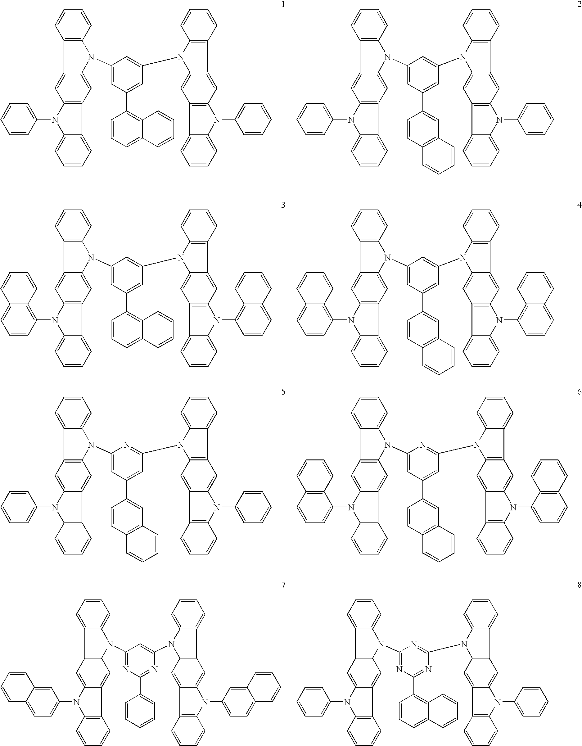
- a compound for an organic electroluminescent device according to this invention is represented by the following general formula (I).
- ring a is an aromatic or heterocyclic ring condensed with two adjacent rings and represented by formula (a1) or (a2)
- ring a′ is an aromatic or heterocyclic ring condensed with three adjacent rings and represented by formula (a1)
- X is CH or N
- ring b is a heterocyclic ring condensed with two adjacent rings and represented by formula (b1)
- Ar is a trivalent aromatic hydrocarbon group or a trivalent aromatic heterocyclic group
- L is independently a substituted or unsubstituted aromatic hydrocarbon group or a substituted or unsubstituted aromatic heterocyclic group and at least one has a condensed ring structure
- R is independently a hydrogen, an alkyl group, an aralkyl group, an alkenyl group, an alkynyl group, a cyano group, a dialkylamino group, a diarylamino group, a diaralkylamino group, an amino group, a nitro group, an
- the compounds for an organic electroluminescent device represented by general formula (I) include the compounds represented by the following general formula (II) or (III).
- Ring b′ is independently a heterocyclic ring condensed with two adjacent rings and represented by formula (b1).
- the group Ar in general formula (II) or (III) is preferably a trivalent group represented by the following general formula (IV);
- Y is independently CH or nitrogen (N) and at least one is N.
- this invention relates to an organic electroluminescent device wherein a light-emitting layer is disposed between an anode and a cathode piled one upon another on a substrate and said light-emitting layer comprises a phosphorescent dopant and the aforementioned compound for an organic electroluminescent device as a host material.
- the aforementioned organic electroluminescent device preferably has a hole-injecting/transporting layer disposed between the anode and the light-emitting layer and an electron-injecting/transporting layer disposed between the cathode and the light-emitting layer; moreover, it preferably has a hole-blocking layer disposed between the light-emitting layer and the electron-injecting/transporting layer.
- a compound for an organic electroluminescent device is represented by the aforementioned general formula (I).
- Preferable examples of the compounds represented by general formula (I) include the compounds represented by general formulas (II) and (III).
- the group Ar in general formulas (II) and (III) is preferably a trivalent group represented by general formula (IV).
- ring a is an aromatic or heterocyclic ring condensed with two adjacent rings and represented by formula (a1) or (a2)
- ring a′ is an aromatic or heterocyclic ring condensed with three adjacent rings and represented by formula (a1)
- X is CH or N
- ring b is a heterocyclic ring condensed with two adjacent rings and represented by formula (b1).
- Preferable examples of these rings can be understood from general formulas (II) and (III).
- the group Ar is a trivalent aromatic hydrocarbon group or a trivalent aromatic heterocyclic group.
- At least one valence for bonding must be on the aromatic hydrocarbon group or aromatic heterocyclic group and the rest may be on a group or an atom linking the aromatic hydrocarbon group or aromatic heterocyclic group.
- Ar are benzene rings or aromatic heterocyclic rings containing hetero atoms and more preferable examples are represented by general formula (IV).
- the group L is independently a substituted or unsubstituted aromatic hydrocarbon group or a substituted or unsubstituted aromatic heterocyclic group and at least one has a condensed ring structure.
- Such condensed rings include aromatic hydrocarbon rings or aromatic heterocyclic rings formed by condensation of 2 to 3 aromatic hydrocarbon rings or aromatic heterocyclic rings.
- the aromatic hydrocarbon groups or aromatic heterocyclic groups have substituents, preferable examples of the substituent include a group such as R to be described below.
- the group R is independently a hydrogen, an alkyl group, an aralkyl group, an alkenyl group, an alkynyl group, a cyano group, a dialkylamino group, a diarylamino group, a diaralkylamino group, an amino group, a nitro group, an acyl group, an alkoxycarbonyl group, a carboxyl group, an alkoxyl group, an alkylsulfonyl group, a haloalkyl group, a hydroxyl group, an amide group, a substituted or unsubstituted aromatic hydrocarbon group, or a substituted or unsubstituted aromatic heterocyclic group.
- Preferred is a hydrogen.
- R is an alkyl group, an alkoxyl group, an alkylsulfonyl group, a haloalkyl group, or an alkoxycarbonyl group
- the number of carbons in R is preferably 1 to 6.
- the number of carbons in R is preferably 2 to 6.
- the number of carbons in R is preferably 2 to 16.
- the rings or substituents located symmetrically on the opposite sides of Ar are identical with each other.
- ring a and ring b in one substituent are respectively identical with ring a and ring b in another substituent.
- two substituents located symmetrically about Ar in general formulas (II) and (III) it is advantageous that three Rs and two Ls in one substitutent are respectively identical with those in another substituent.
- the compounds represented by general formulas (I) to (III) can be prepared readily by a known method.
- the compounds represented by general formula (I) can be prepared by following a synthetic example described in Tetrahedron, 1991, Vol. 47, No. 37, pp. 7739-7750.
- the group Ar in general formulas (I) to (III) is a trivalent group which consisting of an L-substituted aromatic hydrocarbon or aromatic heterocyclic group and preferable examples of Ar include Ar-1 to Ar-20 shown below. In these examples, one valence is bonded to L while two are bonded to the ring nitrogen atoms.
- the substituent L is a substituted or unsubstituted aromatic hydrocarbon group or a substituted or unsubstituted aromatic heterocyclic group and preferably has a condensed ring structure.
- Preferable examples of L include L-1 to L-15 shown below. More preferable are L-2 to L-15.
- the organic EL device of this invention has at least one light-emitting layer disposed between an anode and a cathode piled one upon another on a substrate and said light-emitting layer comprises a phosphorescent dopant and the aforementioned compound for an organic EL device represented by any of general formulas (I) to (III) as a host material. It is preferable that a hole injecting/transporting layer is disposed between the anode and the light-emitting layer and an electron injecting/transporting layer is disposed between the cathode and the light-emitting layer. It is also preferable that a hole-blocking layer is disposed between the light-emitting layer and the electron injecting/transporting layer.
- Phosphorescent dopants to be used in the light-emitting layer are preferably organic metal complexes containing at least one metal selected from ruthenium, rhodium, palladium, silver, rhenium, osmium, iridium, platinum, and gold.
- organic metal complexes are known in the aforementioned patent documents and elsewhere and a suitable complex can be selected from them and used in this invention.
- Preferable phosphorescent dopants include complexes having a noble metal element such as Ir in the center, typically Ir(ppy)3, complexes such as Ir(bt)2.acac3, and complexes such as PtOEt3. Examples of these complexes are shown below, but are not limited thereto.
- the content of the aforementioned phosphorescent dopant in the light-emitting layer is preferably in the range of 5 to 10 wt %.
- FIG. 1 schematically shows the cross section of an example of an organic EL device.
- FIG. 1 schematically shows the structure of an example of an organic EL device generally used in this invention and 1 stands for a substrate, 2 for an anode, 3 for a hole-injecting layer, 4 for a hole-transporting layer, 5 for a light-emitting layer, 6 for an electron-transporting layer, and 7 for a cathode.
- the organic EL device of this invention comprises the substrate, the anode, the light-emitting layer, and the cathode as essential layers; in addition to the essential layers, the device preferably has a hole-injecting/transporting layer and an electron-injecting/transporting layer and, further, has a hole-blocking layer disposed between the light-emitting layer and the electron-injecting/transporting layer.
- the term hole-injecting/transporting layer means a hole-injecting layer and/or a hole-transporting layer and the term electron-injecting/transporting layer means an electron-injecting layer and/or an electron-transporting layer
- the organic EL device of this invention is applicable to a single device, a device with its structure arranged in array, or a device in which the anode and the cathode are arranged in X-Y matrix.
- the organic EL device of this invention produces remarkable improvements in luminous efficiency and driving stability over the conventional devices utilizing emission of light from the excited singlet state by incorporating a compound of specific skeleton and a phosphorescent dopant in its light-emitting layer and the device can perform excellently when applied to full-color or multicolor panels.
- the filtrate was transferred to a 2,000-ml separatory funnel and separated into an organic layer and an aqueous layer.
- the organic layer was washed three times with 500 ml of water and then dehydrated over magnesium sulfate, the magnesium sulfate was filtered out, and the solvent was distilled off under reduced pressure.
- the residue was purified by column chromatography to give 13.7 g (0.04 mole, 40.8% yield) of a white powder B.
- Compound 17 gave a fragment (M+1) with a mass of 868 in an analysis by EI-MS and showed a melting point of 398° C.
- Copper phthalocyanine (CuPC), ⁇ -NPD, and Alq3 were used respectively to form a hole-injecting layer, a hole-transporting layer, and an electron-transporting layer. They were deposited in thin films one upon another on a glass substrate having a 150 nm-thick ITO anode formed thereon by the vacuum deposition process at a degree of vacuum of 5.0 ⁇ 10 ⁇ 4 Pa. First, CuPC was deposited on the ITO anode to a thickness of 25 nm at a rate of 3.0 ⁇ /sec as a hole-injecting layer. Then, ⁇ -NPD was deposited on the hole-injecting layer to a thickness of 55 nm at a rate of 3.0 ⁇ /sec as a hole-transporting layer.
- Compound 17 and (Btp)2lracac (Compound 41 illustrated in the specification) were co-deposited on the hole-transporting layer from different evaporation sources to a thickness of 47.5 nm as a light-emitting layer.
- the concentration of (Btp)2Iracac at this time was 8.0%.
- Alq3 was deposited to a thickness of 30 nm at a rate of 3.0 ⁇ /sec as an electron-transporting layer.
- lithium fluoride (LiF) was deposited on the electron-transporting layer to a thickness of 1 nm at a rate of 0.1 ⁇ /sec as an electron-injecting layer.
- aluminum (Al) as an electrode was deposited on the electron-injecting layer to a thickness of 200 nm at a rate of 10 ⁇ /sec to complete the fabrication of an organic EL device.
- the ice bath was removed, 200 ml of toluene was thrown in, and the mixture was separated into an organic layer and an aqueous layer in a 1,000-ml separatory funnel.
- the organic layer was washed three times with 150 ml of water and then dehydrated over magnesium sulfate, the magnesium sulfate was filtered out, the solvent was distilled off under reduced pressure, and the remaining concentrate was recrystallized from hexane to give 61.6 g (0.272 mole, 71.7% yield) of light brown crystals.
- An organic EL device was fabricated as in Example 2 with the exception of using Compound 27 in place of Compound 17 as a host material of the light-emitting layer.
- An organic EL device was fabricated as in Example 2 with the exception of using BAlq in place of Compound 17 as a host material of the light-emitting layer.
- the peak wavelength of emitted light, maximum luminous efficiency, and luminance half life (initial luminance, 2,000 cd/m 2 ) of the organic EL devices fabricated in the examples and the comparative example are shown in Table 1.
- the organic EL device of this invention can emit light of high luminance at high efficiency with application of low voltage.
- the organic EL device of this invention is applicable to flat panel displays (for example, office computers and wall-hanging television sets), vehicle display devices, cellular phone displays, light sources utilizing the characteristics of planar light emitters (for example, light sources of copiers and backlight sources of liquid crystal displays and instruments), signboards, and beacon lights and has a high technical value.
Abstract
Description
-
- Patent document 1: JP2003-515897 A
- Patent document 2: JP2001-313178 A
- Patent document 3: JP2002-305083 A
- Patent document 4: JP2002-352957 A
- Patent document 5: JPH11-162650 A
- Patent document 6: JPH11-176578 A
- Patent document 7: JP2003-142264 A


wherein Y is independently CH or nitrogen (N) and at least one is N.


| TABLE 1 | ||||
| Peak wavelength | Maximum luminous | Luminance | ||
| of emitted light | efficiency | half life | ||
| (nm) | (cd/A) | (hr) | ||
| Example 2 | 620 | 9.2 | 3000 |
| Example 4 | 620 | 9.1 | 2500 |
| Comparative | 620 | 8.8 | 1500 |
| example 1 | |||
Claims (6)


Applications Claiming Priority (3)
| Application Number | Priority Date | Filing Date | Title |
|---|---|---|---|
| JP2007-142994 | 2007-05-30 | ||
| JP2007142994 | 2007-05-30 | ||
| PCT/JP2008/059523 WO2008149691A1 (en) | 2007-05-30 | 2008-05-23 | Compound for organic electroluminescent device and organic electroluminescent device |
Publications (2)
| Publication Number | Publication Date |
|---|---|
| US20100148162A1 US20100148162A1 (en) | 2010-06-17 |
| US8013330B2 true US8013330B2 (en) | 2011-09-06 |
Family
ID=40093515
Family Applications (1)
| Application Number | Title | Priority Date | Filing Date |
|---|---|---|---|
| US12/600,781 Active 2028-05-28 US8013330B2 (en) | 2007-05-30 | 2008-05-23 | Compound for organic electroluminescent device and organic electroluminescent device |
Country Status (7)
| Country | Link |
|---|---|
| US (1) | US8013330B2 (en) |
| EP (1) | EP2169029A4 (en) |
| JP (1) | JP4519946B2 (en) |
| KR (1) | KR101005160B1 (en) |
| CN (1) | CN101679852B (en) |
| TW (1) | TWI457416B (en) |
| WO (1) | WO2008149691A1 (en) |
Cited By (3)
| Publication number | Priority date | Publication date | Assignee | Title |
|---|---|---|---|---|
| US20120241732A1 (en) * | 2009-12-07 | 2012-09-27 | Ayataka Endo | Organic light-emitting material and organic light-emitting element |
| US9564600B2 (en) | 2011-02-22 | 2017-02-07 | Hodogaya Chemical Co., Ltd. | Compound having an indolocarbazole ring structure and organic electroluminescent device |
| US10186668B2 (en) | 2017-03-04 | 2019-01-22 | Feng-wen Yen | Organic electroluminescent material and use thereof |
Families Citing this family (42)
| Publication number | Priority date | Publication date | Assignee | Title |
|---|---|---|---|---|
| TWI468489B (en) * | 2007-05-29 | 2015-01-11 | Nippon Steel & Sumikin Chem Co | Organic electroluminescent element compounds and organic electroluminescent elements |
| WO2009148015A1 (en) * | 2008-06-05 | 2009-12-10 | 出光興産株式会社 | Halogen compound, polycyclic compound, and organic electroluminescence element comprising the polycyclic compound |
| US8049411B2 (en) | 2008-06-05 | 2011-11-01 | Idemitsu Kosan Co., Ltd. | Material for organic electroluminescence device and organic electroluminescence device using the same |
| DE102008064200A1 (en) * | 2008-12-22 | 2010-07-01 | Merck Patent Gmbh | Organic electroluminescent device |
| WO2010098246A1 (en) * | 2009-02-27 | 2010-09-02 | 新日鐵化学株式会社 | Organic electroluminescent element |
| US8759818B2 (en) | 2009-02-27 | 2014-06-24 | E I Du Pont De Nemours And Company | Deuterated compounds for electronic applications |
| KR101511072B1 (en) * | 2009-03-20 | 2015-04-10 | 롬엔드하스전자재료코리아유한회사 | Novel organic electroluminescent compounds and organic electroluminescent device using the same |
| TWI471405B (en) * | 2009-03-31 | 2015-02-01 | Nippon Steel & Sumikin Chem Co | A phosphorescent element material, and an organic electroluminescent device using the same |
| CN102362551B (en) * | 2009-03-31 | 2016-03-23 | 新日铁住金化学株式会社 | Organic electroluminescent device |
| KR101582707B1 (en) * | 2009-04-03 | 2016-01-05 | 이 아이 듀폰 디 네모아 앤드 캄파니 | Electroactive materials |
| DE102009031021A1 (en) | 2009-06-30 | 2011-01-05 | Merck Patent Gmbh | Materials for organic electroluminescent devices |
| JP5457907B2 (en) | 2009-08-31 | 2014-04-02 | ユー・ディー・シー アイルランド リミテッド | Organic electroluminescence device |
| JP4564584B1 (en) * | 2009-08-31 | 2010-10-20 | 富士フイルム株式会社 | Organic electroluminescence device |
| WO2011040939A1 (en) * | 2009-09-29 | 2011-04-07 | E. I. Du Pont De Nemours And Company | Deuterated compounds for luminescent applications |
| EP2493887A4 (en) | 2009-10-29 | 2013-06-19 | Du Pont | Deuterated compounds for electronic applications |
| DE102009052428A1 (en) | 2009-11-10 | 2011-05-12 | Merck Patent Gmbh | Connection for electronic devices |
| JP5897472B2 (en) | 2009-12-22 | 2016-03-30 | メルク パテント ゲーエムベーハー | Electroluminescent functional surfactant |
| EP2517275B1 (en) | 2009-12-22 | 2018-11-07 | Merck Patent GmbH | Formulations comprising phase-separated functional materials |
| WO2011076314A1 (en) | 2009-12-22 | 2011-06-30 | Merck Patent Gmbh | Electroluminescent formulations |
| EP2521196B1 (en) * | 2009-12-28 | 2018-09-12 | Nippon Steel & Sumikin Chemical Co., Ltd. | Organic electroluminescent element |
| DE102010009193B4 (en) | 2010-02-24 | 2022-05-19 | MERCK Patent Gesellschaft mit beschränkter Haftung | Composition containing fluorine-fluorine associates, processes for their production, their use and organic electronic devices containing them |
| EP2545600A2 (en) | 2010-03-11 | 2013-01-16 | Merck Patent GmbH | Radiative fibers |
| JP6246468B2 (en) | 2010-03-11 | 2017-12-13 | メルク パテント ゲーエムベーハー | Fiber in therapy and cosmetics |
| JP5577122B2 (en) * | 2010-03-18 | 2014-08-20 | 新日鉄住金化学株式会社 | Organic electroluminescence device |
| WO2011147522A1 (en) | 2010-05-27 | 2011-12-01 | Merck Patent Gmbh | Compositions comprising quantum dots |
| JP2013539584A (en) | 2010-07-26 | 2013-10-24 | メルク パテント ゲーエムベーハー | Quantum dots and hosts |
| US20130226268A1 (en) | 2010-07-26 | 2013-08-29 | Merck Patent Gmbh | Nanocrystals in devices |
| JP5727038B2 (en) | 2010-12-20 | 2015-06-03 | イー・アイ・デュポン・ドウ・ヌムール・アンド・カンパニーE.I.Du Pont De Nemours And Company | Compositions for electronic technology applications |
| JP5756288B2 (en) * | 2010-12-28 | 2015-07-29 | 出光興産株式会社 | Fused polycyclic compound, material for organic electroluminescence device, and organic electroluminescence device using the same |
| WO2012110178A1 (en) | 2011-02-14 | 2012-08-23 | Merck Patent Gmbh | Device and method for treatment of cells and cell tissue |
| JP6356060B2 (en) | 2011-03-24 | 2018-07-11 | メルク パテント ゲーエムベーハー | Organic ionic functional materials |
| WO2012149992A1 (en) | 2011-05-04 | 2012-11-08 | Merck Patent Gmbh | Device for preserving fresh goods |
| US9496502B2 (en) | 2011-05-12 | 2016-11-15 | Merck Patent Gmbh | Organic ionic compounds, compositions and electronic devices |
| KR20140123555A (en) | 2012-01-30 | 2014-10-22 | 메르크 파텐트 게엠베하 | Nanocrystals on fibers |
| TWI599570B (en) * | 2012-09-28 | 2017-09-21 | 新日鐵住金化學股份有限公司 | Compounds for organic electroluminescent devices and organic electroluminescent devices |
| JP6436901B2 (en) * | 2013-02-28 | 2018-12-12 | 日鉄ケミカル&マテリアル株式会社 | Boron compound for organic electroluminescence device and organic electroluminescence device |
| KR101835502B1 (en) * | 2014-07-21 | 2018-03-07 | 삼성에스디아이 주식회사 | Composition for organic optoelectric device and organic optoelectric device and display device |
| WO2017092473A1 (en) * | 2015-12-04 | 2017-06-08 | 广州华睿光电材料有限公司 | Compound with connected indole heterocycles and use thereof in organic electronic device |
| KR20230002860A (en) | 2020-04-21 | 2023-01-05 | 메르크 파텐트 게엠베하 | Emulsion containing organic functional materials |
| CN114105997B (en) * | 2021-01-28 | 2023-05-19 | 陕西莱特光电材料股份有限公司 | Nitrogen-containing compound, and electronic element and electronic device comprising same |
| CN117730638A (en) | 2021-08-02 | 2024-03-19 | 默克专利有限公司 | Printing method by combining inks |
| WO2023237458A1 (en) | 2022-06-07 | 2023-12-14 | Merck Patent Gmbh | Method of printing a functional layer of an electronic device by combining inks |
Citations (19)
| Publication number | Priority date | Publication date | Assignee | Title |
|---|---|---|---|---|
| JPH11144866A (en) | 1997-11-05 | 1999-05-28 | Toray Ind Inc | Electroluminescent element |
| JPH11162650A (en) | 1997-10-02 | 1999-06-18 | Xerox Corp | Electroluminescent device |
| JPH11176578A (en) | 1997-10-02 | 1999-07-02 | Xerox Corp | Electroluminescent device using indolo carbazole |
| US20010052751A1 (en) | 2000-02-23 | 2001-12-20 | Takeo Wakimoto | Organic electroluminescence element |
| US20020135296A1 (en) | 2001-01-26 | 2002-09-26 | Xerox Corporation | Organic light emitting devices |
| JP2002305083A (en) | 2001-04-04 | 2002-10-18 | Mitsubishi Chemicals Corp | Organic electroluminescent element |
| JP2002352957A (en) | 2001-05-23 | 2002-12-06 | Honda Motor Co Ltd | Organic electoluminescence element |
| JP2003515897A (en) | 1999-12-01 | 2003-05-07 | ザ、トラスティーズ オブ プリンストン ユニバーシティ | Complexes of Formula L2MX as phosphorescent dopants for organic LEDs |
| US20030205696A1 (en) | 2002-04-25 | 2003-11-06 | Canon Kabushiki Kaisha | Carbazole-based materials for guest-host electroluminescent systems |
| US6670054B1 (en) | 2002-07-25 | 2003-12-30 | Xerox Corporation | Electroluminescent devices |
| US20040137271A1 (en) | 2002-12-24 | 2004-07-15 | Byung-Hee Sohn | Blue electroluminescent polymer and organo-electroluminescent device employing the same |
| JP2005174917A (en) | 2003-11-21 | 2005-06-30 | Canon Inc | Organic light emitting element, organic compound, and display device |
| JP2005213188A (en) | 2004-01-29 | 2005-08-11 | Mitsubishi Chemicals Corp | Compound, charge transport material, organic electroluminescent element material and organic electroluminescent element |
| JP2006013469A (en) | 2004-05-25 | 2006-01-12 | Mitsubishi Chemicals Corp | Charge transporting material, laminate, and organic electroluminescent element |
| WO2006033538A1 (en) | 2004-09-20 | 2006-03-30 | Lg Chem. Ltd. | Carbazole derivative and organic light emitting device using same |
| WO2007063754A1 (en) | 2005-12-01 | 2007-06-07 | Nippon Steel Chemical Co., Ltd. | Compound for organic electroluminescent element and organic electroluminescent element |
| WO2007063796A1 (en) | 2005-12-01 | 2007-06-07 | Nippon Steel Chemical Co., Ltd. | Organic electroluminescent device |
| US7291406B2 (en) | 1999-03-23 | 2007-11-06 | The Trustees Of Princeton University | Organometallic complexes as phosphorescent emitters in organic LEDS |
| WO2008056746A1 (en) | 2006-11-09 | 2008-05-15 | Nippon Steel Chemical Co., Ltd. | Compound for organic electroluminescent device and organic electroluminescent device |
Family Cites Families (3)
| Publication number | Priority date | Publication date | Assignee | Title |
|---|---|---|---|---|
| JP2001313178A (en) | 2000-04-28 | 2001-11-09 | Pioneer Electronic Corp | Organic electroluminescent element |
| JP4011325B2 (en) | 2001-10-31 | 2007-11-21 | パイオニア株式会社 | Organic electroluminescence device |
| TWI468489B (en) * | 2007-05-29 | 2015-01-11 | Nippon Steel & Sumikin Chem Co | Organic electroluminescent element compounds and organic electroluminescent elements |
-
2008
- 2008-05-23 WO PCT/JP2008/059523 patent/WO2008149691A1/en active Application Filing
- 2008-05-23 KR KR1020097025726A patent/KR101005160B1/en active IP Right Grant
- 2008-05-23 JP JP2009517791A patent/JP4519946B2/en active Active
- 2008-05-23 EP EP08764569.3A patent/EP2169029A4/en not_active Withdrawn
- 2008-05-23 US US12/600,781 patent/US8013330B2/en active Active
- 2008-05-23 CN CN2008800150745A patent/CN101679852B/en active Active
- 2008-05-29 TW TW097119920A patent/TWI457416B/en not_active IP Right Cessation
Patent Citations (27)
| Publication number | Priority date | Publication date | Assignee | Title |
|---|---|---|---|---|
| JPH11162650A (en) | 1997-10-02 | 1999-06-18 | Xerox Corp | Electroluminescent device |
| JPH11176578A (en) | 1997-10-02 | 1999-07-02 | Xerox Corp | Electroluminescent device using indolo carbazole |
| US5942340A (en) | 1997-10-02 | 1999-08-24 | Xerox Corporation | Indolocarbazole electroluminescent devices |
| US5952115A (en) | 1997-10-02 | 1999-09-14 | Xerox Corporation | Electroluminescent devices |
| JPH11144866A (en) | 1997-11-05 | 1999-05-28 | Toray Ind Inc | Electroluminescent element |
| US7291406B2 (en) | 1999-03-23 | 2007-11-06 | The Trustees Of Princeton University | Organometallic complexes as phosphorescent emitters in organic LEDS |
| JP2003515897A (en) | 1999-12-01 | 2003-05-07 | ザ、トラスティーズ オブ プリンストン ユニバーシティ | Complexes of Formula L2MX as phosphorescent dopants for organic LEDs |
| US20010052751A1 (en) | 2000-02-23 | 2001-12-20 | Takeo Wakimoto | Organic electroluminescence element |
| US20020135296A1 (en) | 2001-01-26 | 2002-09-26 | Xerox Corporation | Organic light emitting devices |
| JP2002305083A (en) | 2001-04-04 | 2002-10-18 | Mitsubishi Chemicals Corp | Organic electroluminescent element |
| JP2002352957A (en) | 2001-05-23 | 2002-12-06 | Honda Motor Co Ltd | Organic electoluminescence element |
| US20030205696A1 (en) | 2002-04-25 | 2003-11-06 | Canon Kabushiki Kaisha | Carbazole-based materials for guest-host electroluminescent systems |
| US6670054B1 (en) | 2002-07-25 | 2003-12-30 | Xerox Corporation | Electroluminescent devices |
| US20040137271A1 (en) | 2002-12-24 | 2004-07-15 | Byung-Hee Sohn | Blue electroluminescent polymer and organo-electroluminescent device employing the same |
| JP2004204234A (en) | 2002-12-24 | 2004-07-22 | Samsung Sdi Co Ltd | Blue light-emitting polymer and organic el element using the same |
| US7172823B2 (en) | 2002-12-24 | 2007-02-06 | Samsung Sdi Co., Ltd. | Blue electroluminescent polymer and organo-electroluminescent device employing the same |
| US20070057250A1 (en) | 2003-11-21 | 2007-03-15 | Canon Kabushiki Kaisha | Light-emitting device, organic compound and display |
| JP2005174917A (en) | 2003-11-21 | 2005-06-30 | Canon Inc | Organic light emitting element, organic compound, and display device |
| JP2005213188A (en) | 2004-01-29 | 2005-08-11 | Mitsubishi Chemicals Corp | Compound, charge transport material, organic electroluminescent element material and organic electroluminescent element |
| JP2006013469A (en) | 2004-05-25 | 2006-01-12 | Mitsubishi Chemicals Corp | Charge transporting material, laminate, and organic electroluminescent element |
| WO2006033538A1 (en) | 2004-09-20 | 2006-03-30 | Lg Chem. Ltd. | Carbazole derivative and organic light emitting device using same |
| WO2007063754A1 (en) | 2005-12-01 | 2007-06-07 | Nippon Steel Chemical Co., Ltd. | Compound for organic electroluminescent element and organic electroluminescent element |
| WO2007063796A1 (en) | 2005-12-01 | 2007-06-07 | Nippon Steel Chemical Co., Ltd. | Organic electroluminescent device |
| EP1956022A1 (en) | 2005-12-01 | 2008-08-13 | Nippon Steel Chemical Co., Ltd. | Compound for organic electroluminescent element and organic electroluminescent element |
| EP1956666A1 (en) | 2005-12-01 | 2008-08-13 | Nippon Steel Chemical Co., Ltd. | Organic electroluminescent device |
| WO2008056746A1 (en) | 2006-11-09 | 2008-05-15 | Nippon Steel Chemical Co., Ltd. | Compound for organic electroluminescent device and organic electroluminescent device |
| EP2080762A1 (en) | 2006-11-09 | 2009-07-22 | Nippon Steel Chemical Co., Ltd. | Compound for organic electroluminescent device and organic electroluminescent device |
Non-Patent Citations (2)
| Title |
|---|
| Office Action in U.S. Appl. No. 12/085,447, mailed Sep. 23, 2010. |
| PCT/JP2006/323290-English translation of International Preliminary Report on Patentability and Written Opinion of the International Searching Authority (Forms PCT/IB/373, PCT/IB/338, PCT/IB/326, and PCT/ISA/237) dated Jun. 12, 2008. |
Cited By (4)
| Publication number | Priority date | Publication date | Assignee | Title |
|---|---|---|---|---|
| US20120241732A1 (en) * | 2009-12-07 | 2012-09-27 | Ayataka Endo | Organic light-emitting material and organic light-emitting element |
| US8993129B2 (en) * | 2009-12-07 | 2015-03-31 | Nippon Steel & Sumikin Chemical Co., Ltd. | Fluorescence and delayed fluorescence-type organic light-emitting material and element |
| US9564600B2 (en) | 2011-02-22 | 2017-02-07 | Hodogaya Chemical Co., Ltd. | Compound having an indolocarbazole ring structure and organic electroluminescent device |
| US10186668B2 (en) | 2017-03-04 | 2019-01-22 | Feng-wen Yen | Organic electroluminescent material and use thereof |
Also Published As
| Publication number | Publication date |
|---|---|
| KR101005160B1 (en) | 2011-01-04 |
| JPWO2008149691A1 (en) | 2010-08-26 |
| KR20100017738A (en) | 2010-02-16 |
| WO2008149691A1 (en) | 2008-12-11 |
| EP2169029A4 (en) | 2013-05-29 |
| JP4519946B2 (en) | 2010-08-04 |
| EP2169029A1 (en) | 2010-03-31 |
| CN101679852B (en) | 2012-12-05 |
| CN101679852A (en) | 2010-03-24 |
| US20100148162A1 (en) | 2010-06-17 |
| TW200914578A (en) | 2009-04-01 |
| TWI457416B (en) | 2014-10-21 |
Similar Documents
| Publication | Publication Date | Title |
|---|---|---|
| US8013330B2 (en) | Compound for organic electroluminescent device and organic electroluminescent device | |
| US8008657B2 (en) | Compound for organic electroluminescent device and organic electroluminescent device | |
| US7993760B2 (en) | Compound for use in organic electroluminescent device and organic electroluminescent device | |
| US8062769B2 (en) | Indolocarbazole compound for use in organic electroluminescent device and organic electroluminescent device | |
| US8795848B2 (en) | Indolocarbazole derivative with fused heterocyclic aromatic group for organic electroluminescent device and organic electroluminescent device containing same | |
| US8703302B2 (en) | Indolocarbazole derivative with aromatic phosphne oxide group for organic electroluminescent device and organic electroluminescent device containing same | |
| US8758904B2 (en) | Organic electroluminescent device comprising a first electron-transporting layer and a second electron-transporting layer | |
| US8962158B2 (en) | Material having indolocarbazole compound for phosphorescent light-emitting element and organic electroluminescent element using the same | |
| EP2521196B1 (en) | Organic electroluminescent element | |
| US8906521B2 (en) | Organic electroluminescent device having triptycene derivative material | |
| US8815416B2 (en) | Organic electroluminescent device using a bipyrimidine compound | |
| US8859109B2 (en) | Compound for organic electroluminescent device and organic electroluminescent device using the same | |
| US7968874B2 (en) | Organic electroluminescent device material and organic electroluminescent device |
Legal Events
| Date | Code | Title | Description |
|---|---|---|---|
| AS | Assignment |
Owner name: NIPPON STEEL CHEMICAL CO., LTD.,JAPAN Free format text: ASSIGNMENT OF ASSIGNORS INTEREST;ASSIGNORS:KOMORI, MASAKI;YAMAMOTO, TOSHIHIRO;KAI, TAKAHIRO;AND OTHERS;REEL/FRAME:023630/0054 Effective date: 20090917 Owner name: NIPPON STEEL CHEMICAL CO., LTD., JAPAN Free format text: ASSIGNMENT OF ASSIGNORS INTEREST;ASSIGNORS:KOMORI, MASAKI;YAMAMOTO, TOSHIHIRO;KAI, TAKAHIRO;AND OTHERS;REEL/FRAME:023630/0054 Effective date: 20090917 |
|
| STCF | Information on status: patent grant |
Free format text: PATENTED CASE |
|
| AS | Assignment |
Owner name: NIPPON STEEL & SUMIKIN CHEMICAL CO., LTD., JAPAN Free format text: CHANGE OF NAME;ASSIGNOR:NIPPON STEEL CHEMICAL CO., LTD.;REEL/FRAME:030049/0771 Effective date: 20121001 |
|
| FPAY | Fee payment |
Year of fee payment: 4 |
|
| MAFP | Maintenance fee payment |
Free format text: PAYMENT OF MAINTENANCE FEE, 8TH YEAR, LARGE ENTITY (ORIGINAL EVENT CODE: M1552); ENTITY STATUS OF PATENT OWNER: LARGE ENTITY Year of fee payment: 8 |
|
| AS | Assignment |
Owner name: NIPPON STEEL CHEMICAL & MATERIAL CO., LTD., JAPAN Free format text: MERGER;ASSIGNORS:NIPPON STEEL & SUMIKIN MATERIALS CO., LTD.;NIPPON STEEL & SUMIKIN CHEMICAL CO., LTD.;REEL/FRAME:054145/0400 Effective date: 20181002 |
|
| MAFP | Maintenance fee payment |
Free format text: PAYMENT OF MAINTENANCE FEE, 12TH YEAR, LARGE ENTITY (ORIGINAL EVENT CODE: M1553); ENTITY STATUS OF PATENT OWNER: LARGE ENTITY Year of fee payment: 12 |