US8013741B2 - Evidence tracking - Google Patents
Evidence tracking Download PDFInfo
- Publication number
- US8013741B2 US8013741B2 US13/004,176 US201113004176A US8013741B2 US 8013741 B2 US8013741 B2 US 8013741B2 US 201113004176 A US201113004176 A US 201113004176A US 8013741 B2 US8013741 B2 US 8013741B2
- Authority
- US
- United States
- Prior art keywords
- transceiver
- tag
- scene
- crime scene
- evidence
- Prior art date
- Legal status (The legal status is an assumption and is not a legal conclusion. Google has not performed a legal analysis and makes no representation as to the accuracy of the status listed.)
- Expired - Fee Related
Links
Images

Classifications
-
- G—PHYSICS
- G06—COMPUTING; CALCULATING OR COUNTING
- G06K—GRAPHICAL DATA READING; PRESENTATION OF DATA; RECORD CARRIERS; HANDLING RECORD CARRIERS
- G06K17/00—Methods or arrangements for effecting co-operative working between equipments covered by two or more of main groups G06K1/00 - G06K15/00, e.g. automatic card files incorporating conveying and reading operations
Definitions
- RFID tags for example, to try to keep track of evidence and to assist in logging entry and exit of personnel from areas.
- Most RFID tag designs are not very workable for these purposes, as they are little more than high-tech bar codes that can only be read by a reader such as a handheld “gun” that is placed into close physical proximity with a tag to read the tag.
- close-proximity readers whether bar-code or RFID.
- an evidence bag might enter or exit a crime scene boundary at any point along the boundary.
- a system uses a large loop antenna, connected with a transceiver operating below 1 MHz.
- the loop antenna is deployed from a spool to surround a crime scene, and may carry indicia communicating that it is a crime scene boundary.
- the system interrogates devices, including evidence bags and badged personnel, as they enter and leave the scene.
- the system can optionally log the time of salient events.
- a second loop antenna can log evidence bags as they enter a vehicle.
- the devices can be silenced by the transceiver and thus collisions can be reduced and avoided among responses from devices.
- the system performs “area reads” that would not be possible if higher RF frequencies were employed.
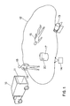
- FIG. 1 shows a typical deployment of the system according to the invention.
- FIG. 1 what is shown is a typical deployment of the system according to the invention.
- a truck or other motor vehicle 16 arrives at a crime scene defined by corpse 15 .
- a spool 13 is removed from the truck and is placed at a position that lies on a desired crime scene boundary.
- An electrically conductive line 12 is unspooled from the spool 13 and is laid out along the surface of the ground along the desired crime scene boundary, returning to the start to define a complete boundary.
- the line is connected to a transceiver 14 about which more will be said later.
- the transceiver 14 is optionally equipped with a GPRS, Edge, EVDO, WiFi, or other WAN interface permitting reporting of events to distant equipment omitted for clarity in FIG. 1 .
- Radio tags employed can, for example, be tags such as those described in U.S. Pat. No. 7,049,963 entitled “Networked RF tag for tracking freight” and assigned to the same assignee as the present invention, which patent is incorporated herein by reference.
- the transceiver 14 can, for example, be a transceiver such as that described in copending U.S. application Ser. No. 60/806,520, filed Jul. 3, 2006 and assigned to the same assignee as the present invention, which application is incorporated herein by reference.
- the transceiver can transmit at, say, a predetermined multiple of 32768 Hertz (the standard watch crystal frequency) such as 65 kHz or 133 kHz.
- the transceiver may have switchable antenna terminals to handle as many as four distinct antennae. The transceiver can switch from one antenna to the next, and even if one antenna is not well coupled with a particular tag, very likely one of the other two antennas will turn out to be well coupled with that particular tag.
- Each tag whether on an evidence bag or on a badge, has a respective identifier and is disposed to receive queries at a radio frequency no greater than 1 MHz and to emit responses thereto at a radio frequency no greater than 1 MHz.
- an evidence bag there is a tag mechanically affixed to the bag.
- the bag has an opening and a closure for the opening.
- a first responder at the crime scene will define a first scene of interest having a perimeter, the scene of interest having an area, the area exceeding twenty-five square feet, the perimeter extending at least twenty feet.
- the conductive line is deployed starting with its first end at a first point at the perimeter, along the perimeter around the first scene of interest, and returning with its second end to the first point.
- a first apparatus (the transceiver 14 ) is connected a the first and second ends of the line. The apparatus operates at a radio frequency no greater than 1 MHz.
- the first apparatus is operated to emit a query. It is operated to listen for a response to the query from a tag. In the event of a response, an identifier is extracted an identifier, and the identifier is stored in the first apparatus and/or is communicated via a WAN link to other equipment. A silence request is transmitted with respect to the identifier.
- the emitting, listening, extracting, storing, and transmitting steps, are repeated, thereby accumulating a list of identifiers.
- the system makes note of times at which the list changes, thereby detecting events of tags and/or badges entering and leaving the first scene of interest.
- the line is removed and respooled. Still later, the spool is redeployed to a second crime scene elsewhere.
- the line may be laid upon the ground, or may be suspended from posts or vegetation or otherwise deployed at waist or chest height.
- Evidence bags can optionally each have a button that permits the tag to respond differently due to the pressing of the button, in which case in the event of a response that is different due to the pressing of a button, what is stored additionally includes information thereof, thereby detecting events of the pressing of a button on a tag.
- the button might mean that the bag has been put into use.
- the evidence bags may each have a motion sensor which, when triggered, causes the tag to respond differently due to sensed motion, in which case in the event of a response that is different due to sensed motion, what is stored additionally includes information thereof, thereby detecting events of motion of an evidence bag.
- the procedure for use of a bag may include such steps as placing a first item in a bag affixed to a first tag; closing the closure of the bag affixed to the first tag; placing a second item in a bag affixed to a second tag; closing the closure of the bag affixed to the second tag; removing the first tag and the second tag, and their respective bags, from the enclosure; and detecting the events of the first and second tags leaving the scene of interest.
- a badge may have a respective identifier and disposed to receive queries at a radio frequency no greater than 1 MHz and to emit responses thereto at a radio frequency no greater than 1 MHz, in which case the step of making note of times at which the list changes further detects events of badges entering and leaving the first scene of interest.
- the evidence bags may optionally each have a sensor sensing a closed condition of the closure, the sensor causing the tag to respond differently due to the closed condition, in which case in the event of a response that is different due to the closed condition, what is stored additionally includes information thereof, thereby detecting events of the closure being opened or closed on the bag of a tag.
- the conductive line may comprises a tape bearing printed indicia visible from a distance, for example the words “CRIME SCENE”.
- this system can detect entry and exit of evidence bags and of badges from any direction. There is not a need to enter and exit at a particular point along the boundary.
Abstract
Description
Claims (3)
Priority Applications (1)
| Application Number | Priority Date | Filing Date | Title |
|---|---|---|---|
| US13/004,176 US8013741B2 (en) | 2005-07-19 | 2011-01-11 | Evidence tracking |
Applications Claiming Priority (5)
| Application Number | Priority Date | Filing Date | Title |
|---|---|---|---|
| US70088605P | 2005-07-19 | 2005-07-19 | |
| US80674806P | 2006-07-07 | 2006-07-07 | |
| US11/456,182 US7436304B1 (en) | 2005-07-19 | 2006-07-07 | Evidence tracking |
| US12/249,639 US20090038191A1 (en) | 2005-07-19 | 2008-10-10 | Evidence Tracking |
| US13/004,176 US8013741B2 (en) | 2005-07-19 | 2011-01-11 | Evidence tracking |
Related Parent Applications (1)
| Application Number | Title | Priority Date | Filing Date |
|---|---|---|---|
| US12/249,639 Continuation US20090038191A1 (en) | 2005-07-19 | 2008-10-10 | Evidence Tracking |
Publications (2)
| Publication Number | Publication Date |
|---|---|
| US20110108321A1 US20110108321A1 (en) | 2011-05-12 |
| US8013741B2 true US8013741B2 (en) | 2011-09-06 |
Family
ID=37669199
Family Applications (3)
| Application Number | Title | Priority Date | Filing Date |
|---|---|---|---|
| US11/456,182 Expired - Fee Related US7436304B1 (en) | 2005-07-19 | 2006-07-07 | Evidence tracking |
| US12/249,639 Abandoned US20090038191A1 (en) | 2005-07-19 | 2008-10-10 | Evidence Tracking |
| US13/004,176 Expired - Fee Related US8013741B2 (en) | 2005-07-19 | 2011-01-11 | Evidence tracking |
Family Applications Before (2)
| Application Number | Title | Priority Date | Filing Date |
|---|---|---|---|
| US11/456,182 Expired - Fee Related US7436304B1 (en) | 2005-07-19 | 2006-07-07 | Evidence tracking |
| US12/249,639 Abandoned US20090038191A1 (en) | 2005-07-19 | 2008-10-10 | Evidence Tracking |
Country Status (4)
| Country | Link |
|---|---|
| US (3) | US7436304B1 (en) |
| EP (1) | EP1924955A4 (en) |
| CA (1) | CA2615883A1 (en) |
| WO (1) | WO2007010435A2 (en) |
Families Citing this family (3)
| Publication number | Priority date | Publication date | Assignee | Title |
|---|---|---|---|---|
| US7831066B2 (en) * | 2006-09-15 | 2010-11-09 | Robert William Kocher | Pocket identification collection kit (PICK) |
| ES2332846B1 (en) | 2007-10-26 | 2010-07-08 | Grifols, S.A. | USE OF THERAPEUTIC HUMAN ALBUMIN FOR THE PREPARATION OF A MEDICINAL PRODUCT FOR THE TREATMENT OF PATIENTS AFFECTED BY COGNITIVE DISORDERS. |
| KR100796531B1 (en) * | 2007-11-05 | 2008-01-21 | 신화엘컴주식회사 | Location management system for moving object and location management method for moving object |
Citations (21)
| Publication number | Priority date | Publication date | Assignee | Title |
|---|---|---|---|---|
| US4745882A (en) * | 1986-11-20 | 1988-05-24 | Yarnall Sr Robert G | Electronic confinement and communications arrangement for animals |
| US5272466A (en) * | 1991-11-20 | 1993-12-21 | Freedom Fence, Inc. | Method and apparatus for defining a perimeter |
| US5371982A (en) * | 1992-06-08 | 1994-12-13 | Hopkins International, Inc. | Portable area security enclosure kit |
| USD362797S (en) * | 1994-10-24 | 1995-10-03 | Ted Caracciolo | Crime scene tape caddy and tape therefor |
| US5781704A (en) | 1996-10-11 | 1998-07-14 | Environmental Criminology Research, Inc. | Expert system method of performing crime site analysis |
| US5893228A (en) * | 1997-06-30 | 1999-04-13 | Rivera; Luis M. | Sign for use in entrance of hazardous confined space |
| US20010040508A1 (en) * | 1997-10-23 | 2001-11-15 | Janning Joseph J. | Battery-powered RF signaling system and system for controlling the whereabouts of an animal using same |
| US20010045554A1 (en) * | 2000-01-20 | 2001-11-29 | Pulliam Bryan J. | Portable fencing system and components therefor |
| US6538623B1 (en) | 1999-05-13 | 2003-03-25 | Pirooz Parnian | Multi-media data collection tool kit having an electronic multi-media “case” file and method of use |
| US6750769B1 (en) | 2002-12-12 | 2004-06-15 | Sun Microsystems, Inc. | Method and apparatus for using RFID tags to determine the position of an object |
| US6772532B1 (en) * | 2000-05-27 | 2004-08-10 | Richard Honea | Disposable tape measure system |
| US6816075B2 (en) | 2001-02-21 | 2004-11-09 | 3M Innovative Properties Company | Evidence and property tracking for law enforcement |
| US20050008433A1 (en) * | 2003-07-10 | 2005-01-13 | Joe Dvoracek | Ring topped road delineator with sheltered tie-on terminal |
| US20050012619A1 (en) * | 2003-06-06 | 2005-01-20 | Sato Kimihiko Ernst | Large array of radio frequency ID transponders deployed in an array by use of deploying rows of transponders that unwind from long spools of high strength fibre or tape with passive RFID transponders separated by fixed lengths |
| US6935059B1 (en) * | 2004-05-22 | 2005-08-30 | Hungkun J. Chang | Crime scene fence post |
| US6992582B2 (en) | 2001-09-28 | 2006-01-31 | Satellite Tracking Of People Llc | System and method for tracking movement of individuals |
| US20060055559A1 (en) * | 2004-09-11 | 2006-03-16 | Leonard Charles R | Retractable lighted traffic control strip |
| US7013619B2 (en) | 2004-06-07 | 2006-03-21 | Clearwater Packaging, Inc. | Property and evidence preservation system |
| US7049963B2 (en) | 2003-04-09 | 2006-05-23 | Visible Assets, Inc. | Networked RF tag for tracking freight |
| US20060130598A1 (en) * | 2004-12-22 | 2006-06-22 | Driessche Cory V | Method and apparatus for collecting evidence |
| US20070085681A1 (en) | 2002-07-09 | 2007-04-19 | Fred Sawyer | Method and apparatus for tracking objects and people |
Family Cites Families (5)
| Publication number | Priority date | Publication date | Assignee | Title |
|---|---|---|---|---|
| US4091367A (en) * | 1974-02-28 | 1978-05-23 | Robert Keith Harman | Perimeter surveillance system |
| US4213122A (en) * | 1978-08-23 | 1980-07-15 | The United States Of America As Represented By The Secretary Of The Air Force | Intrusion detection system |
| CA2262895C (en) * | 1997-06-06 | 2008-04-01 | Auratek Security Inc. | Intrusion detection system using quiet signal band detection |
| WO2001061230A2 (en) * | 2000-02-17 | 2001-08-23 | Dixon Roche Keith | Fabrication of hoses or other elongated articles |
| US7488929B2 (en) * | 2003-08-13 | 2009-02-10 | Zygo Corporation | Perimeter detection using fiber optic sensors |
-
2006
- 2006-07-07 US US11/456,182 patent/US7436304B1/en not_active Expired - Fee Related
- 2006-07-11 EP EP06766064A patent/EP1924955A4/en not_active Withdrawn
- 2006-07-11 CA CA002615883A patent/CA2615883A1/en not_active Abandoned
- 2006-07-11 WO PCT/IB2006/052333 patent/WO2007010435A2/en active Application Filing
-
2008
- 2008-10-10 US US12/249,639 patent/US20090038191A1/en not_active Abandoned
-
2011
- 2011-01-11 US US13/004,176 patent/US8013741B2/en not_active Expired - Fee Related
Patent Citations (22)
| Publication number | Priority date | Publication date | Assignee | Title |
|---|---|---|---|---|
| US4745882A (en) * | 1986-11-20 | 1988-05-24 | Yarnall Sr Robert G | Electronic confinement and communications arrangement for animals |
| US5272466A (en) * | 1991-11-20 | 1993-12-21 | Freedom Fence, Inc. | Method and apparatus for defining a perimeter |
| US5371982A (en) * | 1992-06-08 | 1994-12-13 | Hopkins International, Inc. | Portable area security enclosure kit |
| USD362797S (en) * | 1994-10-24 | 1995-10-03 | Ted Caracciolo | Crime scene tape caddy and tape therefor |
| US5781704C1 (en) | 1996-10-11 | 2002-07-16 | Environmental Criminology Res | Expert system method of performing crime site analysis |
| US5781704A (en) | 1996-10-11 | 1998-07-14 | Environmental Criminology Research, Inc. | Expert system method of performing crime site analysis |
| US5893228A (en) * | 1997-06-30 | 1999-04-13 | Rivera; Luis M. | Sign for use in entrance of hazardous confined space |
| US20010040508A1 (en) * | 1997-10-23 | 2001-11-15 | Janning Joseph J. | Battery-powered RF signaling system and system for controlling the whereabouts of an animal using same |
| US6538623B1 (en) | 1999-05-13 | 2003-03-25 | Pirooz Parnian | Multi-media data collection tool kit having an electronic multi-media “case” file and method of use |
| US20010045554A1 (en) * | 2000-01-20 | 2001-11-29 | Pulliam Bryan J. | Portable fencing system and components therefor |
| US6772532B1 (en) * | 2000-05-27 | 2004-08-10 | Richard Honea | Disposable tape measure system |
| US6816075B2 (en) | 2001-02-21 | 2004-11-09 | 3M Innovative Properties Company | Evidence and property tracking for law enforcement |
| US6992582B2 (en) | 2001-09-28 | 2006-01-31 | Satellite Tracking Of People Llc | System and method for tracking movement of individuals |
| US20070085681A1 (en) | 2002-07-09 | 2007-04-19 | Fred Sawyer | Method and apparatus for tracking objects and people |
| US6750769B1 (en) | 2002-12-12 | 2004-06-15 | Sun Microsystems, Inc. | Method and apparatus for using RFID tags to determine the position of an object |
| US7049963B2 (en) | 2003-04-09 | 2006-05-23 | Visible Assets, Inc. | Networked RF tag for tracking freight |
| US20050012619A1 (en) * | 2003-06-06 | 2005-01-20 | Sato Kimihiko Ernst | Large array of radio frequency ID transponders deployed in an array by use of deploying rows of transponders that unwind from long spools of high strength fibre or tape with passive RFID transponders separated by fixed lengths |
| US20050008433A1 (en) * | 2003-07-10 | 2005-01-13 | Joe Dvoracek | Ring topped road delineator with sheltered tie-on terminal |
| US6935059B1 (en) * | 2004-05-22 | 2005-08-30 | Hungkun J. Chang | Crime scene fence post |
| US7013619B2 (en) | 2004-06-07 | 2006-03-21 | Clearwater Packaging, Inc. | Property and evidence preservation system |
| US20060055559A1 (en) * | 2004-09-11 | 2006-03-16 | Leonard Charles R | Retractable lighted traffic control strip |
| US20060130598A1 (en) * | 2004-12-22 | 2006-06-22 | Driessche Cory V | Method and apparatus for collecting evidence |
Also Published As
| Publication number | Publication date |
|---|---|
| WO2007010435A3 (en) | 2009-04-16 |
| WO2007010435A2 (en) | 2007-01-25 |
| EP1924955A2 (en) | 2008-05-28 |
| EP1924955A4 (en) | 2010-03-31 |
| US20110108321A1 (en) | 2011-05-12 |
| WO2007010435A8 (en) | 2007-03-15 |
| CA2615883A1 (en) | 2007-01-25 |
| US20090038191A1 (en) | 2009-02-12 |
| US20080238672A1 (en) | 2008-10-02 |
| US7436304B1 (en) | 2008-10-14 |
Similar Documents
| Publication | Publication Date | Title |
|---|---|---|
| DE69935017T2 (en) | Application for radio frequency identification systems | |
| DE602004012090T2 (en) | EAS / RFID IDENTIFICATION LABEL | |
| US6424262B2 (en) | Applications for radio frequency identification systems | |
| US8606174B2 (en) | Portable radio-frequency repeater | |
| US9026041B2 (en) | Portable radio-frequency repeater | |
| MX2013012084A (en) | Reusable bolt electronic seal module with gps/cellular phone communications & tracking system. | |
| CA2557467A1 (en) | System and method for authenticated detachment of product tags | |
| US20130015243A1 (en) | Applications for radio frequency identification systems | |
| GB2448122A (en) | Securing an RFID tag to a garment | |
| EP2071500A1 (en) | System for locating and taking inventory of objects | |
| KR20150000891A (en) | System and method for detecting presence of an object | |
| US8013741B2 (en) | Evidence tracking | |
| US9293021B2 (en) | Object monitoring system using radiofrequency identification tags having tag-specific identifiers | |
| DE10050321A1 (en) | Mobile data acquisition/transmission system temporarily stores acquired data, transmits it in real time or after a delay, periodically or event-controled to external receiver station for recording | |
| CN106372686A (en) | Intelligent prison monitoring system based on radio frequency identification (RFID) | |
| AU2003204065B2 (en) | Applications for radio frequency identification systems |
Legal Events
| Date | Code | Title | Description |
|---|---|---|---|
| AS | Assignment |
Owner name: VISIBLE ASSETS, INC, CANADA Free format text: ASSIGNMENT OF ASSIGNORS INTEREST;ASSIGNORS:AUGUST, M. JASON;STEVENS, JOHN K.;OLSON, JESSICA L.;AND OTHERS;SIGNING DATES FROM 20060816 TO 20070128;REEL/FRAME:025893/0251 |
|
| STCF | Information on status: patent grant |
Free format text: PATENTED CASE |
|
| REMI | Maintenance fee reminder mailed | ||
| FPAY | Fee payment |
Year of fee payment: 4 |
|
| SULP | Surcharge for late payment | ||
| FEPP | Fee payment procedure |
Free format text: MAINTENANCE FEE REMINDER MAILED (ORIGINAL EVENT CODE: REM.); ENTITY STATUS OF PATENT OWNER: SMALL ENTITY |
|
| LAPS | Lapse for failure to pay maintenance fees |
Free format text: PATENT EXPIRED FOR FAILURE TO PAY MAINTENANCE FEES (ORIGINAL EVENT CODE: EXP.); ENTITY STATUS OF PATENT OWNER: SMALL ENTITY |
|
| STCH | Information on status: patent discontinuation |
Free format text: PATENT EXPIRED DUE TO NONPAYMENT OF MAINTENANCE FEES UNDER 37 CFR 1.362 |
|
| FP | Lapsed due to failure to pay maintenance fee |
Effective date: 20190906 |