US8016536B2 - Pipe-handling apparatus and methods - Google Patents
Pipe-handling apparatus and methods Download PDFInfo
- Publication number
- US8016536B2 US8016536B2 US12/098,151 US9815108A US8016536B2 US 8016536 B2 US8016536 B2 US 8016536B2 US 9815108 A US9815108 A US 9815108A US 8016536 B2 US8016536 B2 US 8016536B2
- Authority
- US
- United States
- Prior art keywords
- support structure
- trough
- tubular member
- carrier
- coupled
- Prior art date
- Legal status (The legal status is an assumption and is not a legal conclusion. Google has not performed a legal analysis and makes no representation as to the accuracy of the status listed.)
- Active, expires
Links
Images


Classifications
-
- E—FIXED CONSTRUCTIONS
- E21—EARTH DRILLING; MINING
- E21B—EARTH DRILLING, e.g. DEEP DRILLING; OBTAINING OIL, GAS, WATER, SOLUBLE OR MELTABLE MATERIALS OR A SLURRY OF MINERALS FROM WELLS
- E21B19/00—Handling rods, casings, tubes or the like outside the borehole, e.g. in the derrick; Apparatus for feeding the rods or cables
Definitions
- the string of pipe may be thousands of feet long, and it is therefore necessary to transport pipe joints (approximately 28 to 32 feet in length) from a pipe rack located away from the rig up to the rig floor. When being tripped out of the hole, the string of pipe is broken down into separate joints and returned to the pipe rack.
- FIG. 1 is a perspective view of apparatus according to one or more aspects of the present disclosure.
- FIG. 2 is a rear perspective view of the apparatus shown in FIG. 1 .
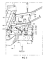
- FIG. 3 is a perspective view of a portion of the apparatus shown in FIG. 1 .
- FIG. 4 is a perspective view of a portion of the apparatus shown in FIG. 1 .
- FIG. 5 is a rear perspective view of the apparatus shown in FIG. 1 .
- FIG. 6A is a perspective view of the apparatus shown in FIG. 1 .
- FIG. 6B is a front perspective view of a portion of the apparatus shown in FIG. 6A .
- FIG. 6C is a perspective view of a portion of the apparatus as shown in FIG. 6A .
- FIGS. 7A-7B are perspective views of a portion of the apparatus shown in FIG. 1 .
- FIG. 8 is a rear perspective view of the apparatus shown in FIG. 1 .
- first and second features are formed in direct contact
- additional features may be formed interposing the first and second features, such that the first and second features may not be in direct contact.
- the apparatus 10 comprises a support structure 100 .
- the support structure 100 may comprise a goose-neck trailer that is configured to be easily transported to and from a worksite.
- the support structure 100 further comprises an elongate trough 102 that extends longitudinally along the length of the support structure 100 .
- the trough 102 is upwardly opening and configured to accommodate a tubular member therein.
- the elongate trough 102 is moveably coupled to a carriage 104
- the carriage 104 is moveably coupled to a carrier 105 .
- the combination carriage 104 and carrier 105 is configured to support the elongate trough 102 during operation and transport.
- the elongate trough 102 may comprise a pipe stop member 106 configured to prevent a tubular member seated in the elongate trough 102 from sliding axially backwards during operation.
- the support structure 100 may additionally comprise a plurality of leveling legs 108 independently operable to adjust the height and angle of the support structure 100 relative to the underlying terrain.
- the leveling legs 108 may also function to align the support structure 100 with an adjacent pipe storage rack (see FIG. 8 ).
- the leveling legs 108 may comprise at least four hydraulically-operable linear actuators, pneumatic actuators, and/or geared electric motor actuators.
- the leveling legs 108 may comprise manual cranks configured to allow a user to manually raise, lower, and tilt the entire apparatus 10 relative to the underlying terrain.
- the apparatus 10 may also comprise a plurality of indexers 202 and pick up arms 204 that are configured to operate in unison to urge tubular members towards and away from the elongate trough 102 .
- the pick up arms 204 may comprise pipe stop ends 206 operable to prevent a tubular member from rolling off of the pick up arm 204 when positioned in a downward direction.
- the pick up arms 204 may be configured to lift tubular members off of an adjacent pipe rack of varying heights.
- FIGS. 3 and 4 illustrated is an exemplary manner in which the indexers 202 and pick up arms 204 operate in unison to urge tubular members towards and/or away from the elongate trough 102 .
- FIG. 3 depicts the pick up arms 204 in an elevated position.
- each pick up arm 204 is attached to a toggle mount 302 .
- a pin 304 is removably coupled to the toggle mount 302 and in exemplary operation may be configured to permit sliding or rolling engagement between the indexers 202 and pick up arms 204 as the pick up arms 204 change elevation.
- the pick up arms 204 and indexers 202 may work simultaneously to urge tubulars toward a desired direction.
- the toggle mount 302 may also comprise a tubular shaft 306 extending perpendicularly downward and configured to be inserted into a toggle member 308 that may be configured to accept and seat the particular shape of the tubular shaft 306 .
- the tubular shaft 306 may comprise, but is not limited to, a section of square tubing that is either mechanically coupled or welded to the toggle mount 302 .
- the tubular shaft 306 may also comprise varying tubular shapes, i.e., cylindrical or hexagonal tubulars.
- a pin 310 may be inserted to prevent axial disengagement between the tubular shaft 306 and the toggle member 308 during operation or transport. For example, by removing the pin 310 , the combination lift arm 204 and toggle mount 302 may be detached completely from the apparatus 10 , and then rotated and reinserted at an angle substantially parallel to the support structure 100 for transportation purposes.
- the toggle member 308 may be rotatably mounted to a shroud 312 and configured to rotate about a pivot point 314 .
- the shroud 312 may be attached to the support structure 100 to seat the indexers 202 when not engaged and further house one or more actuators 316 .
- the actuators 316 may be configured to move the indexers 202 and pick up arms 204 , thus allowing them to work in unison to urge tubular members towards and away from the elongate trough 102 .
- the actuators 316 may be hydraulically-operable linear actuators.
- the actuators 316 may be powered by pneumatics or a geared electric motor.
- an actuator 316 a rotatably coupled to the shroud 312 at one end 402 and to a toggle member 308 at the other end 404 .
- the pick up arm 204 is able to raise ( FIG. 3 ) or lower ( FIG. 4 ).
- a second actuator 316 b is rotatably coupled to the shroud 312 at one end 406 and to an indexer 202 at its other end 408 .
- the indexer 202 may be operable to raise ( FIG. 4 ) or seat itself on the shroud 312 ( FIG. 3 ).
- raised indexers 202 may also act as a pipe stop that prevents further rotational motion of a tubular introduced to the elongate trough 102 from the opposite side of the apparatus 10 .
- the elongate trough 102 lies substantially flush with the adjacent indexers 202 .
- one or more of a series of actuators 502 are mounted to the carriage 104 and rotatably coupled at or near the longitudinal edges of the elongate trough 102 at spaced-apart locations.
- triggering the two actuators 502 a on one side of the elongate trough 102 has the effect of tilting the whole trough 102 in direction 504 relative to the carriage 104 , thereby discharging a tubular member onto the adjacent indexers 202 .
- actuators 502 b located on the opposite side of the trough 102 may be activated, thus discharging a tubular member in direction 506 . This process is further illustrated in FIG. 8 , below.
- the actuators 502 may be hydraulically-operable linear actuators and/or may be powered by pneumatics or electric-geared motors.
- a single actuator 502 may be moveably coupled to the elongate trough 102 and operable to perform the same function as multiple actuators 502 .
- the apparatus 10 with the carrier 105 , carriage 104 and elongate trough 102 combination in an inclined position relative to the support structure 100 .
- the apparatus 10 further comprises a lift arm 602 coupled to the support structure 100 and configured to raise the carrier 105 , carriage 104 and trough 102 combination to an elevated rig floor position.
- the lift arm 602 is rotatably coupled to the carrier 105 at pivot point 606 and may further comprise a hydraulic cylinder 604 configured to control the lift arm 602 in its up and down movement.
- the carrier end 608 While the carrier 105 is being raised or lowered, the carrier end 608 is in constant engagement with a support member 610 mounted to the support structure 100 .
- the support member 610 may comprise a pair of longitudinally extending brackets that extend perpendicularly from the end of the support structure 100 a short distance.
- the carrier end 608 may comprise rollers and/or other rolling means 612 configured to be in rolling engagement with the support member 610 .
- the rolling means 612 secures the carrier end 608 in rolling engagement with the support member 610 .
- the combination carrier 105 , carriage 104 and elongate trough 102 may be moved in direction 614 ( FIG. 6A ) to an elevated position adjacent to a rig floor.
- the rolling means 612 may comprise any configuration capable of moveable engagement with the support member, i.e., a ball bearing configuration or a sliding engagement.
- the carrier 105 comprises one or more crown rollers 616 configured to allow longitudinal rolling engagement between the carriage 104 and carrier 105 .
- a hydraulic cylinder 618 (not visible in FIG. 6C ) is mounted at one end to the carriage 104 while its other end is mounted to the carrier 105 .
- the carriage 104 is drawn longitudinally along carrier 105 towards a rig floor.
- the operator may use this function to position tubulars over the rig floor or to situate them closer to the hole center.
- this function may move the carriage 104 closer to a rig floor worker, thus eliminating the danger in having to lean out over the end of the rig floor in order to place the tubular down on the carriage 104 .
- FIGS. 7A and 7B illustrated is an example of the function and working components of the lift arm 602 .
- FIG. 7A depicts the carriage 104 in its resting position
- FIG. 7B shows the carriage 104 in an elevated position relative to the support structure 100 .
- the lift arm 602 further comprises a linkage 702 pivotally coupled to a rod 708 of the hydraulic cylinder 604 at one point 704 and pivotally coupled to the lift arm 602 at another point 706 .
- the hydraulic cylinder 604 may be triggered to retract its rod 708 , thus rendering a force reaction to the linkage 702 and the lift arm 602 .
- the linkage 702 will simultaneously force the lift arm 602 to an elevated height, while translating the elongate trough 102 in a longitudinal direction towards a position proximate a rig floor.
- the lifting apparatus operates under the principles of kinetics and kinematics using the mechanical advantage of a slider/crank mechanism combined with the mechanical advantage of a four-bar link mechanism.
- the powered slider/crank mechanism may comprise points A-B-C-D, wherein the hydraulic cylinder 604 (link A-B, which includes rod 708 ) may constitute the powered slider (A-B) and a rocker bar B-C-D forms the crank mechanism.
- Rocker bar B-C-D (linkage 702 ) of FIGS. 7A and 7B pivots around fixed point C on the support structure 100 .
- Rocker bar B-C-D pivots as the elongate trough 102 moves between elevated and lowered positions as shown in FIGS.
- FIGS. 7A and 7B show portion C-D of rocker arm B-C-D forms an angle with portion B-C, specifically, when portion B-C is at a vertical orientation and relatively perpendicular to rod 708 , portion C-D is angled generally towards the lift arm and at a diagonal angle with the vertical.
- rocker arm B-C-D causes portion C-D to become generally aligned (i.e., approaches a parallel position) with the link 707 (which connects points D-E) as rocker arm B-C-D is further rotated in a clock-wise manner when rod 708 extends, as seen in FIG. 7A .
- portion C-D has a shorter length than the distance from point E to the pivot point A of lift arm 602 where the hydraulic cylinder 604 attaches to the lift arm 602 .
- the lift arm 602 is lowered from its elevated position as shown in FIG. 7B , by the extension of the rod 708 from the hydraulic cylinder 604 .
- rod 708 extends from its retracted position shown in FIG. 7B
- rocker bar B-C-D is rotated clock-wise about fixed point C, and the link 707 thereby pushes on the lift arm 602 through its pivot point 706 , causing the lift arm 602 to rotate clock-wise about its pivot point, thus lowering the carriage 104 .
- portion C-D of rocker arm B-C-D becomes aligned with (i.e., moves toward being parallel to) the link 707 .
- a tubular 802 may be discharged from the elongate trough 102 in direction 800 by tilting the trough 102 using the actuators 502 .
- the tubular then may roll over the indexers 202 and urged onto the pick up arms 204 , finally being stopped at the pipe stop ends 206 .
- the tubular 802 may then be aligned with and placed on an adjacent pipe storage rack 804 for storage.
- This process may also be reversed in an alternative embodiment of operation, as disclosed herein.
- user may pick up a tubular 802 from an adjacent storage rack 804 by activating the pick up arms 204 , as described in FIGS. 3-4 .
- the pick up arms 204 may be raised to urge the tubular 802 onto the indexers 202 and into the elongate trough 102 .
- the apparatus 10 may be powered by any number of means of alternative power sources.
- the apparatus 10 may be powered by a diesel engine, or any engine of substantially equivalent power output.
- the apparatus 10 is manually operated using manual hydraulic controls.
- the apparatus 10 may also or alternatively be controlled via an optional wireless remote.
- the apparatus may comprise a support structure configured to be positioned adjacent a pipe rack. It may also comprise a carrier moveably coupled to the support structure, and a carriage moveably coupled to the carrier. A trough may extend longitudinally over the support structure and be moveably coupled to the carriage, wherein the trough is configured to receive a tubular member. The trough may be operable to tilt relative to the support structure thereby discharging a tubular.
- the apparatus may further comprise a lift arm that is be coupled between the support structure and the carrier and operable to move the carrier and carriage relative to the support structure, thereby also moving the tubular member received in the trough
- the apparatus may also comprise a plurality of indexers each coupled to the support structure and operable to urge the tubular member toward the trough, and a plurality of pick up arms each slidingly engaged with a corresponding one of the plurality of indexers and operable to retrieve the tubular member from the pipe rack by tilting relative to the support structure.
- the support structure may further comprise a plurality of leveling legs that are collectively operable to raise, lower and tilt the support structure relative to the underlying terrain.
- An apparatus has also been described that comprises a support structure having a carriage and a trough movably coupled to a carrier, wherein a lift arm may be coupled between the support structure and the carrier.
- the lift arm may be laterally offset from being vertically aligned with the carrier.
- the apparatus further comprises an actuator having a first end coupled to the support structure and a linkage coupled between the lift arm and a second end of the actuator, wherein the linkage is operable to transfer operational force of the actuator to the lift arm to raise and lower the carrier, carriage and trough relative to the support structure. Therefore, the lift arm, the actuator, and the linkage may be configured to cooperatively raise the trough from a retracted trough position in which the trough is substantially horizontal and parallel to the support structure.
- a method for moving a tubular member relative to a drilling rig floor comprising picking up a tubular member from a pipe rack adjacent to a support structure by operating a plurality of actuators, each coupled to a corresponding one of a plurality of pick up arms.
- the method further comprises operating the actuators to urge the tubular member onto a plurality of indexers and into a trough extending longitudinally above the support structure, and then operating a lift arm to move the trough and the tubular member therein to an elevated position over the support structure.
- a method for moving a tubular member from a drilling rig floor relative to the ground comprising placing the tubular member lengthwise in a trough that extends angularly from a support structure towards the rig floor and operating a lift arm to lower the trough and the tubular member therein towards the support structure.
- the method further comprises operating a plurality of actuators to tilt the trough to one side thereby discharging the tubular member towards a plurality of indexers.
Abstract
Description
Claims (21)
Priority Applications (6)
| Application Number | Priority Date | Filing Date | Title |
|---|---|---|---|
| US12/098,151 US8016536B2 (en) | 2008-04-04 | 2008-04-04 | Pipe-handling apparatus and methods |
| CA2820152A CA2820152C (en) | 2008-04-04 | 2009-03-26 | Pipe handling apparatus and methods |
| CA2719701A CA2719701C (en) | 2008-04-04 | 2009-03-26 | Pipe handling apparatus and methods |
| CN200980111372.9A CN102016223B (en) | 2008-04-04 | 2009-03-26 | Pipe handling apparatus and methods |
| MX2010010856A MX2010010856A (en) | 2008-04-04 | 2009-03-26 | Pipe handling apparatus and methods. |
| PCT/CA2009/000398 WO2009121172A1 (en) | 2008-04-04 | 2009-03-26 | Pipe handling apparatus and methods |
Applications Claiming Priority (1)
| Application Number | Priority Date | Filing Date | Title |
|---|---|---|---|
| US12/098,151 US8016536B2 (en) | 2008-04-04 | 2008-04-04 | Pipe-handling apparatus and methods |
Publications (2)
| Publication Number | Publication Date |
|---|---|
| US20090252576A1 US20090252576A1 (en) | 2009-10-08 |
| US8016536B2 true US8016536B2 (en) | 2011-09-13 |
Family
ID=41133433
Family Applications (1)
| Application Number | Title | Priority Date | Filing Date |
|---|---|---|---|
| US12/098,151 Active 2028-08-28 US8016536B2 (en) | 2008-04-04 | 2008-04-04 | Pipe-handling apparatus and methods |
Country Status (5)
| Country | Link |
|---|---|
| US (1) | US8016536B2 (en) |
| CN (1) | CN102016223B (en) |
| CA (2) | CA2820152C (en) |
| MX (1) | MX2010010856A (en) |
| WO (1) | WO2009121172A1 (en) |
Cited By (10)
| Publication number | Priority date | Publication date | Assignee | Title |
|---|---|---|---|---|
| US20130336747A1 (en) * | 2012-06-14 | 2013-12-19 | Thomas Dale Hilton | Pipe handling apparatus and method |
| WO2014160056A1 (en) * | 2013-03-13 | 2014-10-02 | Forum Us, Inc. | System for attaching a gullwing to a catwalk |
| US8950996B2 (en) | 2012-06-14 | 2015-02-10 | Warrior Energy Services Corporation | Pipe handling apparatus and method |
| US8998551B2 (en) * | 2011-10-06 | 2015-04-07 | Smith International, Inc. | Tubular positioning system |
| US9267342B2 (en) | 2012-06-14 | 2016-02-23 | Warrior Energy Services Corporation | Pipe handling apparatus and method |
| US9528330B2 (en) | 2013-11-19 | 2016-12-27 | Tesco Corporation | System and method for transporting tubular onto a drilling rig |
| US9573795B1 (en) | 2014-08-27 | 2017-02-21 | Isidro Martinez | Drill pipe screen transporter device |
| US10060201B2 (en) * | 2013-08-02 | 2018-08-28 | Epiroc Rock Drills Aktiebolag | Device for handling drill string components and rock drill rig |
| US10508507B2 (en) | 2017-11-15 | 2019-12-17 | Forum Us, Inc. | Tubular transfer system with variable presentation height and presentation angle |
| US10689924B1 (en) * | 2019-01-31 | 2020-06-23 | CW10K40 LLC, Paracorp Incorporated | Lift assist for a truss |
Families Citing this family (21)
| Publication number | Priority date | Publication date | Assignee | Title |
|---|---|---|---|---|
| US7832974B2 (en) * | 2005-06-01 | 2010-11-16 | Canrig Drilling Technology Ltd. | Pipe-handling apparatus |
| US8033779B2 (en) * | 2008-01-31 | 2011-10-11 | Canrig Drilling Technology Ltd. | Pipe handling apparatus and methods |
| US8961093B2 (en) | 2010-07-23 | 2015-02-24 | National Oilwell Varco, L.P. | Drilling rig pipe transfer systems and methods |
| US9243461B1 (en) * | 2012-01-17 | 2016-01-26 | Loadmaster Universal Rigs, Inc. | Catwalk mechanism and method for installing tubulars on a drill string |
| US9080397B2 (en) * | 2012-03-21 | 2015-07-14 | Darcy LUDWIG | Pipe handling apparatus |
| US9057227B2 (en) * | 2012-04-10 | 2015-06-16 | Key Energy Services, Llc | Pipe handling apparatus |
| SE536564C2 (en) * | 2012-06-28 | 2014-02-25 | Atlas Copco Rocktech Ab | Device and method for handling drill string components and rock drilling rigs |
| CN103541668B (en) * | 2012-07-17 | 2016-01-20 | 中国石油化工股份有限公司 | The rod tube lifting of mechanization workover treatment well site opens and closes method and the device of elevator |
| US20140030045A1 (en) * | 2012-07-24 | 2014-01-30 | Alan Beck | Pipe pick-up and lay down apparatus |
| CN103696710B (en) * | 2012-09-28 | 2016-04-20 | 中国石油化工股份有限公司 | Aboveground working string conveying device |
| US9562406B2 (en) | 2012-11-19 | 2017-02-07 | Key Energy Services, Llc | Mechanized and automated well service rig |
| US9580979B2 (en) * | 2013-03-01 | 2017-02-28 | Itrec B.V. | Tubulars handling system and apparatus |
| CN104278956B (en) * | 2013-07-12 | 2017-07-14 | 中国石油天然气股份有限公司 | Oil pipe hydraulic pressure lifting device and application method |
| US9725970B1 (en) * | 2013-09-18 | 2017-08-08 | CRW Contracting, Inc. | Compact pipe handling trailer |
| CN103510887B (en) * | 2013-10-14 | 2015-11-25 | 江苏如通石油机械股份有限公司 | Power fortune pipe device |
| CA2878747A1 (en) * | 2014-01-22 | 2015-07-22 | Nabors Drilling Canada Limited | Wellbore equipment handling device |
| US9624740B2 (en) * | 2014-06-26 | 2017-04-18 | Tammy Sue Molski | Hydraulic pipe handling apparatus |
| US10221634B2 (en) * | 2015-04-14 | 2019-03-05 | Nabors Drilling Technologies Usa, Inc. | Catwalk system and method |
| CN105756580B (en) * | 2016-04-08 | 2019-03-05 | 山东胜利石油装备产业技术研究院 | A kind of Full automatic oil pipe column comb shifting pipe device |
| CN108561089B (en) * | 2018-06-19 | 2024-04-09 | 四川宏华石油设备有限公司 | Pipe processing device |
| US11434705B2 (en) * | 2020-07-14 | 2022-09-06 | Summit Laydown Services Inc. | Tubular make-up and delivery system |
Citations (72)
| Publication number | Priority date | Publication date | Assignee | Title |
|---|---|---|---|---|
| US982977A (en) * | 1909-04-24 | 1911-01-31 | Ralph L Morgan | Loading and unloading device. |
| US1440155A (en) * | 1921-06-13 | 1922-12-26 | Agnes A Junkin | Dump-body hoist |
| US1536960A (en) * | 1923-03-26 | 1925-05-05 | Grant Waldref | Hoisting mechanism for tilting bodies of dump vehicles |
| US1940043A (en) * | 1931-06-08 | 1933-12-19 | Perfection Steel Body Company | Dumping truck |
| US2615544A (en) | 1950-03-15 | 1952-10-28 | Frank J Rynders | Unloading device |
| US2643006A (en) * | 1949-09-28 | 1953-06-23 | William R King | Automatic pipe handler |
| US2880881A (en) | 1954-01-04 | 1959-04-07 | C N Housh | Unitized pipe rack |
| US3159286A (en) | 1963-10-17 | 1964-12-01 | Sr Richard B Freeman | Drill pipe handling apparatus |
| US3169645A (en) | 1961-08-11 | 1965-02-16 | Sr Richard B Freeman | Drill pipe and collar laying down machine |
| US3217900A (en) * | 1964-04-06 | 1965-11-16 | Herman W Kupetzky | Mechanism for missile transfer |
| US3307719A (en) | 1965-04-23 | 1967-03-07 | Tag A Long Trailers Inc | Floating ramp |
| US3494483A (en) | 1968-10-04 | 1970-02-10 | James E Smart | Portable pipe handling apparatus |
| US3651959A (en) | 1969-05-14 | 1972-03-28 | Inst Francais Du Petrole | New device for handling elongated members |
| US3706347A (en) | 1971-03-18 | 1972-12-19 | Cicero C Brown | Pipe handling system for use in well drilling |
| US3780883A (en) | 1971-03-18 | 1973-12-25 | Brown Oil Tools | Pipe handling system for use in well drilling |
| US3785506A (en) | 1971-09-10 | 1974-01-15 | Roger A Crocker | Drill pipe handling apparatus |
| US3810553A (en) | 1972-08-31 | 1974-05-14 | R Crocker | Pipe handling device |
| US3883820A (en) | 1973-04-27 | 1975-05-13 | Coherent Radiation | Gas laser having improved multiple-part resonator adjustment |
| US3883009A (en) | 1973-07-09 | 1975-05-13 | Jr John J Swoboda | Racking arm for pipe sections, drill collars, riser pipe, and the like used in well drilling operations |
| US3894515A (en) | 1973-12-14 | 1975-07-15 | Isom Franklin Plyler | Animal loading and unloading apparatus |
| US4051956A (en) * | 1976-07-26 | 1977-10-04 | Teague J T | Horizontal pipe handling apparatus |
| US4051775A (en) | 1975-10-23 | 1977-10-04 | Watson Edward F | Apparatus for automatically positioning with respect to a predetermined operation station |
| US4067453A (en) | 1976-04-19 | 1978-01-10 | Western Gear Corporation | Pipe delivery system |
| US4129221A (en) | 1976-04-30 | 1978-12-12 | Western Gear Corporation | Pipe handling apparatus |
| US4143534A (en) | 1974-10-16 | 1979-03-13 | Th. Kieserling & Albrecht | Workpiece feed channel |
| US4147266A (en) * | 1976-03-19 | 1979-04-03 | Bennes Marrel | Semi-trailer for handling and transporting standardized containers |
| US4235566A (en) | 1978-12-04 | 1980-11-25 | Beeman Archie W | Pipe-conveying catwalk |
| US4347028A (en) | 1979-09-17 | 1982-08-31 | Automatic Pipe Racker, Inc. | Pipe handling apparatus |
| US4361223A (en) | 1980-12-01 | 1982-11-30 | American Can Company | Material handling apparatus |
| CA1139299A (en) | 1980-10-01 | 1983-01-11 | Archie W. Beeman | Pipe-conveying catwalk |
| US4379676A (en) | 1980-02-27 | 1983-04-12 | Ingram Corporation | Pipe handling system |
| US4380297A (en) | 1980-02-27 | 1983-04-19 | Ingram Corporation | Pipe storage system |
| US4382738A (en) | 1980-02-27 | 1983-05-10 | Ingram Corporation | Pipe handling system |
| US4386883A (en) | 1980-09-30 | 1983-06-07 | Rig-A-Matic, Inc. | Materials lifting apparatus |
| US4403898A (en) | 1981-12-31 | 1983-09-13 | Thompson Carroll R | Pipe pick-up and laydown machine |
| US4426182A (en) | 1980-09-10 | 1984-01-17 | Ingram Corporation | Tubular handling apparatus |
| CA1161427A (en) | 1981-09-10 | 1984-01-31 | Robert Frias | Tubular handling apparatus |
| US4470740A (en) | 1980-09-10 | 1984-09-11 | Ingram Corporation | Apron for pipe handling system |
| US4474520A (en) | 1982-03-02 | 1984-10-02 | Ingram Corporation | Pipe handling machine |
| US4494899A (en) | 1982-04-28 | 1985-01-22 | Tri-Star Enterprises, Inc. | Pipe trough for transporting pipe between upper and lower positions |
| CA1185228A (en) | 1981-06-01 | 1985-04-09 | George I. Boyadjieff | Well pipe jack |
| US4533055A (en) * | 1982-06-02 | 1985-08-06 | Walker-Neer Manufacturing Co., Inc. | Storage rack for drilling tubulars |
| CA1195241A (en) | 1981-12-21 | 1985-10-15 | Varco International, Inc. | Positioning of well pipe jack in a rig |
| US4696207A (en) | 1985-04-26 | 1987-09-29 | Varco International, Inc. | Well pipe handling machine |
| US4709766A (en) | 1985-04-26 | 1987-12-01 | Varco International, Inc. | Well pipe handling machine |
| US4765401A (en) | 1986-08-21 | 1988-08-23 | Varco International, Inc. | Apparatus for handling well pipe |
| US4960356A (en) | 1989-11-29 | 1990-10-02 | Personal Watercraft Creations, Inc. | Jet propelled watercraft loading and storing apparatus |
| US5077852A (en) | 1989-04-03 | 1992-01-07 | Kvistberga Produkter Hb | Loading ramps |
| US5137114A (en) | 1991-10-28 | 1992-08-11 | The Moving Company | Stair track device |
| CA2115810A1 (en) | 1993-10-04 | 1995-04-05 | George I. Boyadjieff | Pipe Transfer System |
| US5542810A (en) | 1994-05-31 | 1996-08-06 | Florus; H. Cameron | Easily removable dual purpose apparatus for safely transporting personal watercraft in truck bed |
| CA2224638A1 (en) | 1997-12-12 | 1999-06-12 | Custom Pipe Handlers Inc. | Improved pipe handling apparatus |
| US6079925A (en) | 1998-06-19 | 2000-06-27 | Morgan; Carl | Method and apparatus for lifting oilfield goods to a derrick floor |
| US6533519B1 (en) | 2000-07-20 | 2003-03-18 | Hydra-Walk, Inc. | Pipe handling apparatus |
| US20030155154A1 (en) | 2002-02-21 | 2003-08-21 | Oser Michael S. | System and method for transferring pipe |
| CA2496440A1 (en) | 2002-05-03 | 2003-11-13 | Technologies Alliance, Inc., D/B/A Oilpatch Technologies | Height-adjustable pipe pick-up and laydown machine |
| US20040136813A1 (en) | 1998-02-14 | 2004-07-15 | Weatherford/Lamb, Inc. | Apparatus for delivering a tubular to a wellbore |
| US20040208730A1 (en) | 2003-04-18 | 2004-10-21 | Morelli Vince E. | Pipe handling apparatus for presenting sections of pipe to a derrick work floor having a high-speed carriage assembly |
| US20050079044A1 (en) | 2003-10-10 | 2005-04-14 | Handley Richard A. | Multi-position height adjustment system for a pipe handling apparatus |
| UA74759C2 (en) | 2005-08-30 | 2006-01-16 | Borys Mykhailovych Presniakov | Drill unit for drilling wells for piles or other similar building structures |
| US20060045655A1 (en) | 2004-06-25 | 2006-03-02 | Kerry Wells | Oilfield pipe-handling apparatus |
| US20060124356A1 (en) | 2004-12-13 | 2006-06-15 | Gust Cheryl J | Apparatus and method for handling wellbore tubulars |
| CA2508998A1 (en) | 2005-06-01 | 2006-12-01 | Pragma Engineering Ltd | Pipe-handling apparatus |
| WO2006128300A1 (en) | 2005-06-01 | 2006-12-07 | Canrig Drilling Technology Ltd. | Pipe-handling apparatus |
| CA2551884A1 (en) | 2005-07-19 | 2007-01-19 | National-Oilwell, L.P. | Single joint drilling system with inclined pipe handling system |
| US20070114113A1 (en) | 2005-11-18 | 2007-05-24 | Pop's Laydown Service, L.L.C. | Methods and Systems of Handling Pipe |
| US20070177967A1 (en) | 2006-02-01 | 2007-08-02 | Gerald Lesko | Pipe indexer/kicker |
| US20070193749A1 (en) | 2006-02-22 | 2007-08-23 | Live Well Service, A Division Of Precision Drilling Corporation | Mobile snubbing system |
| US20070221385A1 (en) | 2006-03-21 | 2007-09-27 | Saxon Energy Services Inc. | Apparatus and Method for Forming Stands |
| US7300239B2 (en) * | 2001-05-14 | 2007-11-27 | Wilhelm Alfred Benedikt | Hoist for loading and unloading objects on a truck bed |
| US20070286708A1 (en) | 2006-06-09 | 2007-12-13 | Columbia Trailer Co., Inc. | Method and apparatus for handling pipe |
| US20090196711A1 (en) | 2008-01-31 | 2009-08-06 | Nabors Global Holdings Ltd. | Pipe Handling Apparatus and Methods |
Family Cites Families (5)
| Publication number | Priority date | Publication date | Assignee | Title |
|---|---|---|---|---|
| US6535519B1 (en) * | 1998-08-28 | 2003-03-18 | Lsi Logic Corporation | Method and apparatus for data sharing between two different blocks in an integrated circuit |
| CA2510137C (en) * | 2004-06-25 | 2011-05-17 | Kerry Wells | Oilfield pipe-handling apparatus |
| US7744327B2 (en) * | 2004-10-07 | 2010-06-29 | Itrec B.V. | Tubular handling apparatus and a drilling rig |
| CA2517630A1 (en) * | 2004-12-13 | 2006-06-13 | Cheryl J. Gust | Apparatus and method for handling wellbore tubulars |
| CN201013271Y (en) * | 2007-03-26 | 2008-01-30 | 南阳二机石油装备(集团)有限公司 | Fully-hydraulic drilling rod bleeder |
-
2008
- 2008-04-04 US US12/098,151 patent/US8016536B2/en active Active
-
2009
- 2009-03-26 CA CA2820152A patent/CA2820152C/en not_active Expired - Fee Related
- 2009-03-26 WO PCT/CA2009/000398 patent/WO2009121172A1/en active Application Filing
- 2009-03-26 CN CN200980111372.9A patent/CN102016223B/en not_active Expired - Fee Related
- 2009-03-26 MX MX2010010856A patent/MX2010010856A/en active IP Right Grant
- 2009-03-26 CA CA2719701A patent/CA2719701C/en not_active Expired - Fee Related
Patent Citations (80)
| Publication number | Priority date | Publication date | Assignee | Title |
|---|---|---|---|---|
| US982977A (en) * | 1909-04-24 | 1911-01-31 | Ralph L Morgan | Loading and unloading device. |
| US1440155A (en) * | 1921-06-13 | 1922-12-26 | Agnes A Junkin | Dump-body hoist |
| US1536960A (en) * | 1923-03-26 | 1925-05-05 | Grant Waldref | Hoisting mechanism for tilting bodies of dump vehicles |
| US1940043A (en) * | 1931-06-08 | 1933-12-19 | Perfection Steel Body Company | Dumping truck |
| US2643006A (en) * | 1949-09-28 | 1953-06-23 | William R King | Automatic pipe handler |
| US2615544A (en) | 1950-03-15 | 1952-10-28 | Frank J Rynders | Unloading device |
| US2880881A (en) | 1954-01-04 | 1959-04-07 | C N Housh | Unitized pipe rack |
| US3169645A (en) | 1961-08-11 | 1965-02-16 | Sr Richard B Freeman | Drill pipe and collar laying down machine |
| US3159286A (en) | 1963-10-17 | 1964-12-01 | Sr Richard B Freeman | Drill pipe handling apparatus |
| US3217900A (en) * | 1964-04-06 | 1965-11-16 | Herman W Kupetzky | Mechanism for missile transfer |
| US3307719A (en) | 1965-04-23 | 1967-03-07 | Tag A Long Trailers Inc | Floating ramp |
| US3494483A (en) | 1968-10-04 | 1970-02-10 | James E Smart | Portable pipe handling apparatus |
| US3651959A (en) | 1969-05-14 | 1972-03-28 | Inst Francais Du Petrole | New device for handling elongated members |
| US3706347A (en) | 1971-03-18 | 1972-12-19 | Cicero C Brown | Pipe handling system for use in well drilling |
| US3780883A (en) | 1971-03-18 | 1973-12-25 | Brown Oil Tools | Pipe handling system for use in well drilling |
| US3785506A (en) | 1971-09-10 | 1974-01-15 | Roger A Crocker | Drill pipe handling apparatus |
| US3810553A (en) | 1972-08-31 | 1974-05-14 | R Crocker | Pipe handling device |
| US3883820A (en) | 1973-04-27 | 1975-05-13 | Coherent Radiation | Gas laser having improved multiple-part resonator adjustment |
| US3883009A (en) | 1973-07-09 | 1975-05-13 | Jr John J Swoboda | Racking arm for pipe sections, drill collars, riser pipe, and the like used in well drilling operations |
| US3894515A (en) | 1973-12-14 | 1975-07-15 | Isom Franklin Plyler | Animal loading and unloading apparatus |
| US4143534A (en) | 1974-10-16 | 1979-03-13 | Th. Kieserling & Albrecht | Workpiece feed channel |
| US4051775A (en) | 1975-10-23 | 1977-10-04 | Watson Edward F | Apparatus for automatically positioning with respect to a predetermined operation station |
| US4147266A (en) * | 1976-03-19 | 1979-04-03 | Bennes Marrel | Semi-trailer for handling and transporting standardized containers |
| US4067453A (en) | 1976-04-19 | 1978-01-10 | Western Gear Corporation | Pipe delivery system |
| US4129221A (en) | 1976-04-30 | 1978-12-12 | Western Gear Corporation | Pipe handling apparatus |
| US4051956A (en) * | 1976-07-26 | 1977-10-04 | Teague J T | Horizontal pipe handling apparatus |
| US4235566A (en) | 1978-12-04 | 1980-11-25 | Beeman Archie W | Pipe-conveying catwalk |
| US4347028A (en) | 1979-09-17 | 1982-08-31 | Automatic Pipe Racker, Inc. | Pipe handling apparatus |
| US4380297A (en) | 1980-02-27 | 1983-04-19 | Ingram Corporation | Pipe storage system |
| US4382738A (en) | 1980-02-27 | 1983-05-10 | Ingram Corporation | Pipe handling system |
| US4379676A (en) | 1980-02-27 | 1983-04-12 | Ingram Corporation | Pipe handling system |
| US4426182A (en) | 1980-09-10 | 1984-01-17 | Ingram Corporation | Tubular handling apparatus |
| US4470740A (en) | 1980-09-10 | 1984-09-11 | Ingram Corporation | Apron for pipe handling system |
| US4386883A (en) | 1980-09-30 | 1983-06-07 | Rig-A-Matic, Inc. | Materials lifting apparatus |
| CA1139299A (en) | 1980-10-01 | 1983-01-11 | Archie W. Beeman | Pipe-conveying catwalk |
| US4361223A (en) | 1980-12-01 | 1982-11-30 | American Can Company | Material handling apparatus |
| CA1185228A (en) | 1981-06-01 | 1985-04-09 | George I. Boyadjieff | Well pipe jack |
| CA1161427A (en) | 1981-09-10 | 1984-01-31 | Robert Frias | Tubular handling apparatus |
| CA1195241A (en) | 1981-12-21 | 1985-10-15 | Varco International, Inc. | Positioning of well pipe jack in a rig |
| US4403898A (en) | 1981-12-31 | 1983-09-13 | Thompson Carroll R | Pipe pick-up and laydown machine |
| US4474520A (en) | 1982-03-02 | 1984-10-02 | Ingram Corporation | Pipe handling machine |
| US4494899A (en) | 1982-04-28 | 1985-01-22 | Tri-Star Enterprises, Inc. | Pipe trough for transporting pipe between upper and lower positions |
| US4533055A (en) * | 1982-06-02 | 1985-08-06 | Walker-Neer Manufacturing Co., Inc. | Storage rack for drilling tubulars |
| US4696207A (en) | 1985-04-26 | 1987-09-29 | Varco International, Inc. | Well pipe handling machine |
| US4709766A (en) | 1985-04-26 | 1987-12-01 | Varco International, Inc. | Well pipe handling machine |
| CA1254194A (en) | 1985-04-26 | 1989-05-16 | George I. Boyadjieff | Well pipe handling machine |
| US4765401A (en) | 1986-08-21 | 1988-08-23 | Varco International, Inc. | Apparatus for handling well pipe |
| US5077852A (en) | 1989-04-03 | 1992-01-07 | Kvistberga Produkter Hb | Loading ramps |
| US4960356A (en) | 1989-11-29 | 1990-10-02 | Personal Watercraft Creations, Inc. | Jet propelled watercraft loading and storing apparatus |
| US5137114A (en) | 1991-10-28 | 1992-08-11 | The Moving Company | Stair track device |
| CA2115810A1 (en) | 1993-10-04 | 1995-04-05 | George I. Boyadjieff | Pipe Transfer System |
| US5542810A (en) | 1994-05-31 | 1996-08-06 | Florus; H. Cameron | Easily removable dual purpose apparatus for safely transporting personal watercraft in truck bed |
| CA2224638A1 (en) | 1997-12-12 | 1999-06-12 | Custom Pipe Handlers Inc. | Improved pipe handling apparatus |
| US20040136813A1 (en) | 1998-02-14 | 2004-07-15 | Weatherford/Lamb, Inc. | Apparatus for delivering a tubular to a wellbore |
| US6079925A (en) | 1998-06-19 | 2000-06-27 | Morgan; Carl | Method and apparatus for lifting oilfield goods to a derrick floor |
| US6533519B1 (en) | 2000-07-20 | 2003-03-18 | Hydra-Walk, Inc. | Pipe handling apparatus |
| US20040197166A1 (en) | 2000-07-20 | 2004-10-07 | Tolman E. Kent | Pipe handling apparatus |
| US7300239B2 (en) * | 2001-05-14 | 2007-11-27 | Wilhelm Alfred Benedikt | Hoist for loading and unloading objects on a truck bed |
| US20030155154A1 (en) | 2002-02-21 | 2003-08-21 | Oser Michael S. | System and method for transferring pipe |
| CA2496440A1 (en) | 2002-05-03 | 2003-11-13 | Technologies Alliance, Inc., D/B/A Oilpatch Technologies | Height-adjustable pipe pick-up and laydown machine |
| US20060104746A1 (en) * | 2002-05-03 | 2006-05-18 | Thompson Carroll R | Height-adjustable pipe pick-up and laydown machine |
| US20040208730A1 (en) | 2003-04-18 | 2004-10-21 | Morelli Vince E. | Pipe handling apparatus for presenting sections of pipe to a derrick work floor having a high-speed carriage assembly |
| US20050079044A1 (en) | 2003-10-10 | 2005-04-14 | Handley Richard A. | Multi-position height adjustment system for a pipe handling apparatus |
| US7163367B2 (en) | 2003-10-10 | 2007-01-16 | Forum Canada Ulc | Multi-position height adjustment system for a pipe handling apparatus |
| US20060045655A1 (en) | 2004-06-25 | 2006-03-02 | Kerry Wells | Oilfield pipe-handling apparatus |
| US7473065B2 (en) | 2004-06-25 | 2009-01-06 | Kerry Wells | Oilfield pipe-handling apparatus |
| US20060124356A1 (en) | 2004-12-13 | 2006-06-15 | Gust Cheryl J | Apparatus and method for handling wellbore tubulars |
| CA2508998A1 (en) | 2005-06-01 | 2006-12-01 | Pragma Engineering Ltd | Pipe-handling apparatus |
| WO2006128300A1 (en) | 2005-06-01 | 2006-12-07 | Canrig Drilling Technology Ltd. | Pipe-handling apparatus |
| US20060285941A1 (en) | 2005-06-01 | 2006-12-21 | Pragma Engineering Ltd. | Pipe-handling apparatus |
| EP1888872A1 (en) | 2005-06-01 | 2008-02-20 | Canrig Drilling Technology, Ltd. | Pipe-handling apparatus |
| CA2551884A1 (en) | 2005-07-19 | 2007-01-19 | National-Oilwell, L.P. | Single joint drilling system with inclined pipe handling system |
| UA74759C2 (en) | 2005-08-30 | 2006-01-16 | Borys Mykhailovych Presniakov | Drill unit for drilling wells for piles or other similar building structures |
| US20070114113A1 (en) | 2005-11-18 | 2007-05-24 | Pop's Laydown Service, L.L.C. | Methods and Systems of Handling Pipe |
| US20070177967A1 (en) | 2006-02-01 | 2007-08-02 | Gerald Lesko | Pipe indexer/kicker |
| US7469749B2 (en) | 2006-02-22 | 2008-12-30 | Live Well Service, A Division Of Precision Drilling Corporation | Mobile snubbing system |
| US20070193749A1 (en) | 2006-02-22 | 2007-08-23 | Live Well Service, A Division Of Precision Drilling Corporation | Mobile snubbing system |
| US20070221385A1 (en) | 2006-03-21 | 2007-09-27 | Saxon Energy Services Inc. | Apparatus and Method for Forming Stands |
| US20070286708A1 (en) | 2006-06-09 | 2007-12-13 | Columbia Trailer Co., Inc. | Method and apparatus for handling pipe |
| US20090196711A1 (en) | 2008-01-31 | 2009-08-06 | Nabors Global Holdings Ltd. | Pipe Handling Apparatus and Methods |
Non-Patent Citations (7)
| Title |
|---|
| http://www.columbiacorp.com/#/our-company/video-gallery/, Web site Screen Shot, 1 page. |
| http://www.columbiacorp.com/#/products/pipe-handlers/4-arm-pipe-handler/, Web site Screen Shot, 1 page. |
| International Search Report WO06/128300 (PCT/CA06/000904). |
| Operating Manual for the Pipe Handler-machine set-up, 41 pages. |
| Operating Manual for the Pipe Handler—machine set-up, 41 pages. |
| PCT International Preliminary Report on Patentability WO06/128300 (PCT/CA06/000904). |
| PCT Written Opinion of the International Searching Authority WO06/128300 (PCT/CA06/000904). |
Cited By (12)
| Publication number | Priority date | Publication date | Assignee | Title |
|---|---|---|---|---|
| US8998551B2 (en) * | 2011-10-06 | 2015-04-07 | Smith International, Inc. | Tubular positioning system |
| US20130336747A1 (en) * | 2012-06-14 | 2013-12-19 | Thomas Dale Hilton | Pipe handling apparatus and method |
| US8899901B2 (en) * | 2012-06-14 | 2014-12-02 | Warrior Energy Services Corporation | Pipe handling apparatus and method |
| US8950996B2 (en) | 2012-06-14 | 2015-02-10 | Warrior Energy Services Corporation | Pipe handling apparatus and method |
| US9267342B2 (en) | 2012-06-14 | 2016-02-23 | Warrior Energy Services Corporation | Pipe handling apparatus and method |
| WO2014160056A1 (en) * | 2013-03-13 | 2014-10-02 | Forum Us, Inc. | System for attaching a gullwing to a catwalk |
| US9506302B2 (en) | 2013-03-13 | 2016-11-29 | Forum Us, Inc. | System for attaching a gullwing to a catwalk |
| US10060201B2 (en) * | 2013-08-02 | 2018-08-28 | Epiroc Rock Drills Aktiebolag | Device for handling drill string components and rock drill rig |
| US9528330B2 (en) | 2013-11-19 | 2016-12-27 | Tesco Corporation | System and method for transporting tubular onto a drilling rig |
| US9573795B1 (en) | 2014-08-27 | 2017-02-21 | Isidro Martinez | Drill pipe screen transporter device |
| US10508507B2 (en) | 2017-11-15 | 2019-12-17 | Forum Us, Inc. | Tubular transfer system with variable presentation height and presentation angle |
| US10689924B1 (en) * | 2019-01-31 | 2020-06-23 | CW10K40 LLC, Paracorp Incorporated | Lift assist for a truss |
Also Published As
| Publication number | Publication date |
|---|---|
| CA2820152A1 (en) | 2009-10-08 |
| MX2010010856A (en) | 2011-02-23 |
| CN102016223B (en) | 2014-02-19 |
| US20090252576A1 (en) | 2009-10-08 |
| CN102016223A (en) | 2011-04-13 |
| WO2009121172A1 (en) | 2009-10-08 |
| CA2820152C (en) | 2016-11-01 |
| CA2719701A1 (en) | 2009-10-08 |
| CA2719701C (en) | 2014-01-14 |
Similar Documents
| Publication | Publication Date | Title |
|---|---|---|
| US8016536B2 (en) | Pipe-handling apparatus and methods | |
| US7665944B2 (en) | Pipe pick-up and laydown apparatus and method | |
| US10988994B2 (en) | Pipe handler and pipe loader for a well rig | |
| US6719515B2 (en) | Pipe handling apparatus | |
| US7736119B2 (en) | Horizontal pipe handling system | |
| CA2173995C (en) | Pipe racker assembly | |
| US4684314A (en) | Pipe handling apparatus | |
| CA2617028A1 (en) | A drill pipe handling and moving system | |
| US9080397B2 (en) | Pipe handling apparatus | |
| US7614492B2 (en) | Methods and systems of handling pipe | |
| CA2472387A1 (en) | Oilfield pipe-handling apparatus | |
| US9267342B2 (en) | Pipe handling apparatus and method | |
| US20090127001A1 (en) | Pipehandler | |
| EP2039648A1 (en) | Material handling means | |
| CN201010452Y (en) | Upright post telehoist choosing work direction by rake-plough car |
Legal Events
| Date | Code | Title | Description |
|---|---|---|---|
| AS | Assignment |
Owner name: NABORS GLOBAL HOLDINGS, LTD., BERMUDA Free format text: ASSIGNMENT OF ASSIGNORS INTEREST;ASSIGNORS:GERBER, ANDREW;HUNTER, DOUGLAS A.;REEL/FRAME:020923/0606 Effective date: 20070502 |
|
| AS | Assignment |
Owner name: CANRIG DRILLING TECHNOLOGY LTD., TEXAS Free format text: ASSIGNMENT OF ASSIGNORS INTEREST;ASSIGNOR:NABORS GLOBAL HOLDINGS LIMITED;REEL/FRAME:024823/0218 Effective date: 20100726 |
|
| STCF | Information on status: patent grant |
Free format text: PATENTED CASE |
|
| CC | Certificate of correction | ||
| FPAY | Fee payment |
Year of fee payment: 4 |
|
| AS | Assignment |
Owner name: NABORS DRILLING TECHNOLOGIES USA, INC., TEXAS Free format text: MERGER;ASSIGNOR:CANRIG DRILLING TECHNOLOGY LTD.;REEL/FRAME:043601/0745 Effective date: 20170630 |
|
| MAFP | Maintenance fee payment |
Free format text: PAYMENT OF MAINTENANCE FEE, 8TH YEAR, LARGE ENTITY (ORIGINAL EVENT CODE: M1552); ENTITY STATUS OF PATENT OWNER: LARGE ENTITY Year of fee payment: 8 |
|
| MAFP | Maintenance fee payment |
Free format text: PAYMENT OF MAINTENANCE FEE, 12TH YEAR, LARGE ENTITY (ORIGINAL EVENT CODE: M1553); ENTITY STATUS OF PATENT OWNER: LARGE ENTITY Year of fee payment: 12 |