US8023144B2 - Method for generating transposed image data - Google Patents
Method for generating transposed image data Download PDFInfo
- Publication number
- US8023144B2 US8023144B2 US11/456,651 US45665106A US8023144B2 US 8023144 B2 US8023144 B2 US 8023144B2 US 45665106 A US45665106 A US 45665106A US 8023144 B2 US8023144 B2 US 8023144B2
- Authority
- US
- United States
- Prior art keywords
- data blocks
- format
- image data
- memory
- data
- Prior art date
- Legal status (The legal status is an assumption and is not a legal conclusion. Google has not performed a legal analysis and makes no representation as to the accuracy of the status listed.)
- Active, expires
Links
- 238000000034 method Methods 0.000 title claims abstract description 35
- 238000003384 imaging method Methods 0.000 claims abstract description 34
- 238000007639 printing Methods 0.000 claims description 20
- 230000003139 buffering effect Effects 0.000 claims 2
- 230000007246 mechanism Effects 0.000 description 75
- 239000000976 ink Substances 0.000 description 20
- 238000006243 chemical reaction Methods 0.000 description 14
- 238000004891 communication Methods 0.000 description 13
- 230000008569 process Effects 0.000 description 9
- 239000003086 colorant Substances 0.000 description 7
- 230000006870 function Effects 0.000 description 6
- 238000003491 array Methods 0.000 description 4
- 238000010586 diagram Methods 0.000 description 4
- 238000007641 inkjet printing Methods 0.000 description 4
- 238000005516 engineering process Methods 0.000 description 3
- 238000012545 processing Methods 0.000 description 3
- 230000008878 coupling Effects 0.000 description 2
- 238000010168 coupling process Methods 0.000 description 2
- 238000005859 coupling reaction Methods 0.000 description 2
- 230000000694 effects Effects 0.000 description 2
- 238000009825 accumulation Methods 0.000 description 1
- 238000010276 construction Methods 0.000 description 1
- 238000013500 data storage Methods 0.000 description 1
- 230000001419 dependent effect Effects 0.000 description 1
- 238000011161 development Methods 0.000 description 1
- 239000004744 fabric Substances 0.000 description 1
- 238000012432 intermediate storage Methods 0.000 description 1
- 238000012986 modification Methods 0.000 description 1
- 230000004048 modification Effects 0.000 description 1
- 239000000049 pigment Substances 0.000 description 1
- 230000009467 reduction Effects 0.000 description 1
- 238000011160 research Methods 0.000 description 1
- 230000003068 static effect Effects 0.000 description 1
- 238000003860 storage Methods 0.000 description 1
Images


Classifications
-
- H—ELECTRICITY
- H04—ELECTRIC COMMUNICATION TECHNIQUE
- H04N—PICTORIAL COMMUNICATION, e.g. TELEVISION
- H04N1/00—Scanning, transmission or reproduction of documents or the like, e.g. facsimile transmission; Details thereof
- H04N1/40—Picture signal circuits
-
- G—PHYSICS
- G06—COMPUTING; CALCULATING OR COUNTING
- G06K—GRAPHICAL DATA READING; PRESENTATION OF DATA; RECORD CARRIERS; HANDLING RECORD CARRIERS
- G06K15/00—Arrangements for producing a permanent visual presentation of the output data, e.g. computer output printers
- G06K15/02—Arrangements for producing a permanent visual presentation of the output data, e.g. computer output printers using printers
- G06K15/10—Arrangements for producing a permanent visual presentation of the output data, e.g. computer output printers using printers by matrix printers
Definitions
- the present invention relates generally to imaging, and more particularly to a method for generating image data for use in an imaging apparatus, including performing a combined format and transpose operation.
- ink jet printing systems produce images by printing patterns of dots on a sheet of print media, such as paper.
- Such systems typically include two main mechanisms for determining the location of dots on the page, namely, a halftone mechanism and a formatting mechanism.
- Such mechanisms may be implemented, for example, in software, firmware, hardware, or a combination thereof, and may reference one or more lookup tables.
- the halftone mechanism compensates for the inability of an ink jet printer, i.e., a binary printer, to print a continuous range of tones.
- a binary printer can only produce colors by either printing or not printing a dot of ink.
- halftoning involves the eventual pattern of dots placed on a page as a result of the printing process and the halftone pattern is visible to the user after the page is completely rendered.
- the formatter mechanism generates color raster data, e.g., cyan, magenta, yellow, and black (CMYK) raster data.
- color raster data e.g., cyan, magenta, yellow, and black (CMYK) raster data.
- CMYK cyan, magenta, yellow, and black
- a transpose operation which is separate and independent from the format operation, then reads the stored formatted image data from the printer main memory, performs the transpose function, and sends the transposed image data to the printhead logic.
- format refers to an operation in which halftone image data is converted for printing on a particular pass of a particular printhead over the sheet of print media.
- transpose refers to an operation where the formatted image data is rearranged to meet the requirements of the printhead logic of the printhead used in performing the printing operation.
- the transpose operation may be a direct memory access (DMA) bandwidth intense operation and usually becomes a cost versus performance tradeoff.
- DMA direct memory access
- Acceptable DMA bandwidth requirements are met in this configuration at a relatively low cost in logic area.
- a 64 ⁇ 64 array might be used to allow for two words in and two words out from/to memory. This would allow for a 50 percent increase in DMA performance but a greater than 400 percent increase in logic area or cost.
- the invention in one form thereof, is directed to a method for generating transposed image data for use in an imaging apparatus having access to a memory.
- the method includes (a) generating a set of data blocks corresponding to at least a portion of image data representing an image to be printed; (b) performing a combined format and transpose operation on the set of data blocks; and (c) storing a result of the combined format and transpose operation in the memory.
- the invention in another form thereof, is directed to a method for generating transposed image data for use in an imaging apparatus.
- the method includes (a) generating a set of data blocks corresponding to a portion of image data representing an image to be printed; (b) performing a format operation on the set of data blocks to generate a set of formatted data blocks; and (c) performing a transpose operation on the set of formatted data blocks to generate a set of transposed data blocks.
- FIG. 1 is a diagrammatic representation of a system employing an embodiment of the present invention
- FIG. 2 is a diagrammatic representation of a printhead defining a swath on a sheet of print media
- FIG. 3 is a block diagram of an embodiment of a data conversion mechanism that may be utilized in the imaging system of FIG. 1 ;
- FIG. 4 is a flowchart of the general operation of a format/transpose mechanism of the data conversion mechanism of FIG. 3 in accordance with an embodiment of the present invention
- FIG. 5 is a block diagram of the format/transpose mechanism of the data conversion mechanism of FIG. 3 ;
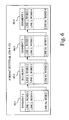
- FIG. 6 is a diagrammatic representation of a format buffer of the format/transpose mechanism of FIG. 5 .
- embodiments of the invention include both hardware and electronic components or modules that, for purposes of discussion, may be illustrated and described as if the majority of the components were implemented solely in hardware.
- the electronic based aspects of the invention may be implemented in software.
- a plurality of hardware and software-based devices, as well as a plurality of different structural components may be utilized to implement the invention.
- the specific mechanical configurations illustrated in the drawings are intended to exemplify embodiments of the invention and that other alternative mechanical configurations are possible.
- Imaging system 10 includes an imaging apparatus 12 and a host 14 .
- Imaging apparatus 12 communicates with host 14 via a communications link 16 .
- communications link 16 is used to generally refer to structure that facilitates electronic communication between multiple components, and may operate using wired or wireless technology.
- Communications link 16 may be established by a direct cable connection, wireless connection or by a network connection such as for example an Ethernet local area network (LAN).
- LAN Ethernet local area network
- Imaging apparatus 12 may be, for example, an ink jet printer and/or copier, or an all-in-one (AIO) unit that includes a print engine, a scanner unit, and possibly a fax unit that incorporate multiple functions such as scanning, copying, and printing capabilities in one device.
- An AIO unit is also known in the art as a multifunction machine.
- imaging apparatus 12 includes a controller 18 , a print engine 20 , and a user interface 22 .
- Print engine 20 may utilize ink jet technology, or other printing technology consistent with this disclosure.
- Imaging apparatus 12 may communicate with host 14 via a standard communication protocol, such as for example, universal serial bus (USB), Ethernet or IEEE 812.1x.
- USB universal serial bus
- Ethernet IEEE 812.1x
- controller 18 communicates with print engine 20 via a communications link 24 .
- Controller 18 communicates with user interface 22 via a communications link 26 .
- Communications links 24 and 26 may be established, for example, by using standard electrical cabling or bus structures, or by wireless connection.
- Host 14 may be, for example, a personal computer including an input/output (I/O) device 28 , such as keyboard and display monitor. Host 14 further includes a processor, input/output (I/O) interfaces, memory, such as RAM, ROM, NVRAM, and a mass data storage device, such as a hard drive, CD-ROM and/or DVD units.
- host 14 includes in its memory a software program including program instructions that function as an imaging driver 30 , e.g., printer driver software, for imaging apparatus 12 .
- Imaging driver 30 is in communication with controller 18 of imaging apparatus 12 via communications link 16 . Imaging driver 30 facilitates communication between imaging apparatus 12 and host 14 , and may provide print data to imaging apparatus 12 , and more particularly, to print engine 20 .
- imaging driver 30 may be located in controller 18 of imaging apparatus 12 .
- controller 18 of imaging apparatus 12 may include an imaging driver configured to support a copying function, and/or a fax-print function, and may be further configured to support a printer function.
- the imaging driver may facilitate communication of print data, as determined by a selected print mode, to print engine 20 .
- Controller 18 includes a processor unit and an associated memory 32 , and may be formed as one or more Application Specific Integrated Circuits (ASIC).
- Memory 32 may be, for example, random access memory (RAM), read only memory (ROM), and/or non-volatile RAM (NVRAM).
- RAM random access memory
- ROM read only memory
- NVRAM non-volatile RAM
- memory 32 may be in the form of the seperate electronic memory (e.g., RAM, ROM, and/or NVRAM), a hard drive, a CD or DVD drive, or any memory device convenient for use with controller 18 .
- Controller 18 serves to process print data and to operate print engine 20 during printing.
- print engine 20 may be, for example, an ink jet print engine configured for forming an image on a sheet of print media 34 , such as a sheet of paper, transparency or fabric.
- Print engine 20 may include, for example, a reciprocating printhead carrier 36 that carries at least one ink jet printhead 38 , and may be mechanically and electrically configured to mount, carry and facilitate multiple cartridges, such as a monochrome printhead cartridge and/or one or more color printhead cartridges, each of which includes a respective printhead 38 .
- printhead carrier 36 may carry four printheads, one printhead for each of cyan, magenta, yellow and black.
- a single printhead, such as printhead 38 may include multiple ink jetting arrays, with each array associated with one color of a plurality of colors of ink.
- printhead 38 may include cyan, magenta, and yellow nozzle arrays for respectively ejecting full strength cyan (C) ink, full strength magenta (M) ink and yellow (Y) ink.
- printhead 38 may include dilute colors, such as dilute cyan (c), dilute magenta (m), etc.
- dilute is used for convenience to refer to a ink that does not have a luminance intensity as high as that associated with a corresponding full strength ink of substantially the same chroma, and such dilute inks may be, for example, either dye based or pigment based.
- FIG. 2 illustrates an exemplary nozzle configuration of printhead 38 , including a monochrome nozzle array 40 for ease of discussion.
- Printhead carrier 36 is controlled by controller 18 to move printhead 38 in a reciprocating manner along a bi-directional scan path 42 , which will also be referred to herein as horizontal direction 42 .
- Each left to right, or right to left movement of printhead carrier 36 and printhead 38 along bi-directional scan path 42 over sheet of print media 34 is referred to herein as a pass.
- the area traced by printhead 38 over sheet of print media 34 for a given pass is referred to herein as a swath, such as for example, swath 44 as shown in FIG. 2 .
- Each swath 44 includes a plurality of rasters, i.e., print lines.
- nozzle array 40 includes a plurality of ink jetting nozzles 46 and associated printhead logic 48 . Also associated with each nozzle of the plurality of ink jetting nozzles 46 is an actuator (not shown), e.g., a resistive heater, which when energized ejects ink from a respective nozzle.
- Printhead logic 48 receives transposed print data, e.g., via a DMA operation invoked by controller 18 transferred through communications link 24 , from memory 32 , and delivers the transposed print data to the respective nozzles of the plurality of nozzles 46 during a printing operation.
- the nozzle size may be, but need not be, the same size.
- a swath height 50 of swath 44 corresponds to the distance between the uppermost and lowermost of the nozzles of printhead 38 .
- a monochrome nozzle array 40 may be easily applied to color printing, e.g., where printhead 38 is a color printhead including multiple arrays representing a plurality of primary full strength colors and/or dilute colors of ink.
- a data conversion mechanism 52 is used to convert the input color space data into data compatible with print engine 20 . More particularly, in accordance with an embodiment of the present invention, data conversion mechanism 52 receives the input color space data and outputs CMY and K data, formatted and transposed, for accumulation in memory 32 , which in turn may be accessed via a DMA operation performed by controller 18 to retrieve one or more full swaths of data for use by each printhead 38 during a printing operation.
- the input color space may be, for example, YC b C r (luminance, chrominance-blue, chrominance-red) color space, RGB (red, green, blue) color space, etc.
- Data conversion mechanism 52 may be located in imaging driver 30 of host 14 , in controller 18 of imaging apparatus 12 , or a portion of data conversion mechanism 52 may be located in each of imaging driver 30 and controller 18 .
- Data conversion mechanism 52 includes a color space conversion mechanism 54 , a halftoning mechanism 56 , and a format/transpose mechanism 58 .
- Each of color space conversion mechanism 54 , halftoning mechanism 56 , and format/transpose mechanism 58 may be implemented in software, firmware, hardware, or a combination thereof, and may be in the form of program instructions and associated data arrays and/or lookup tables.
- color space conversion mechanism 54 takes signals from one color space domain and converts them into signals of another color space domain for each image generation.
- color conversion may take place to convert from a light-generating color space domain of, for example, a color display monitor that utilizes primary colors red (R), green (G) and blue (B) to a light-reflective color space domain of, for example, a color printer that utilizes colors, such as for example, cyan (C, c), magenta (M, m), yellow (Y) and black (K).
- input color space data such as the RGB output from an application executed on host 14 or generated by a scanner, is supplied to color space conversion mechanism 54 to generate continuous tone data.
- Color space conversion mechanism 54 is communicatively coupled to halftoning mechanism 56 .
- Halftoning mechanism 56 processes the continuous tone data using a halftoning algorithm to generate halftone image data as an eventual pattern of dots to be placed on a sheet of print media as a result of the printing process.
- Halftoning mechanism 56 is communicatively coupled to format/transpose mechanism 58 .
- Format/transpose mechanism 58 processes the halftone image data supplied by halftoning mechanism 56 .
- the general operation of format/transpose mechanism 58 will be described with respect to the flowchart of FIG. 4 depicting a method of generating image data, including performing a combined format and transpose operation.
- a set of data blocks corresponding to a portion of the halftone image data representing an image to be printed is generated. Due to limitations on the amount of data that may be processed at any one time by format/transpose mechanism 58 , format/transpose mechanism 58 essentially divides the halftone image data into a plurality of data blocks along a given raster.
- the set of data blocks represent a portion, e.g., one or more data blocks but less than all, of the plurality of data blocks needed to process all of the halftone image data.
- each block may be 64 bits (rasters) high and 32 bits wide. Assuming in this example that a word is 32 bits, then each block contains 64 32 bit words.
- format/transpose mechanism 58 processes the set of data blocks to perform a formatting operation, e.g., print start determination, shingling level (i.e., printing pass determination), etc., on the set of data blocks to generate a set of formatted data blocks.
- a formatting operation e.g., print start determination, shingling level (i.e., printing pass determination), etc.
- format/transpose mechanism 58 then performs a transposing operation on each respective formatted data block in the set of data blocks, to generate a set of transposed data blocks, prior to storage of the formatted and transposed data in memory 32 .
- the transposing operation rearranges the formatted data to accommodate the particular printhead logic of the printhead that is to perform the printing operation, e.g., printhead 38 .
- Format/transpose mechanism 58 is communicatively coupled to memory 32 .
- operations 102 and 104 represent a combined format and transpose operation.
- the set of transposed data blocks is then stored in memory 32 for eventual use by printhead(s) 38 of print engine 20 in printing the swaths of print data that form the image on the sheet of print media 34 .
- FIG. 5 is a block diagram of an exemplary configuration of format/transpose mechanism 58 .
- Format/transpose mechanism 58 includes a DMA (direct memory access) interface 60 , a format mechanism 62 , a format state LUT (lookup table) 64 , a format buffer 66 , a transpose mechanism 68 and a transpose array 70 .
- DMA direct memory access
- format/transpose mechanism 58 may be implemented as logic blocks in an ASIC.
- the arrowed lines in FIG. 5 generally indicate the direction of data and/or instruction flow.
- DMA interface 60 is communicatively coupled to format mechanism 62 and is communicatively coupled to transpose mechanism 68 .
- Format mechanism 62 is communicatively coupled to transpose mechanism 68 .
- Format state LUT (lookup table) 64 is communicatively coupled to format mechanism 62 .
- Transpose array 70 is communicatively coupled to transpose mechanism 68 .
- Format buffer 66 is communicatively coupled to format mechanism 62 and is communicatively coupled to transpose mechanism 68 .
- DMA interface 60 is a bi-directional interface which retrieves input data from memory in halftoning mechanism 56 in an In-Burst operation, and outputs transposed image data to memory 32 in an Out-burst operation.
- DMA interface 60 supplies blocks of data retrieved from halftone memory in multi-word In-Bursts to format mechanism 62 .
- the input to format mechanism 62 is controlled by the DMA interface 60 .
- DMA interface 60 retrieves transposed blocks of data via transpose mechanism 68 in a multi-word Out-Burst operation.
- format mechanism 62 has access to format state LUT 64 , which may be implemented in SRAM (static random access memory) for storing state information between blocks of data.
- format mechanism 62 controls format buffer 66 , which holds blocks of formatted data before it is passed to transpose mechanism 68 .
- Format state LUT 64 assists format mechanism 62 during a format operation by storing configuration information or processing requirements for each line of data in format buffer 66 , including keeping track of data blocks and their location within the various segments of format buffer 66 . For instance, one configuration might be whether the data in a given line is 2 bits per pixel or 1 bit per pixel. Another requirement may be that the data has to be shifted by a number of pixels to align with a print-head nozzle correctly. Each line can be unique and thus a configuration word per line is desirable. In one embodiment, for example, format state LUT 64 may be a 64 ⁇ 93 bit SRAM so as to allow for a 93-bit configuration word per line.
- Format buffer 66 may be implemented as a 256 ⁇ 32 bit SRAM buffer.
- Format mechanism 62 utilizes format buffer 66 by dividing format buffer 66 into a plurality of block-sized segments, e.g., segments 66 - 1 , 66 - 2 , 66 - 3 , and 66 - 4 .
- each block-sized segment is 64 ⁇ 32 bits. This allows, for example, during a format operation the handling of 64 lines of four 32 bit word data (64 words total) as four blocks of 64 line data, with each line in each block containing one 32 bit word.
- Each data block of the four data blocks is accumulated in a respective segment of the plurality of block-sized segments 66 - 1 , 66 - 2 , 66 - 3 , and 66 - 4 of format buffer 66 .
- Transpose mechanism 68 has access to format buffer 66 when such access is granted by format mechanism 62 , and transpose mechanism 68 utilizes transpose array 70 during a transpose operation.
- transpose array 70 may be utilized by transpose mechanism 68 during a rotation of the formatted data retrieved from format buffer 66 from a line-read-in orientation to a columnar-read-out orientation.
- Transpose mechanism 68 may utilize each of the 64 ⁇ 32 buffer segments 66 - 1 , 66 - 2 , 66 - 3 or 66 - 4 , to create 32-two word bursts output at a time.
- transpose mechanism 68 reads the first 32 words of a given block from the corresponding buffer segment of format buffer 66 , transposes those first 32 words of the block, and places the first transposed 32 words back into the corresponding buffer segment of format buffer 66 , i.e., over the first 32 words of format buffer 66 .
- transpose mechanism 68 reads the next 32 words of the given block from format buffer 66 , transposes those 32 words of the block, and places those transposed 32 words back into the corresponding buffer segment of format buffer 66 , i.e., over the second 32 words of format buffer 66 .
- the second transpose operation there are 32-two word bursts available to send to main memory 32 in an Out-Burst operation. Because the transposed data will not be contiguous in memory, it will take 32 separate bursts in this example.
- Table 1 illustrates Burst sizes versus time tradeoffs in a given format/transpose mechanism, such as format/transpose mechanism 58 . This correlates to a cost versus performance (e.g., time) tradeoff, since the burse size is dependent of the SRAM memory size (e.g., the larger the SRAM, the larger the Burst size that may be accommodated), and as the size of the SRAM increases there is a corresponding increase in cost.
- SRAM memory size e.g., the larger the SRAM, the larger the Burst size that may be accommodated
- Those skilled in the art will recognize that other combinations not listed in Table 1 could be implemented, if desired.
- format buffer 66 is a 256 ⁇ 32 bit SRAM buffer
- format state LUT 64 is a 64 ⁇ 93 bit SRAM LUT
- transpose array 70 is a 32 ⁇ 32 bit SRAM array, which allows for 4 words in (In-Burst) and 2 words out (Out-Burst) during DMA accesses before format and after transpose, resulting in a 1.27 second process time.
- the best performance target presented in Table 1 utilizes 4 words In-Burst for the format operation and 5 words Out-Burst from the transpose operation, with the use of a format state LUT.
- format/transpose mechanism 58 would use a 640 ⁇ 32 bit format buffer 66 and a 160 ⁇ 93 bit format state LUT 64 , resulting in a 22 percent increase in performance with a 147 percent larger SRAM requirement compared to the previous embodiment having a 256 ⁇ 32 bit SRAM format buffer and a 64 ⁇ 93 bit SRAM format state LUT.
Abstract
Description
| TABLE 1 |
| Burst Size vs. Time |
| In-Burst to | 4 | 4 | 8 | 8 | 4 | 4 | 8 | 8 | 4 | 4 |
| Format Buffer | ||||||||||
| 66 (words) | ||||||||||
| Out-Burst from | 5 | 5 | 2 | 2 | 2 | 2 | 1 | 1 | 1 | 1 |
| Format Buffer | ||||||||||
| 66 (words) | ||||||||||
| Format State | No | Yes | No | Yes | No | Yes | No | Yes | No | Yes |
| |
||||||||||
| Time (seconds) | 1.12 | 1 | 1.16 | 1.04 | 1.38 | 1.27 | 1.55 | 1.49 | 1.83 | 1.71 |
Claims (16)
Priority Applications (1)
| Application Number | Priority Date | Filing Date | Title |
|---|---|---|---|
| US11/456,651 US8023144B2 (en) | 2006-07-11 | 2006-07-11 | Method for generating transposed image data |
Applications Claiming Priority (1)
| Application Number | Priority Date | Filing Date | Title |
|---|---|---|---|
| US11/456,651 US8023144B2 (en) | 2006-07-11 | 2006-07-11 | Method for generating transposed image data |
Publications (2)
| Publication Number | Publication Date |
|---|---|
| US20080013119A1 US20080013119A1 (en) | 2008-01-17 |
| US8023144B2 true US8023144B2 (en) | 2011-09-20 |
Family
ID=38948949
Family Applications (1)
| Application Number | Title | Priority Date | Filing Date |
|---|---|---|---|
| US11/456,651 Active 2030-05-18 US8023144B2 (en) | 2006-07-11 | 2006-07-11 | Method for generating transposed image data |
Country Status (1)
| Country | Link |
|---|---|
| US (1) | US8023144B2 (en) |
Cited By (2)
| Publication number | Priority date | Publication date | Assignee | Title |
|---|---|---|---|---|
| US9542732B2 (en) | 2015-04-03 | 2017-01-10 | Cognex Corporation | Efficient image transformation |
| US10275863B2 (en) * | 2015-04-03 | 2019-04-30 | Cognex Corporation | Homography rectification |
Families Citing this family (1)
| Publication number | Priority date | Publication date | Assignee | Title |
|---|---|---|---|---|
| JP6316330B2 (en) * | 2015-04-03 | 2018-04-25 | コグネックス・コーポレーション | Homography correction |
Citations (2)
| Publication number | Priority date | Publication date | Assignee | Title |
|---|---|---|---|---|
| US4741045A (en) * | 1983-09-23 | 1988-04-26 | Dest Corporation | Optical character isolation system, apparatus and method |
| US20050046653A1 (en) * | 2003-09-03 | 2005-03-03 | Yoshirou Yamazaki | Inkjet recording apparatus and image forming method |
-
2006
- 2006-07-11 US US11/456,651 patent/US8023144B2/en active Active
Patent Citations (2)
| Publication number | Priority date | Publication date | Assignee | Title |
|---|---|---|---|---|
| US4741045A (en) * | 1983-09-23 | 1988-04-26 | Dest Corporation | Optical character isolation system, apparatus and method |
| US20050046653A1 (en) * | 2003-09-03 | 2005-03-03 | Yoshirou Yamazaki | Inkjet recording apparatus and image forming method |
Cited By (2)
| Publication number | Priority date | Publication date | Assignee | Title |
|---|---|---|---|---|
| US9542732B2 (en) | 2015-04-03 | 2017-01-10 | Cognex Corporation | Efficient image transformation |
| US10275863B2 (en) * | 2015-04-03 | 2019-04-30 | Cognex Corporation | Homography rectification |
Also Published As
| Publication number | Publication date |
|---|---|
| US20080013119A1 (en) | 2008-01-17 |
Similar Documents
| Publication | Publication Date | Title |
|---|---|---|
| JP3829508B2 (en) | Image processing apparatus, image processing method, and printing apparatus | |
| JP2004046339A (en) | Control of a plurality of printers | |
| US7075679B2 (en) | Image processing apparatus and method, and printing method and apparatus | |
| US7497538B2 (en) | Method of multipass printing using a plurality of halftone patterns of dots | |
| JP4724042B2 (en) | Color printing method | |
| US9083925B2 (en) | Image processing apparatus and method therefor | |
| JP5957886B2 (en) | Data generator for printing | |
| US20060268297A1 (en) | Method for constructing a lookup table for converting data from a first color space to a second color space | |
| US7557954B2 (en) | Fast color interpolation | |
| US8023144B2 (en) | Method for generating transposed image data | |
| JP4003046B2 (en) | PRINT CONTROL DEVICE, PRINT CONTROL METHOD, PRINT SYSTEM, PRINT CONTROL PROGRAM, AND MEDIUM CONTAINING PRINT CONTROL PROGRAM | |
| EP1033257A2 (en) | Compensation for print-direction induced hue shift using depletion of pixels | |
| JP4837937B2 (en) | Inkjet printer and printer driver | |
| JP5720192B2 (en) | Printing device | |
| US7452047B2 (en) | Method of printing using error diffused shingling masks | |
| US7158262B2 (en) | Multi-level error diffusion apparatus and method of using same | |
| JP2005067054A (en) | Discharge control of improved ink | |
| US8797593B2 (en) | Image processing apparatus and image processing method | |
| US8279478B2 (en) | Printing system, printing apparatus and image-printing method for suppressing image quality degradation | |
| US7140710B2 (en) | Dot management for an imaging apparatus | |
| US20100033757A1 (en) | Image Processing Device, Print Data Generating Method, and Recording Medium | |
| EP0997840A2 (en) | Multi-level pixel density reduction for printers | |
| US20090135439A1 (en) | Method And Apparatus For Printing A High Resolution Image With A Printhead In A Multi-Pass Printing Mode | |
| JP2005014488A (en) | Method of controlling ejection of improvement ink | |
| JP6172257B2 (en) | Printing device |
Legal Events
| Date | Code | Title | Description |
|---|---|---|---|
| AS | Assignment |
Owner name: LEXMARK INTERNATIONAL, INC., KENTUCKY Free format text: ASSIGNMENT OF ASSIGNORS INTEREST;ASSIGNORS:CASE, CHRISTOPHER WILSON;CRUTCHFIELD, DAVID A.;WARD, JAMES ALAN;REEL/FRAME:017910/0273 Effective date: 20060711 |
|
| STCF | Information on status: patent grant |
Free format text: PATENTED CASE |
|
| FPAY | Fee payment |
Year of fee payment: 4 |
|
| AS | Assignment |
Owner name: CHINA CITIC BANK CORPORATION LIMITED, GUANGZHOU BR Free format text: PATENT SECURITY AGREEMENT;ASSIGNOR:LEXMARK INTERNATIONAL, INC.;REEL/FRAME:046989/0396 Effective date: 20180402 |
|
| AS | Assignment |
Owner name: CHINA CITIC BANK CORPORATION LIMITED, GUANGZHOU BR Free format text: CORRECTIVE ASSIGNMENT TO CORRECT THE INCORRECT U.S. PATENT NUMBER PREVIOUSLY RECORDED AT REEL: 046989 FRAME: 0396. ASSIGNOR(S) HEREBY CONFIRMS THE PATENT SECURITY AGREEMENT;ASSIGNOR:LEXMARK INTERNATIONAL, INC.;REEL/FRAME:047760/0795 Effective date: 20180402 |
|
| MAFP | Maintenance fee payment |
Free format text: PAYMENT OF MAINTENANCE FEE, 8TH YEAR, LARGE ENTITY (ORIGINAL EVENT CODE: M1552); ENTITY STATUS OF PATENT OWNER: LARGE ENTITY Year of fee payment: 8 |
|
| MAFP | Maintenance fee payment |
Free format text: PAYMENT OF MAINTENANCE FEE, 12TH YEAR, LARGE ENTITY (ORIGINAL EVENT CODE: M1553); ENTITY STATUS OF PATENT OWNER: LARGE ENTITY Year of fee payment: 12 |
|
| AS | Assignment |
Owner name: LEXMARK INTERNATIONAL, INC., KENTUCKY Free format text: RELEASE BY SECURED PARTY;ASSIGNOR:CHINA CITIC BANK CORPORATION LIMITED, GUANGZHOU BRANCH, AS COLLATERAL AGENT;REEL/FRAME:066345/0026 Effective date: 20220713 |