US8025252B2 - Modular wall construction system for aircraft cabins - Google Patents
Modular wall construction system for aircraft cabins Download PDFInfo
- Publication number
- US8025252B2 US8025252B2 US11/632,755 US63275505A US8025252B2 US 8025252 B2 US8025252 B2 US 8025252B2 US 63275505 A US63275505 A US 63275505A US 8025252 B2 US8025252 B2 US 8025252B2
- Authority
- US
- United States
- Prior art keywords
- wall
- rail
- segment
- modular
- segments
- Prior art date
- Legal status (The legal status is an assumption and is not a legal conclusion. Google has not performed a legal analysis and makes no representation as to the accuracy of the status listed.)
- Expired - Fee Related
Links
- 238000010276 construction Methods 0.000 title claims abstract description 35
- 238000009434 installation Methods 0.000 claims abstract description 16
- 230000015572 biosynthetic process Effects 0.000 claims abstract description 4
- 230000007246 mechanism Effects 0.000 claims description 21
- 230000033001 locomotion Effects 0.000 claims description 7
- 230000000694 effects Effects 0.000 claims description 4
- 230000008439 repair process Effects 0.000 abstract description 2
- 238000005192 partition Methods 0.000 description 5
- 230000010006 flight Effects 0.000 description 4
- 238000010586 diagram Methods 0.000 description 2
- 238000007373 indentation Methods 0.000 description 2
- 210000002105 tongue Anatomy 0.000 description 2
- 241001465754 Metazoa Species 0.000 description 1
- 230000006978 adaptation Effects 0.000 description 1
- 230000008901 benefit Effects 0.000 description 1
- 230000008859 change Effects 0.000 description 1
- 238000004891 communication Methods 0.000 description 1
- 238000006073 displacement reaction Methods 0.000 description 1
- 238000003780 insertion Methods 0.000 description 1
- 230000037431 insertion Effects 0.000 description 1
- 230000008929 regeneration Effects 0.000 description 1
- 238000011069 regeneration method Methods 0.000 description 1
- 230000000284 resting effect Effects 0.000 description 1
- 238000007789 sealing Methods 0.000 description 1
Images


Classifications
-
- B—PERFORMING OPERATIONS; TRANSPORTING
- B64—AIRCRAFT; AVIATION; COSMONAUTICS
- B64D—EQUIPMENT FOR FITTING IN OR TO AIRCRAFT; FLIGHT SUITS; PARACHUTES; ARRANGEMENTS OR MOUNTING OF POWER PLANTS OR PROPULSION TRANSMISSIONS IN AIRCRAFT
- B64D11/00—Passenger or crew accommodation; Flight-deck installations not otherwise provided for
- B64D11/06—Arrangements of seats, or adaptations or details specially adapted for aircraft seats
- B64D11/0606—Arrangements of seats, or adaptations or details specially adapted for aircraft seats with privacy shells, screens, separators or the like
-
- B—PERFORMING OPERATIONS; TRANSPORTING
- B64—AIRCRAFT; AVIATION; COSMONAUTICS
- B64D—EQUIPMENT FOR FITTING IN OR TO AIRCRAFT; FLIGHT SUITS; PARACHUTES; ARRANGEMENTS OR MOUNTING OF POWER PLANTS OR PROPULSION TRANSMISSIONS IN AIRCRAFT
- B64D11/00—Passenger or crew accommodation; Flight-deck installations not otherwise provided for
- B64D11/0023—Movable or removable cabin dividers, e.g. for class separation
Definitions
- the room unit comprises an opening without a sealing.
- the hook-type locking mechanism in the interior of the first and second wall segments comprises a wall recess portion for operation from within the room only.
- FIG. 1 shows a cabin cross section of a commercial aircraft.
- FIG. 2 shows an associated horizontal projection of the cabin of FIG. 1 .
- FIG. 3 shows a vertical section of a room unit according to an exemplary embodiment of the present invention.
- FIG. 5 shows a vertical projection and horizontal projection of a support fitting according to an exemplary embodiment of the present invention.
- FIG. 7 shows a main deck layout in top view.
- FIG. 10 shows two sidewall segments with a hook-type locking mechanism and a tongue-and-groove connection.
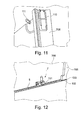
- FIG. 12 shows a clamping element for clamping to a rail according to an exemplary embodiment of the present invention.
- FIG. 13 shows a support fitting according to an exemplary embodiment of the present invention.
- FIG. 14 shows the support fitting of FIG. 13 in its opened position.
- FIG. 1 shows a cabin cross section of a commercial aircraft with a room unit 1 installed in the middle, wherein said room unit 1 comprises the wall segments according to the invention.
- the room unit 1 comprises sidewall segments 2 and corner wall segments 3 . Attachment of the segments is exclusively in the seat rails 5 extending in the cabin floor 4 . Due to the intrinsically stable wall design with mutually supporting wall segments 2 , 3 it may be sufficient to attach the segments in the seat rails 5 . Thus, there may be no need for additional attachment points e.g. on the rib or on the cabin ceiling.
- the segments may be sufficiently high so that the room unit 1 for reasons of visibility does not require a ceiling, a factor which further favours quick installation.
- the arrow in the drawing indicates the optional installation of passenger seats 12 instead of the room unit 1 .
- a greater or lesser number of connectors 8 , 9 , 10 may be provided.
- a tongue-and-groove connection 8 may ensure that the individual wall segments 2 , 3 or 2 , 2 are positioned in one plane. For reasons relating to installation, the groove provides vertical play 81 .
- the non-positive locking connection of the wall segments 2 , 3 is, according to this exemplary embodiment of the present invention, by way of hook-type elements 9 or/and fastening fittings 10 , depending on the type of load. For better stability of the upper edge of the wall, in the diagram the fastening fitting 10 may be embedded in a thick part 11 that goes all around.
- FIG. 4 shows the horizontal projection associated with FIG. 3 .
- the corner wall segment 3 comprises two support fittings 6 .
- an additional support fitting 6 may be installed in a longer limb of the corner segment 3 .
- the drawing shows the wall segments 2 located along the rails 5 with two support fittings 6 and one clamping element 7 .
- the wall segment 2 which is installed across the former, is not connected to the rails 5 so that in this exemplary embodiment of the present invention, the elements 6 and 7 are not installed.
- the connecting elements 6 , 7 may also be selected in a changed arrangement; at any rate a stable structure and fast installation is ensured in this way.
- the drawing also shows that the spacing among the connecting elements 6 , 7 corresponds with the hole spacing of the rails 5 .
- FIG. 5 shows a vertical and a horizontal projection as well as the function of the support fitting 6 as a connection between the wall 2 , 3 and the rail 5 .
- the support base 61 rests against the top of the rail 5 while the guiding pin 62 takes up the space of a rail borehole 51 , thus acting as a safety mechanism against displacement in the floor plane 4 .
- the support fitting 6 may, for example, be screwed to the wall 2 , 3 or may be attached elsewhere (e.g. pushed from below with dovetail into the wall 2 , 3 ) so as to allow quick de-installation of the fitting if there is a cross wall.
- the clamping element 7 which is not shown in detail in the diagram, comprises a simple mechanism for moving the lifting pin 71 horizontally and vertically, with the clamping element 7 being operated by way of a manual lever 73 (e.g. an axially slidable clamp handle).
- a manual lever 73 e.g. an axially slidable clamp handle
- each wall segment may be, for example, 635 mm (e.g. corresponding to a distance of two frame members of the aircraft fuselage) and the height may be, for example, 2100 mm.
- the elements may be of different sizes.
- FIG. 8 shows a cross section of a commercial aircraft body or fuselage, in which the three front wall segments 701 , 702 , 703 can be seen.
- FIG. 9 shows a longitudinal cross section of a commercial aircraft body, depicting possible areas 91 , 92 , into which a modular wall construction system according to an exemplary embodiment of the present invention may be installed.
- the wall segments according to the invention may be used for forming a room unit which may be used as a medical-compartment, an office for doing business, a crew-room for regeneration or stay of crew members during long range flights, as a storage room for storing baggage, as a family room, a children play room, a room for keeping animals, a sofa lounge, for example for first class passengers, or a wellness room or barber shop.
- FIG. 11 shows a box-closing element 110 , which is arranged in an upper region of the sidewall element 705 .
- the box-closing element 110 is adapted for pulling together two segments at their upper side. Furthermore, the box-closing element 110 is adapted for fixing two segments and therefore provides further stability of the room.
- Lever 111 is adapted for locking laterally and may be rotated by 180° for bringing the hook 9 (see FIG. 10 ) from the opened position into the closed position.
- FIG. 12 shows a clamping element for clamping of the segments 705 , 706 to the rail 5 .
- the clamping element 7 comprises a base 131 , which is adapted for engaging with an opening of the rail 5 .
- wall segments 705 , 706 comprise base elements, such as base elements 132 , 133 , for engaging with the holes in the rail and thus defining a fixed position.
Abstract
Description
- 1 Room unit
- 101, 102 Enlarged room units
- 2 Sidewall segment
- 21 Door
- 3 Corner wall segment
- 4 Cabin floor
- 5 Seat rails
- 51 Rail borehole
- 6 Support fitting
- 61 Support base
- 62 Guiding pin
- 7 Clamping element
- 71 Lifting pin
- 72 Clamping plate
- 8 Tongue-and-groove connection
- 81 Vertical play
- 9 Hook-type locking mechanism
- 91 Wall indentation
- 10 Fastening fitting
- 11 Thick part of the wall
- 12 Passenger seats
Claims (17)
Applications Claiming Priority (4)
| Application Number | Priority Date | Filing Date | Title |
|---|---|---|---|
| DE102004035160.0 | 2004-07-20 | ||
| DE102004035160 | 2004-07-20 | ||
| DE102004035160A DE102004035160A1 (en) | 2004-07-20 | 2004-07-20 | Modular wall construction system for aircraft cabins |
| PCT/EP2005/007922 WO2006008151A1 (en) | 2004-07-20 | 2005-07-20 | Modular wall construction system for aircraft cabins |
Publications (2)
| Publication Number | Publication Date |
|---|---|
| US20070295862A1 US20070295862A1 (en) | 2007-12-27 |
| US8025252B2 true US8025252B2 (en) | 2011-09-27 |
Family
ID=34973021
Family Applications (1)
| Application Number | Title | Priority Date | Filing Date |
|---|---|---|---|
| US11/632,755 Expired - Fee Related US8025252B2 (en) | 2004-07-20 | 2005-07-20 | Modular wall construction system for aircraft cabins |
Country Status (10)
| Country | Link |
|---|---|
| US (1) | US8025252B2 (en) |
| EP (1) | EP1768902B1 (en) |
| JP (1) | JP2008506591A (en) |
| CN (1) | CN100447052C (en) |
| AT (1) | ATE393091T1 (en) |
| BR (1) | BRPI0513221A (en) |
| CA (1) | CA2572169A1 (en) |
| DE (2) | DE102004035160A1 (en) |
| RU (1) | RU2381961C2 (en) |
| WO (1) | WO2006008151A1 (en) |
Cited By (2)
| Publication number | Priority date | Publication date | Assignee | Title |
|---|---|---|---|---|
| WO2013074082A1 (en) * | 2011-11-15 | 2013-05-23 | The Boeing Company | Split joint assembly for modules used on mobile platforms |
| US10421550B2 (en) | 2010-01-25 | 2019-09-24 | Airbus Operations Gmbh | Autarkic monument in an aircraft pressure cabin with decentralized operating medium supply and efficient energy conversion |
Families Citing this family (17)
| Publication number | Priority date | Publication date | Assignee | Title |
|---|---|---|---|---|
| DE102005054890B4 (en) * | 2005-11-17 | 2014-08-21 | Airbus Operations Gmbh | An aircraft fuselage structure with a passenger cabin and a mounting structure for fixing interior components in the passenger cabin |
| FR2903662B1 (en) * | 2006-07-12 | 2009-06-12 | Airbus France Sas | REAR CONE OF AN AIRCRAFT. |
| DE102007009849B4 (en) * | 2007-02-28 | 2017-08-17 | Airbus Operations Gmbh | Airplane with a modular cabin element |
| DE202008003772U1 (en) * | 2008-03-18 | 2008-07-03 | Sell Gmbh | Device for detachable floor mounting of cabinets or the like in galleys of aircraft |
| DE102008038806A1 (en) | 2008-08-13 | 2010-02-25 | Airbus Deutschland Gmbh | Pre-assembly and integration of aircraft cabins |
| DE102008039635A1 (en) | 2008-08-25 | 2010-03-04 | Airbus Deutschland Gmbh | Deck arrangement |
| DE102010064100A1 (en) * | 2010-12-23 | 2012-06-28 | Airbus Operations Gmbh | Partition for an aircraft cabin and aircraft |
| US9079668B2 (en) | 2012-02-14 | 2015-07-14 | C&D Zodiac, Inc. | Integrated lavatory galley monument |
| EP3290328B1 (en) * | 2016-09-05 | 2019-07-03 | Airbus Operations GmbH | Door unit for a means of transport |
| GB2555123B (en) * | 2016-10-19 | 2020-04-29 | Thompson Aero Seating Ltd | Passenger seating with partition assembly |
| HU4791U (en) * | 2016-11-23 | 2017-10-30 | Hm Currus Goedoelloei Harcjarmuetechnikai Zrt | Bus structure with modular interior |
| FR3069847B1 (en) * | 2017-08-02 | 2020-09-11 | Airbus Interiors Services | AIRCRAFT WITH A SPECIAL ARRANGEMENT MODULE |
| CN108082495B (en) * | 2017-12-03 | 2021-02-26 | 中国直升机设计研究所 | Air distribution system based on cabin door framework of helicopter cockpit |
| CA3090164A1 (en) * | 2018-02-08 | 2019-08-15 | Dubai Aviation Engineering Projects | Cabin module |
| DE102019117420A1 (en) * | 2019-06-27 | 2020-12-31 | Recaro Aircraft Seating Gmbh & Co. Kg | Aircraft cabin device |
| US11926420B2 (en) * | 2020-05-08 | 2024-03-12 | B/E Aerospace, Inc. | Aircraft cabin partition system |
| US11691732B2 (en) * | 2020-07-10 | 2023-07-04 | B/E Aerospace, Inc. | Modular multiple-egress doors for dual occupancy aircraft passenger suites |
Citations (19)
| Publication number | Priority date | Publication date | Assignee | Title |
|---|---|---|---|---|
| US3294034A (en) * | 1964-06-18 | 1966-12-27 | American Mach & Foundry | Cargo container for airplanes |
| US3480239A (en) * | 1967-02-23 | 1969-11-25 | Tridair Industries | Quick change system |
| US3661434A (en) * | 1970-05-28 | 1972-05-09 | Ralph Alster | Unitary modular shelving structure |
| US3899092A (en) * | 1973-07-03 | 1975-08-12 | Arnold B Nordstrom | Cargo-carrying structural modules |
| US3955700A (en) * | 1975-06-02 | 1976-05-11 | Omni Equipment, Inc. | Freight container |
| US5024398A (en) * | 1989-06-28 | 1991-06-18 | The Boeing Company | Office module for passenger aircraft |
| US5083727A (en) * | 1990-01-02 | 1992-01-28 | The Boeing Company | Aircraft cabin system for selectivley locating interior units |
| US5090639A (en) * | 1989-10-26 | 1992-02-25 | United Parcel Service General Services Co. | Cargo-carrying system for passenger aircraft |
| US5134826A (en) * | 1991-04-23 | 1992-08-04 | Precision Manufacturing, Inc. | Structural panel connector for space dividing system |
| US5218803A (en) * | 1991-11-04 | 1993-06-15 | Wright Jeff A | Method and means for reinforcing a steel stud wall |
| US5540402A (en) * | 1993-08-11 | 1996-07-30 | Carducci; Robert F. | Cargo conversion system for passenger aircraft |
| DE19520959A1 (en) | 1995-06-08 | 1996-12-12 | Albert Muehlenberg Apparatebau | Quick mounting and release fixture |
| US5921629A (en) * | 1994-09-12 | 1999-07-13 | Aircraft Modular Products, Inc. | Aircraft divan |
| US6007025A (en) * | 1996-12-23 | 1999-12-28 | The Boeing Company | Stowable module airplane lavatory |
| FR2810352A1 (en) | 2000-06-15 | 2001-12-21 | Plasteurop Metecno Frigo Syste | Corner post for insulating panel assembly has assembly walls in zone receiving panel hooks which comprise inner longitudinal casing whose outer small side has orifices for passage of hooks |
| US6378825B1 (en) * | 1999-12-29 | 2002-04-30 | General Electric Company | Control and power terminal block quick insert/disconnect |
| US20030071743A1 (en) * | 2001-10-12 | 2003-04-17 | Singapore Technologies Electronics Limited | Aircraft monitoring and incident management system |
| US6581876B2 (en) * | 2001-07-25 | 2003-06-24 | The Boeing Company | Aircraft multi-function overhead space access module |
| DE29825000U1 (en) | 1997-11-10 | 2004-03-04 | Ancra Jungfalk Gmbh & Co. Kg | Device for temporary connection of motor vehicle's seat to retaining rail |
-
2004
- 2004-07-20 DE DE102004035160A patent/DE102004035160A1/en not_active Withdrawn
-
2005
- 2005-07-20 DE DE602005006280T patent/DE602005006280T2/en active Active
- 2005-07-20 AT AT05768287T patent/ATE393091T1/en not_active IP Right Cessation
- 2005-07-20 EP EP05768287A patent/EP1768902B1/en not_active Not-in-force
- 2005-07-20 US US11/632,755 patent/US8025252B2/en not_active Expired - Fee Related
- 2005-07-20 CA CA002572169A patent/CA2572169A1/en not_active Abandoned
- 2005-07-20 WO PCT/EP2005/007922 patent/WO2006008151A1/en active IP Right Grant
- 2005-07-20 BR BRPI0513221-5A patent/BRPI0513221A/en not_active IP Right Cessation
- 2005-07-20 CN CNB2005800242279A patent/CN100447052C/en not_active Expired - Fee Related
- 2005-07-20 RU RU2007101903/11A patent/RU2381961C2/en not_active IP Right Cessation
- 2005-07-20 JP JP2007521898A patent/JP2008506591A/en active Pending
Patent Citations (19)
| Publication number | Priority date | Publication date | Assignee | Title |
|---|---|---|---|---|
| US3294034A (en) * | 1964-06-18 | 1966-12-27 | American Mach & Foundry | Cargo container for airplanes |
| US3480239A (en) * | 1967-02-23 | 1969-11-25 | Tridair Industries | Quick change system |
| US3661434A (en) * | 1970-05-28 | 1972-05-09 | Ralph Alster | Unitary modular shelving structure |
| US3899092A (en) * | 1973-07-03 | 1975-08-12 | Arnold B Nordstrom | Cargo-carrying structural modules |
| US3955700A (en) * | 1975-06-02 | 1976-05-11 | Omni Equipment, Inc. | Freight container |
| US5024398A (en) * | 1989-06-28 | 1991-06-18 | The Boeing Company | Office module for passenger aircraft |
| US5090639A (en) * | 1989-10-26 | 1992-02-25 | United Parcel Service General Services Co. | Cargo-carrying system for passenger aircraft |
| US5083727A (en) * | 1990-01-02 | 1992-01-28 | The Boeing Company | Aircraft cabin system for selectivley locating interior units |
| US5134826A (en) * | 1991-04-23 | 1992-08-04 | Precision Manufacturing, Inc. | Structural panel connector for space dividing system |
| US5218803A (en) * | 1991-11-04 | 1993-06-15 | Wright Jeff A | Method and means for reinforcing a steel stud wall |
| US5540402A (en) * | 1993-08-11 | 1996-07-30 | Carducci; Robert F. | Cargo conversion system for passenger aircraft |
| US5921629A (en) * | 1994-09-12 | 1999-07-13 | Aircraft Modular Products, Inc. | Aircraft divan |
| DE19520959A1 (en) | 1995-06-08 | 1996-12-12 | Albert Muehlenberg Apparatebau | Quick mounting and release fixture |
| US6007025A (en) * | 1996-12-23 | 1999-12-28 | The Boeing Company | Stowable module airplane lavatory |
| DE29825000U1 (en) | 1997-11-10 | 2004-03-04 | Ancra Jungfalk Gmbh & Co. Kg | Device for temporary connection of motor vehicle's seat to retaining rail |
| US6378825B1 (en) * | 1999-12-29 | 2002-04-30 | General Electric Company | Control and power terminal block quick insert/disconnect |
| FR2810352A1 (en) | 2000-06-15 | 2001-12-21 | Plasteurop Metecno Frigo Syste | Corner post for insulating panel assembly has assembly walls in zone receiving panel hooks which comprise inner longitudinal casing whose outer small side has orifices for passage of hooks |
| US6581876B2 (en) * | 2001-07-25 | 2003-06-24 | The Boeing Company | Aircraft multi-function overhead space access module |
| US20030071743A1 (en) * | 2001-10-12 | 2003-04-17 | Singapore Technologies Electronics Limited | Aircraft monitoring and incident management system |
Cited By (2)
| Publication number | Priority date | Publication date | Assignee | Title |
|---|---|---|---|---|
| US10421550B2 (en) | 2010-01-25 | 2019-09-24 | Airbus Operations Gmbh | Autarkic monument in an aircraft pressure cabin with decentralized operating medium supply and efficient energy conversion |
| WO2013074082A1 (en) * | 2011-11-15 | 2013-05-23 | The Boeing Company | Split joint assembly for modules used on mobile platforms |
Also Published As
| Publication number | Publication date |
|---|---|
| EP1768902B1 (en) | 2008-04-23 |
| RU2381961C2 (en) | 2010-02-20 |
| CN100447052C (en) | 2008-12-31 |
| RU2007101903A (en) | 2008-08-27 |
| CA2572169A1 (en) | 2006-01-26 |
| DE602005006280T2 (en) | 2009-05-20 |
| DE602005006280D1 (en) | 2008-06-05 |
| WO2006008151A1 (en) | 2006-01-26 |
| DE102004035160A1 (en) | 2006-02-16 |
| BRPI0513221A (en) | 2008-04-29 |
| JP2008506591A (en) | 2008-03-06 |
| US20070295862A1 (en) | 2007-12-27 |
| ATE393091T1 (en) | 2008-05-15 |
| EP1768902A1 (en) | 2007-04-04 |
| CN1989042A (en) | 2007-06-27 |
Similar Documents
| Publication | Publication Date | Title |
|---|---|---|
| US8025252B2 (en) | Modular wall construction system for aircraft cabins | |
| US8657231B2 (en) | Aircraft cabin bin retrofit | |
| US8534603B2 (en) | System and method for manufacturing a vehicle cabin | |
| US6616098B2 (en) | Mid-level deck for passenger aircraft | |
| US7331545B2 (en) | Aircraft archway | |
| US10933969B2 (en) | Puck attachment mechanism for flexible aircraft configuration | |
| US10494103B2 (en) | Expandable aircraft monument, and aircraft area having an expandable aircraft monument | |
| US8727277B2 (en) | Hold layout device for an aircraft for crew-member rest and aircraft comprising same | |
| US11155353B2 (en) | Flexible aircraft seat configurations | |
| EP3521165B1 (en) | Room partion assemblies, systems, and methods | |
| EP3608226B1 (en) | Toilet arrangement for a vehicle | |
| US20180194473A1 (en) | Flexible foldover seat configurations for emergency egress of aircraft | |
| US11591089B2 (en) | Aircraft cabin comprising a cargo area intended to accommodate passengers | |
| US20230060580A1 (en) | System and method for passenger plane to cargo plane conversion | |
| EP4098564A1 (en) | Resting area systems for an internal cabin of a vehicle |
Legal Events
| Date | Code | Title | Description |
|---|---|---|---|
| AS | Assignment |
Owner name: AIRBUS DEUTSCHLAND GMBH, GERMANY Free format text: ASSIGNMENT OF ASSIGNORS INTEREST;ASSIGNORS:HUPPERICH, GEROLD;KRUBER, KLAUS;DOEBERTIN, OLIVER;AND OTHERS;REEL/FRAME:019637/0286;SIGNING DATES FROM 20070418 TO 20070424 Owner name: AIRBUS DEUTSCHLAND GMBH, GERMANY Free format text: ASSIGNMENT OF ASSIGNORS INTEREST;ASSIGNORS:HUPPERICH, GEROLD;KRUBER, KLAUS;DOEBERTIN, OLIVER;AND OTHERS;SIGNING DATES FROM 20070418 TO 20070424;REEL/FRAME:019637/0286 |
|
| FEPP | Fee payment procedure |
Free format text: PAYOR NUMBER ASSIGNED (ORIGINAL EVENT CODE: ASPN); ENTITY STATUS OF PATENT OWNER: LARGE ENTITY |
|
| ZAAA | Notice of allowance and fees due |
Free format text: ORIGINAL CODE: NOA |
|
| ZAAB | Notice of allowance mailed |
Free format text: ORIGINAL CODE: MN/=. |
|
| AS | Assignment |
Owner name: AIRBUS OPERATIONS GMBH, GERMANY Free format text: CHANGE OF NAME;ASSIGNOR:AIRBUS DEUTSCHLAND GMBH;REEL/FRAME:026360/0849 Effective date: 20090602 |
|
| ZAAA | Notice of allowance and fees due |
Free format text: ORIGINAL CODE: NOA |
|
| STCF | Information on status: patent grant |
Free format text: PATENTED CASE |
|
| FPAY | Fee payment |
Year of fee payment: 4 |
|
| MAFP | Maintenance fee payment |
Free format text: PAYMENT OF MAINTENANCE FEE, 8TH YEAR, LARGE ENTITY (ORIGINAL EVENT CODE: M1552); ENTITY STATUS OF PATENT OWNER: LARGE ENTITY Year of fee payment: 8 |
|
| FEPP | Fee payment procedure |
Free format text: MAINTENANCE FEE REMINDER MAILED (ORIGINAL EVENT CODE: REM.); ENTITY STATUS OF PATENT OWNER: LARGE ENTITY |
|
| LAPS | Lapse for failure to pay maintenance fees |
Free format text: PATENT EXPIRED FOR FAILURE TO PAY MAINTENANCE FEES (ORIGINAL EVENT CODE: EXP.); ENTITY STATUS OF PATENT OWNER: LARGE ENTITY |
|
| STCH | Information on status: patent discontinuation |
Free format text: PATENT EXPIRED DUE TO NONPAYMENT OF MAINTENANCE FEES UNDER 37 CFR 1.362 |
|
| FP | Lapsed due to failure to pay maintenance fee |
Effective date: 20230927 |