US8025354B2 - Sensing objects for printing - Google Patents

Sensing objects for printing Download PDF

Info

Publication number
US8025354B2
US8025354B2 US12/478,678 US47867809A US8025354B2 US 8025354 B2 US8025354 B2 US 8025354B2 US 47867809 A US47867809 A US 47867809A US 8025354 B2 US8025354 B2 US 8025354B2
Authority
US
United States
Prior art keywords
ejection device
drop ejection
conveyor
objects
process direction
Prior art date
Legal status (The legal status is an assumption and is not a legal conclusion. Google has not performed a legal analysis and makes no representation as to the accuracy of the status listed.)
Active, expires
Application number
US12/478,678
Other versions
US20090303266A1 (en
Inventor
Richard J. Baker
William Leathers
Bailey Smith
Roger Therrien
Current Assignee (The listed assignees may be inaccurate. Google has not performed a legal analysis and makes no representation or warranty as to the accuracy of the list.)
Fujifilm Dimatix Inc
Original Assignee
Fujifilm Dimatix Inc
Priority date (The priority date is an assumption and is not a legal conclusion. Google has not performed a legal analysis and makes no representation as to the accuracy of the date listed.)
Filing date
Publication date
Application filed by Fujifilm Dimatix Inc filed Critical Fujifilm Dimatix Inc
Priority to US12/478,678 priority Critical patent/US8025354B2/en
Assigned to FUJIFILM DIMATIX, INC. reassignment FUJIFILM DIMATIX, INC. ASSIGNMENT OF ASSIGNORS INTEREST (SEE DOCUMENT FOR DETAILS). Assignors: THERRIEN, ROGER, BAKER, RICHARD J., LEATHERS, WILLIAM, SMITH, BAILEY
Publication of US20090303266A1 publication Critical patent/US20090303266A1/en
Application granted granted Critical
Publication of US8025354B2 publication Critical patent/US8025354B2/en
Active legal-status Critical Current
Adjusted expiration legal-status Critical

Links

Images

Classifications

    • BPERFORMING OPERATIONS; TRANSPORTING
    • B41PRINTING; LINING MACHINES; TYPEWRITERS; STAMPS
    • B41JTYPEWRITERS; SELECTIVE PRINTING MECHANISMS, i.e. MECHANISMS PRINTING OTHERWISE THAN FROM A FORME; CORRECTION OF TYPOGRAPHICAL ERRORS
    • B41J29/00Details of, or accessories for, typewriters or selective printing mechanisms not otherwise provided for
    • B41J29/38Drives, motors, controls or automatic cut-off devices for the entire printing mechanism
    • B41J29/393Devices for controlling or analysing the entire machine ; Controlling or analysing mechanical parameters involving printing of test patterns
    • BPERFORMING OPERATIONS; TRANSPORTING
    • B41PRINTING; LINING MACHINES; TYPEWRITERS; STAMPS
    • B41JTYPEWRITERS; SELECTIVE PRINTING MECHANISMS, i.e. MECHANISMS PRINTING OTHERWISE THAN FROM A FORME; CORRECTION OF TYPOGRAPHICAL ERRORS
    • B41J11/00Devices or arrangements  of selective printing mechanisms, e.g. ink-jet printers or thermal printers, for supporting or handling copy material in sheet or web form
    • B41J11/0095Detecting means for copy material, e.g. for detecting or sensing presence of copy material or its leading or trailing end
    • BPERFORMING OPERATIONS; TRANSPORTING
    • B41PRINTING; LINING MACHINES; TYPEWRITERS; STAMPS
    • B41JTYPEWRITERS; SELECTIVE PRINTING MECHANISMS, i.e. MECHANISMS PRINTING OTHERWISE THAN FROM A FORME; CORRECTION OF TYPOGRAPHICAL ERRORS
    • B41J11/00Devices or arrangements  of selective printing mechanisms, e.g. ink-jet printers or thermal printers, for supporting or handling copy material in sheet or web form
    • B41J11/008Controlling printhead for accurately positioning print image on printing material, e.g. with the intention to control the width of margins
    • BPERFORMING OPERATIONS; TRANSPORTING
    • B41PRINTING; LINING MACHINES; TYPEWRITERS; STAMPS
    • B41JTYPEWRITERS; SELECTIVE PRINTING MECHANISMS, i.e. MECHANISMS PRINTING OTHERWISE THAN FROM A FORME; CORRECTION OF TYPOGRAPHICAL ERRORS
    • B41J2203/00Embodiments of or processes related to the control of the printing process
    • B41J2203/01Inspecting a printed medium or a medium to be printed using a sensing device

Definitions

  • Ink jet printers are one type of apparatus for depositing drops on a substrate.
  • Ink jet printers typically include an ink path from an ink supply to a nozzle path. The nozzle path terminates in a nozzle opening from which ink drops are ejected.
  • Ink drop ejection is typically controlled by pressurizing ink in the ink path with an actuator, which may be, for example, a piezoelectric deflector, a thermal bubble jet generator, or an electrostatically deflected element.
  • An actuator which may be, for example, a piezoelectric deflector, a thermal bubble jet generator, or an electrostatically deflected element.
  • a typical print assembly has an array of ink paths with corresponding nozzle openings and associated actuators. Drop ejection from each nozzle opening can be independently controlled.
  • each actuator is fired to selectively eject a drop at a specific pixel location of an image as the print assembly and a printing substrate are moved relative to one another.
  • the nozzle openings typically have a diameter of 50 microns or less, e.g. around 25 microns, are separated at a pitch of 100-300 nozzles/inch.
  • a piezoelectric actuator has a layer of piezoelectric material, which changes geometry, or bends, in response to an applied voltage. The bending of the piezoelectric layer pressurizes ink in a pumping chamber located along the ink path.
  • Piezoelectric ink-jet print assemblies are also described in Fishbeck et al U.S. Pat. No. 4,825,227, Hine U.S. Pat. No. 4,937,598, Moynihan et al. U.S. Pat. No. 5,659,346 and Hoisington U.S. Pat. No. 5,757,391, the entire contents of which are hereby incorporated by reference.
  • a printing apparatus including a conveyor capable of moving an object in a process direction, a drop ejection device, a sensor array that substantially spans the conveyor in a cross-process direction that is perpendicular to the process direction, the sensor array being configured to detect a position of the object in the process direction and cross-process direction, and a controller configured to receive position data about the object from the sensor array and to cause the drop ejection device to deposit fluid droplets on the object based on the position of the object on the conveyor.
  • the sensor array can be configured to detect more than one object at a time.
  • the controller can be configured to cause the drop ejection device to deposit fluid droplets on more than one object at a time.
  • the sensor array can be configured to detect a leading edge.
  • the controller can be configured to combine the position data with image data to create print data that is sent to the drop ejection device.
  • the position data and image data can comprise a plurality of scan lines comprising binary data including 1s and 0s, 1 for active and 0 for inactive, and the controller can be configured to combine the position data and image data using an AND function.
  • the apparatus can further include a memory that receives the print data from the controller and sends the print data to the drop ejection device.
  • the apparatus can further include an image database for storing at least one image data that is sent to the controller.
  • the controller can include software configured to determine a center of the object based on the position data and to add the print data to the memory based on the center of the object.
  • the controller can include software configured to determine an angle of the object and to adjust the image data to correspond to the angle of the object.
  • the apparatus can further include a delay mechanism that delays the drop ejection from depositing fluid droplets until the object has traveled from the sensor to the drop ejection device.
  • the drop ejection device can include a plurality of jetting arrays. Each jetting array can include a plurality of modules, each module is configured to deposit a different color ink.
  • the delay mechanism can delay the drop ejection device from depositing ink from each module until the object has reach that module.
  • the sensor array can be a charge coupled device camera.
  • the sensor array can have a resolution that matches a resolution of the drop ejection device.
  • the resolution of the drop eject device can be 100 dpi.
  • the sensor can be stationary relative to the conveyor.
  • the drop ejection device can be stationary relative to the conveyor.
  • an object is moved on a conveyer belt in a process direction, a position of the object in the process direction and cross-process direction, which is perpendicular to the process direction, is detected using a sensor array that substantially spans the conveyor in the cross-process direction, and a drop ejection device is caused to deposit fluid droplets on the object based on the position of the object on the conveyor.
  • the position of the object can be detected by a charged coupled device camera.
  • a resolution of the camera can be matched to a resolution of the drop ejection device.
  • the drop ejection device can be delayed from depositing droplets until the object has reached the drop ejection device.
  • the sensor array can be stationary relative to the conveyor.
  • the drop ejection device can be stationary relative to the conveyor.
  • Position data can be sent to a controller, the position data can be combined with the image data to create print data, and the print data can be sent to the drop ejection device. Further, the print data can be sent to a memory before being sent to the drop ejection device.
  • a printing apparatus includes a conveyor divided into a plurality of lanes for moving objects relative to a drop ejection device, a plurality of sensors including at least one sensor for each lane, the sensors configured to detect a leading edge of an object, a controller configured to receive signals from the plurality of sensors when objects are detected, the controller configured to determine the lane that corresponds to the signal and to send image data to that lane, a memory for receiving image data from the controller, the memory configured to enter the image data into the memory corresponding to the lane and to send the image data to the drop ejection device to deposit fluid droplets on the object moving through the corresponding lane.
  • a plurality of objects are moved on a conveyor belt having a plurality of lanes, an object moving through one of the plurality of lanes is detected using a sensor, after detecting the object, a virtual representation of the object moving on the conveyor is created, and the fluid droplets are deposited on the object in that lane.
  • a printing apparatus capable of printing on objects randomly placed on a conveyor without aligning the objects in lanes.
  • the apparatus does not require lanes to separate rows of objects traveling on a conveyor, which can eliminate the need for expensive registration and alignment equipment. Further, since the objects are not aligned, they do not need to be touched, therefore, the apparatus can print on objects in a deformable state (e.g., wet, soft, uncured, or uncooked), such as cookies prior to baking or cupcakes covered in wet icing.
  • a deformable state e.g., wet, soft, uncured, or uncooked
  • a single datapath can be used rather than multiple datapaths, which can reduce the hardware complexity and cost of the system because less space and power are required.
  • the images can be nested together using an OR function, such that objects on the conveyor can overlap without blocking a portion of an image.
  • the OR function can also be used to print a background pattern on an object.
  • the printing apparatus can print on symmetrical objects that do not have a specific orientation or it can print on asymmetrical objects by detecting the angular orientation of an object and rotating the image to align with the angle of the object.
  • FIG. 1 is a schematic of a printing system with a plurality of lanes and a sensor.
  • FIG. 2 is a schematic of a printing system with a plurality of lanes, a plurality of sensors, and a plurality of controllers.
  • FIG. 3 is a schematic of a printing system with a plurality of lanes, a plurality of sensors, and a single controller.
  • FIG. 3A is a schematic of a memory that receives print data from a controller.
  • FIG. 3B is a schematic of two print data overlaid in the memory.
  • FIG. 3C is a schematic of a web having a plurality of marks that correspond to the locations of a plurality of objects on the web.
  • FIG. 4 is a schematic of a printing system with a conveyor and a sensor array.
  • FIG. 5 is a schematic of a CCD array.
  • FIG. 6 is a schematic of a printing system including software to detect the angular position of an object.
  • FIG. 7 is a schematic of a printing system including a conveyor and sensor array.
  • FIG. 7A is a schematic of the combination of binary data of the pattern data and the virtual image data
  • a printing system 10 includes a conveyor 12 for moving a plurality of objects 14 in a process direction 16 (e.g., Y-direction) to a drop ejection device 18 .
  • the drop ejection device can include a plurality of jetting arrays 20 for depositing fluid droplets on the objects.
  • the conveyor could be divided into a plurality of lanes 22 with a jetting array for each lane.
  • each jetting array can include a plurality of modules 24 , such as four modules for each lane (e.g., one module for each ink color, CMYK).
  • the objects in each lane are aligned in the process direction 16 and the cross-process direction 23 (e.g., X-direction, perpendicular to the process direction). Therefore, only one sensor 26 is needed to cause the drop ejection device to deposit fluid droplets on all four objects.
  • the sensor can detect an object by sensing a leading edge of the object. When the sensor detects an object, the sensor can send a signal to a single controller 28 (e.g., a computer), and the controller sends print data to each of the jetting arrays for each lane.
  • a single controller 28 e.g., a computer
  • FIG. 2 shows a printing apparatus 200 including objects 202 that are divided into lanes 204 , but randomly placed in the process direction 206 . Since the objects in each lane are not aligned with the objects in neighboring lanes, a sensor 208 is needed for each lane. Each lane now has a sensor 208 (S 1 , S 2 , S 3 , and S 4 ) and a controller 210 (C 1 , C 2 , C 3 , and C 4 ). This can add hardware complexity and cost because the system requires more space and power.
  • a single controller can be used by creating a virtual representation of the objects on the conveyor, as shown in the printing apparatus 300 of FIG. 3 .
  • a virtual representation can be created by tracking the movement of a conveyor 302 and using sensors 304 to detect the positions of a plurality of objects 306 on the moving conveyor.
  • an encoder 308 can generate and send timing signals to the single controller 310 representing the physical movement of a conveyor.
  • the sensors can send trigger signals to the controller when an object is detected.
  • the controller uses the timing signals and trigger signals to create a virtual representation of the objects on the conveyor in the memory 312 .
  • the memory can be divided into a plurality of sections 314 , such as four sections as shown in FIG. 3A , that correspond with the number of conveyor lanes.
  • the controller receives a signal from one of the sensors (e.g., S 1 , S 2 , S 3 , or S 4 ), the controller determines which sensor sent the signal and adds image data to the section of the memory that corresponds to that particular lane.
  • the printing system can also include an image database 316 including one or more image data 318 , three image data (star, arrow, and double-sided arrow) are shown in FIG. 3 , that are rotated to provide variability to the printing process.
  • a delay mechanism 320 can also be included to delay the drop ejection device 322 from depositing droplets until the object has traveled from the sensor to the drop ejection device.
  • the encoder can be used to transfer data from the memory to the drop ejection device through a delay mechanism. In the case of a plurality of modules 324 per lane, each color has a different delay constant.
  • the first module can print cyan ink with a delay constant t
  • the second module can print magenta with a delay constant t+1
  • the third module can print yellow ink with a delay constant t+2
  • the fourth module can print black with a delay constant of t+3.
  • Image data can be comprised of scan lines including binary data, 1s and 0s (1 is active, 0 is inactive), meaning the drop ejection device will deposit a fluid droplet where there is a 1 and not deposit a fluid droplet where there is a 0.
  • the memory can be comprised of 1s and 0s populated by the controller. The controller adds image data to the memory, for example, by using an “OR” function.
  • the “OR” function enables the drop ejection device to print complete images without interruption on objects that are next to each other with little or no gap between the objects. For example, two objects are next to each other on a conveyor such that they are touching as they traveling down the conveyor to a drop ejection device.
  • a sensor detects the first object and sends a trigger signal to the controller. Soon after, the sensor detects the second object and sends another trigger signal to the controller.
  • the controller adds a first image data to the memory using the “OR” function.
  • the controller adds the second image data to the memory using an “OR” function, such that if the first image data overlaps with the second image data, then the drop ejection device will print the 1s that are overlapped with 0s.
  • the print data can be added one rasterized scan line at a time or the entire image could be copied into the memory.
  • FIG. 3B shows a virtual representation 326 of two objects close together such that the arrow images 328 overlap.
  • a bottom portion of the first image data 330 overlaps the top portion of the arrow in the second image data 332 .
  • the “OR” function combines the binary data of the two image data, and the memory enters a 1 if a 1 and 0 overlap.
  • the bottom portion of the first image data will not block the top portion of the second image data, and the drop ejection will print both complete images on the corresponding first and second objects.
  • the “OR” function can also be used when printing on objects in which the image space of a neighboring object encroaches on another, such as paper cups 334 that have a tapered conical shape as shown in FIG. 3C . If the objects to be printed on are on a continuous web 336 , then a mark 338 (e.g., head of forms mark) could be placed on the web next to the object to be printed on, and a sensor could detect this mark. The sensor sends a trigger signal to the controller, and the controller can use the “OR” function to overlay the images in the memory as described above.
  • a mark 338 e.g., head of forms mark
  • a sensor array 402 can be used to detect the position of an object 404 in both the process direction 406 and cross-process direction 408 .
  • the sensor array can substantially span the width of the conveyor 410 in the cross-process direction, and the array can be stationary relative to the conveyor. If the sensor array substantially spans the conveyor and is positioned above the conveyor, the sensor array can detect more than one object at a time as shown in FIG. 4 .
  • the sensor array 500 can be a camera 502 (e.g., charge coupled device (CCD) camera), as shown in FIG. 5 and described later in this disclosure.
  • CCD charge coupled device
  • the encoder 412 and sensor array 402 can be used to create a virtual representation 414 of the objects moving on the conveyor.
  • the encoder tracks the movement of the conveyor and the sensor array detects objects on the conveyor and sends position data 416 to the controller 418 .
  • the position data includes the position of the object on the conveyor in both the process direction and cross-process direction.
  • the position data can be a single point (e.g., a leading edge) or a plurality of points representing the entire object.
  • a program can analyze the position data to determine the center of the object.
  • the controller then adds image data to the memory 420 in a space corresponding to the position data. Again the controller can use the “OR” function to add image data to the memory to overlay image data.
  • FIG. 6 shows a printing system 600 that includes software to analyze the position data to identify an angular position of an object 602 .
  • the image data 604 can be rotated to match the angular position of the object, and the rotated image data is entered in the memory 606 .
  • a pattern could be printed on an object as shown in the printing apparatus 700 of FIG. 7 .
  • the sensor 702 array can be used to create a virtual representation 704 of the objects 706 on a conveyor 708 .
  • the pattern data 710 comprised of scan lines N being combined with the scan lines N of the virtual image 711 using an “AND” gate 712 .
  • FIG. 7A shows the binary data of the pattern scan line 716 and virtual image scan line 718 being combined using the “AND” function.
  • the result line 720 “N” is low and the drop ejection device will not deposit a droplet. If the pattern data is repeatable, the data can be restarted at scan line 1 to produce a continuously repeating image pattern.
  • the sensor array described in FIGS. 4 , 6 , and 7 can include a camera 502 , such as a CCD camera.
  • the sensor array 500 can have a resolution similar to the resolution of the drop ejection device.
  • the drop ejection device can include four modules that substantially span the width of the conveyor, each module has 256 jets for a total of (4 ⁇ 256) 1024 jets and the total width of the modules is about 10 inches. Therefore, to match the printing resolution of the drop ejection device, the sensor array needs a resolution of about 100 dpi (1024 jets/10 inches).
  • a CCD camera as shown in FIG.
  • a level conversion 504 can be used to change gray scale camera data into binary data 506 .

Abstract

A printing apparatus including a conveyor capable of moving an object in a process direction, a drop ejection device, a sensor array that substantially spans the conveyor in a cross-process direction that is perpendicular to the process direction, the sensor array being configured to detect a position of the object in the process direction and cross-process direction, and a controller configured to receive position data about the object from the sensor array and to cause the drop ejection device to deposit fluid droplets on the object based on the position of the object on the conveyor.

Description

This application claims the benefit of U.S. Provisional Application No. 61/059,705, filed Jun. 6, 2008, and incorporated herein by reference.
BACKGROUND
Ink jet printers are one type of apparatus for depositing drops on a substrate. Ink jet printers typically include an ink path from an ink supply to a nozzle path. The nozzle path terminates in a nozzle opening from which ink drops are ejected. Ink drop ejection is typically controlled by pressurizing ink in the ink path with an actuator, which may be, for example, a piezoelectric deflector, a thermal bubble jet generator, or an electrostatically deflected element. A typical print assembly has an array of ink paths with corresponding nozzle openings and associated actuators. Drop ejection from each nozzle opening can be independently controlled. In a drop-on-demand print assembly, each actuator is fired to selectively eject a drop at a specific pixel location of an image as the print assembly and a printing substrate are moved relative to one another. In high performance print assemblies, the nozzle openings typically have a diameter of 50 microns or less, e.g. around 25 microns, are separated at a pitch of 100-300 nozzles/inch.
A piezoelectric actuator has a layer of piezoelectric material, which changes geometry, or bends, in response to an applied voltage. The bending of the piezoelectric layer pressurizes ink in a pumping chamber located along the ink path. Piezoelectric ink-jet print assemblies are also described in Fishbeck et al U.S. Pat. No. 4,825,227, Hine U.S. Pat. No. 4,937,598, Moynihan et al. U.S. Pat. No. 5,659,346 and Hoisington U.S. Pat. No. 5,757,391, the entire contents of which are hereby incorporated by reference.
SUMMARY
In one aspect, a printing apparatus including a conveyor capable of moving an object in a process direction, a drop ejection device, a sensor array that substantially spans the conveyor in a cross-process direction that is perpendicular to the process direction, the sensor array being configured to detect a position of the object in the process direction and cross-process direction, and a controller configured to receive position data about the object from the sensor array and to cause the drop ejection device to deposit fluid droplets on the object based on the position of the object on the conveyor.
This and other embodiments can optionally include one or more of the following features. The sensor array can be configured to detect more than one object at a time. The controller can be configured to cause the drop ejection device to deposit fluid droplets on more than one object at a time. The sensor array can be configured to detect a leading edge.
The controller can be configured to combine the position data with image data to create print data that is sent to the drop ejection device. The position data and image data can comprise a plurality of scan lines comprising binary data including 1s and 0s, 1 for active and 0 for inactive, and the controller can be configured to combine the position data and image data using an AND function. The apparatus can further include a memory that receives the print data from the controller and sends the print data to the drop ejection device. The apparatus can further include an image database for storing at least one image data that is sent to the controller.
The controller can include software configured to determine a center of the object based on the position data and to add the print data to the memory based on the center of the object. The controller can include software configured to determine an angle of the object and to adjust the image data to correspond to the angle of the object.
The apparatus can further include a delay mechanism that delays the drop ejection from depositing fluid droplets until the object has traveled from the sensor to the drop ejection device. The drop ejection device can include a plurality of jetting arrays. Each jetting array can include a plurality of modules, each module is configured to deposit a different color ink. The delay mechanism can delay the drop ejection device from depositing ink from each module until the object has reach that module.
The sensor array can be a charge coupled device camera. The sensor array can have a resolution that matches a resolution of the drop ejection device. The resolution of the drop eject device can be 100 dpi. The sensor can be stationary relative to the conveyor. The drop ejection device can be stationary relative to the conveyor.
In one aspect, an object is moved on a conveyer belt in a process direction, a position of the object in the process direction and cross-process direction, which is perpendicular to the process direction, is detected using a sensor array that substantially spans the conveyor in the cross-process direction, and a drop ejection device is caused to deposit fluid droplets on the object based on the position of the object on the conveyor.
This and other embodiments can optionally include one or more of the following features. The position of the object can be detected by a charged coupled device camera. A resolution of the camera can be matched to a resolution of the drop ejection device.
The drop ejection device can be delayed from depositing droplets until the object has reached the drop ejection device. The sensor array can be stationary relative to the conveyor. The drop ejection device can be stationary relative to the conveyor. Position data can be sent to a controller, the position data can be combined with the image data to create print data, and the print data can be sent to the drop ejection device. Further, the print data can be sent to a memory before being sent to the drop ejection device.
In one aspect, a printing apparatus includes a conveyor divided into a plurality of lanes for moving objects relative to a drop ejection device, a plurality of sensors including at least one sensor for each lane, the sensors configured to detect a leading edge of an object, a controller configured to receive signals from the plurality of sensors when objects are detected, the controller configured to determine the lane that corresponds to the signal and to send image data to that lane, a memory for receiving image data from the controller, the memory configured to enter the image data into the memory corresponding to the lane and to send the image data to the drop ejection device to deposit fluid droplets on the object moving through the corresponding lane.
In one aspect, a plurality of objects are moved on a conveyor belt having a plurality of lanes, an object moving through one of the plurality of lanes is detected using a sensor, after detecting the object, a virtual representation of the object moving on the conveyor is created, and the fluid droplets are deposited on the object in that lane.
Potential advantages of the invention may include none, one, or more of the following. A printing apparatus capable of printing on objects randomly placed on a conveyor without aligning the objects in lanes. The apparatus does not require lanes to separate rows of objects traveling on a conveyor, which can eliminate the need for expensive registration and alignment equipment. Further, since the objects are not aligned, they do not need to be touched, therefore, the apparatus can print on objects in a deformable state (e.g., wet, soft, uncured, or uncooked), such as cookies prior to baking or cupcakes covered in wet icing.
By using a camera to map the locations (e.g., X and Y coordinates) of a plurality of objects on the conveyor, a single datapath can be used rather than multiple datapaths, which can reduce the hardware complexity and cost of the system because less space and power are required. The images can be nested together using an OR function, such that objects on the conveyor can overlap without blocking a portion of an image. The OR function can also be used to print a background pattern on an object. The printing apparatus can print on symmetrical objects that do not have a specific orientation or it can print on asymmetrical objects by detecting the angular orientation of an object and rotating the image to align with the angle of the object.
The details of one or more embodiments of the invention are set forth in the accompanying drawings and the description below. Other features, objects, and advantages of the invention will be apparent from the description and drawings, and from the claims.
DESCRIPTION OF DRAWINGS
FIG. 1 is a schematic of a printing system with a plurality of lanes and a sensor.
FIG. 2 is a schematic of a printing system with a plurality of lanes, a plurality of sensors, and a plurality of controllers.
FIG. 3 is a schematic of a printing system with a plurality of lanes, a plurality of sensors, and a single controller.
FIG. 3A is a schematic of a memory that receives print data from a controller.
FIG. 3B is a schematic of two print data overlaid in the memory.
FIG. 3C is a schematic of a web having a plurality of marks that correspond to the locations of a plurality of objects on the web.
FIG. 4 is a schematic of a printing system with a conveyor and a sensor array.
FIG. 5 is a schematic of a CCD array.
FIG. 6 is a schematic of a printing system including software to detect the angular position of an object.
FIG. 7 is a schematic of a printing system including a conveyor and sensor array.
FIG. 7A is a schematic of the combination of binary data of the pattern data and the virtual image data
Like reference symbols in the various drawings indicate like elements.
DETAILED DESCRIPTION
Referring to FIG. 1, a printing system 10 includes a conveyor 12 for moving a plurality of objects 14 in a process direction 16 (e.g., Y-direction) to a drop ejection device 18. The drop ejection device can include a plurality of jetting arrays 20 for depositing fluid droplets on the objects. For example, the conveyor could be divided into a plurality of lanes 22 with a jetting array for each lane. Furthermore, each jetting array can include a plurality of modules 24, such as four modules for each lane (e.g., one module for each ink color, CMYK).
In FIG. 1, the objects in each lane are aligned in the process direction 16 and the cross-process direction 23 (e.g., X-direction, perpendicular to the process direction). Therefore, only one sensor 26 is needed to cause the drop ejection device to deposit fluid droplets on all four objects. The sensor can detect an object by sensing a leading edge of the object. When the sensor detects an object, the sensor can send a signal to a single controller 28 (e.g., a computer), and the controller sends print data to each of the jetting arrays for each lane.
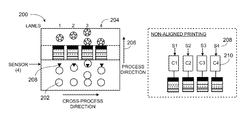
Rather than being aligned in both the process and cross-process directions, the objects could be aligned only in the cross-process direction. FIG. 2 shows a printing apparatus 200 including objects 202 that are divided into lanes 204, but randomly placed in the process direction 206. Since the objects in each lane are not aligned with the objects in neighboring lanes, a sensor 208 is needed for each lane. Each lane now has a sensor 208 (S1, S2, S3, and S4) and a controller 210 (C1, C2, C3, and C4). This can add hardware complexity and cost because the system requires more space and power.
Rather than a plurality of controllers, a single controller can be used by creating a virtual representation of the objects on the conveyor, as shown in the printing apparatus 300 of FIG. 3. A virtual representation can be created by tracking the movement of a conveyor 302 and using sensors 304 to detect the positions of a plurality of objects 306 on the moving conveyor. For example, an encoder 308 can generate and send timing signals to the single controller 310 representing the physical movement of a conveyor. Similarly, the sensors can send trigger signals to the controller when an object is detected. The controller uses the timing signals and trigger signals to create a virtual representation of the objects on the conveyor in the memory 312.
The memory can be divided into a plurality of sections 314, such as four sections as shown in FIG. 3A, that correspond with the number of conveyor lanes. When the controller receives a signal from one of the sensors (e.g., S1, S2, S3, or S4), the controller determines which sensor sent the signal and adds image data to the section of the memory that corresponds to that particular lane.
The printing system can also include an image database 316 including one or more image data 318, three image data (star, arrow, and double-sided arrow) are shown in FIG. 3, that are rotated to provide variability to the printing process. A delay mechanism 320 can also be included to delay the drop ejection device 322 from depositing droplets until the object has traveled from the sensor to the drop ejection device. For example, the encoder can be used to transfer data from the memory to the drop ejection device through a delay mechanism. In the case of a plurality of modules 324 per lane, each color has a different delay constant. FIG. 3 shows four modules per lane, the first module can print cyan ink with a delay constant t, the second module can print magenta with a delay constant t+1, the third module can print yellow ink with a delay constant t+2, and the fourth module can print black with a delay constant of t+3.
Image data can be comprised of scan lines including binary data, 1s and 0s (1 is active, 0 is inactive), meaning the drop ejection device will deposit a fluid droplet where there is a 1 and not deposit a fluid droplet where there is a 0. Similarly, the memory can be comprised of 1s and 0s populated by the controller. The controller adds image data to the memory, for example, by using an “OR” function.
The “OR” function enables the drop ejection device to print complete images without interruption on objects that are next to each other with little or no gap between the objects. For example, two objects are next to each other on a conveyor such that they are touching as they traveling down the conveyor to a drop ejection device. A sensor detects the first object and sends a trigger signal to the controller. Soon after, the sensor detects the second object and sends another trigger signal to the controller. The controller adds a first image data to the memory using the “OR” function. Next, the controller adds the second image data to the memory using an “OR” function, such that if the first image data overlaps with the second image data, then the drop ejection device will print the 1s that are overlapped with 0s. The print data can be added one rasterized scan line at a time or the entire image could be copied into the memory.
FIG. 3B shows a virtual representation 326 of two objects close together such that the arrow images 328 overlap. A bottom portion of the first image data 330 overlaps the top portion of the arrow in the second image data 332. The “OR” function combines the binary data of the two image data, and the memory enters a 1 if a 1 and 0 overlap. Thus, the bottom portion of the first image data will not block the top portion of the second image data, and the drop ejection will print both complete images on the corresponding first and second objects.
The “OR” function can also be used when printing on objects in which the image space of a neighboring object encroaches on another, such as paper cups 334 that have a tapered conical shape as shown in FIG. 3C. If the objects to be printed on are on a continuous web 336, then a mark 338 (e.g., head of forms mark) could be placed on the web next to the object to be printed on, and a sensor could detect this mark. The sensor sends a trigger signal to the controller, and the controller can use the “OR” function to overlay the images in the memory as described above.
Rather than dividing a conveyor into separate lanes to align objects in the cross-process direction, a plurality of objects can be randomly placed on a conveyor so that they are neither aligned in the cross-process direction nor the process direction, as shown in the printing apparatus 400 of FIG. 4. A sensor array 402 can be used to detect the position of an object 404 in both the process direction 406 and cross-process direction 408. The sensor array can substantially span the width of the conveyor 410 in the cross-process direction, and the array can be stationary relative to the conveyor. If the sensor array substantially spans the conveyor and is positioned above the conveyor, the sensor array can detect more than one object at a time as shown in FIG. 4. The sensor array 500 can be a camera 502 (e.g., charge coupled device (CCD) camera), as shown in FIG. 5 and described later in this disclosure.
Referring back to FIG. 4, the encoder 412 and sensor array 402 can be used to create a virtual representation 414 of the objects moving on the conveyor. The encoder tracks the movement of the conveyor and the sensor array detects objects on the conveyor and sends position data 416 to the controller 418. The position data includes the position of the object on the conveyor in both the process direction and cross-process direction. The position data can be a single point (e.g., a leading edge) or a plurality of points representing the entire object. When the position data is a plurality of points, a program can analyze the position data to determine the center of the object. The controller then adds image data to the memory 420 in a space corresponding to the position data. Again the controller can use the “OR” function to add image data to the memory to overlay image data.
FIG. 6 shows a printing system 600 that includes software to analyze the position data to identify an angular position of an object 602. The image data 604 can be rotated to match the angular position of the object, and the rotated image data is entered in the memory 606.
Instead of printing discrete images on individual objects, a pattern could be printed on an object as shown in the printing apparatus 700 of FIG. 7. As described above, the sensor 702 array can be used to create a virtual representation 704 of the objects 706 on a conveyor 708. The pattern data 710 comprised of scan lines N being combined with the scan lines N of the virtual image 711 using an “AND” gate 712. FIG. 7A shows the binary data of the pattern scan line 716 and virtual image scan line 718 being combined using the “AND” function. The drop ejection device 714 will only print when both the pattern data scan line and the virtual image scan line are high (1=active).
If either of the scan lines are low (0=inactive), then the result line 720 “N” is low and the drop ejection device will not deposit a droplet. If the pattern data is repeatable, the data can be restarted at scan line 1 to produce a continuously repeating image pattern.
Referring back to FIG. 5, the sensor array described in FIGS. 4, 6, and 7 can include a camera 502, such as a CCD camera. The sensor array 500 can have a resolution similar to the resolution of the drop ejection device. For example, the drop ejection device can include four modules that substantially span the width of the conveyor, each module has 256 jets for a total of (4×256) 1024 jets and the total width of the modules is about 10 inches. Therefore, to match the printing resolution of the drop ejection device, the sensor array needs a resolution of about 100 dpi (1024 jets/10 inches). For example, a CCD camera as shown in FIG. 5 can have a plurality of elements (e.g., 1000 or more, such as 1024) and optics can be used to focus the width of the products to achieve a particular resolution (e.g., 100 dpi or more, 200 dpi or more, or 300 dpi or more). A level conversion 504 can be used to change gray scale camera data into binary data 506.
A number of embodiments of the invention have been described. Nevertheless, it will be understood that various modifications may be made without departing from the spirit and scope of the invention. Accordingly, other embodiments are within the scope of the following claims.
All references described herein are incorporated by reference for all purposes.

Claims (28)

1. An printing apparatus comprising, a conveyor capable of moving a plurality of objects in a process direction, the plurality of objects placed on the conveyor being neither aligned in the process direction nor a cross-process direction that is perpendicular to the process direction;
a drop ejection device;
a sensor array that substantially spans the conveyor in the cross-process direction and is configured to detect more than one object at a time and to detect a position of each object in the process direction and the cross-process direction; and
a controller configured to receive position data about the plurality of objects from the sensor array and to cause the drop ejection device to deposit fluid droplets on the plurality of objects based on the positions of the plurality of objects on the conveyor.
2. The apparatus of claim 1, wherein the sensor array is configured to detect a leading edge of each object.
3. The apparatus of claim 1, wherein the controller is configured to cause the drop ejection device to deposit fluid droplets on more than one object at a time.
4. The apparatus of claim 1, wherein the sensor array is a charge coupled device camera.
5. The apparatus of claim 1, wherein the sensor array has a resolution that matches a resolution of the drop ejection device. of each object.
6. The apparatus of claim 1, wherein a resolution of the drop ejection device is 100 dpi.
7. The apparatus of claim 1, wherein the sensor array is stationary relative to the conveyor.
8. The apparatus of claim 1, wherein the drop ejection device is stationary relative to the conveyor.
9. The apparatus of claim 1, wherein the controller is configured to combine the position data with image data to create print data that is sent to the drop ejection device.
10. The apparatus of claim 9, wherein the position data and image data comprise a plurality of scan lines comprising binary data including 1s and 0s, 1 for active and 0 For inactive, and the controller configured to combine the position data and image data using an AND function.
11. The apparatus of claim 9, further comprising an image database for storing at least one image data that is sent to the controller.
12. The apparatus of claim 9, wherein the controller comprises software configured to determine an angle of each object and to adjust the image data to correspond to the angle of each object.
13. The apparatus of claim 9, further comprising a memory that receives the print data from the controller and sends the print data to the drop ejection device.
14. The apparatus of claim 13, wherein the controller comprises software configured to determine a center of each object based on the position data and to add the print data to the memory based on the center of each object.
15. The apparatus of claim 13, wherein the controller is configured to add image data to the memory to overlay the image data in a space corresponding to the position data using an “OR” function.
16. The apparatus of claim 1, further comprising a delay mechanism that delays the drop ejection device from depositing fluid droplets on each object until that object has traveled from the sensor to the drop ejection device.
17. The apparatus of claim 16, wherein the drop ejection device comprises a plurality of jetting arrays.
18. The apparatus of claim 17, wherein each jetting array comprises a plurality of modules, each module configured to deposit a different color ink.
19. The apparatus of claim 18, wherein the delay mechanism delays the drop ejection device from depositing ink from each module on each object until that object has have reached that module.
20. A method comprising:
moving a plurality of objects on a conveyor in a process direction;
detecting positions of at least two objects at a time in the process direction and a cross-process direction, which is perpendicular to the process direction, using a sensor array that substantially spans the conveyor in the cross-process direction;
sending position data to a controller; and
causing a drop ejection device to deposit fluid droplets on the at least two objects based on the positions of the at least two objects on the conveyor.
21. The method of claim 20, further comprising delaying the drop ejection device from depositing droplets on each object until that objects has reached the drop ejection device.
22. The method of claim 20, wherein the sensor array is stationary relative to the conveyor.
23. The method of claim 20, wherein the drop ejection device is stationary relative to the conveyor.
24. The method of claim 20, further comprising adding image data to a memory to overlay the image data in a space corresponding to the position data using an “OR” function.
25. The method of claim 20, wherein the positions of the at least two objects are detected by a charge coupled device camera.
26. The method of claim 25, further comprising matching a resolution of the camera to a resolution of the drop ejection device.
27. The method of claim 20, further comprising combining the position data with image data to create print data, and sending the print data to the drop ejection device.
28. The method of claim 27, further comprising sending the print data to a memory before sending the print data to the drop ejection device.
US12/478,678 2008-06-06 2009-06-04 Sensing objects for printing Active 2029-11-07 US8025354B2 (en)

Priority Applications (1)

Application Number Priority Date Filing Date Title
US12/478,678 US8025354B2 (en) 2008-06-06 2009-06-04 Sensing objects for printing

Applications Claiming Priority (2)

Application Number Priority Date Filing Date Title
US5970508P 2008-06-06 2008-06-06
US12/478,678 US8025354B2 (en) 2008-06-06 2009-06-04 Sensing objects for printing

Publications (2)

Publication Number Publication Date
US20090303266A1 US20090303266A1 (en) 2009-12-10
US8025354B2 true US8025354B2 (en) 2011-09-27

Family

ID=41398835

Family Applications (1)

Application Number Title Priority Date Filing Date
US12/478,678 Active 2029-11-07 US8025354B2 (en) 2008-06-06 2009-06-04 Sensing objects for printing

Country Status (6)

Country Link
US (1) US8025354B2 (en)
EP (1) EP2296906B1 (en)
JP (1) JP5485987B2 (en)
KR (1) KR101608428B1 (en)
CN (1) CN102112317B (en)
WO (1) WO2009149163A2 (en)

Cited By (1)

* Cited by examiner, † Cited by third party
Publication number Priority date Publication date Assignee Title
US20190030887A1 (en) * 2017-07-31 2019-01-31 Hp Scitex Ltd. Method and printing system for depositing printing fluid on a sheet of corrugated media

Families Citing this family (6)

* Cited by examiner, † Cited by third party
Publication number Priority date Publication date Assignee Title
JP5176846B2 (en) * 2008-10-03 2013-04-03 セイコーエプソン株式会社 Printing apparatus and printing method
US8395798B2 (en) * 2010-07-15 2013-03-12 Fujifilm Dimatix, Inc. Printing objects using a rolling buffer
CN107364237B (en) * 2013-04-26 2019-09-10 科迪华公司 For the method and apparatus to pad-ink the drop measurement and control of deposits fluid in precision tolerances
JP2015166133A (en) * 2014-03-03 2015-09-24 第一実業ビスウィル株式会社 printer
JP6737616B2 (en) * 2016-03-29 2020-08-12 京セラ株式会社 Print control unit and printing apparatus using the same
JP7188133B2 (en) * 2019-01-28 2022-12-13 コニカミノルタ株式会社 Image forming apparatus and image forming method

Citations (40)

* Cited by examiner, † Cited by third party
Publication number Priority date Publication date Assignee Title
JPS5855253A (en) 1981-09-29 1983-04-01 Ricoh Co Ltd Driving method for electrostriction vibrator in ink jet recorder
JPH0365069A (en) 1989-08-03 1991-03-20 Toto Ltd Driver of piezoelectric actuator
US5408590A (en) 1991-12-09 1995-04-18 Domino Amjet, Inc. Direct ink drop interface board
US5576744A (en) 1992-07-06 1996-11-19 Canon Kabushiki Kaisha Recording apparatus and method compensating for varying gap between recording head and recording medium
JPH09123435A (en) 1995-11-06 1997-05-13 Hitachi Ltd Print head for ink jet recorder
US5668579A (en) 1993-06-16 1997-09-16 Seiko Epson Corporation Apparatus for and a method of driving an ink jet head having an electrostatic actuator
US5784171A (en) 1992-06-24 1998-07-21 Sony Corporation Printing method, printing device, printing head, container vessel for containing printing object and printing method for cassettes
US5959643A (en) 1990-05-08 1999-09-28 Xaar Technology Limited Modular drop-on-demand printing apparatus method of manufacture thereof, and method of drop-on-demand printing
US5975672A (en) 1997-07-24 1999-11-02 Eastman Kodak Company Ink jet printing apparatus and method accommodating printing mode control
US5988784A (en) 1992-11-12 1999-11-23 Canon Kabushiki Kaisha Method and apparatus for recording information with corrected drive timing
US5997124A (en) 1997-03-12 1999-12-07 Raster Graphics Inc. Method and apparatus for drop volume normalization in an ink jet printing operation
US6046822A (en) 1998-01-09 2000-04-04 Eastman Kodak Company Ink jet printing apparatus and method for improved accuracy of ink droplet placement
JP2001010035A (en) 1999-06-25 2001-01-16 Seiko Epson Corp Ink jet recorder
WO2001012444A1 (en) 1999-08-18 2001-02-22 Mikoh Imaging Systems Pty Ltd Multi layer continuous paper printer
WO2001013328A1 (en) 1999-08-16 2001-02-22 Marconi Data Systems Inc. Print engine control system
US6257689B1 (en) 1998-07-31 2001-07-10 Seiko Epson Corporation Printer and method of printing
US6295077B1 (en) 1996-09-06 2001-09-25 Canon Kabushiki Kaisha Image forming apparatus
US6312076B1 (en) 1997-05-07 2001-11-06 Seiko Epson Corporation Driving waveform generating device and method for ink-jet recording head
US6402282B1 (en) 1998-02-12 2002-06-11 Xaar Technology Limited Operation of droplet deposition apparatus
US6422690B1 (en) 1997-07-02 2002-07-23 Xaar Technology Limited Drop on demand ink jet printing apparatus, method of ink jet printing, and method of manufacturing an ink jet printing apparatus
US6460991B1 (en) 1997-09-04 2002-10-08 Xaar Technology Limited Vacuum drums for printing, and duplex printers
US6471315B1 (en) 1997-12-26 2002-10-29 Canon Kabushiki Kaisha Recording apparatus and a recording method
US20020196298A1 (en) 2001-06-22 2002-12-26 Cheng Peter L. Variable ink firing frequency to compensate for paper cockling
US6666537B1 (en) 2002-07-12 2003-12-23 Hewlett-Packard Development Company, L.P. Pen to paper spacing for inkjet printing
US6685297B2 (en) 2001-09-24 2004-02-03 Xerox Corporation Print head alignment method, test pattern used in the method, and a system thereof
US20040028830A1 (en) 2000-06-26 2004-02-12 Bauer Jorg R. Method, system and device for the production of components with a pre-determined surface appearance, in particular for front panels of kitchen units
US20040026212A1 (en) * 2000-10-02 2004-02-12 Rene Maingonnat Method and device to regulating spacing and speed of objects travelling randomly
US20040070791A1 (en) 2002-10-11 2004-04-15 Purushothaman Pattusamy Image data processing
EP1452313A1 (en) 2001-12-03 2004-09-01 Olympus Corporation Image recording apparatus
EP1503326A1 (en) 2003-07-28 2005-02-02 Hewlett-Packard Development Company, L.P. Multicolor-printer and method of printing images
WO2005086715A2 (en) 2004-03-04 2005-09-22 Dimatix, Inc. Morphology-corrected printing
US20060050099A1 (en) 2004-09-08 2006-03-09 Fuji Xerox Co., Ltd. Image recording apparatus
US20060082814A1 (en) 2004-10-15 2006-04-20 Gardner Deane A Printing system architecture
US20060082812A1 (en) 2004-10-15 2006-04-20 Gardner Deane A Data pump for printing
US20060082813A1 (en) 2004-10-15 2006-04-20 Robert Martin Printing system software architecture
US20060082811A1 (en) 2004-10-15 2006-04-20 Gardner Deane A Printing device communication protocol
US20060092437A1 (en) 2004-10-29 2006-05-04 Robert Martin Tailoring image data packets to properties of print heads
US20070236535A1 (en) 2006-04-11 2007-10-11 Richard Baker Ink jet printing
US20070236528A1 (en) * 2006-04-07 2007-10-11 Riso Kagaku Corporation Image forming apparatus
US20070247505A1 (en) 2006-04-20 2007-10-25 Hideyuki Isowa Apparatus and method for printing corrugated cardboard sheets

Family Cites Families (7)

* Cited by examiner, † Cited by third party
Publication number Priority date Publication date Assignee Title
JPH04216989A (en) * 1990-12-17 1992-08-07 Kuwabara Yasunaga Printing
US6476376B1 (en) * 2002-01-16 2002-11-05 Xerox Corporation Two dimensional object position sensor
KR100449019B1 (en) * 2002-08-06 2004-09-18 삼성전자주식회사 apparatus and method for sensing edges of paper in borderless printing mode
JP3753126B2 (en) * 2002-11-29 2006-03-08 ブラザー工業株式会社 Medium edge detection device and image forming apparatus
JP3664163B2 (en) * 2002-12-04 2005-06-22 ブラザー工業株式会社 Printing device
JP2005178289A (en) * 2003-12-22 2005-07-07 Fuji Photo Film Co Ltd Inkjet recorder
AT501432B1 (en) * 2005-02-08 2008-04-15 Durst Phototech Digital Tech INK JET PRINTING DEVICE AND METHOD FOR PRINTING MULTI-COLORED PICTURES

Patent Citations (43)

* Cited by examiner, † Cited by third party
Publication number Priority date Publication date Assignee Title
JPS5855253A (en) 1981-09-29 1983-04-01 Ricoh Co Ltd Driving method for electrostriction vibrator in ink jet recorder
JPH0365069A (en) 1989-08-03 1991-03-20 Toto Ltd Driver of piezoelectric actuator
US5959643A (en) 1990-05-08 1999-09-28 Xaar Technology Limited Modular drop-on-demand printing apparatus method of manufacture thereof, and method of drop-on-demand printing
US5408590A (en) 1991-12-09 1995-04-18 Domino Amjet, Inc. Direct ink drop interface board
US5784171A (en) 1992-06-24 1998-07-21 Sony Corporation Printing method, printing device, printing head, container vessel for containing printing object and printing method for cassettes
US5576744A (en) 1992-07-06 1996-11-19 Canon Kabushiki Kaisha Recording apparatus and method compensating for varying gap between recording head and recording medium
US5988784A (en) 1992-11-12 1999-11-23 Canon Kabushiki Kaisha Method and apparatus for recording information with corrected drive timing
US5668579A (en) 1993-06-16 1997-09-16 Seiko Epson Corporation Apparatus for and a method of driving an ink jet head having an electrostatic actuator
JPH09123435A (en) 1995-11-06 1997-05-13 Hitachi Ltd Print head for ink jet recorder
US6295077B1 (en) 1996-09-06 2001-09-25 Canon Kabushiki Kaisha Image forming apparatus
US5997124A (en) 1997-03-12 1999-12-07 Raster Graphics Inc. Method and apparatus for drop volume normalization in an ink jet printing operation
US6312076B1 (en) 1997-05-07 2001-11-06 Seiko Epson Corporation Driving waveform generating device and method for ink-jet recording head
US6422690B1 (en) 1997-07-02 2002-07-23 Xaar Technology Limited Drop on demand ink jet printing apparatus, method of ink jet printing, and method of manufacturing an ink jet printing apparatus
US5975672A (en) 1997-07-24 1999-11-02 Eastman Kodak Company Ink jet printing apparatus and method accommodating printing mode control
US6460991B1 (en) 1997-09-04 2002-10-08 Xaar Technology Limited Vacuum drums for printing, and duplex printers
US6471315B1 (en) 1997-12-26 2002-10-29 Canon Kabushiki Kaisha Recording apparatus and a recording method
US6046822A (en) 1998-01-09 2000-04-04 Eastman Kodak Company Ink jet printing apparatus and method for improved accuracy of ink droplet placement
US6402282B1 (en) 1998-02-12 2002-06-11 Xaar Technology Limited Operation of droplet deposition apparatus
US6257689B1 (en) 1998-07-31 2001-07-10 Seiko Epson Corporation Printer and method of printing
JP2001010035A (en) 1999-06-25 2001-01-16 Seiko Epson Corp Ink jet recorder
WO2001013328A1 (en) 1999-08-16 2001-02-22 Marconi Data Systems Inc. Print engine control system
WO2001012444A1 (en) 1999-08-18 2001-02-22 Mikoh Imaging Systems Pty Ltd Multi layer continuous paper printer
US20040028830A1 (en) 2000-06-26 2004-02-12 Bauer Jorg R. Method, system and device for the production of components with a pre-determined surface appearance, in particular for front panels of kitchen units
US20040026212A1 (en) * 2000-10-02 2004-02-12 Rene Maingonnat Method and device to regulating spacing and speed of objects travelling randomly
US20020196298A1 (en) 2001-06-22 2002-12-26 Cheng Peter L. Variable ink firing frequency to compensate for paper cockling
US6685297B2 (en) 2001-09-24 2004-02-03 Xerox Corporation Print head alignment method, test pattern used in the method, and a system thereof
EP1452313A1 (en) 2001-12-03 2004-09-01 Olympus Corporation Image recording apparatus
US6666537B1 (en) 2002-07-12 2003-12-23 Hewlett-Packard Development Company, L.P. Pen to paper spacing for inkjet printing
US20040070791A1 (en) 2002-10-11 2004-04-15 Purushothaman Pattusamy Image data processing
EP1503326A1 (en) 2003-07-28 2005-02-02 Hewlett-Packard Development Company, L.P. Multicolor-printer and method of printing images
US7360853B2 (en) 2004-03-04 2008-04-22 Fujifilm Dimatix, Inc. Morphology-corrected printing
WO2005086715A2 (en) 2004-03-04 2005-09-22 Dimatix, Inc. Morphology-corrected printing
EP1732765A2 (en) 2004-03-04 2006-12-20 Spectra, Inc. Morphology-corrected printing
US20080158279A1 (en) 2004-03-04 2008-07-03 Fujifilm Dimatix, Inc. Morphology-corrected printing
US20060050099A1 (en) 2004-09-08 2006-03-09 Fuji Xerox Co., Ltd. Image recording apparatus
US20060082814A1 (en) 2004-10-15 2006-04-20 Gardner Deane A Printing system architecture
US20060082812A1 (en) 2004-10-15 2006-04-20 Gardner Deane A Data pump for printing
US20060082813A1 (en) 2004-10-15 2006-04-20 Robert Martin Printing system software architecture
US20060082811A1 (en) 2004-10-15 2006-04-20 Gardner Deane A Printing device communication protocol
US20060092437A1 (en) 2004-10-29 2006-05-04 Robert Martin Tailoring image data packets to properties of print heads
US20070236528A1 (en) * 2006-04-07 2007-10-11 Riso Kagaku Corporation Image forming apparatus
US20070236535A1 (en) 2006-04-11 2007-10-11 Richard Baker Ink jet printing
US20070247505A1 (en) 2006-04-20 2007-10-25 Hideyuki Isowa Apparatus and method for printing corrugated cardboard sheets

Non-Patent Citations (1)

* Cited by examiner, † Cited by third party
Title
International Search Report and Written Opinion dated Jan. 13, 2010 issued in equivalent PCT Application No. PCT/US2009/046098, 11 pages.

Cited By (3)

* Cited by examiner, † Cited by third party
Publication number Priority date Publication date Assignee Title
US20190030887A1 (en) * 2017-07-31 2019-01-31 Hp Scitex Ltd. Method and printing system for depositing printing fluid on a sheet of corrugated media
CN109318609A (en) * 2017-07-31 2019-02-12 惠普赛天使公司 For depositing the method and print system of printing fluids on corrugated media sheet material
US10434769B2 (en) * 2017-07-31 2019-10-08 Hp Scitex Ltd. Method and printing system for depositing printing fluid on a sheet of corrugated media

Also Published As

Publication number Publication date
EP2296906A4 (en) 2015-04-29
CN102112317B (en) 2013-03-20
EP2296906B1 (en) 2016-07-20
WO2009149163A2 (en) 2009-12-10
KR101608428B1 (en) 2016-04-11
JP5485987B2 (en) 2014-05-07
US20090303266A1 (en) 2009-12-10
CN102112317A (en) 2011-06-29
WO2009149163A3 (en) 2010-03-18
KR20110027761A (en) 2011-03-16
JP2011522721A (en) 2011-08-04
WO2009149163A4 (en) 2010-05-14
EP2296906A2 (en) 2011-03-23

Similar Documents

Publication Publication Date Title
US8025354B2 (en) Sensing objects for printing
CN1868746B (en) Printhead, scanning type inkjet image forming apparatus having the same, and method of performing a printing operation with high resolution
US8721033B2 (en) Method for analyzing image data corresponding to a test pattern effective for fine registration of inkjet printheads in an inkjet printer
US20140111815A1 (en) Printing apparatus and method for correcting print position displacement
US8651615B2 (en) System and method for analysis of test pattern image data in an inkjet printer using a template
US20150367659A1 (en) Printers having encoders for monitoring paper misalignments
JP2007069428A (en) Ink jet recorder
JP6878843B2 (en) Inkjet device
JP2011522721A5 (en)
JP6168735B2 (en) Inkjet recording apparatus and inkjet recording method
US7240987B2 (en) Ink jet printing assembly
JP6519013B2 (en) Ink jet printer
US8191995B2 (en) Printhead for thermal inkjet printing and the printing method thereof
US8736887B2 (en) Printing objects using a rolling buffer
CN113771493A (en) Inkjet print head, inkjet printing apparatus, method and device
US20070132794A1 (en) System and Method For Printing in Substrates
JP7017055B2 (en) Droplet ejection device and droplet ejection adjustment method
JP2019162739A (en) Device and method for discharging liquid
JP2015037845A (en) Recording device, recording method and recording medium
JP2007001137A (en) Inkjet recording apparatus
JP2010036354A (en) Adjusting method

Legal Events

Date Code Title Description
AS Assignment

Owner name: FUJIFILM DIMATIX, INC., NEW HAMPSHIRE

Free format text: ASSIGNMENT OF ASSIGNORS INTEREST;ASSIGNORS:BAKER, RICHARD J.;LEATHERS, WILLIAM;SMITH, BAILEY;AND OTHERS;REEL/FRAME:023063/0243;SIGNING DATES FROM 20090803 TO 20090804

Owner name: FUJIFILM DIMATIX, INC., NEW HAMPSHIRE

Free format text: ASSIGNMENT OF ASSIGNORS INTEREST;ASSIGNORS:BAKER, RICHARD J.;LEATHERS, WILLIAM;SMITH, BAILEY;AND OTHERS;SIGNING DATES FROM 20090803 TO 20090804;REEL/FRAME:023063/0243

STCF Information on status: patent grant

Free format text: PATENTED CASE

CC Certificate of correction
FPAY Fee payment

Year of fee payment: 4

MAFP Maintenance fee payment

Free format text: PAYMENT OF MAINTENANCE FEE, 8TH YEAR, LARGE ENTITY (ORIGINAL EVENT CODE: M1552); ENTITY STATUS OF PATENT OWNER: LARGE ENTITY

Year of fee payment: 8

MAFP Maintenance fee payment

Free format text: PAYMENT OF MAINTENANCE FEE, 12TH YEAR, LARGE ENTITY (ORIGINAL EVENT CODE: M1553); ENTITY STATUS OF PATENT OWNER: LARGE ENTITY

Year of fee payment: 12