US8027315B2 - Antenna diversity - Google Patents
Antenna diversity Download PDFInfo
- Publication number
- US8027315B2 US8027315B2 US10/683,407 US68340703A US8027315B2 US 8027315 B2 US8027315 B2 US 8027315B2 US 68340703 A US68340703 A US 68340703A US 8027315 B2 US8027315 B2 US 8027315B2
- Authority
- US
- United States
- Prior art keywords
- transceiver
- antennas
- antenna
- communicating
- node
- Prior art date
- Legal status (The legal status is an assumption and is not a legal conclusion. Google has not performed a legal analysis and makes no representation as to the accuracy of the status listed.)
- Active, expires
Links
Images


Classifications
-
- H—ELECTRICITY
- H04—ELECTRIC COMMUNICATION TECHNIQUE
- H04W—WIRELESS COMMUNICATION NETWORKS
- H04W40/00—Communication routing or communication path finding
- H04W40/02—Communication route or path selection, e.g. power-based or shortest path routing
-
- H—ELECTRICITY
- H01—ELECTRIC ELEMENTS
- H01Q—ANTENNAS, i.e. RADIO AERIALS
- H01Q1/00—Details of, or arrangements associated with, antennas
- H01Q1/12—Supports; Mounting means
- H01Q1/22—Supports; Mounting means by structural association with other equipment or articles
- H01Q1/24—Supports; Mounting means by structural association with other equipment or articles with receiving set
- H01Q1/241—Supports; Mounting means by structural association with other equipment or articles with receiving set used in mobile communications, e.g. GSM
- H01Q1/246—Supports; Mounting means by structural association with other equipment or articles with receiving set used in mobile communications, e.g. GSM specially adapted for base stations
-
- H—ELECTRICITY
- H01—ELECTRIC ELEMENTS
- H01Q—ANTENNAS, i.e. RADIO AERIALS
- H01Q21/00—Antenna arrays or systems
- H01Q21/06—Arrays of individually energised antenna units similarly polarised and spaced apart
- H01Q21/061—Two dimensional planar arrays
- H01Q21/065—Patch antenna array
-
- H—ELECTRICITY
- H01—ELECTRIC ELEMENTS
- H01Q—ANTENNAS, i.e. RADIO AERIALS
- H01Q21/00—Antenna arrays or systems
- H01Q21/06—Arrays of individually energised antenna units similarly polarised and spaced apart
- H01Q21/20—Arrays of individually energised antenna units similarly polarised and spaced apart the units being spaced along or adjacent to a curvilinear path
- H01Q21/205—Arrays of individually energised antenna units similarly polarised and spaced apart the units being spaced along or adjacent to a curvilinear path providing an omnidirectional coverage
-
- H—ELECTRICITY
- H01—ELECTRIC ELEMENTS
- H01Q—ANTENNAS, i.e. RADIO AERIALS
- H01Q25/00—Antennas or antenna systems providing at least two radiating patterns
-
- H—ELECTRICITY
- H01—ELECTRIC ELEMENTS
- H01Q—ANTENNAS, i.e. RADIO AERIALS
- H01Q9/00—Electrically-short antennas having dimensions not more than twice the operating wavelength and consisting of conductive active radiating elements
- H01Q9/04—Resonant antennas
- H01Q9/0407—Substantially flat resonant element parallel to ground plane, e.g. patch antenna
- H01Q9/0428—Substantially flat resonant element parallel to ground plane, e.g. patch antenna radiating a circular polarised wave
- H01Q9/0435—Substantially flat resonant element parallel to ground plane, e.g. patch antenna radiating a circular polarised wave using two feed points
-
- H—ELECTRICITY
- H04—ELECTRIC COMMUNICATION TECHNIQUE
- H04W—WIRELESS COMMUNICATION NETWORKS
- H04W16/00—Network planning, e.g. coverage or traffic planning tools; Network deployment, e.g. resource partitioning or cells structures
- H04W16/02—Resource partitioning among network components, e.g. reuse partitioning
- H04W16/10—Dynamic resource partitioning
-
- H—ELECTRICITY
- H04—ELECTRIC COMMUNICATION TECHNIQUE
- H04W—WIRELESS COMMUNICATION NETWORKS
- H04W16/00—Network planning, e.g. coverage or traffic planning tools; Network deployment, e.g. resource partitioning or cells structures
- H04W16/24—Cell structures
- H04W16/28—Cell structures using beam steering
Definitions
- This invention relates to methods and apparatus for wireless communication using antenna diversity.
- Radio communication between two terminals is subject to ‘fading’ conditions caused by the constructive addition or cancellation of multiple arriving signals.
- These signals might be comprised of a direct signal from transmitter to receiver, plus various other signals that arrive at slightly later time (and from different angles), having been reflected from other objects in the path between the two terminals.
- Dependent on the exact position of the transmitter and receiver terminal, these multiple arrivals will arrive either in-phase (giving constructive addition) or out of phase (giving signal cancellation).
- This variation in the received signal power is referred to as fading.
- the extent to which the local environment varies determines whether the fade conditions remain constant for a particular placement of the terminals or vary with time.
- a radio link will be deployed with sufficient margin in the received signal strength such that fades due to signal cancellation can be tolerated, while still maintaining sufficient signal power for the transmitted data to be decoded.
- This allowance has a significant impact on the range that can be achieved with the radio link, for a given transmitted power output level. It is therefore highly desirable to identify techniques which allow this fading margin to be minimised.
- the receiving terminal is equipped with two antennas which may be positioned, for example, with a spatial separation that is sufficient for the fading conditions at each antenna to be considered statistically independent.
- the receiver selects the antenna with the best signal. If, for example, there is a 1% probability of fades greater than 20 dB below the mean signal power (averaged over local fading), there is then only a 0.01% chance that both antennas will have above a 20 dB fade. For a constant outage probability, the fade margin can therefore be reduced.
- FIG. 1 shows a transmitter 101 having two antennas 102 , 103 and a receiver 104 having two antennas 105 , 106 .
- TDD time domain duplex
- the same frequency band is used for the reverse link (terminal B to terminal A) as for the forward link (terminal A to terminal B).
- terminal B For a communication that begins with a link from terminal A to terminal B, it is possible for terminal B to benefit from 2-way diversity.
- terminal B can then re-transmit back to terminal A using the same antenna that was found to be best when it was in receiving mode.
- Terminal A then makes a second antenna selection of its two antennas for signal reception.
- terminal A transmits again back to terminal B it can again select the best antenna from reception for use as the transmitting antenna. This can continue indefinitely, iterating towards the best possible selection of all four propagation paths, and adapting to changes in the propagation conditions. This process is referred to herein as the “iterative process”.
- the gain available (i.e. reduction in fade margin) using the iterative process is in many circumstances less than the potential diversity gain if the best of all possible paths were selected.
- the invention seeks to provide a method for wireless communication using antenna diversity which mitigates at least one of the problems of known methods.
- a method of communicating between a first node including a plurality of antennas and a second node comprising the steps of: transmitting a signal from said first node to said second node using each of the plurality of antennas of said first node; at the second node, selecting one of said plurality of antennas for use; and communicating between the two nodes using said selected antenna.
- the method may further comprise the step of: communicating from said second node to said first node an indication of said selected antenna.
- the plurality of antennas may be spatially separated.
- the plurality of antennas may use polarisation diversity.
- the selecting step may comprise the step of: measuring the received strength of said signal; and making said selection based on said measurement.
- the transmitting step may comprise the step of: sequentially transmitting a data packet from each of said plurality of antennas.
- Each said data packet may comprise an indication of which said antenna transmitted said packet.
- the data packet may be a Request to Send frame modified to include said indication.
- the step of communicating may comprise sending a modified Clear to Send frame including said indication.
- the data packet may be a test frame.
- the signal may comprise a data packet, said data packet comprising a plurality of sub-packets, and wherein said transmitting step may comprise: sequentially transmitting a sub-packet from each of said plurality of antennas.
- the data frame may be configured according to a higher layer protocol.
- the indication of said selected antenna may be configured according to a higher layer protocol.
- the step of sequentially transmitting a data packet from each of said plurality of antennas may further comprise: transmitting said data packets at a defined time interval.
- the step of sequentially transmitting a data packet from each of said plurality of antennas may further comprise: transmitting said data packets in a sequence known to said second node.
- a method of optimising communication between a node including a plurality of antennas and a remote node comprising the steps of: transmitting a communication from said node to said remote node using each of the plurality of antennas of said node; receiving a communication from said remote node indicating a selection of one of said plurality of antennas; and communicating with said remote node using said selected antenna.
- a method of optimising communication between a node and a remote node including a plurality of antennas comprising the steps of: receiving a communication from said remote node using each of said plurality of antennas; selecting one of said plurality of antennas for use; and communicating said selection to said remote node.
- a node in a wireless communications network comprising: an antenna for receiving signals from each of a plurality of antennas at a remote node; a processor for determining the optimum signal of said signals from said remote node according to predetermined criteria; and a transmitter for communicating said determination to said remote node.
- a node in a wireless communications network comprising: a transceiver and a processor, wherein a signal is received from each of a plurality of antennas at a remote node at the transceiver, said signal is processed to select an optimum one of said plurality of antennas according to predetermined criteria in the processor and a selection is output to said remote node by the transceiver.
- a wireless network comprising a plurality of nodes as described above.
- a protocol extending a function of the 802.11 Request to Send and Clear to Send frames, such that these frames carry data to identify an antenna used for transmission.
- a higher level protocol utilising 802.11 standard MAC layer frame definitions to test multiple transmitter to receiver propagation while remaining compatible with an 802.11 standard.
- this allows the margin allowed for signal fading to be reduced, thereby increasing the achievable range of the radio link. This allows a significant reduction on the overall number of links required, and hence reduces the system cost.
- the method may be performed by software in machine readable form on a storage medium.
- FIG. 1 is a schematic diagram of a radio link with 2 antennas at one terminal and 2 antennas at a second terminal, indicating the 4 propagation paths between the terminals;
- FIG. 2 is a schematic diagram showing a radio link in which two nodes communicate, each node having 2 antenna channels;
- FIG. 3 is a flow diagram indicating a possible data exchange between two nodes in order to implement the proposed 4-way diversity idea
- FIG. 4 is a flow diagram indicating a second possible data exchange between two nodes in order to implement the proposed 4-way diversity idea
- FIG. 6 is a flow diagram indicating a possible scenario based on the above data exchange in which the second transmitted data is not received successfully;
- FIG. 7 is a graph showing the cumulative probability distribution of signal power due to fading, indicating the potential benefit available from the 4-way diversity technique, in comparison to current 2-way diversity methods;
- FIG. 8 is a graph showing the fade margin that would be allowed for 95% availability of a radio link, for given cross-polar conversion ratios
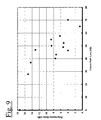
- FIG. 9 is a graph showing trials results indicating the variation of cross-polar conversion ratio with excess path loss above free space propagation.
- Embodiments of the present invention are described below by way of example only. These examples represent the best ways of putting the invention into practice that are currently known to the Applicant although they are not the only ways in which this could be achieved.
- the gain available using the iterative process is in many circumstances less than the potential diversity gain if the best of all possible paths were selected. This difference between the best gain achieved and the ideal is increased further in some circumstances where the two antennas use polarisation diversity, rather than spatial separation. If the signal is transmitted on one polarisation, it must be diffracted or reflected from surfaces in order to become converted to the orthogonal polarisation. If the propagation is unobstructed, this does not occur and an antenna on the same polarisation as the transmitter will receive a greater signal than on an antenna on the orthogonal polarisation. This reduces the receive diversity gain available.
- V and H are examples of two orthogonal polarisations, other pairs of orthogonal polarisations could also be used, such as +45° and ⁇ 45°.
- terminals and nodes are, by way of example only, described as having two antennas, thus providing spatial diversity. It will be apparent to a person skilled in the art that the technique is equally applicable to the situation where two orthogonal polarisations, i.e. providing polarisation diversity. The technique can also be applied to the situation where both spatial and polarisation diversity are used.
- Each antenna may be a single element, a column of elements (as described in a co-pending application detailed below) or any other suitable type.
- the antenna diversity may alternatively be provided by two polarisations of a single antenna element or column of elements.
- the description below refers to terminals each having 2 antennas, thus providing 4-way diversity scheme.
- This technique is however applicable to a first node having M-way antenna diversity (e.g. M antennas) and a second node having N-way antenna diversity, to provide a M ⁇ N-way diversity scheme, (where M is 2 or more and N is at least one).
- transmitting and receiving nodes or terminals. It should be appreciated that both nodes are capable of both transmitting and receiving and this terminology is used by way of explanation only. In the description below it is the “transmitting node” which initiates the communication.
- the nodes may contain separate transmitting and receiving apparatus, or may contain apparatus which is capable of both transmitting and receiving.
- the term ‘transceiver’ is referred to herein as any apparatus capable of transmitting and/or receiving.
- both nodes have two antennas. This can be achieved by the transmitting node making transmissions on both antennas, following an algorithm that is known to the receiving node, so that the receiving node can then select the best of all combinations. This selection can then be communicated to the transmitting node so that data transfer can take place using the optimum antenna pair.
- This technique referred to herein as the “4-way diversity scheme” is described in more detail below.
- the IEEE 802.11 Wireless LAN standard may be used for communication between two nodes within a wireless network. According to this standard, communication uses time domain duplexing on a carrier frequency in the region of 2.4 GHz or 5-6 GHz. This standard is typically intended for communication between an access point and multiple mobile (or portable) terminals. Communication may begin with a request to send (RTS) frame, followed by a clear to send (CTS) frame if the request was received correctly. Once this initial exchange is complete, the two terminals can begin communication. Other terminals, also able to receive these signals, can then determine from receipt of the RTS and/or CTS frames that the frequency is in use and delay their own requests for communication.
- RTS request to send
- CTS clear to send
- the RTS and CTS frames contain an indication of the length of the planned communication, in order that these other terminals can determine how large a delay is required before initiating their own requests.
- the use of RTS and CTS frames is typically invoked when the packet length exceeds a predetermined threshold, but may be used at any time deemed appropriate to optimise the system performance.
- a transmitting terminal having two antennas sends two specially adapted RTS frames, each on an alternate antenna.
- the receiving terminal (which may have one or more antenna) allows time to receive both RTS frames then determines the best receiving antenna for each frame, using a standard 2-way diversity algorithm (e.g. as described above in relation to FIG. 1 ). If the receiving terminal is able to decode both frames successfully, it can select the best combination of receiving and transmitting antennas. It would then return a special CTS frame, containing information to instruct the transmitting terminal which antenna to use for future transmissions. This might be the first or the second antenna as used by the transmitting terminal.
- the transmitting terminal should embed a code (also referred to as a tag or an identifier) in the specially adapted RTS that can be returned by the receiving terminal in order to identify the best antenna for use.
- a code also referred to as a tag or an identifier
- the network nodes retain statistics of the diversity benefits gained from 4-way diversity relative to the iterative process. If little benefit was obtained by use of 4-way diversity relative to the iterated 2-way diversity, the system may then choose to disable the 4-way diversity features and minimise the link setup time. Additionally, the system may choose to only periodically assess which antennas should be used. This has the benefit that if the radio propagation conditions are found to change slowly, the system can reduce the frequency at which the 4-way diversity selection is updated, thereby reducing the signalling overhead. Ideally, the antenna selection for 4-way diversity would be updated at a frequency compatible with the rate of change of the propagation channel. Other techniques for maximising the benefit of this technique whilst minimising the additional overhead are described below.
- RTS and CTS frames may not, in some systems, be used for packet lengths below a certain threshold. It may therefore be advantageous to lower the threshold either permanently or periodically, to force the use of the specially modified RTS and CTS frames.
- Alternative embodiments using other frame formats which avoid the use of the specially modified RTS/CTS exchange are described below.
- FIGS. 3-6 The exchange of information between the two nodes is shown in FIGS. 3-6 and described in more detail below. Common reference numerals have been used where appropriate.
- the network nodes may be Wireless Access and Routing Points (WARPs) arranged in a mesh network.
- WARPs Wireless Access and Routing Points
- WARPs are described in more detail a number of co-pending US Patent Applications including those listed below:
- Nortel reference 15912ID Martin Smith, Chris Ward, Damian Bevan et al.
- FIG. 2 shows a schematic diagram of a wireless link between a first node or terminal 201 called NODE 1 and a second node or terminal 204 called NODE 2 .
- NODE 1 201 has two antennas 202 (A 1 ), 203 (A 2 ) and NODE 2 204 has two antennas 205 (B 1 ), 206 (B 2 ).
- This configuration is by way of example only and this technique is not limited to nodes with two antennas, (the technique requires at least two diverse communication paths, which may utilise spatial and/or polarisation diversity).
- NODE 1 initiates the communication. This is by way of example only.
- the RTS or CTS frames are specially adapted so as to include tag information to denote the antenna selections or requests.
- these may be adaptations of the currently defined RTS or CTS frames, or may be other frames (for example, data frames) which a proprietary system interprets as having the antenna selection and RTS/CTS function.
- the specially adapted RTS and CTS frames may be provided by implementing a higher level protocol with the transmitted user data in an 802.11 frame structure. Systems operating according to this higher level protocol may be configured such that the frames used to implement the 4-way diversity selection also provide an RTS and CTS function.
- FIG. 3 the basic scheme for communication over a wireless link as shown in FIG. 2 is illustrated.
- the transmitting node, NODE 1 sends both RTS frames (steps 301 and 302 ) and then waits for a CTS frame in return.
- NODE 2 receives the two RTS frames on both antennas B 1 and B 2 , and measures the received signal strength of each frame on each antenna (steps 303 and 304 ).
- NODE 2 then sends a CTS frame to NODE 1 advising NODE 1 of the antenna selection which has been made at NODE 2 on the basis of analysis of properties of the received signals (analysis is step 305 and sending of CTS is step 306 ).
- duration fields contained within RTS and CTS frames would be incremented appropriately to allow for the extended transmission time in order to employ the 4-way diversity technique described. It is also assumed that the value of the 802.11 “CTSTimeout” parameter may be set relative to the end of transmission of the second RTS frame.
- FIG. 4 there is shown an alternative scheme to that shown in FIG. 3 , where a separate CTS frame is sent following each RTS frame.
- NODE 2 measures the signal strength or other signal parameter (step 303 ) and sends a CTS acknowledging receipt of the first RTS and requesting trial of the next antenna (step 401 ).
- NODE 1 then sends the second RTS (step 302 ) which is again received and analysed at NODE 2 (step 304 ) and a determination of the best path is made (step 305 ) which is communicated to NODE 1 (step 306 ) in order that communication can start (step 307 ) as in FIG. 3 . If the second RTS is not received at NODE 2 , then NODE 2 responds to NODE 1 after allowing the appropriate RTS and inter-frame spacing to elapse.
- FIG. 5 shows the scenario where the first frame is not decoded successfully (on either antenna at the receiving node, NODE 2 , step 501 ). NODE 1 therefore does not receive a CTS in response to the RTS (step 401 from FIG. 4 is missing). After a period of waiting, NODE 1 may time out (step 502 ) and then proceed to send the RTS from the other antenna A 2 .
- the RTS preferably includes an identifier advising that this RTS is the second antenna trial (step 503 ).
- NODE 2 measures the signal strength of this RTS on both antennas B 1 and B 2 (step 304 ) and sends a CTS to NODE 1 (step 504 ). Communication can then begin using the second antenna (step 307 ).
- FIG. 6 shows a similar scenario, but where the second RTS frame fails to be decoded successfully (step 601 ). If the receiving node, NODE 2 , has been informed that there are only two antennas on NODE 1 , the receiving node can still make a determination of the best path (step 305 ), either because it knows that it has received an RTS which it cannot decode or because it times out waiting for the second RTS (not shown) and can therefore deduce that the second RTS has been sent but not received. In the scenario shown in FIG. 6 , NODE 2 must send the second CTS to NODE 1 within a pre-defined time interval following the sending of the first CTS frame. The timeout at NODE 1 for the arrival of this CTS frame will also be set accordingly.
- NODE 1 transmits the second RTS frame at a defined interval following the arrival of the first CTS frame, such that NODE 2 can use a time counter to determine a time by which the second RTS frame should have been received. It is also assumed that NODE 2 must be provided with information to determine the number of RTS frames to be transmitted and the order with which they will be sent. This allows NODE 2 to determine when to respond, based on the antenna selection that is decoded from any one of the RTS frames received.
- NODE 2 may be informed of how many antennas there are at NODE 1 (i.e. how many RTS frames to expect) and/or that there are no further antennas to trial at the transmitting node, NODE 1 .
- test packets referred to above may be sub-frames (or sub-packets) of a larger frame (or packet).
- the two short test data packets may be the first and second sub-frames of a larger test packet, or the first and second sub-frames of a modified RTS frame.
- the WARP modules are intended to be installed as a mesh network architecture in which data is transferred across between multiple terminals, using a multi-hop or relay structure. Any increase in the range supported by each radio link allows a reduction in the total number of WARPs needed to cover a given area. This reduces the network cost to the operator of the WARP network.
- FIG. 7 shows simulation results, indicating the relative gains of this algorithm.
- the first iteration of the 2-way receive diversity provides a substantial gain (line 702 compared to line 701 ), in terms of a reduced margin that needs to be allowed for fades (e.g., there is a 10% probability that there will be a fade for a single channel of 6.3 dB or more, but at 10% probability, the fade margin for 2-way diversity is reduced to 2.3 dB).
- Further iterations of the 2-way diversity algorithm further reduce the fade margin (lines 703 and 704 ), approaching the best possible case of the 4-way diversity (line 705 ). This graph is shown for the case with complete polarisation mixing, i.e. the cross-polar ratio is 0 dB. The four diversity paths are therefore of equal power.
- the fade margin for 95% availability (5% outage) is shown for varying cross-polar conversion ratio.
- cross-polar conversion ratio is expressed as a negative value, i.e. the ratio of the signal arrival on the orthogonal polarisation to the co-polar signal arrival.
- the 4-way diversity algorithm (line 805 ) has only about 0.6 dB improvement over the best result for three iterations of 2-way diversity (line 804 ).
- the required fade margin for all of the 2-way diversity algorithms increases towards that for a single channel (line 801 ).
- the fade margin for 4-way diversity also increases.
- the fade margin for 4-way diversity is the same as that for 2-way diversity with complete polarisation conversion. In effect, the 4-way diversity technique restores the benefits of 2-way diversity that would otherwise be lost in the absence of polarisation conversion.
- a protocol that allows a radio link with M transmitter antennas and N receiver antennas to achieve M ⁇ N-way diversity gain.
- the protocol extends the definition and function of the 802.11 RTS frames, such that these frames also carry data to identify the antenna used for transmission.
- the nodes in a network determine whether to test multiple transmitting node to receiver propagation paths, based on the anticipated gain and signalling overhead.
- this allows the margin allowed for signal fading to be reduced, thereby increasing the achievable range of the radio link. This allows a significant reduction on the overall number of links required, and hence reduces the system cost.
Abstract
Description
-
- U.S. Patent Application Ser. No. 60/446,617 filed on Feb. 12, 2003 and entitled “System for Coordination of Multi Beam Transit Radio Links for a Distributed Wireless Access System” [15741]
- U.S. Patent Application Ser. No. 60/446,618 filed on Feb. 12, 2003 and entitled “Rendezvous Coordination of Beamed Transit Radio Links for a Distributed Multi-Hop Wireless Access System” [15743]
- U.S. Patent Application Ser. No. 60/446,619 filed on Feb. 12, 2003 and entitled “Distributed Multi-Beam Wireless System Capable of Node Discovery, Rediscovery and Interference Mitigation” [15742]
- U.S. Patent Application Ser. No. 60/447,527 filed on Feb. 14, 2003 and entitled “Cylindrical Multibeam Planar Antenna Structure and Method of Fabrication” [15907]
- U.S. Patent Application Ser. No. 60/447,643 filed on Feb. 14, 2003 and entitled “An Omni-Directional Antenna” [15908]
- U.S. Patent Application Ser. No. 60/447,645 filed on Feb. 14, 2003 and entitled “Wireless Antennas, Networks, Methods, Software, and Services” [15912]
- U.S. Patent Application Ser. No. 60/447,646 filed on Feb. 14, 2003 and entitled “Wireless Communication” [15897]
- U.S. Patent Application Ser. No. 60/451,897 filed on Mar. 4, 2003 and entitled “Offsetting Patch Antennas on an Omni-Directional Multi-Facetted Array to allow Space for an Interconnection Board” [15958]
- U.S. Patent Application Ser. No. 60/453,011 filed on Mar. 7, 2003 and entitled “Method to Enhance Link Range in a Distributed Multi-hop Wireless Network using Self-Configurable Antenna” [15946]
- U.S. Patent Application Ser. No. 60/453,840 filed on Mar. 11, 2003 and entitled “Operation and Control of a High Gain Phased Array Antenna in a Distributed Wireless Network” [15950]
- U.S. Patent Application Ser. No. 60/454,715 filed on Mar. 15, 2003 and entitled “Directive Antenna System in a Distributed Wireless Network” [15952]
- U.S. Patent Application Ser. No. 60/461,344 filed on Apr. 9, 2003 and entitled “Method of Assessing Indoor-Outdoor Location of Wireless Access Node”
- U.S. Patent Application Ser. No. 60/461,579 filed on Apr. 9, 2003 and entitled “Minimisation of Radio Resource Usage in Multi-Hop Networks with Multiple Routings” [15930]
- U.S. Patent Application Ser. No. 60/464,844 filed on Apr. 23, 2003 and entitled “Improving IP QoS though Host-Based Constrained Routing in Mobile Environments” [15807]
- U.S. Patent Application Ser. No. 60/467,432 filed on May 2, 2003 and entitled “A Method for Path Discovery and Selection in Ad Hoc Wireless Networks”
- U.S. Patent Application Ser. No. 60/468,456 filed on May 7, 2003 and entitled “A Method for the Self-Selection of Radio Frequency Channels to Reduce Co-Channel and Adjacent Channel Interference in a Wireless Distributed Network” [16101]
- U.S. Patent Application Ser. No. 60/480,599 filed on Jun. 20, 2003 and entitled “Channel Selection” [16146]
Claims (12)
Priority Applications (9)
| Application Number | Priority Date | Filing Date | Title |
|---|---|---|---|
| US10/683,407 US8027315B2 (en) | 2003-02-12 | 2003-10-10 | Antenna diversity |
| AU2003298440A AU2003298440A1 (en) | 2003-02-14 | 2003-12-16 | Antenna diversity |
| PCT/GB2003/005487 WO2004073206A1 (en) | 2003-02-14 | 2003-12-16 | Antenna diversity |
| PCT/IB2003/006192 WO2004073336A1 (en) | 2003-02-11 | 2003-12-26 | Self-selection of radio frequency channels to reduce co-channel and adjacent channel interference in a wireless distributed network |
| AU2003294160A AU2003294160A1 (en) | 2003-02-11 | 2003-12-26 | Minimization of radio resource usage in multi-hop networks with multiple routings |
| PCT/IB2003/006193 WO2004073268A1 (en) | 2003-02-11 | 2003-12-26 | Minimization of radio resource usage in multi-hop networks with multiple routings |
| EP03789579A EP1597927B1 (en) | 2003-02-12 | 2003-12-26 | Self-selection of radio frequency channels to reduce co-channel and adjacent channel interference in a wireless distributed network |
| AU2003294159A AU2003294159A1 (en) | 2003-02-11 | 2003-12-26 | Self-selection of radio frequency channels to reduce co-channel and adjacent channel interference in a wireless distributed network |
| US13/220,060 US8879509B2 (en) | 2003-02-14 | 2011-08-29 | Antenna Diversity |
Applications Claiming Priority (19)
| Application Number | Priority Date | Filing Date | Title |
|---|---|---|---|
| US44661903P | 2003-02-12 | 2003-02-12 | |
| US44661803P | 2003-02-12 | 2003-02-12 | |
| US44661703P | 2003-02-12 | 2003-02-12 | |
| US44764603P | 2003-02-14 | 2003-02-14 | |
| US44764403P | 2003-02-14 | 2003-02-14 | |
| US44764303P | 2003-02-14 | 2003-02-14 | |
| US44752703P | 2003-02-14 | 2003-02-14 | |
| US44764503P | 2003-02-14 | 2003-02-14 | |
| US45189703P | 2003-03-04 | 2003-03-04 | |
| US45301103P | 2003-03-07 | 2003-03-07 | |
| US45384003P | 2003-03-11 | 2003-03-11 | |
| US45471503P | 2003-03-15 | 2003-03-15 | |
| US46157903P | 2003-04-09 | 2003-04-09 | |
| US46134403P | 2003-04-09 | 2003-04-09 | |
| US46484403P | 2003-04-23 | 2003-04-23 | |
| US46743203P | 2003-05-02 | 2003-05-02 | |
| US46845603P | 2003-05-07 | 2003-05-07 | |
| US48059903P | 2003-06-20 | 2003-06-20 | |
| US10/683,407 US8027315B2 (en) | 2003-02-12 | 2003-10-10 | Antenna diversity |
Related Child Applications (1)
| Application Number | Title | Priority Date | Filing Date |
|---|---|---|---|
| US13/220,060 Continuation US8879509B2 (en) | 2003-02-14 | 2011-08-29 | Antenna Diversity |
Publications (2)
| Publication Number | Publication Date |
|---|---|
| US20040156339A1 US20040156339A1 (en) | 2004-08-12 |
| US8027315B2 true US8027315B2 (en) | 2011-09-27 |
Family
ID=32831317
Family Applications (1)
| Application Number | Title | Priority Date | Filing Date |
|---|---|---|---|
| US10/683,407 Active 2026-06-14 US8027315B2 (en) | 2003-02-11 | 2003-10-10 | Antenna diversity |
Country Status (1)
| Country | Link |
|---|---|
| US (1) | US8027315B2 (en) |
Cited By (3)
| Publication number | Priority date | Publication date | Assignee | Title |
|---|---|---|---|---|
| US20110102294A1 (en) * | 2009-11-04 | 2011-05-05 | Electronics And Telecommunications Research Institute | Method of disposing multiple antennas and communication apparatus using the method |
| US20130072136A1 (en) * | 2011-09-21 | 2013-03-21 | Broadcom Corporation | Antenna having polarization diversity |
| US9660716B2 (en) * | 2010-09-28 | 2017-05-23 | Aviat U.S., Inc. | Systems and methods for wireless communication using polarization diversity |
Families Citing this family (17)
| Publication number | Priority date | Publication date | Assignee | Title |
|---|---|---|---|---|
| US7065376B2 (en) * | 2003-03-20 | 2006-06-20 | Microsoft Corporation | Multi-radio unification protocol |
| JP4391988B2 (en) * | 2003-05-16 | 2009-12-24 | 三菱電機株式会社 | Transmission method and transmitter |
| US7386036B2 (en) * | 2003-12-31 | 2008-06-10 | Spyder Navigations, L.L.C. | Wireless multi-hop system with macroscopic multiplexing |
| US8995921B2 (en) | 2004-09-10 | 2015-03-31 | Interdigital Technology Corporation | Measurement support for a smart antenna in a wireless communication system |
| EP1946259A2 (en) * | 2005-10-24 | 2008-07-23 | Petratec International Ltd. | System and method for authorizing purchases associated with a vehicle |
| US7907058B2 (en) * | 2005-10-24 | 2011-03-15 | Petratec International Ltd. | Devices and methods useful for authorizing purchases associated with a vehicle |
| US8483761B2 (en) * | 2006-01-18 | 2013-07-09 | Intel Corporation | Singular value decomposition beamforming for a multiple-input-multiple-output communication system |
| WO2008050453A1 (en) * | 2006-10-27 | 2008-05-02 | Fujitsu Limited | Transmission control method, transmitter apparatus and receiver apparatus in wireless communication system |
| MX2009007966A (en) * | 2007-01-25 | 2009-08-20 | Petratec Int Ltd | Devices and methods useful for authorizing purchases associated with a vehicle. |
| WO2008111075A2 (en) * | 2007-03-13 | 2008-09-18 | Petratec International Ltd. | Antenna assembly for service station |
| ES2390526T3 (en) | 2007-10-19 | 2012-11-13 | Petratec International Ltd. | Special RFIDA tag for use near conductive objects |
| US8270378B2 (en) * | 2008-10-03 | 2012-09-18 | Texas Instruments Incorporated | Adaptive transmissions in wireless networks |
| US8971256B2 (en) * | 2009-04-15 | 2015-03-03 | Qualcomm Incorporated | Ad-hoc directional communication in contention access period |
| US20110286403A1 (en) * | 2009-11-20 | 2011-11-24 | Qualcomm Incorporated | Method and apparatus of confirming reception of clear-to-send frame for virtual carrier sensing |
| US9166667B2 (en) | 2011-10-12 | 2015-10-20 | Honeywell International Inc. | Antenna selection diversity scheme for zigbee or other wireless devices and related apparatus and method |
| US11296774B2 (en) * | 2017-12-28 | 2022-04-05 | Intel Corporation | Sequence based antenna pairing |
| KR102078359B1 (en) * | 2018-01-26 | 2020-02-17 | 국방과학연구소 | Covert jamming apparatus using fake ack frame injection and method thereof |
Citations (19)
| Publication number | Priority date | Publication date | Assignee | Title |
|---|---|---|---|---|
| EP0624007A2 (en) | 1993-05-06 | 1994-11-09 | NCR International, Inc. | Wireless communication system having antenna diversity |
| US5933421A (en) * | 1997-02-06 | 1999-08-03 | At&T Wireless Services Inc. | Method for frequency division duplex communications |
| WO2000011903A1 (en) | 1998-08-24 | 2000-03-02 | Telefonaktiebolaget Lm Ericsson (Publ) | Mobile terminal initiated and assisted antenna selection |
| US6377612B1 (en) * | 1998-07-30 | 2002-04-23 | Qualcomm Incorporated | Wireless repeater using polarization diversity in a wireless communications system |
| US6411824B1 (en) * | 1998-06-24 | 2002-06-25 | Conexant Systems, Inc. | Polarization-adaptive antenna transmit diversity system |
| US20020164963A1 (en) | 2001-04-09 | 2002-11-07 | Tehrani Ardavan Maleki | Method and system for providing antenna diversity |
| US6539209B1 (en) * | 2000-05-30 | 2003-03-25 | Lucent Technologies Inc. | Code-division, multiple-access base station having transmit diversity |
| US6751187B2 (en) * | 2001-05-17 | 2004-06-15 | Qualcomm Incorporated | Method and apparatus for processing data for transmission in a multi-channel communication system using selective channel transmission |
| US6754286B2 (en) * | 1999-05-19 | 2004-06-22 | Nokia Corporation | Transmit diversity method and system |
| US6788658B1 (en) * | 2002-01-11 | 2004-09-07 | Airflow Networks | Wireless communication system architecture having split MAC layer |
| US6862440B2 (en) * | 2002-05-29 | 2005-03-01 | Intel Corporation | Method and system for multiple channel wireless transmitter and receiver phase and amplitude calibration |
| US6865377B1 (en) * | 2002-06-28 | 2005-03-08 | Arraycomm, Inc. | Combined open and closed loop beam forming in a multiple array radio communication system |
| US6917820B2 (en) * | 2001-01-26 | 2005-07-12 | Stanford University | Method and apparatus for selection and use of optimal antennas in wireless systems |
| US6963619B1 (en) * | 2000-07-21 | 2005-11-08 | Intel Corporation | Spatial separation and multi-polarization of antennae in a wireless network |
| US6987952B2 (en) * | 2002-09-30 | 2006-01-17 | Nokia Corporation | Apparatus, and associated method, for effectuating transmit diversity in a communication system |
| US7058363B2 (en) * | 2000-04-10 | 2006-06-06 | Nokia Corporation | Data transmission method and radio system |
| US7075906B2 (en) * | 2003-09-30 | 2006-07-11 | Cisco Technology, Inc. | Method and apparatus for cell identification in wireless data networks |
| US7136627B2 (en) * | 2002-08-05 | 2006-11-14 | Nokia Corporation | Transmission diversity with two cross-polarised antennas arrays |
| US7171223B2 (en) * | 2003-01-10 | 2007-01-30 | Belair Networks, Inc. | Automatic antenna selection for mesh backhaul network nodes |
-
2003
- 2003-10-10 US US10/683,407 patent/US8027315B2/en active Active
Patent Citations (19)
| Publication number | Priority date | Publication date | Assignee | Title |
|---|---|---|---|---|
| EP0624007A2 (en) | 1993-05-06 | 1994-11-09 | NCR International, Inc. | Wireless communication system having antenna diversity |
| US5933421A (en) * | 1997-02-06 | 1999-08-03 | At&T Wireless Services Inc. | Method for frequency division duplex communications |
| US6411824B1 (en) * | 1998-06-24 | 2002-06-25 | Conexant Systems, Inc. | Polarization-adaptive antenna transmit diversity system |
| US6377612B1 (en) * | 1998-07-30 | 2002-04-23 | Qualcomm Incorporated | Wireless repeater using polarization diversity in a wireless communications system |
| WO2000011903A1 (en) | 1998-08-24 | 2000-03-02 | Telefonaktiebolaget Lm Ericsson (Publ) | Mobile terminal initiated and assisted antenna selection |
| US6754286B2 (en) * | 1999-05-19 | 2004-06-22 | Nokia Corporation | Transmit diversity method and system |
| US7058363B2 (en) * | 2000-04-10 | 2006-06-06 | Nokia Corporation | Data transmission method and radio system |
| US6539209B1 (en) * | 2000-05-30 | 2003-03-25 | Lucent Technologies Inc. | Code-division, multiple-access base station having transmit diversity |
| US6963619B1 (en) * | 2000-07-21 | 2005-11-08 | Intel Corporation | Spatial separation and multi-polarization of antennae in a wireless network |
| US6917820B2 (en) * | 2001-01-26 | 2005-07-12 | Stanford University | Method and apparatus for selection and use of optimal antennas in wireless systems |
| US20020164963A1 (en) | 2001-04-09 | 2002-11-07 | Tehrani Ardavan Maleki | Method and system for providing antenna diversity |
| US6751187B2 (en) * | 2001-05-17 | 2004-06-15 | Qualcomm Incorporated | Method and apparatus for processing data for transmission in a multi-channel communication system using selective channel transmission |
| US6788658B1 (en) * | 2002-01-11 | 2004-09-07 | Airflow Networks | Wireless communication system architecture having split MAC layer |
| US6862440B2 (en) * | 2002-05-29 | 2005-03-01 | Intel Corporation | Method and system for multiple channel wireless transmitter and receiver phase and amplitude calibration |
| US6865377B1 (en) * | 2002-06-28 | 2005-03-08 | Arraycomm, Inc. | Combined open and closed loop beam forming in a multiple array radio communication system |
| US7136627B2 (en) * | 2002-08-05 | 2006-11-14 | Nokia Corporation | Transmission diversity with two cross-polarised antennas arrays |
| US6987952B2 (en) * | 2002-09-30 | 2006-01-17 | Nokia Corporation | Apparatus, and associated method, for effectuating transmit diversity in a communication system |
| US7171223B2 (en) * | 2003-01-10 | 2007-01-30 | Belair Networks, Inc. | Automatic antenna selection for mesh backhaul network nodes |
| US7075906B2 (en) * | 2003-09-30 | 2006-07-11 | Cisco Technology, Inc. | Method and apparatus for cell identification in wireless data networks |
Cited By (5)
| Publication number | Priority date | Publication date | Assignee | Title |
|---|---|---|---|---|
| US20110102294A1 (en) * | 2009-11-04 | 2011-05-05 | Electronics And Telecommunications Research Institute | Method of disposing multiple antennas and communication apparatus using the method |
| US8456377B2 (en) * | 2009-11-04 | 2013-06-04 | Electronics And Telecommunications Research Institute | Method of disposing multiple antennas and communication apparatus using the method |
| US9660716B2 (en) * | 2010-09-28 | 2017-05-23 | Aviat U.S., Inc. | Systems and methods for wireless communication using polarization diversity |
| US20130072136A1 (en) * | 2011-09-21 | 2013-03-21 | Broadcom Corporation | Antenna having polarization diversity |
| US8818457B2 (en) * | 2011-09-21 | 2014-08-26 | Broadcom Corporation | Antenna having polarization diversity |
Also Published As
| Publication number | Publication date |
|---|---|
| US20040156339A1 (en) | 2004-08-12 |
Similar Documents
| Publication | Publication Date | Title |
|---|---|---|
| US8879509B2 (en) | Antenna Diversity | |
| US8027315B2 (en) | Antenna diversity | |
| Dai et al. | An overview of using directional antennas in wireless networks | |
| US9948368B2 (en) | Proactive MIMO relaying in wireless communications | |
| Bazan et al. | A survey on MAC protocols for wireless adhoc networks with beamforming antennas | |
| EP1650883B1 (en) | Method for transmission scheme selection based on the number of antennas and the data rate | |
| EP2356756B1 (en) | Method and apparatus for directional channel access in a wireless communications system | |
| Hu et al. | MIMO ad hoc networks: Medium access control, saturation throughput, and optimal hop distance | |
| US7215928B2 (en) | Path selection in wireless networks | |
| US20090227202A1 (en) | Relay | |
| Dai et al. | An overview of MAC protocols with directional antennas in wireless ad hoc networks | |
| JP2009540765A (en) | Radio apparatus and method using directional antennas for peer-to-peer networks in millimeter waves for adaptive beam manipulation | |
| JP2012502514A (en) | Method and apparatus in radio access network | |
| CN113346917A (en) | Electronic device, wireless communication method, and computer-readable storage medium | |
| Akhtar et al. | Efficient network level beamforming training for IEEE 802.11 ad WLANs | |
| KR101131917B1 (en) | Method of communication in a wireless communication network, corresponding station and network | |
| Fahmy et al. | A selective CSMA protocol with cooperative nulling for ad hoc networks with smart antennas | |
| Wang et al. | MAC protocols for wireless mesh networks with multi-beam antennas: A survey | |
| Singh et al. | Tone based MAC protocol for use with adaptive array antennas | |
| CN110650525A (en) | Multi-beam distributed power MAC protocol communication method | |
| Sundaresan et al. | Cooperating with smartness: Using heterogeneous smart antennas in multihop wireless networks | |
| Khatiwada et al. | A novel multi-channel MAC protocol for directional antennas in ad hoc networks | |
| Ölçer et al. | Smart neighbor scanning with directional antennas in 60 GHz indoor networks | |
| US9179390B2 (en) | Communication unit and a method in a wireless communication network | |
| Aljumaily et al. | Opportunistic routing protocol for ad-hoc networks using mmWave and random beamforming |
Legal Events
| Date | Code | Title | Description |
|---|---|---|---|
| AS | Assignment |
Owner name: NORTEL NETWORKS LIMITED, CANADA Free format text: ASSIGNMENT OF ASSIGNORS INTEREST;ASSIGNORS:URQUHART, ANDREW;GALE, SIMON;REEL/FRAME:014594/0611 Effective date: 20030930 |
|
| STCF | Information on status: patent grant |
Free format text: PATENTED CASE |
|
| AS | Assignment |
Owner name: ROCKSTAR BIDCO, LP, NEW YORK Free format text: ASSIGNMENT OF ASSIGNORS INTEREST;ASSIGNOR:NORTEL NETWORKS LIMITED;REEL/FRAME:027143/0717 Effective date: 20110729 |
|
| AS | Assignment |
Owner name: APPLE INC., CALIFORNIA Free format text: ASSIGNMENT OF ASSIGNORS INTEREST;ASSIGNOR:ROCKSTAR BIDCO, LP;REEL/FRAME:028710/0799 Effective date: 20120511 |
|
| FPAY | Fee payment |
Year of fee payment: 4 |
|
| MAFP | Maintenance fee payment |
Free format text: PAYMENT OF MAINTENANCE FEE, 8TH YEAR, LARGE ENTITY (ORIGINAL EVENT CODE: M1552); ENTITY STATUS OF PATENT OWNER: LARGE ENTITY Year of fee payment: 8 |
|
| MAFP | Maintenance fee payment |
Free format text: PAYMENT OF MAINTENANCE FEE, 12TH YEAR, LARGE ENTITY (ORIGINAL EVENT CODE: M1553); ENTITY STATUS OF PATENT OWNER: LARGE ENTITY Year of fee payment: 12 |