US8027400B2 - Wireless communication system, wireless communication apparatus, and resource assignment method used therein - Google Patents
Wireless communication system, wireless communication apparatus, and resource assignment method used therein Download PDFInfo
- Publication number
- US8027400B2 US8027400B2 US10/584,738 US58473804A US8027400B2 US 8027400 B2 US8027400 B2 US 8027400B2 US 58473804 A US58473804 A US 58473804A US 8027400 B2 US8027400 B2 US 8027400B2
- Authority
- US
- United States
- Prior art keywords
- transmission
- sequences
- demodulated
- signals
- wireless communication
- Prior art date
- Legal status (The legal status is an assumption and is not a legal conclusion. Google has not performed a legal analysis and makes no representation as to the accuracy of the status listed.)
- Expired - Fee Related, expires
Links
- 238000000034 method Methods 0.000 title claims description 28
- 230000005540 biological transmission Effects 0.000 claims abstract description 372
- 239000000284 extract Substances 0.000 abstract description 6
- 238000010586 diagram Methods 0.000 description 16
- 238000006243 chemical reaction Methods 0.000 description 7
- 230000000694 effects Effects 0.000 description 7
- 238000013507 mapping Methods 0.000 description 7
- 238000007476 Maximum Likelihood Methods 0.000 description 1
- 230000015556 catabolic process Effects 0.000 description 1
- 238000000354 decomposition reaction Methods 0.000 description 1
- 238000006731 degradation reaction Methods 0.000 description 1
- 238000000926 separation method Methods 0.000 description 1
Images


Classifications
-
- H—ELECTRICITY
- H04—ELECTRIC COMMUNICATION TECHNIQUE
- H04L—TRANSMISSION OF DIGITAL INFORMATION, e.g. TELEGRAPHIC COMMUNICATION
- H04L5/00—Arrangements affording multiple use of the transmission path
- H04L5/02—Channels characterised by the type of signal
- H04L5/023—Multiplexing of multicarrier modulation signals
-
- H—ELECTRICITY
- H04—ELECTRIC COMMUNICATION TECHNIQUE
- H04B—TRANSMISSION
- H04B1/00—Details of transmission systems, not covered by a single one of groups H04B3/00 - H04B13/00; Details of transmission systems not characterised by the medium used for transmission
- H04B1/69—Spread spectrum techniques
- H04B1/713—Spread spectrum techniques using frequency hopping
-
- H—ELECTRICITY
- H04—ELECTRIC COMMUNICATION TECHNIQUE
- H04B—TRANSMISSION
- H04B7/00—Radio transmission systems, i.e. using radiation field
- H04B7/02—Diversity systems; Multi-antenna system, i.e. transmission or reception using multiple antennas
- H04B7/04—Diversity systems; Multi-antenna system, i.e. transmission or reception using multiple antennas using two or more spaced independent antennas
- H04B7/06—Diversity systems; Multi-antenna system, i.e. transmission or reception using multiple antennas using two or more spaced independent antennas at the transmitting station
- H04B7/0613—Diversity systems; Multi-antenna system, i.e. transmission or reception using multiple antennas using two or more spaced independent antennas at the transmitting station using simultaneous transmission
- H04B7/0667—Diversity systems; Multi-antenna system, i.e. transmission or reception using multiple antennas using two or more spaced independent antennas at the transmitting station using simultaneous transmission of delayed versions of same signal
- H04B7/0669—Diversity systems; Multi-antenna system, i.e. transmission or reception using multiple antennas using two or more spaced independent antennas at the transmitting station using simultaneous transmission of delayed versions of same signal using different channel coding between antennas
-
- H—ELECTRICITY
- H04—ELECTRIC COMMUNICATION TECHNIQUE
- H04L—TRANSMISSION OF DIGITAL INFORMATION, e.g. TELEGRAPHIC COMMUNICATION
- H04L1/00—Arrangements for detecting or preventing errors in the information received
- H04L1/0001—Systems modifying transmission characteristics according to link quality, e.g. power backoff
- H04L1/0006—Systems modifying transmission characteristics according to link quality, e.g. power backoff by adapting the transmission format
-
- H—ELECTRICITY
- H04—ELECTRIC COMMUNICATION TECHNIQUE
- H04L—TRANSMISSION OF DIGITAL INFORMATION, e.g. TELEGRAPHIC COMMUNICATION
- H04L1/00—Arrangements for detecting or preventing errors in the information received
- H04L1/0001—Systems modifying transmission characteristics according to link quality, e.g. power backoff
- H04L1/0015—Systems modifying transmission characteristics according to link quality, e.g. power backoff characterised by the adaptation strategy
-
- H—ELECTRICITY
- H04—ELECTRIC COMMUNICATION TECHNIQUE
- H04L—TRANSMISSION OF DIGITAL INFORMATION, e.g. TELEGRAPHIC COMMUNICATION
- H04L1/00—Arrangements for detecting or preventing errors in the information received
- H04L1/004—Arrangements for detecting or preventing errors in the information received by using forward error control
- H04L1/0045—Arrangements at the receiver end
-
- H—ELECTRICITY
- H04—ELECTRIC COMMUNICATION TECHNIQUE
- H04L—TRANSMISSION OF DIGITAL INFORMATION, e.g. TELEGRAPHIC COMMUNICATION
- H04L1/00—Arrangements for detecting or preventing errors in the information received
- H04L1/004—Arrangements for detecting or preventing errors in the information received by using forward error control
- H04L1/0056—Systems characterized by the type of code used
- H04L1/0071—Use of interleaving
-
- H—ELECTRICITY
- H04—ELECTRIC COMMUNICATION TECHNIQUE
- H04L—TRANSMISSION OF DIGITAL INFORMATION, e.g. TELEGRAPHIC COMMUNICATION
- H04L1/00—Arrangements for detecting or preventing errors in the information received
- H04L1/02—Arrangements for detecting or preventing errors in the information received by diversity reception
- H04L1/06—Arrangements for detecting or preventing errors in the information received by diversity reception using space diversity
-
- H—ELECTRICITY
- H04—ELECTRIC COMMUNICATION TECHNIQUE
- H04L—TRANSMISSION OF DIGITAL INFORMATION, e.g. TELEGRAPHIC COMMUNICATION
- H04L27/00—Modulated-carrier systems
- H04L27/26—Systems using multi-frequency codes
- H04L27/2601—Multicarrier modulation systems
- H04L27/2647—Arrangements specific to the receiver only
- H04L27/2649—Demodulators
- H04L27/265—Fourier transform demodulators, e.g. fast Fourier transform [FFT] or discrete Fourier transform [DFT] demodulators
-
- H—ELECTRICITY
- H04—ELECTRIC COMMUNICATION TECHNIQUE
- H04L—TRANSMISSION OF DIGITAL INFORMATION, e.g. TELEGRAPHIC COMMUNICATION
- H04L5/00—Arrangements affording multiple use of the transmission path
- H04L5/0001—Arrangements for dividing the transmission path
- H04L5/0003—Two-dimensional division
- H04L5/0005—Time-frequency
- H04L5/0007—Time-frequency the frequencies being orthogonal, e.g. OFDM(A), DMT
- H04L5/0012—Hopping in multicarrier systems
-
- H—ELECTRICITY
- H04—ELECTRIC COMMUNICATION TECHNIQUE
- H04L—TRANSMISSION OF DIGITAL INFORMATION, e.g. TELEGRAPHIC COMMUNICATION
- H04L5/00—Arrangements affording multiple use of the transmission path
- H04L5/003—Arrangements for allocating sub-channels of the transmission path
- H04L5/0058—Allocation criteria
- H04L5/006—Quality of the received signal, e.g. BER, SNR, water filling
-
- H—ELECTRICITY
- H04—ELECTRIC COMMUNICATION TECHNIQUE
- H04L—TRANSMISSION OF DIGITAL INFORMATION, e.g. TELEGRAPHIC COMMUNICATION
- H04L5/00—Arrangements affording multiple use of the transmission path
- H04L5/003—Arrangements for allocating sub-channels of the transmission path
- H04L5/0044—Arrangements for allocating sub-channels of the transmission path allocation of payload
Definitions
- This invention relates to a wireless communication system, a wireless communication apparatus, and a resource assignment method used therein and, in particular, to a method of assigning frequency channels for transmission sequences in a wireless communication system using a plurality of transmission and reception antennas.
- an OFDM (Orthogonal Frequency Division Multiplexing) method is known in which intersymbol interference caused by multipath is removed by dividing a total bandwidth into a plurality of subcarriers, inserting guard intervals, and removing the guard intervals on a receiving side.
- an encoder 61 encodes a transmission sequence S TS1 and produces a coded sequence S CS .
- An interleaver 62 interleaves the coded sequence S CS and produces an interleaved sequence S IS .
- a symbol mapping portion 63 maps the interleaved sequence S IS into modulated symbols and produces a transmission symbol sequence S TSY .
- a hopping pattern generating portion 64 produces a hopping pattern S HP1 unique to the transmitter. According to the hopping pattern S HP1 , a subcarrier assigning portion 65 assigns the transmission symbol sequence S TSY to subcarriers 1 to R and produces frequency hopping signals S FH1 to S FHR .
- a high-speed inverse Fourier transformer 66 carries out high-speed inverse Fourier transform upon the frequency hopping signals S FH1 to S FHR and produces an IFFT signal S IFFT .
- a guard interval adding portion 67 adds guard intervals to the IFFT signal S IFFT and delivers a transmission signal S TSX1 via an antenna 68 .
- Transmitters 6 - 2 to 6 -K are operated in the manner similar to the above-mentioned transmitter 6 - 1 and, in response to transmission sequences S TS2 to S TSK , produce transmission signals S TSX2 to S TSXK , respectively.
- a guard interval removing portion 72 removes the guard intervals from a reception signal S RX supplied to an antenna 71 and produces a FFT input signal S FFTI .
- a high-speed Fourier transformer 73 performs high-speed Fourier transform upon the FFT input signal S FFTI and produces FFT signals S FFT1 to S FFTR .
- a hopping pattern generating portion 74 produces unique hopping patterns S HP1 to S HPK corresponding to the transmitters 6 - 1 to 6 -K, respectively.
- a subcarrier extracting portion 75 extracts, from the FFT signals S FFT1 to S FFTR , components corresponding to the hopping patterns S HP1 to S PHK , respectively, and outputs the components as demodulated sequences S DMS1 to S DMSK .
- Deinterleavers 76 - 1 to 76 -K deinterleave the demodulated sequences S DMS1 to S DMSK and produce deinterleaved sequences S DIS1 to S DISK , respectively.
- Decoders 77 - 1 to 77 -K decode the deinterleaved sequences S DIS1 to S DISK and produce decoded sequences S DCS1 to S DCSK , respectively.
- transmission sequences correspond to different users, respectively. It is assumed that the transmission sequences are equal in number to four and frequency channels are equal in number to four.
- users # 1 to # 4 carry out frequency hopping by the use of hopping patterns (# 1 , # 3 , # 2 , # 4 ), (# 2 , # 1 , # 4 , # 3 ), (# 3 , # 4 , # 1 , # 2 ), (# 4 , # 2 , # 3 , # 1 ), respectively, all of the users are orthogonal on a frequency axis at a same time instant, as illustrated in FIG. 3 . All of the frequency channels are completely used by the respective users so that a frequency diversity effect is achieved.
- MIMO Multiple-Input Multiple-Output
- a method capable of improving a frequency usability by parallel transmission utilizing independency of propagation paths for example, see Non-Patent Document: “Maximum Likelihood Decoding in a Space Division Multiplexing System” in IEEE VTC 2000 Spring Proceedings (R. van Nee et al, May 2000, pages 6 to 10).
- an encoder 81 encodes a transmission sequence S TS1 and produces a coded sequence S CS .
- An interleaver 82 interleaves the coded sequence S CS and produces an interleaved sequence S IS .
- a serial/parallel converter 83 performs serial/parallel conversion upon the interleaved sequence S IS and produces serial/parallel signals S SP1 and S SP2 .
- Symbol mapping portions 84 and 85 map the serial/parallel signals S SP1 and S SP2 into modulated symbols and produce transmission symbol sequences S TSY1 and S TSY2 , respectively.
- a hopping pattern generating portion 84 produces a hopping pattern S HP1 unique to the transmitter.
- subcarrier assigning portions 87 and 88 assign the transmission symbol sequences S TSY1 and S TSY2 to subcarriers 1 to R and produce frequency hopping signals S FH11 to S FH1R and S FH21 to S FH2R , respectively.
- High-speed inverse Fourier transformers 89 and 90 carry out high-speed inverse Fourier transform upon the frequency hopping signals S FH11 to S FH1R and S FH21 to S FH2R and produce IFFT signals S IFFT1 and S IFFT2 , respectively.
- Guard interval adding portions 91 and 92 add guard intervals to the IFFT signals S IFFT1 and S IFFT2 and produce transmission signals S TSX11 and S TSX12 .
- Transmitters 8 - 2 to 8 -K are operated in the manner similar to the above-mentioned transmitter 8 - 1 and, in response to transmission sequences S TS2 to S TSK , produce transmission signals S TSX21 , S TSX22 , . . . , S TSXK1 , S TSXK2 , respectively.
- guard interval removing portions 103 and 104 remove the guard intervals from reception signals S RX1 and S RX2 supplied to antennas 101 and 102 and produce FFT input signals S FFTI1 and S FFTI2 , respectively.
- High-speed Fourier transformers 105 and 106 perform high-speed Fourier transform upon the FFT input signals S FFTI1 and S FFTI2 and produce FFT signals S FFT11 to S FFT1R and S FFT21 to S FFT2R , respectively.
- a hopping pattern generating portion 107 produces unique hopping patterns S HP1 to S HPK corresponding to the transmitters 8 - 1 to 8 -K, respectively.
- Subcarrier extracting portions 108 and 109 extract, from the FFT signals S FFT11 to S FFT1R and S FFT21 to S FFT2R , components corresponding to the hopping patterns S HP1 to S PHK , respectively, and output the components as extracted sequences S EXT11 to S EXT1R and S EXT21 to S EXT2R .
- a MIMO demodulating portion 110 combines and decomposes the extracted sequences S EXT11 to S EXT1R and S EXT21 to S EXT2R and produces partial demodulated sequences S PDM11 , S PDM12 , S PDM21 , S PDM22 , . . . , S PDMK1 , S PDMK2 .
- Parallel/serial converters 111 - 1 to 111 -K carry out parallel/serial conversion upon the partial demodulated sequences S PDM11 , S PDM12 , S PDM21 , S PDM22 , . . . , S PDMK1 , S PDMK2 and produce demodulated sequences S DMS1 to S DMSK .
- Deinterleavers 112 - 1 to 112 -K deinterleave the demodulated sequences S DMS1 to S DMSK and produce deinterleaved sequences S DIS1 to S DISK , respectively.
- Decoders 113 - 1 to 113 -K decode the deinterleaved sequences S DIS1 to S DISK and produce decoded sequences S DCS1 to S DCSK , respectively.
- a wireless communication system uses a wireless communication apparatus having a plurality of transmission and reception antennas, the wireless communication apparatus comprising means for determining, upon producing first through M-th (M being an integer not smaller than 2) transmission signals, correspondence between first through K-th (K being an integer not smaller than 2) transmission sequences and frequency channels so that the correspondence is different for each transmission signal, and means for extracting and combining, upon producing first through K-th demodulated sequences, M demodulated signals corresponding to the first through the K-th transmission sequences in accordance with the correspondence between the first through the K-th transmission sequences and the frequency channels.
- M being an integer not smaller than 2
- K being an integer not smaller than 2
- a wireless communication apparatus has a plurality of transmission and reception antennas and comprises means for determining, upon producing first through M-th (M being an integer not smaller than 2) transmission signals, correspondence between first through K-th (K being an integer not smaller than 2) transmission sequences and frequency channels so that the correspondence is different for each transmission signal, and means for extracting and combining, upon producing first through K-th demodulated sequences, M demodulated signals corresponding to the first through the K-th transmission sequences in accordance with the correspondence between the first through the K-th transmission sequences and the frequency channels.
- M being an integer not smaller than 2
- K being an integer not smaller than 2
- a resource assignment method is used in a wireless communication system having a plurality of transmission and reception antennas and comprises the steps of determining, upon producing first through M-th (M being an integer not smaller than 2) transmission signals at the wireless communication apparatus, correspondence between first through K-th (K being an integer not smaller than 2) transmission sequences and frequency channels so that the correspondence is different for each transmission signal, and extracting and combining, upon producing first through K-th demodulated sequences, M demodulated signals corresponding to the first through the K-th transmission sequences in accordance with the correspondence between the first through the K-th transmission sequences and the frequency channels.
- M being an integer not smaller than 2
- K being an integer not smaller than 2
- a program of a resource assignment method is used in a wireless communication system using a wireless communication apparatus having a plurality of transmission and reception antennas and makes a computer execute a process of determining, upon producing first through M-th (M being an integer not smaller than 2) transmission signals, first through K-th (K being an integer not smaller than 2) transmission sequences and frequency channels so that the correspondence is different for each transmission signal, and a process of extracting and combining, upon producing first through K-th demodulated sequences, M demodulated signals corresponding to the first through the K-th transmission sequences in accordance with the correspondence between the first through the K-th transmission sequences and the frequency channels.
- M being an integer not smaller than 2
- K being an integer not smaller than 2
- the same transmission sequence is assigned with a different frequency channel for each transmission antenna. In this manner, even if correlation between the propagation paths is high, a diversity effect is achieved.
- By adaptively controlling the number of transmission sequences, the number of frequency channels assigned to each transmission sequence, the number of transmission antennas assigned to each transmission sequence, and so on depending upon a communication quality it is possible to improve characteristics when correlation between propagation paths is high and to achieve high throughput when correlation between the propagation paths is low.
- this invention has been made.
- assigning the same transmission sequence with a different frequency channel for each transmission antenna and by adaptively controlling the number of transmission sequences, the number of frequency channels assigned to each transmission sequence, the number of transmission antennas assigned to each transmission sequence, and so on depending upon a communication quality, the above-mentioned problems can be resolved.
- a first wireless communication apparatus comprises, in a transmitting portion, a coded sequence producing portion for encoding first through K-th (K being an integer not smaller than 2) transmission sequences to produce first through K-th coded sequences, respectively, an interleaved sequence producing portion for interleaving the first through the K-th coded sequences to produce first through K-th interleaved sequences, respectively, a partial transmission sequence producing portion for dividing each of the first through the K-th interleaved sequences into first through M-th (M being an integer not smaller than 2) partial transmission sequences, a transmission signal producing portion for frequency-multiplexing the first through the M-th partial transmission sequences corresponding to each of the first through the K-th transmission sequences with respect to each of the first through the M-th partial transmission sequences to produce first through M-th transmission signals, and first through M-th transmission antennas for transmitting the first through the M-th transmission signals, respectively.
- K being an integer not smaller than 2
- the first wireless communication apparatus comprises, in a receiving portion, first through N-th (N being an integer not smaller than 1) reception antennas, a demodulating portion for decomposing first through N-th reception signals received by the first through the N-th reception antennas into first through M-th partial demodulated signals for each frequency channel, a demodulated sequence producing portion for extracting and combining, from the first through the M-th partial demodulated signals for each frequency channel, M demodulated signals corresponding to each of the first through the K-th transmission sequences to thereby produce first through K-th demodulated sequences, a deinterleaved sequence producing portion for deinterleaving the first through the K-th demodulated sequences to produce first through K-th deinterleaved sequences, respectively, and a decoding portion for decoding the first through the K-th deinterleaved sequences to produce first through K-th decoded sequences, respectively.
- the first wireless communication apparatus is characterized in that the transmitting portion and the receiving portion described above are operable to determine, when the transmission signal producing portion produces the first through the M-th transmission signals, correspondence between the first through the K-th transmission sequences and the frequency channels so that the correspondence is different for each transmission signal and to extract and combine, when the demodulated sequence producing portion produces the first through the K-th demodulated sequences, M demodulated signals corresponding to the first through the K-th transmission sequences in accordance with the correspondence between the first through the K-th transmission sequences and the frequency channels which is determined in the transmission signal producing portion and different for each transmission signal.
- a second wireless communication apparatus comprises, in a transmitting portion, a scheduling portion for adaptively assigning wireless resources depending upon a communication path quality, a coded sequence producing portion for encoding first through K-th (K being an integer not smaller than 2) transmission sequences to produce first through K-th coded sequences, an interleaved sequence producing portion for interleaving the first through the K-th coded, sequences to produce first through K-th interleaved sequences, a partial transmission sequence producing portion for dividing each of the first through the K-th interleaved sequences into first through M-th (M being an integer not smaller than 2) partial transmission sequences, a transmission signal producing portion for frequency-multiplexing the first through the M-th partial transmission sequences corresponding to each of the first through the K-th transmission sequences with respect to each of the first through M-th partial transmission sequences to produce first through M-th transmission signals, and first through M-th transmission antennas for transmitting the first through the M-th transmission signals, respectively.
- K being an integer not
- the second wireless communication apparatus comprises, in a receiving portion, first through N-th (N being an integer not smaller than 1) reception antennas, a demodulating portion for decomposing first through N-th reception signals received by the first through the N-th reception antennas into first through M-th partial demodulated signals for each frequency channel, a demodulated sequence producing portion for extracting and combining, from the first through the M-th partial demodulated signals for each frequency channel, M demodulated signals corresponding to each of the first through the K-th transmission sequences to thereby produce first through K-th demodulated sequences, a deinterleaved sequence producing portion for deinterleaving the first through the K-th demodulated sequences to produce first through K-th deinterleaved sequences, respectively, and a decoding portion for decoding the first through the K-th deinterleaved sequences to produce first through K-th decoded sequences, respectively.
- the second wireless communication apparatus is characterized in that the transmitting portion and the receiving portion described above are operable to determine, when the transmission signal producing portion produces the first through the M-th transmission signals, correspondence between the first through the K-th transmission sequences and the frequency channels so that the correspondence is different for each transmission signal and to extract and combine, when the demodulated sequence producing portion produces the first through the K-th demodulated sequences, M demodulated signals corresponding to the first through the K-th transmission sequences in accordance with the correspondence between the first through the K-th transmission sequences and the frequency channels which is determined in the transmission signal producing portion and different for each transmission signal, and that the scheduling portion reduces any one of the number of the transmission sequences, the number of the frequency channels to be assigned to the transmission sequences, and the number of the transmission antennas to be assigned to the transmission sequences when a reception quality in the receiving portion is lower than a first threshold value and increases any one of the number of the transmission sequences, the number of the frequency channels to be assigned to the transmission sequences, and the number of the
- a third wireless communication apparatus comprises, in a transmitting portion, a coded sequence producing portion for encoding first through K-th (K being an integer not smaller than 2) transmission sequences to produce first through K-th coded sequences, respectively, an interleaved sequence producing portion for interleaving the first through the K-th coded sequences to produce first through K-th interleaved sequences, a partial transmission sequence producing portion for dividing each of the first through the K-th interleaved sequences into first through M-th (M being an integer not smaller than 2) partial transmission sequences, a transmission signal producing portion for frequency-multiplexing the first through the M-th partial transmission sequences corresponding to each of the first through the K-th transmission sequences with respect to each of the first through the M-th partial transmission sequences to produce first through M-th transmission signals, and first through M-th transmission antennas for transmitting the first through the M-th transmission signals, respectively.
- K being an integer not smaller than 2
- the third wireless communication apparatus comprises, in a receiving portion, first through N-th (N being an integer not smaller than 1) reception antennas, a demodulating portion for decomposing first through N-th reception signals received by the first through the N-th reception antennas into first through M-th partial demodulated signals for each frequency channel, a demodulated sequence producing portion for extracting and combining, from the first through the M-th partial demodulated signals for each frequency channel, M demodulated signals corresponding to each of the first through the K-th transmission sequences to produce first through K-th demodulated sequences, a deinterleaved sequence producing portion for deinterleaving the first through the K-th demodulated sequences to produce first through K-th deinterleaved sequences, respectively, a decoding portion for decoding the first through the K-th deinterleaved sequences to produce first through K-th decoded sequences, respectively, and a scheduling portion for adaptively assigning wireless resources depending upon a communication path quality.
- the third wireless communication apparatus is characterized in that the transmitting portion and the receiving portion described above are operable to determine, when the transmission signal producing portion produces the first through the M-th transmission signals, correspondence between the first through the K-th transmission sequences and the frequency channels so that the correspondence is different for each transmission signal and to extract and combine, when the demodulated sequence producing portion produces the first through the K-th demodulated sequences, M demodulated signals corresponding to the first through the K-th transmission sequences in accordance with the correspondence between the first through the K-th transmission sequences and the frequency channels which is determined in the transmission signal producing portion and different for each transmission signal, and that the scheduling portion reduces any one of the number of the transmission sequences, the number of the frequency channels to be assigned to the transmission sequences, and the number of the transmission antennas to be assigned to the transmission sequences when a reception quality in the receiving portion is lower than a first threshold value and increases any one of the number of the transmission sequences, the number of the frequency channels to be assigned to the transmission sequences, and the number of the
- this invention achieves the effect of improving characteristics when correlation between propagation paths is high and of realizing high throughput when correlation between propagation paths is low.
- FIG. 1 is a block diagram showing an example of a structure of a transmitting portion of an existing wireless communication apparatus.
- FIG. 2 is a block diagram showing an example of a structure of a receiving portion of the existing wireless communication apparatus.
- FIG. 3 is a view for describing resource assignment in the existing apparatus.
- FIG. 4 is a block diagram showing another example of a structure of a transmitting portion of the existing wireless communication apparatus.
- FIG. 5 is a block diagram showing another example of a structure of a receiving portion of the existing wireless communication apparatus.
- FIG. 6 is a block diagram showing a structure of a wireless communication apparatus according to an embodiment of this invention.
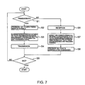
- FIG. 7 is a flow chart showing an operation of the wireless communication apparatus according to the embodiment of this invention.
- FIG. 8 is a block diagram showing a structure of a transmitter according to a first example of this invention.
- FIG. 9 is a block diagram showing a structure of a receiver according to the first example of this invention.
- FIG. 10 is a view for describing resource assignment in the first example of this invention.
- FIG. 11 is a block diagram showing a structure of a transmitting portion of a wireless communication apparatus according to a second example of this invention.
- FIG. 12 is a block diagram showing a structure of a receiving portion of the wireless communication apparatus according to the second example of this invention.
- FIG. 13 is a block diagram showing a structure of a transmitting portion of a wireless communication apparatus according to a third example of this invention.
- FIGS. 14A to 14C are views for describing resource assignment in the third example of this invention.
- FIGS. 15A and 15B are views for describing resource assignment in a fourth example of this invention.
- FIG. 16 is a flow chart showing an operation of a wireless communication apparatus according to a fifth example of this invention.
- FIGS. 17A and 17B are views for describing resource assignment in the fifth example of this invention.
- FIG. 18 is a flow chart showing an operation of the wireless communication apparatus according to the fifth example of this invention.
- FIG. 6 is a block diagram showing a structure of a wireless communication apparatus according to the embodiment of this invention.
- the wireless communication apparatus A includes a transmitting portion B comprising transmitters 1 - 1 to 1 -K, a receiving portion C comprising a receiver 3 , and a recording medium D storing a program (program executable by a computer) to be executed by the transmitting portion B and the receiving portion C and adapted to realize processes at these portions.
- a program program executable by a computer
- FIG. 7 is a flow chart showing an operation of the wireless communication apparatus A in FIG. 6 .
- the process illustrated in FIG. 7 can be realized by making the transmitting portion B and the receiving portion C in the wireless communication apparatus A execute the program of the recording medium D.
- each of the transmitters 1 - 1 to 1 -K produces first through M-th transmission signals (step S 2 in FIG. 7 ), determines correspondence between first through K-th transmission sequences and frequency channels (step S 3 in FIG. 7 ) so that the correspondence is different for each transmission signal, and transmits the transmission signals (step S 4 in FIG. 7 ).
- the wireless communication apparatus A receives a signal sent thereto (step S 6 in FIG. 7 ), extracts and combines M demodulated signals corresponding to each of the first through the K-th transmission sequences in accordance with the correspondence between the first through the K-th transmission sequences and the frequency channels (step S 7 in FIG. 7 ), and produces first through K-th demodulated sequences with reference to the result thereof (step S 8 in FIG. 7 ).
- step S 5 in FIG. 7 the wireless communication apparatus A repeatedly carries out the above-mentioned process.
- the embodiment of this invention is capable of improving characteristics when correlation between propagation paths is high and of realizing high throughput when correlation between propagation paths is low.
- FIG. 8 is a block diagram showing a structure of a transmitter according to a first example of this invention
- FIG. 9 is a block diagram showing a structure of a receiver according to the first example of this invention.
- a wireless communication apparatus according to the first example of this invention is similar in structure to the above-mentioned wireless communication apparatus according to the embodiment of this invention illustrated in FIG. 6 .
- a transmitter 1 - 1 comprises an encoder 11 , an interleaver 12 , a serial/parallel converter 13 , symbol mapping portions 14 and 15 , hopping pattern generating portions 16 and 17 , subcarrier assigning portions 18 and 19 , high-speed inverse Fourier transformers 20 and 21 , guard interval adding portions 22 and 23 , and antennas 24 and 25 .
- Transmitters 1 - 2 to 1 -K are similar in structure to the above-mentioned transmitter 1 - 1 .
- the encoder 11 encodes a transmission sequence S TS1 and produces a coded sequence S CS .
- the interleaver 12 interleaves the coded sequence S CS and produces an interleaved sequence S IS .
- the serial/parallel converter 13 carries out serial/parallel conversion upon the interleaved sequence S IS and produces serial/parallel signals S SP1 and S SP2 .
- the symbol mapping portions 14 and 15 map the serial/parallel signals S SP1 and S SP2 into modulated symbols and produce transmission symbol sequences S TSY and S TSY2 , respectively.
- the hopping pattern generating portions 16 and 17 produce hopping patterns S HP11 and S HP12 independent from each other and unique to the transmitter.
- the subcarrier assigning portions 18 and 19 assign the transmission symbol sequences S TSY1 and S TSY2 to subcarriers 1 to R and produce frequency hopping signals S FH11 to S FH1R and S FH21 to S FH2R , respectively.
- the high-speed inverse Fourier transformers 20 and 21 carry out high-speed inverse Fourier transform upon the frequency hopping signals S FH11 to S FH1R and S FH21 to S FH2R and produce IFFT signals S IFFT1 and S IFFT2 .
- the guard interval adding portions 22 and 23 add guard intervals to the IFFT signals S IFFT1 and S IFFT2 and deliver transmission signals S TSX11 and S TSX12 through the antennas 24 and 25 .
- the transmitters 1 - 2 to 1 -K are operated in the manner similar to the above-mentioned transmitter 1 - 1 and, in response to transmission sequences S TS2 to S TSK , produce transmission signals S TSX21 , S TSX22 , . . . , S TSXK1 , S TSXK2 , respectively.
- a receiver 3 comprises antennas 31 and 32 , guard interval removing portions 33 and 34 , high-speed Fourier transformers 35 and 36 , a MIMO (Multiple-Input Multiple-Output) demodulating portion 37 , hopping pattern generating portions 38 and 39 , subcarrier extracting portions 40 and 41 , parallel/serial converters 42 - 1 to 42 -K, deinterleavers 43 - 1 to 43 -K, and decoders 44 - 1 to 44 -K.
- MIMO Multiple-Input Multiple-Output
- the guard interval removing portions 33 and 34 remove the guard intervals from reception signals S RX1 and S RX2 supplied to the antennas 31 and 32 and produce FFT input signals S FFTI1 and S FFTI2 , respectively.
- the high-speed Fourier transformers 35 and 36 perform high-speed Fourier transform upon the FFT input signals S FFTI1 and S FFTI2 and produce FFT signals S FFT11 to S FFT1R and S FFT21 to S FFT2R , respectively.
- the MIMO demodulating portion 37 combines and decomposes the FFT signals S FFT11 to S FFT1R and S FFT21 to S FFT2R and produces demodulated signals S DEM11 to S DEM1R and S DEM21 to S DEM2R .
- the hopping pattern generating portions 38 and 39 produce unique hopping patterns S HP11 to S HPK1 and S HP12 to S HPK2 corresponding to the transmitters 1 - 1 to 1 -K, respectively.
- the subcarrier extracting portions 40 and 41 extract, from the demodulated signals S DEM11 to S DEM1R and S DEM21 to S DEM2R , components corresponding to the hopping patterns S HP11 to S HPK1 and S HP12 to S HPK2 , and outputs the components as partial demodulated sequences S PDM11 to S PDM1K and S PDM21 to S PDM2K , respectively.
- the parallel/serial converters 42 - 1 to 42 -K carry out parallel/serial conversion upon the partial demodulated sequences S PDM11 to S PDM1K and S PDM21 to S PDM2K and produce demodulated sequences S DMS1 to S DMSK .
- the deinterleavers 43 - 1 to 43 -K deinterleave the demodulated sequences S DMS1 to S DMSK and produce deinterleaved sequences S DIS1 to S DISK , respectively.
- the decoders 44 - 1 to 44 -K decode the deinterleaved sequences S DIS1 to S DMSK and produce decoded sequences S DCS1 to S DCSK , respectively.
- FIG. 10 is a view for describing resource assignment in the first example of this invention. Referring to FIG. 10 , description will be made of the resource assignment in the first example of this invention.
- transmission and reception using a different frequency hopping pattern for each of the transmission antennas of the transmitters 1 - 1 to 1 -K are carried out by the above-mentioned operation.
- MIMO demodulation is carried out after extracting the subcarriers by the hopping patterns, as illustrated in FIG. 5 .
- the hopping pattern is different for each of the transmission antennas of the transmitters 1 - 1 to 1 -K. Therefore, it is necessary to extract the subcarriers by the respective hopping patterns after MIMO demodulation and subsequent decomposition into the demodulated signals corresponding to the respective transmission antennas.
- Each user uses different frequency channels for the transmission antennas # 1 and # 2 . Even if correlation between propagation paths is large, propagation path characteristics are independent in wide-band communication. Therefore, a frequency diversity effect is achieved.
- the same transmission sequence is assigned with a different frequency channel for each transmission antenna. Therefore, even if correlation between propagation paths is high, the diversity effect is obtained.
- FIG. 11 is a block diagram showing a structure of a transmitting portion of a wireless communication apparatus according to a second example of this invention
- FIG. 12 is a block diagram showing a structure of a receiving portion of the wireless communication apparatus according to the second example of this invention.
- the wireless apparatus comprising a plurality of transmitters 1 - 1 to 1 -K and one receiver 3 .
- this invention is readily applicable to a wireless apparatus comprising one transmitter 2 and a plurality of receivers 4 - 1 to 4 -K as illustrated in FIGS. 11 and 12 .
- the transmitting portion of the wireless communication apparatus comprises the transmitter 2 .
- the transmitter 2 comprises encoders 11 - 1 to 11 -K, interleavers 12 - 1 to 12 -K, serial/parallel converters 13 - 1 to 13 -K, symbol mapping portions 14 - 1 to 14 -K and 15 - 1 to 15 -K, hopping pattern generating portions 16 and 17 , subcarrier assigning portions 18 and 19 , high-speed inverse Fourier transformers 20 and 21 , guard interval adding portions 22 and 23 , and antennas 24 and 25 .
- the encoders 11 - 1 to 11 -K encode transmission sequences S TS1 to S TSK and produce coded sequences S CS1 to S CSK .
- the interleavers 12 - 1 to 12 -K interleave the coded sequences S CS1 to S CSK and produce interleaved sequences S IS1 to S ISK .
- the serial/parallel converters 13 - 1 to 13 -K carry out serial/parallel conversion upon the interleaved sequences S IS1 to S ISK and produce serial/parallel signals S SP11 to S SPK1 and S SP21 to S SPK2 .
- the symbol mapping portions 14 - 1 to 14 -K and 15 - 1 to 15 -K map the serial/parallel signals S SP11 to S SPK1 and S SP21 to S SPK2 into modulated symbols and produce transmission symbol sequences S TSY11 to S TSYK1 and S TSY21 to S TSYK2 , respectively.
- the hopping pattern generating portions 16 and 17 produce hopping patterns S HP11 to S HPK1 and S HP12 to S HPK2 independent from each other and unique to the transmitter.
- the subcarrier assigning portions 18 and 19 assign the transmission symbol sequences S TSY1 to S TSYK1 and S TSY21 to S TSYK2 to subcarriers 1 to R and produce frequency hopping signals S FH11 to S FH1R and S FH21 to S FH2R , respectively.
- the high-speed inverse Fourier transformers 20 and 21 carry out high-speed inverse Fourier transform upon the frequency hopping signals S FH11 to S FH1R and S FH21 to S FH2R and produce IFFT signals S IFFT1 and S IFFT2 .
- the guard interval adding portions 22 and 23 add guard intervals to the IFFT signals S IFFT1 and S IFFT2 and deliver transmission signals S TSX11 and S TSX12 through the antennas 24 and 25 .
- the receiving portion of the wireless communication apparatus comprises receivers 4 - 1 to 4 -K.
- the receiver 4 - 1 comprises antennas 31 and 32 , guard interval removing portions 33 and 34 , high-speed Fourier transformers 35 and 36 , a MIMO (Multiple-Input Multiple-Output) demodulating portion 37 , hopping pattern generating portions 38 and 39 , subcarrier extracting portions 40 and 41 , a parallel/serial converter 42 , a deinterleaver 43 , and a decoder 44 .
- the receivers 4 - 2 to 4 -K are similar in structure to the above-mentioned receiver 4 - 1 .
- the guard interval removing portions 33 and 34 remove the guard intervals from reception signals S RX1 and S RX2 supplied to the antennas 31 and 32 and produce FFT input signals S FFTI1 and S FFTI2 , respectively.
- the high-speed Fourier transformers 35 and 36 perform high-speed Fourier transform upon the FFT input signals S FFTI1 and S FFTI2 and produce FFT signals S FFT11 to S FFT1R and S FFT21 to S FFT2R , respectively.
- the MIMO demodulating portion 37 combines and decomposes the FFT signals S FFT11 to S FFT1R and S FFT21 to S FFT2R and produces demodulated signals S DEM11 to S DEM1R and S DEM21 to S DEM2R .
- the hopping pattern generating portions 38 and 39 produce unique hopping patterns S HP11 and S HP12 corresponding to the transmitter 2 , respectively.
- the subcarrier extracting portions 40 and 41 extract, from the demodulated signals S DEM11 to S DEM1R and S DEM21 to S DEM2R , components corresponding to the hopping patterns S HP11 and S HP12 , and output the components as partial demodulated sequences S PDM11 and S PDM21 , respectively.
- the parallel/serial converter 42 carries out parallel/serial conversion upon the partial demodulated sequences S PDM11 and S PDM21 and produces a demodulated sequence S DMS .
- the deinterleaver 43 deinterleaves the demodulated sequence S DMS and produces a deinterleaved sequence S DIS .
- the decoder 44 decodes the deinterleaved sequence S DIS and produces a decoded sequence S DCS1 .
- the same transmission sequence is assigned with a different frequency channel for each transmission antenna. Therefore, even if correlation between propagation paths is high, the diversity effect is obtained.
- FIG. 13 is a block diagram showing a structure of a transmitting portion of a wireless communication apparatus according to a third example of this invention.
- the third example of this invention is similar in structure to the transmitters 1 - 1 to 1 -K and the receiver 3 according to the first example of this invention illustrated in FIGS. 8 and 9 except that the transmitting portion has different structure.
- a receiver of the wireless communication apparatus according to the third example of this invention is similar in structure to the receiver 3 according to the first example of this invention illustrated in FIG. 9 and therefore, description thereof is omitted.
- a transmitter 5 is similar in structure to the transmitter 1 - 1 illustrated in FIG. 8 except that a scheduler 51 is added. Similar parts are designated by like reference numerals. The similar parts are similar to those of the first example of this invention.
- the scheduler 51 determines resource assignment with reference to a reception quality measured at the receiver 3 and produces a resource assignment signal S LA .
- An encoder 11 encodes a transmission sequence S TS1 having a length corresponding to the resource assignment signal S LA and produces a coded sequence S CS .
- An interleaver 12 interleaves the coded sequence S CS having a length corresponding to the resource assignment signal S LA and produces an interleaved sequence S IS .
- a serial/parallel converter 13 carries out serial/parallel conversion upon the interleaved sequence S IS and produces serial/parallel signals S SP1 and S SP2 .
- Symbol mapping portions 14 and 15 map the serial/parallel signals S SP1 and S SP2 into modulated symbols and produce transmission symbol sequences S TSY and S TSY2 , respectively.
- Hopping pattern generating portions 16 and 17 produce hopping patterns S HP11 and S HP12 independent from each other and unique to the transmitter.
- subcarrier assigning portions 18 and 19 assign the transmission symbol sequences S TSY1 and S TSY2 to subcarriers 1 to R and produce frequency hopping signals S FH11 to S FH1R and S FH21 to S FH2R , respectively.
- High-speed inverse Fourier transformers 20 and 21 carry out high-speed inverse Fourier transform upon the frequency hopping signals S FH11 to S FH1R and S FH21 to S FH2R and produce IFFT signals S IFFT1 and S IFFT2 .
- Guard interval adding portions 22 and 23 add guard intervals to the IFFT signals S IFFT1 and S IFFT2 and produce transmission signals S TSX11 and S TSX12 .
- FIGS. 14A to 14C are views for describing resource assignment in the third example of this invention.
- FIG. 14A shows the case of four users.
- FIG. 14B shows the case of three users.
- FIG. 14C shows the case of two users.
- the scheduler 51 adaptively controls the number of transmission sequences depending upon a reception quality at the receiver. For example, consideration will be made about the case where transmission sequences correspond to different users, respectively, and the number of the transmission sequences is equal to four and the number of the frequency channels is equal to 4. Users # 1 to # 4 perform frequency hopping using hopping patterns ⁇ # 1 , . . . ⁇ , ⁇ # 2 , . . . ⁇ , ⁇ # 3 , . . . ⁇ , ⁇ # 4 , . . . ⁇ for the transmission antenna 24 and using hopping patterns ⁇ # 3 , . . . ⁇ , ⁇ # 1 , . . . ⁇ , ⁇ # 4 , . . . ⁇ , ⁇ # 2 , . . . ⁇ for the transmission antenna 25 .
- frequency channel assignment at a time instant # 1 is as shown in FIG. 14A .
- the number of transmission sequences is adaptively controlled depending upon the reception quality. Therefore, it is possible to improve the characteristics when correlation between propagation paths is high and to realize high throughput when correlation between propagation paths is low.
- FIGS. 15A and 15B are views for describing resource assignment in a fourth example of this invention.
- FIG. 15A shows the case of two channels/user/antenna and
- FIG. 15B shows the case of channel assignment reduction.
- a wireless communication apparatus has the above-mentioned structure illustrated in FIG. 13 and the scheduler 51 adaptively controls the number of frequency channels assigned to the transmission sequences depending upon a reception quality at a receiver.
- transmission sequences correspond to different users, respectively, and the number of the transmission sequences is equal to four and the number of the frequency channels is equal to eight for each transmission antenna.
- two frequency channels are assigned to each user for each transmission antenna as shown in FIG. 15A .
- reception quality does not satisfy a required level, frequency channel assignment to each of the users # 3 and # 4 is reduced to one channel for each transmission antenna. Then, with respect to all users, one channel may be prevented from interference from the other transmission antenna as illustrated in FIG. 15B . Thus, characteristics are improved. On the contrary, if the reception quality is excessively higher than the required level, the number of frequency channels is increased. Thus, high throughput is realized.
- FIG. 16 is a flow chart showing an operation of the wireless communication apparatus according to the fourth example of this invention. Referring to FIG. 16 , description will be made of the operation of the wireless communication apparatus according to the fourth example of this invention. A process illustrated in FIG. 16 can be realized by making the transmitting and the receiving portions B and C in the wireless communication apparatus A according to the embodiment of this invention execute the program of the recording medium D.
- step S 11 in FIG. 16 it is assumed that the wireless communication apparatus performs transmission.
- the reception quality at the receiving portion is lower than a predetermined first threshold (reception quality ⁇ first threshold) (step S 12 in FIG. 16 )
- the number of frequency channels to be assigned to the transmission sequence is reduced (step S 13 in FIG. 16 ).
- the reception quality at the receiving portion is higher than a predetermined second threshold (reception quality>second threshold) (step S 14 in FIG. 16 )
- the number of frequency channels to be assigned to the transmission sequence is increased (step S 15 in FIG. 16 ).
- each transmitter produces first through M-th transmission signals (step S 16 in FIG. 16 ), determines correspondence between first through K-th transmission sequences and frequency channels so that the correspondence is different for each transmission signal (step S 17 in FIG. 16 ), and transmits the transmission signals (step S 18 in FIG. 16 ).
- the wireless communication apparatus receives a signal sent thereto (step S 20 in FIG. 16 ).
- M demodulated signals corresponding to the first through the K-th transmission sequences are extracted and combined (step S 21 in FIG. 16 ).
- first through K-th demodulated sequences are produced (step S 22 in FIG. 16 ).
- step S 19 in FIG. 16 the wireless communication apparatus repeatedly carries out the above-mentioned process.
- FIGS. 17A and 17B are views for describing resource assignment in a fifth example of this invention.
- FIG. 17A shows the case of four users.
- FIG. 17B shows the case of reducing the number of transmission antennas to be assigned.
- a wireless communication apparatus has the above-mentioned structure illustrated in FIG. 13 and the scheduler 51 adaptively controls the number of transmission antennas assigned to transmission sequences depending upon the reception quality at the receiver.
- transmission sequences correspond to different users, respectively, and the number of the transmission sequences is equal to four and the number of the frequency channels is equal to four for each transmission antenna.
- the reception quality does not satisfy a required level, the number of transmission antennas assigned to each of the users # 3 and # 4 is reduced to one. Then, with respect to the users # 1 and # 2 , one of the two channels may be prevented from interference from the other transmission antenna, as illustrated in FIG. 17B . Therefore, characteristics are improved.
- the reception quality is excessively higher than the required level, the number of transmission antennas to be assigned is increased so that high throughput is realized.
- FIG. 18 is a flow chart showing an operation of the wireless communication apparatus according to the fifth example of this invention. Referring to FIG. 18 , description will be made about the operation of the wireless communication apparatus according to the fifth example of this invention.
- a process illustrated in FIG. 18 can be realized by making the transmitting and the receiving portions B and C in the wireless communication apparatus A according to the embodiment of this invention execute the program of the recording medium D.
- step S 31 in FIG. 18 it is assumed that the wireless communication apparatus performs transmission.
- the reception quality at the receiving portion is lower than a predetermined first threshold (reception quality ⁇ first threshold) (step S 32 in FIG. 18 )
- the number of transmission antennas to be assigned to the transmission sequence is reduced (step S 33 in FIG. 18 ).
- the reception quality at the receiving portion is higher than a predetermined second threshold (reception quality>second threshold) (step S 34 in FIG. 18 )
- the number of transmission antennas assigned to the transmission sequence is increased (step S 35 in FIG. 18 ).
- each transmitter produces first through M-th transmission signals (step S 36 in FIG. 18 ), determines correspondence between first through K-th transmission sequences and frequency channels so that the correspondence is different for each transmission signal (step S 37 in FIG. 18 ), and transmits the transmission signals (step S 38 in FIG. 18 ).
- step S 31 in FIG. 18 the wireless communication apparatus receives a signal sent thereto (step S 40 in FIG. 18 ).
- M demodulated signals corresponding to each of the first through the K-th transmission sequences are extracted and combined (step S 41 in FIG. 18 ).
- step S 42 in FIG. 18 first through K-th demodulated sequences are produced (step S 42 in FIG. 18 ).
- step S 39 in FIG. 18 the wireless communication apparatus repeatedly carries out the above-mentioned process.
Abstract
Description
Claims (21)
Applications Claiming Priority (3)
| Application Number | Priority Date | Filing Date | Title |
|---|---|---|---|
| JP2003426045 | 2003-12-24 | ||
| JP2003-426045 | 2003-12-24 | ||
| PCT/JP2004/019754 WO2005062510A1 (en) | 2003-12-24 | 2004-12-24 | Wireless communication system, wireless communication apparatus, and resource assignment method used therein |
Publications (2)
| Publication Number | Publication Date |
|---|---|
| US20070160160A1 US20070160160A1 (en) | 2007-07-12 |
| US8027400B2 true US8027400B2 (en) | 2011-09-27 |
Family
ID=34708841
Family Applications (1)
| Application Number | Title | Priority Date | Filing Date |
|---|---|---|---|
| US10/584,738 Expired - Fee Related US8027400B2 (en) | 2003-12-24 | 2004-12-24 | Wireless communication system, wireless communication apparatus, and resource assignment method used therein |
Country Status (5)
| Country | Link |
|---|---|
| US (1) | US8027400B2 (en) |
| JP (1) | JP4780298B2 (en) |
| KR (1) | KR100798664B1 (en) |
| CN (1) | CN1898888B (en) |
| WO (1) | WO2005062510A1 (en) |
Families Citing this family (15)
| Publication number | Priority date | Publication date | Assignee | Title |
|---|---|---|---|---|
| JP4566922B2 (en) * | 2006-02-10 | 2010-10-20 | 日本電信電話株式会社 | Wireless communication method |
| JP4430052B2 (en) * | 2006-06-19 | 2010-03-10 | 株式会社エヌ・ティ・ティ・ドコモ | Mobile communication system, user apparatus and transmission method |
| CN100576836C (en) * | 2006-09-15 | 2009-12-30 | 上海贝尔阿尔卡特股份有限公司 | In the multiple-input, multiple-output wireless network signal is carried out method of subcarrier mapping and device |
| GB2445000B (en) | 2006-12-20 | 2009-04-15 | Toshiba Res Europ Ltd | Wireless communications apparatus |
| US8018983B2 (en) * | 2007-01-09 | 2011-09-13 | Sky Cross, Inc. | Tunable diversity antenna for use with frequency hopping communications protocol |
| CN101400065B (en) * | 2007-09-29 | 2012-11-28 | 中兴通讯股份有限公司 | Signaling representing method for frequency-hopping resource |
| KR101033149B1 (en) * | 2008-04-07 | 2011-05-11 | 캐논 가부시끼가이샤 | Communication system, communication apparatus, and data transmission method |
| KR101216159B1 (en) | 2008-06-20 | 2012-12-27 | 닛본 덴끼 가부시끼가이샤 | Resource allocation method, identification method, base station, mobile station, and recording medium |
| EP4247091A3 (en) | 2008-06-20 | 2023-11-22 | NEC Corporation | Resource allocation method and apparatus |
| US8811371B2 (en) | 2008-09-23 | 2014-08-19 | Qualcomm Incorporated | Transmit diversity scheme for uplink data transmissions |
| KR101040987B1 (en) * | 2008-11-11 | 2011-06-16 | 국방과학연구소 | Apparatus for indentifying hopping data with same signal source and method thereof |
| CN102246446B (en) * | 2008-11-14 | 2014-10-29 | Lg电子株式会社 | Method and apparatus for signal transmission in wireless communication system |
| EP4199446A1 (en) * | 2009-08-25 | 2023-06-21 | Electronics and Telecommunications Research Institute | Method and apparatus for generating/transmitting a frame for wireless communication, and synchronization estimation method for wireless communication |
| CN102082592A (en) * | 2010-12-15 | 2011-06-01 | 北京理工大学 | Communication method of fast frequency hopping multi-transmitting and multi-receiving system based on high-speed bus and GPU (Graphic Processing Unit) |
| CN110808822B (en) * | 2019-10-09 | 2021-05-04 | 西北大学 | Digital random multi-frequency-point frequency hopping time hopping information transmission method and system |
Citations (16)
| Publication number | Priority date | Publication date | Assignee | Title |
|---|---|---|---|---|
| US5548582A (en) | 1993-12-22 | 1996-08-20 | U.S. Philips Corporation | Multicarrier frequency hopping communications system |
| JPH11346203A (en) | 1998-06-02 | 1999-12-14 | Matsushita Electric Ind Co Ltd | Ofdma signal transmitter and its method |
| JP2000092009A (en) | 1998-07-13 | 2000-03-31 | Sony Corp | Communication method, transmitter and receiver |
| JP2002191073A (en) | 2000-12-20 | 2002-07-05 | Canon Inc | Wireless communication system, and communication method in the wireless communication system |
| WO2002061969A1 (en) | 2001-01-30 | 2002-08-08 | Koninklijke Philips Electronics N.V. | Radio communication system |
| WO2002093779A2 (en) | 2001-05-17 | 2002-11-21 | Qualcomm Incorporated | Transmission in multi-channel communication system using selective channel power control |
| JP2003032226A (en) | 2001-07-17 | 2003-01-31 | Matsushita Electric Ind Co Ltd | Radio communication apparatus and method therefor |
| US20030081563A1 (en) * | 2000-02-22 | 2003-05-01 | Ari Hottinen | Method and radio system for digital signal transmission |
| US6563881B1 (en) | 1998-07-13 | 2003-05-13 | Sony Corporation | Communication method and transmitter with transmission symbols arranged at intervals on a frequency axis |
| US6611676B2 (en) * | 1998-04-17 | 2003-08-26 | Matsushita Electric Industrial Co., Ltd. | Radio communication apparatus and transmission rate control method |
| JP2003249914A (en) | 2002-02-26 | 2003-09-05 | Kddi Corp | Adaptive encoding method using spatiotemporal block coding and transmitter |
| JP2003249882A (en) | 2002-02-25 | 2003-09-05 | Ntt Docomo Inc | Channel-assigning method in multi-input/multi-output communication system, program therefor, storage medium and multi-input/multi-output receiver |
| US6728293B1 (en) * | 1999-09-14 | 2004-04-27 | Andrzej Partyka | Hopping pattern generation method in frequency hopping system for intermittent transmission |
| US6760596B1 (en) * | 1999-12-03 | 2004-07-06 | Telefonaktiebolaget Lm Ericsson (Publ) | Method and system for bit-rate adaptation to improve coverage |
| US7031402B2 (en) * | 2001-06-12 | 2006-04-18 | Hitachi Kokusai Electric Inc. | Interference signal removal system |
| US20060215603A1 (en) * | 2003-04-04 | 2006-09-28 | Matsushita Electric Industrial Co., Ltd. | Base station device and communication method |
Family Cites Families (2)
| Publication number | Priority date | Publication date | Assignee | Title |
|---|---|---|---|---|
| US6473467B1 (en) * | 2000-03-22 | 2002-10-29 | Qualcomm Incorporated | Method and apparatus for measuring reporting channel state information in a high efficiency, high performance communications system |
| JP3905118B1 (en) * | 2006-06-21 | 2007-04-18 | 英生 住野 | helmet |
-
2004
- 2004-12-24 US US10/584,738 patent/US8027400B2/en not_active Expired - Fee Related
- 2004-12-24 WO PCT/JP2004/019754 patent/WO2005062510A1/en active Application Filing
- 2004-12-24 JP JP2005516539A patent/JP4780298B2/en not_active Expired - Fee Related
- 2004-12-24 CN CN200480038354XA patent/CN1898888B/en not_active Expired - Fee Related
- 2004-12-24 KR KR1020067014923A patent/KR100798664B1/en not_active IP Right Cessation
Patent Citations (17)
| Publication number | Priority date | Publication date | Assignee | Title |
|---|---|---|---|---|
| US5548582A (en) | 1993-12-22 | 1996-08-20 | U.S. Philips Corporation | Multicarrier frequency hopping communications system |
| US6611676B2 (en) * | 1998-04-17 | 2003-08-26 | Matsushita Electric Industrial Co., Ltd. | Radio communication apparatus and transmission rate control method |
| JPH11346203A (en) | 1998-06-02 | 1999-12-14 | Matsushita Electric Ind Co Ltd | Ofdma signal transmitter and its method |
| US6726297B1 (en) | 1998-06-02 | 2004-04-27 | Matsushita Electric Industrial Co., Ltd. | OFDMA signal transmission apparatus and method |
| US6563881B1 (en) | 1998-07-13 | 2003-05-13 | Sony Corporation | Communication method and transmitter with transmission symbols arranged at intervals on a frequency axis |
| JP2000092009A (en) | 1998-07-13 | 2000-03-31 | Sony Corp | Communication method, transmitter and receiver |
| US6728293B1 (en) * | 1999-09-14 | 2004-04-27 | Andrzej Partyka | Hopping pattern generation method in frequency hopping system for intermittent transmission |
| US6760596B1 (en) * | 1999-12-03 | 2004-07-06 | Telefonaktiebolaget Lm Ericsson (Publ) | Method and system for bit-rate adaptation to improve coverage |
| US20030081563A1 (en) * | 2000-02-22 | 2003-05-01 | Ari Hottinen | Method and radio system for digital signal transmission |
| JP2002191073A (en) | 2000-12-20 | 2002-07-05 | Canon Inc | Wireless communication system, and communication method in the wireless communication system |
| WO2002061969A1 (en) | 2001-01-30 | 2002-08-08 | Koninklijke Philips Electronics N.V. | Radio communication system |
| WO2002093779A2 (en) | 2001-05-17 | 2002-11-21 | Qualcomm Incorporated | Transmission in multi-channel communication system using selective channel power control |
| US7031402B2 (en) * | 2001-06-12 | 2006-04-18 | Hitachi Kokusai Electric Inc. | Interference signal removal system |
| JP2003032226A (en) | 2001-07-17 | 2003-01-31 | Matsushita Electric Ind Co Ltd | Radio communication apparatus and method therefor |
| JP2003249882A (en) | 2002-02-25 | 2003-09-05 | Ntt Docomo Inc | Channel-assigning method in multi-input/multi-output communication system, program therefor, storage medium and multi-input/multi-output receiver |
| JP2003249914A (en) | 2002-02-26 | 2003-09-05 | Kddi Corp | Adaptive encoding method using spatiotemporal block coding and transmitter |
| US20060215603A1 (en) * | 2003-04-04 | 2006-09-28 | Matsushita Electric Industrial Co., Ltd. | Base station device and communication method |
Non-Patent Citations (6)
| Title |
|---|
| Japanese Office Action dated Aug. 4, 2010 with English translation. |
| Japanese Office Action dated Feb. 9, 2011 with English translation. |
| Japanese Office Action dated Oct. 27, 2010 with partial English translation. |
| Ohkawa, Mitsugu, et al. "Improvement of Characteristics for Orthogonal Multicarrier FH-CDMA schemes used Error Correction," The Institute of Electronics, Information and Communication Engineers, vol. 94, No. 546, Fig. 2, Mar. 16, 1995. |
| Takuya Kadoya et al., "Studies on MMFSK System, Construction of hopping pattern, Parallel MMFSK System" Technical Report of IEICE, SST, Spread Spectrum, Japan, The Institute of Electronics, Information and Communications Engineers; Oct. 13, 2000; vol. 100, No. 362, pp. 25-30. |
| Van Nee, Richard, et al. "Maximum Likelihood Decoding in a Space Division Multiplexing System," IEEE VTC 2000 Spring Proceedings, May 2000, pp. 6-10. |
Also Published As
| Publication number | Publication date |
|---|---|
| CN1898888B (en) | 2011-01-12 |
| KR100798664B1 (en) | 2008-01-28 |
| WO2005062510A1 (en) | 2005-07-07 |
| CN1898888A (en) | 2007-01-17 |
| JP4780298B2 (en) | 2011-09-28 |
| JPWO2005062510A1 (en) | 2007-07-19 |
| KR20070005571A (en) | 2007-01-10 |
| US20070160160A1 (en) | 2007-07-12 |
Similar Documents
| Publication | Publication Date | Title |
|---|---|---|
| US8027400B2 (en) | Wireless communication system, wireless communication apparatus, and resource assignment method used therein | |
| KR101484790B1 (en) | New frame and training pattern structure for multi-carrier systems | |
| US7593472B2 (en) | Methods and apparatus for circulation transmissions for OFDM-based MIMO systems | |
| KR101178818B1 (en) | Repetition coding for a wireless system | |
| KR100909802B1 (en) | Time varying cyclic delay diversity of ofdm | |
| US7729447B2 (en) | Interleaver design with multiple encoders for more than two transmit antennas in high throughput WLAN communication systems | |
| KR101407367B1 (en) | Method and system of interleaving for a multiple-input multiple-output multi-band ofdm communication system | |
| JP5236807B2 (en) | Communication device | |
| US9385907B2 (en) | Dual re-configurable logic devices for MIMO-OFDM communication systems | |
| CA2421768A1 (en) | Cyclic delay diversity for mitigating isi in ofdm systems | |
| US20060056540A1 (en) | Dynamic pilot subcarrier and data subcarrier indexing structure for wireless MIMO communication systems | |
| KR20070045343A (en) | Transmitting apparatus, receiving apparatus, communication system and communication method | |
| JP4300368B2 (en) | Apparatus and method for generating transmission signal from multi-user signal and extracting user signal | |
| KR100769671B1 (en) | MB-OFDM transmitter and receiver and signal processing method thereof | |
| JP4339850B2 (en) | Apparatus and method for providing a transmitted multi-carrier signal, and apparatus and method for providing an output signal from a received multi-carrier signal | |
| Wiegandt et al. | High-throughput, high-performance ofdm via pseudo-orthogonal carrier interferometry type 2 | |
| JP2007515829A (en) | Multi-carrier system with transmit diversity | |
| KR101346423B1 (en) | Method for transmitting data in multiple antenna system | |
| JP7304406B2 (en) | Sending and receiving signals | |
| US20060077944A1 (en) | Backward compatible transmitter diversity scheme for use in an ofdm communication system | |
| JP2003069529A (en) | Device and method for ofdm signal reception and device and method for ofdm signal transmission | |
| Gidlund et al. | Performance and capacity improvements of OFDM wireless LANs with multiple antennas and subchannel power control |
Legal Events
| Date | Code | Title | Description |
|---|---|---|---|
| AS | Assignment |
Owner name: NEC CORPORATION, JAPAN Free format text: ASSIGNMENT OF ASSIGNORS INTEREST;ASSIGNOR:KAKURA, YOSHIKAZU;REEL/FRAME:018032/0986 Effective date: 20060620 |
|
| ZAAA | Notice of allowance and fees due |
Free format text: ORIGINAL CODE: NOA |
|
| ZAAB | Notice of allowance mailed |
Free format text: ORIGINAL CODE: MN/=. |
|
| STCF | Information on status: patent grant |
Free format text: PATENTED CASE |
|
| FPAY | Fee payment |
Year of fee payment: 4 |
|
| MAFP | Maintenance fee payment |
Free format text: PAYMENT OF MAINTENANCE FEE, 8TH YEAR, LARGE ENTITY (ORIGINAL EVENT CODE: M1552); ENTITY STATUS OF PATENT OWNER: LARGE ENTITY Year of fee payment: 8 |
|
| FEPP | Fee payment procedure |
Free format text: MAINTENANCE FEE REMINDER MAILED (ORIGINAL EVENT CODE: REM.); ENTITY STATUS OF PATENT OWNER: LARGE ENTITY |
|
| LAPS | Lapse for failure to pay maintenance fees |
Free format text: PATENT EXPIRED FOR FAILURE TO PAY MAINTENANCE FEES (ORIGINAL EVENT CODE: EXP.); ENTITY STATUS OF PATENT OWNER: LARGE ENTITY |
|
| STCH | Information on status: patent discontinuation |
Free format text: PATENT EXPIRED DUE TO NONPAYMENT OF MAINTENANCE FEES UNDER 37 CFR 1.362 |
|
| FP | Lapsed due to failure to pay maintenance fee |
Effective date: 20230927 |